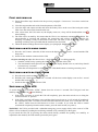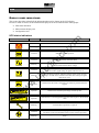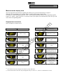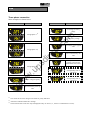
1
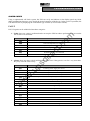
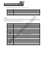
ct re di .u ps w w w .c om INTRODUCTION Thank you for choosing our product. The manufacturers are highly specialized in the development and production of uninterruptible power systems (UPS). The UPSs of this series are high quality products, designed and manufactured to ensure optimum performance. This device can be used by anyone, provided that they READ THIS MANUAL CAREFULLY AND THOROUGHLY BEFOREHAND. .c om This manual contains detailed instructions for the use and installation of the UPS. For information on use and in order to get the most out of this device, this manual should be kept close to the UPS and CONSULTED BEFORE CARRYING OUT ANY OPERATIONS ON IT. ENVIRONMENTAL PROTECTION ct During the development of its products, the company uses extensive resources with regards to all environmental aspects. re All our products pursue the objective defined in the environmental management system developed by the company in compliance with standards in force. di No hazardous materials such as CFC, HCFC or asbestos are used in this product. .u ps When evaluating packaging, the choice of material has been made favouring recyclable materials. For correct disposal, please separate and identify the type of material of which the packaging is made in the table below. Dispose of all material in compliance with standards in force in the country in which the product is used. Material Heat-treated pine Stratocell/cardboard Cardboard Stratocell HD Polyethylene w w w Description Pallet Packaging corner Box Adhesive pad Protective bag DISPOSING OF THE PRODUCT The UPS contains internal material that (in case of dismiss / disposal) are considered TOXIC and HAZARDOUS WASTE, such as electronic circuit boards and batteries. Treat these materials according to the laws applicable referring to qualified service personnel. Their proper disposal contributes to respect the environment and human health. © Reproduction of any part of this manual, including partial, is strictly prohibited without the prior consent of the manufacturer. For the purpose of improving it, the manufacturer reserves the right to modify the product described herein at any time and without notice. CONTENTS PRESENTATION 5 UPS VIEWS DISPLAY MASK VIEW 6 7 INSTALLATION 8 OPENING THE PACKAGING AND CHECKING ITS CONTENTS INSTALLATION PROCEDURES 8 9 USE 10 .c om CONNECTIONS SINGLE-PHASE VERSION THREE-PHASE VERSION Single-phase connection Measurements display area .u ps Single-phase connection di UPS status indicators re Version with external remote By-pass command FIRST SWITCHING-ON SWITCHING-ON WITH MAINS POWER SWITCHING-ON WITH BATTERY POWER SWITCHING OFF THE UPS DISPLAY PANEL INDICATIONS Three-phase connection 12 13 14 15 15 15 15 16 16 17 17 18 19 20 20 20 21 23 w w Configuration area OPERATING MODES R.E.P.O. PROGRAMMABLE AUXILIARY SOCKET (POWER SHARE) UPS CONFIGURATION COMMUNICATION PORTS RS232 and USB connectors ct Three-phase connection 10 11 12 23 Monitoring and control software 24 Configuration software 24 TROUBLESHOOTING 25 w Communication Slot SOFTWARE ALARM CODES TECHNICAL DATA TABLE UPS TECHNICAL DATA TABLE TABLE OF OVERLOAD TIMES 23 24 27 29 29 31 ct re di .u ps w w w .c om PRESENTATION w w w .u ps di re ct .c om The SPW-SPT UPS range has been designed using the state-of-the-art in technology available today, so as to guarantee the user maximum performance levels. The use of multiprocessors combined with high-frequency IGBT technology, grants optimum performance in terms of distortion and efficiency. Thanks to its modern design, use of a wide graphic display and highly versatile setting possibilities, the SPW-SPT range represents a reference in the universe of three-phase/single-phase and single-phase/singlephase UPS’s. Nominal power Nominal voltage Dimensions H x L x D Weight (1) [VA] [Vac] [mm] [Kg] SPW 5000 NP SPW 6000 NP SPT 6500 NP SPT 8000 NP SPT 10000 NP 5000 6000 8000 10000 89 90 6500 220/230/240 [615 x 282 x 785] (1) 91 94 95 The dimensions are for a UPS including back-pack module PRESENTATION UPS VIEWS di re ct .c om Display Main switch .u ps Front view COMUNICATION SLOT (for expansions) Remote emergency power off (R.E.P.O.) Cooling fan IEC 10 A Power share sockets USB communication port w w w Cooling fan RS232 communication port Power share fuse Input and output switches Manual bypass switch Battery fuse Removable back-pack Rear view PRESENTATION DISPLAY MASK VIEW “SEL / SET” button “ON” button w w w .u ps di re ct .c om “STBY” button 1 Normal operation 7 Configuration area 2 Operation from mains 8 Maintenance request 3 Operation from battery 9 Timer 4 Load powered by the bypass 10 Measurement display area 5 Battery back up time indicator 11 Stand-by/alarm 6 Load level indicator INSTALLATION OPENING THE PACKAGING AND CHECKING ITS CONTENTS After opening the pack, make a check of the contents first of all. The pack should contain: RS232 serial cable .u ps di User's manual w w Slide w 2 Battery fuses - 14x51 mm, 50A, 400V re User manual + CD-ROM with software ct .c om UPS Jumper (only into 3phases–1phase versions) INSTALLATION WARNING: this UPS product conforms to the current electromagnetic compatibility (EMC) regulations (C2 class). It may cause radio interference in the home environment. The user may have to adopt supplementary measures. The manufacturers cannot accept liability for damage caused by wrong connections or by operations other than those described in this manual. INSTALLATION PROCEDURES .c om Before connecting the UPS to the Battery box, ensure compliance with the following points: Install the UPS and the Battery box on a flat, stable surface. Avoid placing in positions exposed to direct sunlight or hot air Avoid dusty environments. re The ambient humidity rate must not exceed 90%. ct Maintain room temperature between 0°C and 40°C N.B.: the UPS can operate with an ambient temperature of between 0°C and 40°C. The optimal operating temperature for the batteries inside the UPS is between 20 and 25°C. If the operational lifetime of the batteries is an average of 4 years with an ambient temperature of 20°C, this will be halved if the temperature goes up to 30°C. w w w .u ps di Ensure that the UPS and the Battery box are placed with the front and the rear at least 10 cm away from walls. Do not place objects on top of the ventilation holes in order to allow adequate ventilation. USE CONNECTIONS INSTALLATION MUST ONLY BE PERFORMED BY QUALIFIED PERSONNEL. THE FIRST CONNECTION TO BE MADE IS THAT OF THE PROTECTION CONDUCTOR (EARTH CABLE), TO THE TERMINAL MARKED . THE UPS MUST NEVER BE MADE OPERATE WITHOUT A CONNECTION TO THE EARTHING SYSTEM. ct .c om Warning: providing it complies with the neutral (N) and phase (F) indications for plugs and sockets, the UPS, when inserted in an installation, does not alter the existing neutral arrangements. The resistance on the neutral connection must be less than 0.1 ohm. A differential switch upstream will also be triggered for a fault occurring downstream of the UPS. In calculating reactivity of this switch, account must be taken of the leakage current of the UPS (approx. 2 mA) plus that of the load which come together on the UPS’s earth conductor. The neutral arrangements are altered only if there is also an isolating transformer or when the UPS operates with a neutral that is disconnected upstream. In any case avoid connecting the output neutral with the input neutral or to the earth as this could damage the UPS. re To make the mains power and load connections, follow the instructions below: .u ps di 1. Install a 63A magneto-thermal switch with intervention curve B or C upstream of the machine (4 poles for three-phase versions, 2 poles for single-phase versions). w w w 2. The terminals to be used for connection of the input and output connections are located on the inside of the back-pack. Next unscrew the back-pack fastening screws (two each side) on the sides of and above the back-pack (see figure to the side). 3. Lift the back-pack off (see figure to the side). WARNING: the backpack is connected to the back of the UPS by way of an earth cable which prevents it from being taken away completely. Do not try to separate the back-pack from the UPS. USE SINGLE-PHASE VERSION 1. (SINGLE-PHASE CONNECTION 5-6kVA): use 3 cables with cross-section 6 mm2 (EARTH, N and L) for the input, and 3 cables with cross-section 6 mm2 for the output (EARTH, N and L). di re ct .c om 2. Connect the wires to the relative terminals, following exactly the instructions given below: Input line a - Make sure that the magneto-thermal switch upstream is open. b - Connect the earth wire to terminal B. c - Connect the neutral wire to terminal 4. d - Connect the live wire to terminal 3. Output line a - Connect the earth wire to terminal C. b - Connect the neutral wire to terminal 6. c - Connect the live wire to terminal 5. By-pass line a - Make sure that a jumper is connected between terminals 7 and 8, needed for proper operation of the UPS. A B C 3 4 5 6 7 8 L N L N REMOTE BYPASS w w w .u ps 2 - 1 + BATT. EXP. IN OUT 3. Tighten the terminals well, close the back-pack and secure it with the screws taken out earlier. USE THREE-PHASE VERSION Single-phase connection 1. (SINGLE-PHASE CONNECTION 8-10kVA): use 3 cables of cross-section 10 mm2 (EARTH, N and L) for the input, and 3 cables of cross-section 10 mm2 for the output(EARTH, N and L). (SINGLE-PHASE CONNECTION 6.5kVA): use 3 cables of cross-section 6 mm2 (EARTH, N and L) for the input, and 3 cables of cross-section 6 mm2 for the output(EARTH, N and L). .u ps di re ct .c om 2. Short-circuit the input terminals (3, 4 and 5) with the jumper provided in the accessories kit. Connect the wires to the respective terminals, following exactly the instructions below: Input line a - Ensure that the upstream magneto-thermal switch is open. b - Connect the earth wire to terminal B. c - Connect the neutral wire to terminal 6. d - Connect the live wire to terminal 4. Output line a - Connect the earth wire to terminal C. b - Connect the neutral wire to terminal 8. c - Connect the live wire to terminal 7. By-pass line a - Ensure that a jumper is connected on terminals 9 and 10, this is necessary for correct operation of the UPS. JUMPER 2 3 B 4 5 C 6 7 8 9 10 N L N REMOTE BYPASS w w w A 1 L1 BATT. EXP. IN OUT 3. Tighten the terminals well, close the back-pack and secure it with the screws taken out earlier. 4. Configure the single-phase configuration using the configuration software (see paragraph Configuration software). USE Three-phase connection 1. (THREE-PHASE CONNECTION 8-10kVA): Use 3 cables of cross-section 6 mm2 (EARTH, L2 and L3) and 2 with cross-section 10 mm2 (N, L1) for the input (N.B.: L1 and N are of greater crosssection because in bypass operation they have to carry all of the input current). For the output use 3 cables of cross-section 10 mm2 (EARTH, N and L). (THREE-PHASE CONNECTION 6.5kVA): Use 3 cables of cross-section 4 mm2 (EARTH, L2 and L3) and 2 of cross-section 6 mm2 (N, L1) for the input (N.B.: L1 and N are of greater cross-section because in bypass operation they have to carry all of the input current). For the output use 3 cables of cross-section 6 mm2 (EARTH, N and L). .u ps di re ct .c om 2. Connect the wires to the respective terminals, following exactly the instructions below: Input line a - Ensure that the upstream magneto-thermal switch is open. b - Connect the earth wire to terminal B. c - Connect the neutral wire to terminal 6. d - Connect the wires of the phases to terminals 3, 4 and 5 (for L1 use red wire). Output line a - Connect the earth wire to terminal C. b - Connect the neutral wire to terminal 8. c - Connect the live wire to terminal 7. By-pass line a - Ensure that a jumper is connected on terminals 9 and 10, this is necessary for correct operation of the UPS. B C 3 4 5 6 7 8 9 10 L1 L2 L3 N L N REMOTE BYPASS w w 2 - w A 1 + BATT. EXP. IN OUT 3. Tighten the terminals well, close the back-pack and secure it with the screws taken out earlier. USE Version with external remote By-pass command To be able to control the remote maintenance By-Pass externally, follow points 1, 2 and 3 described above. Then proceed as follows: 11 12 13 .c om 1. Follow the instructions given above for the connection, number and cross-section of the cables to use for the power connections. For the connection with the remote Bypass terminals use a 2x0.75 mm2 cable. ct 2. Connect the wires to the respective terminals following the instructions described above. The By-pass line can be connected either with the UPS in a single-phase connection or a three-phase connection. Connect the wires of the By-pass lines as follows: .u ps di re By-pass line Connect the two cable leads to terminals 12 and 13 to properly control the remote By-pass externally. REMOTE BYPASS w w 3. Tighten the terminals well, close the back-pack and secure it with the screws taken out earlier. w A WARNING LABEL MUST BE PUT ON ALL MAINS POWER DISCONNECTING SWITCHES INSTALLED REMOTE FROM THE AREA OF THE UPS, IN ORDER TO ALERT ALL SERVICE OPERATORS THAT THE CIRCUIT IS CONNECTED TO A UPS. THE LABEL MUST BEAR THE FOLLOWING WORDING: ISOLATE THE UPS BEFORE WORKING ON THIS CIRCUIT USE FIRST SWITCHING-ON 1) Ensure that all the steps described in the previous paragraph “Connections” have been carried out correctly. 2) Close the magneto-thermal switch located upstream of the UPS. 3) Close the input and output switches and insert the battery fuses on the rear of the back-pack on the UPS. Close the main switch located on the rear. .c om 4) After a short time, the UPS comes on, the display comes on, a beep will be heard and the icon starts blinking. 5) The UPS will be in stand-by: this means that the UPS is in a minimum consumption condition. The microcontroller is powered and performs the supervision and self-test tasks; the batteries are charging; everything is ready for activation of the UPS. The UPS is also in Stand-by status when operating on battery power provided that the timer has been activated. 6) Check the default settings shown on the display (see paragraph: Configuration area) SWITCHING-ON WITH MAINS POWER re ct 1) Press the “ON” button. After this, all the icons on the display will come on for 1 second and the UPS beeps once. 2) Switch on the machine connected to the UPS. On first switching-on only: after about 30 sec., check that the UPS is working properly: 1. Simulate a black-out by opening the switch located upstream of the UPS. .u ps di on the display should come on, and a beep should 2. The load should remain powered, the icon be heard every 4 seconds. 3. When the switch upstream is closed again, the UPS should return to working on mains power. SWITCHING-ON WITH BATTERY POWER w 1) Press the main switch on the rear of the UPS. 2) Hold the “ON” button down for at least 5 seconds. All the icons on the display come on for 1 second and the UPS beeps once. 3) Switch on the items connected to the UPS. w SWITCHING OFF THE UPS w To switch the UPS off, hold the “STBY” button down for at least 1.5 seconds. The UPS goes back into stand-by state and the icon starts blinking: a. If the mains is present, to switch the UPS off completely, press the main switch so as to bring the switch back into “0” position . b. If the UPS is working off battery power and the timer has not been set, it will switch off completely and automatically after 5 seconds. If on the other hand the timer has been set, to switch the UPS off, the “STBY” button must be held down for at least 5 seconds. If you want the UPS to remain switched off completely when the mains returns, press the main switch (see point a.). WARNING: the UPS is provided with a redundant emergency power supply which, in the event of a UPS failure, will cut in thereby avoiding the load being switched off by switching it to the bypass. If you switch the UPS off by pressing the main switch directly (without first putting it in stand-by as explained in the manual), the load remains powered by the bypass. USE DISPLAY PANEL INDICATIONS This section describes in detail all the information that can be shown on the LCD display. In order to make it clearer, all the information displayed can be divided into three main groups: UPS status indicators Measurements display area Configuration area UPS status indicators STATUS DESCRIPTION .c om ICON Constant Indicates a fault The UPS is in stand-by state Constant Indicates regular operation The UPS is operating from the mains, but the output voltage is not synchronized with the mains voltage The UPS is operating from the battery. When it is in this state the UPS emits an acoustic signal (beep) at regular intervals of 4 sec. .u ps Constant re Flashing The UPS is operating from the mains di Constant ct Flashing w w w Flashing End of discharge prealarm. Indicates that the battery back up time is coming to an end. In this condition the UPS emits a beep at regular intervals of 1 sec. Constant Indicates that the loads connected to the UPS are powered from the bypass Dynamic Indicates the estimated percentage of back-up time Dynamic Indicates the % of load applied to the UPS with respect to the nominal value Flashing A maintenance operation is required Constant Flashing Indicates that the timer is activated (programmed start-up or shutdown). The timer can be activated/deactivated via the software provided 1 minute to go before the UPS starts up or 3 minutes before it shuts down USE Measurements display area The most important measurements regarding the UPS may be posted on the display in sequence. When the UPS is switched on, the display shows a reading of the mains voltage value. To change to a different display, press the “SEL / SET” button repeatedly until the desired quantity appears. If there is a failure / alarm (FAULT) or a block (LOCK), the display will automatically show the type and code of the corresponding alarm. Single-phase connection GRAPHIC EXAMPLE (1) .c om Some examples are shown below: DESCRIPTION GRAPHIC EXAMPLE re di Mains frequency ct Mains voltage (1) DESCRIPTION Total battery voltage Percentage of the applied load Current absorbed by the load Output voltage frequency Temperature of the cooling system for the UPS internal electronics w .u ps Voltage output from the UPS Percentage of battery charge Lock (2): the corresponding code is displayed w w Residual battery back up time Fault/Alarm (2): the corresponding code is displayed (1) The values shown in the images in the table are purely indicative. (2) The FAULT/LOCK codes can only be displayed if they are active (i.e., if there is a fault/alarm or a lock). USE Three-phase connection Some examples are shown below: GRAPHIC EXAMPLE (1) GRAPHIC EXAMPLE (1) DESCRIPTION DESCRIPTION Percentage of battery charge .c om Voltage phase 1 (2) Total battery voltage ct Percentage of the applied load .u ps di re Voltage phase 2 (2) Current absorbed by the load Temperature of the cooling system for the UPS internal electronics w Voltage phase 3 (2) w w Output voltage frequency Fault/Alarm (3): the corresponding code is displayed Lock (3): the corresponding code is displayed Residual battery back up time (1) The values shown in the images in the table are purely indicative. (2) Alternative indication Phase No./Voltage. (3) The FAULT/LOCK codes can only be displayed if they are active (i.e., if there is a fault/alarm or a lock). USE Configuration area The configuration area groups together the main UPS operating parameters and displays its current status. The parameters contained in this area can be changed directly from the display panel. SETTABLE PARAMETERS: Frequency: Output voltage frequency Voltage: Output voltage Mode: UPS operating mode .c om Frequency Voltage Mode re ct The image at the side shows the display zone for the settings (configuration area) showing the three settable parameters. How to change the settings: di To access the configuration area, hold the “SEL/SET” button down for at least 2 sec. The word “SET” will light up and an arrow ( ► ) will appear to the left of Frequency. .u ps The arrow shows the selected setting. To select a different parameter press the “SEL/SET” button. To change the selected item, press the “ON” button. To exit from the configuration area, hold the “SEL/SET” button down for at least 2 sec. □ Off (frequency auto-sensing) □ 220 V □ 230 V □ 240 V □ ECO □ SMART w Voltage: □ 60 Hz □ 50 Hz w Frequency: w POSSIBLE SETTINGS Mode: □ ON LINE □ STBYOFF NOTE: Changes in the output frequency configuration will only become effective when the UPS has been completely shut down and restarted (via the general switch). THE OUTPUT FREQUENCY AND VOLTAGE PARAMETERS MUST BE COMPATIBLE WITH THE PARAMETERS OF THE LOAD POWERED BY THE UPS USE OPERATING MODES The mode that ensures maximum protection to the load is ON LINE mode (default), where the energy for the load undergoes a double conversion and is reconstructed fully sinusoidal in output with frequency and voltage set by accurate digital microprocessor control independently of the input (V.F.I.). * The following modes can be set in addition to the conventional ON LINE double conversion operating mode: ECO (LINE INTERACTIVE) SMART (SMART ACTIVE) .c om STBYOFF (STAND-BY OFF) The load is normally powered from the bypass in ECO mode, in order to optimize efficiency. If the mains goes out of the admitted tolerances, the UPS switches to normal ON LINE double conversion operation. About five minutes after the mains returns within tolerance, the load is once again switched onto the bypass. ct If the user cannot decide which operating mode is the most suitable (ON LINE or ECO), this decision can be left to SMART ACTIVE mode. In this mode, the UPS decides autonomously which mode to configure on the basis of statistics collected on the quality of the mains power supply. di re STAND-BY OFF mode is used for operation as a back-up unit: when the mains is present, the load is unpowered while if a blackout occurs, the load is powered from the inverter via the batteries. .u ps R.E.P.O. w This isolated input is used to remotely switch off the UPS in an emergency. Any “Remote Emergency Power Off” (R.E.P.O.) switch that is normally closed must be connected to the connector located at the back of the UPS. The UPS is supplied ex-works with the R.E.P.O. terminals short circuited: remove the short circuit if this contact is connected to the auxiliary of a remote emergency switch. w The R.E.P.O. circuit is self-powered with SELV type circuits. No external power supply voltage is therefore required. When it is closed (normal condition) there is a current of 10mA max. w PROGRAMMABLE AUXILIARY SOCKET (POWER SHARE) The UPS is provided with an output socket that allows the automatic disconnection of the load applied to it under certain operating conditions. The events that determine the automatic cut-out of the Power share socket can be user-selected by means of the configuration software (see paragraphs Configuration software and UPS Configuration). It is possible for example to select cut-out after a certain time of operation from battery, or on reaching the end of the battery discharging prealarm threshold, or in the event of an overload. * The rms value of the output voltage is fixed by accurate microprocessor control independently of the input voltage while the frequency of the output voltage is synchronized (within a user-selectable tolerance) with that of the input to enable use of the bypass. The UPS will desynchronize outside of this tolerance, returning to nominal frequency, and the bypass can no longer be used (free running mode). USE UPS CONFIGURATION The following table shows all the possible configurations available to adapt the UPS to the user’s requirements. KEY: Indicates that the configuration can be changed from the display panel as well as by means of the configuration software. = = Output frequency To select the nominal output frequency PREDEFINED POSSIBLE CONFIGURATIONS Auto 50 Hz 60 Hz Auto: automatic sensing from the input frequency ct DESCRIPTION Output voltage To select the nominal output voltage Operating mode To select one of the 4 different operating modes ON LINE Delay before automatic restart after the mains returns 5 sec. .u ps w 220V 230V 240V 220 ÷ 240 in 1V steps (only via software) ON LINE ECO SMART ACTIVE STAND-BY OFF di 230V w Start-up delay re FUNCTION .c om Indicates that the configuration can only be changed via the configuration software. Disabled 1 ÷ 255 in 1 sec. steps Disabled Enabled Disabled Back up time limit Maximum time of operation from the battery Disabled Disabled (full battery discharge) 1 ÷ 65000 in 1 sec. steps End of discharge alert Estimated remaining back up time for the end of discharge alert 3 min. 1 ÷ 255 in 1 min. steps Battery test Time interval for the automatic battery test 40 hours Disabled 1 ÷ 1000 in 1 hour steps w Shutdown due to minimum load Automatic shutdown of the UPS in operation from the battery if the load is less than 5% MODE USE FUNCTION DESCRIPTION PREDEFINED Alarm threshold for maximum load Selects the user overload limit Disabled Display brightness Selects the level of brightness of the LCD display Maximum Minimum ÷ Maximum in 20 steps Acoustic alarm Selects the operating mode of the acoustic alarm Low Normal Low: does not sound for momentary bypass intervention Always connected Always connected Disconnection after n seconds of operation from battery Disconnection after n seconds from the end of discharge prealarm signal ... (see configuration software manual) ct .c om Disabled 0 ÷ 103 in 1% steps re Selects the operating mode of the auxiliary socket Auxiliary socket (power share) POSSIBLE CONFIGURATIONS ADVANCED SETTINGS Selects the allowed voltage range for the passage onto bypass ± 0.25% ± 0.5% ± 0.75% ± 1÷ ±10 in 1% steps di Bypass voltage thresholds ± 5% .u ps Input frequency tolerance Selects the allowed input frequency range for the passage onto bypass and for synchronization of the output Low: 180 ÷ 200 in 1V steps High: 250 ÷ 264 in 1V steps Selects the allowed voltage range for operation in ECO mode Low: 200V High: 253V Low: 180 ÷ 220 in 1V steps High: 240 ÷ 264 in 1V steps Sensitivity of intervention for ECO Selects the sensitivity of intervention during operation in ECO mode Normal Power supply of the load in standby Power supply of the load on bypass with UPS switched off (stand-by state) Disabled (load Disabled (not powered) NOT powered) Enabled (powered) Selects the mode of use of the bypass line Enabled/High sensitivity Enabled/Low sensitivity Enabled / Disabled with input/output High sensitivity synchronization Disabled without input/output synchronization w Low: 180V High: 264V w w Bypass voltage thresholds for ECO Bypass operation Low Normal High MODE USE COMMUNICATION PORTS The following communication ports are located at the back of the UPS (see UPS Views): Serial port, available with RS232 connector and USB connector. NOTE: use of one connector automatically excludes the other. Expansion slots for additional COMMUNICATION SLOT interface cards. RS232 and USB connectors USB CONNECTOR .u ps di SIGNAL Contact closed: UPS locked * TXD RXD GND Interface power supply input +12Vdc Contact closed: end of discharge prealarm * Contact closed: operation from battery * w PIN # 1 2 3 4 5 6 7 8 9 re ct .c om RS232 CONNECTOR w * Optoisolated contact max. +30Vdc/10mA Communication Slot w The UPS is provided with an expansion slot for optional communication cards (see figure at the side) which enable the device to dialog using the main communication standards. Some examples: Second RS232 port Serial duplexer Ethernet network agent with TCP/IP, HTTP and SNMP protocol RS232 port + RS485 with JBUS/MODBUS protocol Signalling relay card Refer to the manufacturer’s website for more information on the accessories that are available. PIN # 1 2 3 4 4 3 1 2 SIGNAL VBUS DD+ GND USE .c om SOFTWARE Monitoring and control software ct The UPSmon software provides effective and intuitive management of the UPS, displaying all the most important information, such as input voltage, load applied, and battery capacity. It is also able to automatically effect operations such as shutdown, transmission of e-mails, SMS and network messages when particular events that can be selected by the user occur. Installation procedure: .u ps di re Connect the UPS’s RS232 communication port to a COM communication port on the PC by means of the serial cable provided* or connect the USB port on the UPS to a USB port on the PC using a USB standard cable*. Download the software from www.ups-technet.com, selecting the desired operating system. Follow the installation program instructions. For more detailed information about installation and use, refer to the software manual which can be downloaded from our website www.ups-technet.com. Configuration software w The UPStools software allows the configuration and full display of the status of the UPS via USB or RS232. For a list of possible configurations available to the user, refer to the UPS Configuration paragraph. w w INSTALLATION OPERATIONS 1) Connect one of the UPS’s communication ports to one of the PC’s communication ports using the cable supplied. 2) Follow the installation instructions shown within the software manual which can be located in the UPSTools directory or downloaded from the web site www.ups-technet.com. CAUTION: If the RS232 communication port is used, it is not possible to communicate with the USB port and vice versa.It is advisable to use a cable which is shorter than 3 metres for communication with the UPS. To obtain additional communication ports with different functions, independent from the standard USB and RS232 ports on the UPS, various accessories are available which can be inserted into the communication card slot. To check the availability of new, more updated software versions and for more information about the accessories available, consult the website www.ups-technet.com. * It is recommended to use a cable with a max. length of 3 metres. TROUBLESHOOTING Irregular functioning of the UPS is most often not an indication of a fault but due simply to trivial problems, minor difficulties or carelessness. We therefore recommend that you refer to the table below which gives a summary of useful information to solve the most common problems. PROBLEM POSSIBLE CAUSE SOLUTION MAIN SWITCH NOT CLOSED Ensure that the main switch located on the rear panel is in position “I”. Check the connection to the mains power. MAINS VOLTAGE DOWN (BLACK-OUT) Check that there is a mains voltage present. ct NO CONNECTION TO THE MAINS LINE Reset the protection. WARNING: Check that there is not an overload on the UPS output. re DISPLAY DOESN’T COME ON .c om BATTERY FUSE-HOLDER Check the battery fuses and close the disconnecting DISCONNECTING SWITCHES switches. ARE OPEN di UPSTREAM PROTECTION TRIGGERED .u ps UPS IS IN STAND-BY STAND-BY OFF MODE HAS BEEN SELECTED The mode has to be changed. In STAND-BY OFF (emergency) mode, the loads are only powered in the event of a black-out. NO CONNECTION TO THE LOAD Check the connection to the load and close the output disconnecting switch. w w DISPLAY IS ON BUT THE LOAD IS NOT POWERED w THE UPS IS OPERATING FROM BATTERY EVEN THOUGH THE MAINS VOLTAGE IS PRESENT THE UPS DOES NOT SWITCH ON AND THE DISPLAY SHOWS ONE OF THESE CODES: A06, A08 THE DISPLAY SHOWS THE CODE: A11 Press the “ON” button on the front panel so as to power the loads. UPSTREAM PROTECTION TRIGGERED Reset the protection. WARNING: Check that there is no overload in output to the UPS. THE INPUT VOLTAGE IS OUTSIDE THE ALLOWED TOLERANCE FOR OPERATION FROM MAINS Problem dependent on the mains. Wait for the input mains to return within tolerance. The UPS will automatically go back to operation from mains. Check the temperature of the environment where the THE TEMPERATURE OF THE UPS is located; if it is too low, bring it to above the UPS IS LOWER THAN 0°C minimum threshold (0°C). INPUT RELAY BLOCKED The fault does not cause any particular malfunctions. If the problem should occur again on a subsequent startup, contact the support service centre. TROUBLESHOOTING PROBLEM POSSIBLE CAUSE THE BUZZER SOUNDS CONTINUOUSLY AND THE DISPLAY SHOWS ONE OF THESE CODES: A54, F50, F51, F52, F55, L50, L51, L52 SOLUTION THE LOAD APPLIED TO THE Reduce the load to within the threshold of 100% (or UPS IS TOO HIGH user threshold in the case of code A54). DISPLAY SHOWS CODE: A61 BATTERIES NEED REPLACING THE DISPLAY SHOWS THE CODE: A62 BATTERY BOX NOT PRESENT OR NOT CONNECTED Check that the battery box is inserted and connected correctly. THE DISPLAY SHOWS THE CODE: A63 THE BATTERIES ARE DISCHARGED; THE UPS IS WAITING FOR THE VOLTAGE OF THE BATTERIES TO GO OVER THE SET THRESHOLD Wait for the batteries to recharge or force start-up manually by keeping the “ON” key pressed for at least 2 sec. ct .c om Replace the batteries or the battery box. .u ps di re THE BUZZER SOUNDS CONTINUOUSLY AND THE If power can be removed from the load, switch the UPS A MALFUNCTION OF THE DISPLAY SHOWS ONE OF UPS HAS BEEN VERIFIED; off and then on again; if the problem should occur THESE CODES: F03, F05, PROBABLY ABOUT TO STOP again, contact the support service centre. F07, F10, F13, F21, F40, F41, F42, F43 THE BUZZER SOUNDS THE TEMPERATURE OF THE Check that the temperature of the environment where CONTINUOUSLY AND THE DISSIPATORS INSIDE THE DISPLAY SHOWS ONE OF the UPS is located does not exceed 40°C. UPS IS TOO HIGH THESE CODES: F04, L04 A FAULT HAS BEEN DETECTED ON ONE OR MORE APPLICATIONS POWERED BY THE UPS Disconnect all the applications and reconnect them one by one to identify the faulty one. A UPS MALFUNCTION HAS BEEN VERIFIED If power can be removed from the load, switch the UPS off and then on again; if the problem should occur again, contact the support service centre. A REMOTE CONTROL HAS BEEN ACTIVATED If this is not required, check the position of the manual bypass switch or the status of the control inputs of any optional contacts card. Check the closing of the R.E.P.O. contact at the back of the UPS. w w THE BUZZER SOUNDS CONTINUOUSLY AND THE DISPLAY SHOWS ONE OF THESE CODES: F53, L53 w THE BUZZER SOUNDS CONTINUOUSLY AND THE DISPLAY SHOWS ONE OF THESE CODES: F60, L03, L05, L07, L10, L13, L20, L21, L40, L41, L42, L43 THE DISPLAY SHOWS ONE OF THESE CODES: C01, C02, C03 TROUBLESHOOTING ALARM CODES Using a sophisticated self check system, the UPS can verify and indicate on the display panel any faults and/or malfunctions that may occur during the normal operation of the device. In the event of a problem, the UPS indicates this by displaying the code and the type of alarm (FAULT and/or LOCK). FAULT FAULT signals can be subdivided into three categories. .c om 1. Faults: these are “minor” problems that do not stop the UPS but reduce performance or prevent the use of some of its functions. CODE DESCRIPTION A06 A08 A11 A54 A61 A62 A63 Sensor1 temperature less than 0°C Sensor2 temperature less than 0°C Input relay locked (does not open) ct Load > preset user threshold Batteries to be replaced re No Battery box or not connected di Waiting to recharge batteries CODE w w w F03 F04 F05 F07 F10 F13 F21 F40 F41 F42 F43 F50 F51 F52 F53 F55 F60 .u ps 2. Alarms: these are more critical problems than faults since if they persist, even for a very short time, they may cause the UPS to stop. DESCRIPTION Auxiliary power supply not correct Dissipators overtemperature Temperature sensor1 faulty Temperature sensor2 faulty Input fuse broken or input relay locked (does not close) Condenser precharge failed Condenser bank overvoltage Inverter overvoltage Direct voltage in output Inverter voltage not correct Inverter undervoltage Overload: load > 103% Overload: load > 125% Overload: load > 150% Short circuit Waiting for reduction of load to return onto inverter Batteries overvoltage TROUBLESHOOTING 3. Active controls: indicate the presence of an active remote control. CODE DESCRIPTION C01 C02 C03 C04 Shutdown remote control Load on bypass remote control Startup remote control Battery test underway .c om LOCK LOCK signals are usually preceded by an alarm signal and, due to their significance, cause the inverter to shut down and the load to be powered via the bypass line (this procedure does not include locks from strong and persistent overloads or locks due to short circuits). Auxiliary power supply not correct re Dissipators overtemperature Temperature sensor1 faulty di Temperature sensor3 faulty Temperature sensor2 faulty .u ps Input fuse broken or input relay locked (does not close) w w w L03 L04 L05 L06 L07 L10 L13 L20 L21 L31 L40 L41 L42 L43 L50 L51 L52 L53 DESCRIPTION ct CODE Condenser precharge failed Condenser bank undervoltage Condenser bank overvoltage Bypass fault Inverter overvoltage Direct voltage in output Inverter voltage not correct Inverter undervoltage Overload: load > 103% Overload: load > 125% Overload: load > 150% Short circuit TECHNICAL DATA TABLE UPS TECHNICAL DATA TABLE MODELS SPW 5000 NP SPW 6000 NP INPUT (1 Ø + N star configuration voltages) .c om ct 180 - 264 Vac Frequency selected ±5% 0.1ms re 6-8 h w w w .u ps Nominal frequency Maximum current (1) Nominal current (2) Power factor Current distortion @ maximum load BYPASS (on L1) Voltage range accepted for switching Frequency range accepted for switching Switching time BATTERY Recharge time (8) OUTPUT Nominal voltage Static variation (3) Dynamic variation (4) Waveform Voltage distortion @ linear load Voltage distortion @ distorting load Frequency (5) Current peak factor Nominal power in VA Nominal power in W Short circuit current VARIOUS Leakage current (to ground) AC/AC yield Ambient temperature (6) Relative humidity Protections 220 – 230 – 240 Vac single-phase 0 - 280 Vac Maximum voltage 276Vac Minimum voltage: from 184 to 138Vac between 100% and 50% of load in linear mode Return to mains operation at 190Vac 50 - 60 Hz ±5 Hz 30A 36A 24A 28,5A 0.95 6% Hold-up time Noise level Dimension H x L x D (mm) Weight in Kg (estimate) 220 / 230 / 240 Vac selectable ±1.5% 1.5% (7) 5% in 20 ms Sinusoidal 3% 6% 50 or 60 Hz selectable 3:1 5000 6000 4000 4800 1.5 x In per t=0.5sec di Nominal voltage Acceptable range Voltage range for which no battery intervention 10mA 92 % 0 – 40 °C < 90 % non-condensing Excessive battery discharge – overcurrent – short-circuit – overvoltage – undervoltage –thermal 40msec < 45 dB(A) at 1 m 615mm x 282mm x 785mm 89 Kg 90 Kg TECHNICAL DATA TABLE w w w Hold-up time Noise Dimensions H x L x D (mm) Weight in Kg (estimated) (1) (2) (3) (4) (5) SPT 10000 NP .c om 220 – 230 – 240 Vac single-phase / 380 – 400 – 415 Vac three-phase with neutral 0 - 280 Vac Maximum voltage 276Vac Minimum voltage: from 184 to 138 Vac from 100% to 50% of the linear load Return of operation from mains at 190Vac 50 - 60 Hz ±5Hz 12 14 17 8 10 12 0.95 6% single-phase / 26% three-phase 180 - 264 Vac Frequency selected ±5% 0.1ms ct 6-8 h .u ps Nominal frequency Maximum current (1) Nominal current (2) Power factor Current distortion @ max load BYPASS (on L1) Voltage range accepted for switching Frequency range accepted for switching Switching time BATTERY Recharge time (8) OUTPUT Nominal voltage Static variation (3) Dynamic variation (4) Waveform Voltage distortion @ linear load Voltage distortion @ distorting load Frequency (5) Current crest factor Nominal power (VA) Nominal power (W) Short circuit current SUNDRY Leakage current to earth AC/AC performance Ambient temperature (6) Humidity Protections SPT 8000 NP 220/230/240 Vac selectable ±1.5% 1.5% (7) 5% in 20ms Sinusoidal 3% 6% 50 o 60 Hz selectable 3:1 8000 6400 1.5 x In for t= 0.5sec re Accepted range Voltage range for non-intervention of battery SPT 6500 NP di MODELS INPUT (3 Ø + N star-configured voltages) Nominal voltage 6500 5200 10000 8000 10mA 92% 0 – 40 °C < 90% non condensing excessive battery discharge - overcurrent - short circuit - overvoltage undervoltage - thermal 40msec < 45 dB(A) at 1mt. 615mm x 282mm x 785mm 91 Kg 94 Kg 95 Kg @ nominal load, minimum voltage of 180Vac, battery charging @ nominal load, nominal voltage of 230Vac, battery charging Mains/Battery @ load 0% -100% @ Mains/battery/mains @ resistive load 0%/100%/0% If the mains frequency is within ±5% (user definable) of the selected value, the UPS is synchronized with the mains. If the frequency is out of tolerance or in operation from battery, the frequency is the selected value ±0.1% (6) 20 - 25 °C for extended battery life (7) Recalibration may be necessary after a long period of operation, in order to maintain the output voltage within the indicated range. (8) Time needed to reach 90% of charge (after a full discharge at load ≥80%) TECHNICAL DATA TABLE TABLE OF OVERLOAD TIMES OPERATION FROM OVERLOAD TIMES BYPASS 125% < Load 150% Shutdown after 60 sec Shutdown after 4 sec Shutdown after 0.5 sec w w w .u ps di re ct Load > 150% Activates bypass after 2 sec Shutdown after 120 sec Activates bypass after 2 sec Shutdown after 4 sec Activates bypass instantaneously Shutdown after 1 sec .c om 100% < Load 125% INVERTER [email protected] +44 (0)8456 445 002 www.upsdirect.com UPS Direct Ltd Column House, London Road Shrewsbury SY2 6NN England