1
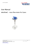
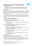
IO-LinkParameter FM-IM / FMX-IM Strömungsüberwachung Flow Monitoring Sense it! Connect it! Bus it! Solve it! Parameterliste IO-Link für FM-IM / FMX-IM 1 1 1.1 1.2 1.3 1.4 Allgemeine Hinweise 2 Bestimmungszweck des Dokuments 2 Erklärung zu den verwendeten Symbolen 2 TURCK-Service2 Zugehörige Unterlagen 3 2 2.1 2.2 2.3 2.4 2.5 Sicherheitshinweise3 Allgemeine Hinweise 3 Bestimmungsgemäße Verwendung 3 Qualifiziertes Personal 3 Restgefahren3 CE-Konformität3 3 3.1 Gerätebeschreibung4 Softwaregestützte IO-Link-Parametrierung 4 4 4.1 Elektrischer Anschluss 5 Blockschaltbilder6 5 Allgemeine Parameterdaten 7 6 Prozessdaten (zyklische Kommunikation) 7 7 7.1 7.2 Azyklische Kommunikation (via ORDO) 8 Allgemeine8 Spezifische9 8 Fehlermeldungen12 Hans Turck GmbH & Co. KG • Tel. +49 (0) 208/4952-0 • Fax +49 (0) 208/4952-264 Allgemeine Hinweise 1 Allgemeine Hinweise 1.1 Bestimmungszweck des Dokuments 1.2 Parameterliste IO-Link Diese Anleitung beschreibt den Anschluss und die Parametrierung von Auswertegeräten der FM(X)-Baureihe mit IO-Link. Enthalten sind die Beschreibung des Betriebs über IO-Link, Informationen zu den verfügbaren Funktionen und eine Auflistung aller für den Betrieb notwendigen Parameter. Erklärung zu den verwendeten Symbolen In dieser Anleitung werden folgende Symbole verwendet: GEFAHR Wahrscheinliche Personenschäden mit Todesfolge Mit ganz besonderer Vorsicht vorgehen. Dieses Zeichen steht neben Warnhinweisen, die auf eine potenzielle Gefahrenquelle hindeuten. Bei Nichtbeachtung sind Personenschäden oder Tod sehr wahrscheinlich. HINWEIS Dieses Zeichen steht neben allgemeinen Hinweisen, die auf wichtige Informationen zum Vorgehen hinsichtlich eines oder mehrerer Arbeitsschritte hinweisen. Die betreffenden Hinweise können die Arbeit erleichtern und zum Beispiel helfen, Mehrarbeit durch falsches Vorgehen zu vermeiden. TECHNISCHE GRUNDLAGEN Dieses Zeichen steht neben technischen Informationen, die Grundlagen und Hintergrundwissen vermitteln sollen. Diese Informationen führen zum besseren Verständnis von Arbeitsweisen der Geräte. Der routinierte Anwender kann diese Informationen übergehen. HANDLUNGSAUFFORDERUNG ➤ Dieses Zeichen kennzeichnet Handlungsschritte, die der Anwender auszuführen hat. 1.3 TURCK-Service Ergänzend zu den Produkten bietet TURCK einen umfassenden Support. Die Produktdatenbank unter www.turck.de/produkte umfasst einen Gesamtüberblick des Produktportfolios mit Gerätekurzbeschreibungen und jeweils einen Überblick über ergänzende Produkte. Es stehen weiterhin alle gerätespezifischen Informationen wie Flyer, Kataloge, Handbücher, Bescheinigungen und CAD-Daten zum kostenlosen Download zur Verfügung. Anwendungs- und Betriebssoftware für verschiedene Applikationen ist unter dem Register „Software“ zum kostenlosen Download verfügbar. Bei weiteren Fragen ist das Sales & Service-Team in Deutschland unter folgenden Servicenummern zu erreichen und wird Sie an den entsprechenden Spezialisten weiterleiten. Aus dem Ausland wenden Sie sich an Ihre Landesvertretung (Adressen auf der Dokumentrückseite): ■■Vertrieb: +49 (0) 208 4952-380 ■■Technik: +49 (0) 208 4952-390 ■■E-Mail: [email protected] HINWEIS Geräterücksendung Ist die Rücksendung eines Geräts nötig, so können nur Geräte entgegengenommen werden, die mit einer Dekontaminationserklärung versehen sind. Diese steht unter http://www.turck.de/de/support_download.asp zum Download zur Verfügung und muss vollständig ausgefüllt, wetter- und transportsicher an der Außenseite der Verpackung angebracht sein. [email protected] • www.turck.com • 2012/06 2 Parameterliste IO-Link für FM-IM / FMX-IM 1.4 Zugehörige Unterlagen Ergänzend zu diesem Dokument sind die folgenden Dokumente als PDF in der Produktdatenbank zum Download verfügbar: ■■Betriebsanleitung – FM-IM / FMX-IM ■■Getting started – FDT/DTM Frame PACTware™ with IO-Link (D101931) 2 Sicherheitshinweise Jede Person, die mit der Inbetriebnahme oder Bedienung dieses Gerätes beauftragt ist, muss die Betriebsanleitung und insbesondere die Sicherheitshinweise gelesen und verstanden haben. 2.1 Allgemeine Hinweise Zur Gewährleistung eines sicheren Betriebs darf das Gerät nur nach den Angaben in der Betriebsanleitung betrieben werden. Bei der Verwendung des Gerätes sind zusätzlich die für den jeweiligen Anwendungsfall erforderlichen Rechts- und Sicherheitsvorschriften zu beachten. Sinngemäß gelten die erforderlichen Rechts- und Sicherheitsvorschriften auch bei der Verwendung von Zubehör. 2.2 Bestimmungsgemäße Verwendung Die Geräte dienen zur Anzeige und Überwachung von Prozessgrößen. Werden die Geräte anderweitig genutzt, gilt dies als nicht bestimmungsgemäß. Die Geräte dürfen nicht als alleiniges Mittel zur Abwendung gefährlicher Zustände an Maschinen und Anlagen eingesetzt werden. Maschinen und Anlagen müssen so konstruiert werden, dass fehlerhafte Zustände nicht zu einer für das Bedienpersonal gefährlichen Situation führen können (z. B. durch unabhängige Grenzwertschalter, mechanische Verriegelungen, etc.). 2.3 Qualifiziertes Personal Die Geräte dürfen nur von qualifiziertem Personal ausschließlich entsprechend der technischen Daten verwendet werden. Qualifiziertes Personal sind Personen, die mit der Aufstellung, Montage, Inbetriebnahme und Betrieb der Geräte vertraut sind und die über eine ihrer Tätigkeit entsprechenden Qualifikation verfügen. 2.4 Restgefahren Die Geräte entsprechen dem Stand der Technik und sind betriebssicher. Von den Geräten können Restgefahren ausgehen, wenn die Geräte von ungeschultem Personal unsachgemäß eingesetzt und bedient werden. 2.5 CE-Konformität Die Geräte entsprechen der EN 61326 und dürfen nur im Industriebereich eingesetzt werden. Die Konformitätserklärung ist in der Produktdatenbank unter den gerätespezifischen Informationen zum Download verfügbar. 3 Hans Turck GmbH & Co. KG • Tel. +49 (0) 208/4952-0 • Fax +49 (0) 208/4952-264 Gerätebeschreibung 3 Gerätebeschreibung 3.1 Parameterliste IO-Link Die Auswertegeräte der Baureihe FM(X) dienen zur Strömungs- und Temperaturüberwachung von Fluiden und Gasen und sind für den Einsatz mit Strömungssensoren konzipiert. Die Auswertegeräte FM(X)-IM-3UP63X, FM(X)-IM-3UR38X und FM-IM-2UPLi63X sind mit dem Kommunikationsprotokoll IO-Link ausgestattet. Softwaregestützte IO-Link-Parametrierung HINWEIS Sperrung im tastengeführten Menü Für den Zeitraum, in dem das Auswertegerät über IO-Link kommuniziert, ist das tastengeführte Menü gesperrt, d. h. die Parameter können über die Tasten nicht mehr verändert werden. Ein Abrufen der Prozesswerte über die Tasten ist aber möglich. Die Ports des IO-Link-Masters können im IO-Link-Modus (IOL) oder im Standard-IO-Modus (SIO) konfiguriert sein. Ist ein Port im SIO-Modus konfiguriert, verhält sich der IO-Link-Master an diesem Port wie ein normaler digitaler Eingang und das angeschlossenen IO-Link-Gerät (hier FM-IM/FMX-IM) übermittelt seinen klassischen Schaltausgang an den IOLink Master – es findet keinerlei Kommunikation zwischen dem Gerät und dem Master statt. Ist der Port im IOL-Modus konfiguriert, versucht der IO-Link Master das angeschlossene IO-Link-Gerät über den „Wake-up Request“ aufzuwecken. Empfängt der Master eine Antwort vom Auswertegerät, fangen beide Geräte an miteinander zu kommunizieren. Zuerst werden die Kommunikationsparameter (communication parameter) ausgetauscht, anschließend beginnt der zyklische Datenaustausch der Prozessdaten (Process Data Objects). Bei zyklischer Kommunikation erfolgt die Datenübertragung nach dem in Kapitel 6 auf S. 7 aufgezeigten Prozessdatenbild: Im Falle der aktiven IO-Link-Kommunikation (IOL-Modus) steht neben dem zyklischen auch ein azyklischer Kommunikationsdienst zur Verfügung. Die Parametrierung via IO-Link kann über unterschiedliche Wege erfolgen: ■■über On-request Data Objects (z. B. steuerungsnah über IO-Link-Funktionsbaustein), ■■über toolbasiertem Engineering über FDT/DTM (z. B. PACTware™ unter Verwendung des DTM bzw. der IODD) TECHNISCHE GRUNDLAGEN Geräte-Parameter (On-request Data Objects) Geräte-Parameter werden azyklisch und auf die Anfrage des IO-Link-Masters ausgetauscht. Der IO-Link-Master sendet immer zuerst eine Anfrage an das Gerät, dann antwortet das Gerät. Das gilt sowohl für das Schreiben der Daten ins Gerät als auch das Lesen der Daten aus dem Gerät. Mit Hilfe der On-request Data Objects (ORDO) können Parameterwerte ins Gerät geschrieben (Write) oder Gerätezustände aus dem Gerät ausgelesen (Read) werden. [email protected] • www.turck.com • 2012/06 4 Parameterliste IO-Link für FM-IM / FMX-IM 4 Elektrischer Anschluss Der Leitungsanschluss erfolgt über verpolsichere Klemmenblöcke mit unverlierbaren Schrauben für die Anschlussquerschnitte ≤ 1 × 2,5 mm2, 2 × 1,5 mm2 oder 2 × 1 mm2 mit Ader-Endhülsen. GEFAHR Gefährliche Spannung an den Anschlussklemmen Unmittelbar mögliche Personenschäden bei den Geräten FM-IM-3UR38X und FMX-IM-3UR38X ➤➤Beachten Sie die einschlägigen Sicherheitsvorschriften beim Anschluss. HINWEIS Abstände zwischen Gerät und Sensor Die Länge der elektrischen Verbindung zwischen dem Strömungssensor und dem Gerät darf maximal 100 m betragen. Bei Längen über 30 m wird eine geschirmte Sensorleitung empfohlen. In jedem Fall ist zu prüfen, ob der gewählte Aderquerschnitt den Anforderungen entspricht. Funktion FM(X)-IM-3UP63X FM(X)-IM-3UR38X FM-IM-2UPLi63X Sensorversorgung Klemme 1 Klemme 1 Klemme 1 geheizter Pt1000 Klemme 2 Klemme 2 Klemme 2 GND Klemme 3 Klemme 3 Klemme 3 ungeheizter Pt1000 Klemme 4 Klemme 4 Klemme 4 Spannungsversorgung Klemme 19 (+) Klemme 19 (+) Klemme 19 (+) Klemme 20 (−) Klemme 20 (−) Klemme 20 (−) PNP 1 (Out 1) Klemme 12 PNP 2 (Out 2) Klemme 13 Klemme 13 PNP 3 (Out 3) Klemme 14 Klemme 14 Relais 1 (Out 1) Klemmen 12 und 13 Relais 2 (Out 2) Klemmen 14 und 15 Relais 3 (Out 3) Klemmen 17 und 18 Stromquelle Klemme 11 (+) Klemme 16 (−) IO-Link Tabelle 1 5 Klemme 12, alternativ über Buchse COM (PC) über Buchse COM (PC) Klemme 12, alternativ über Buchse COM (PC) Klemmenbelegung Hans Turck GmbH & Co. KG • Tel. +49 (0) 208/4952-0 • Fax +49 (0) 208/4952-264 Elektrischer Anschluss Blockschaltbilder FM-IM-3UP63X FMX-IM-3UP63X 2 3 4 BN COM (PC) 2 BU 1 12 –3 BK FMX-IM-3UR38X +1 WH FM-IM-3UR38X 1 Parameterliste IO-Link 4.1 YE 4 15 17 RD 18 19 + Pwr GN 3 13 14 YE 2 1 Flow 20 – 2 Temp ≤ 250 VAC/ 125 VDC ≤ 500 VA/60 W ≤2A 4 BN WH BU BK +1 COM (PC) 2 12 –3 YE 4 14 YE 20...250 VAC 20...125 VDC 15 17 3 Fault RD 18 19 + Pwr GN 1 Flow 13 20 – 2 Temp ≤ 250 VAC/ 125 VDC ≤ 500 VA/60 W ≤2A 3 Fault 20...250 VAC 20...125 VDC FM-IM-2UPLi63X Abbildung 1 Blockschaltbilder der IO-Link-Geräte [email protected] • www.turck.com • 2012/06 6 Parameterliste IO-Link für FM-IM / FMX-IM 5 Allgemeine Parameterdaten Index Index (dez.) (hex.) Name Zugriff ByteFormat Beschreibung länge Vendor name 16 0x10 Read 32 Hersteller ID, fest: „Turck” Vendor text 17 0x11 Read 32 fest: “www.turck.com” Product name 18 0x12 Read 32 Typenbezeichnung, fest: z. B. „FM-IM-3UP63X“ Product ID 19 0x13 Read 16 Geräte ID, fest: z. B. „ 7525100“ Product text 20 0x14 Read 32 fest: “Stroemungsueberwachung ” Serial number 21 0x15 Read 16 Chargencode und laufende Chargennummer Firmware revision 23 0x17 Read 16 Aktueller Firmwarestand (3-Punkt-Notation), z.B. “1.1.4.1“ Application specific name 24 0x18 Read/ Write 16 Default: „-“, maximal 16 Byte durch Kunden beschreibbar 6 Prozessdaten (zyklische Kommunikation) Name Process data Index Index (dez.) (hex.) Zugriff BitaufBitWert Format teilung länge 16 0 0 Schaltzustand Out 1 (Flow): aus / offen 1 Schaltzustand Out 1 (Flow): ein / geschlossen 1 0 Schaltzustand Out 2 (Temp): aus / offen 1 Schaltzustand Out 2 (Temp): ein / geschlossen 2 0 Schaltzustand Out 3 (Fault ): aus / offen 1 Schaltzustand Out 3 (Fault): ein / geschlossen 0…1023 Prozesswert 0…100 % 3…5 6…15 7 Beschreibung nicht belegt Hans Turck GmbH & Co. KG • Tel. +49 (0) 208/4952-0 • Fax +49 (0) 208/4952-264 7 Azyklische Kommunikation (via ORDO) 7.1 Allgemeine Name Systembefehle Index Index (dez.) (hex.) 80 IO-Link Kommunikation sperren / freigeben 89 Temperaturgradient (DeltaFlow) 145 Teach Status Erweiterte Diagnose 146 304 0x50 0x59 0x91 0x92 0x0130 Zugriff Write BitaufBitWert Format teilung länge 8 Read/ Write 8 Read 16 Read Read [email protected] • www.turck.com • 2012/06 8 64 uint8 Hardware Reset 130 Werkseinstellungen wiederherstellen 0 IO-Link Parametrierung nicht möglich 1 IO-Link Parametrieung möglich 0…9 0…1023 DeltaFlow [0…1023 Bit] 10…11 0 DeltaFlow hinreichend gering 1 DeltaFlow niedrig 2 DeltaFlow mittel uint8 flag Beschreibung 128 uint8 Parameterliste IO-Link On-request Data Objects (ORDO) 3 DeltaFlow hoch 0 Teachfunktion freigegeben 1 Teachfunktion nicht freigegeben 0 DeltaFlow zu groß 2 Kurzschluss DOut 1 (Flow) (nur FM(X)-IM3UP63X) 3 Kurzschluss DOut 2 (Temp) (nur FM(X)-IM-3UP63X und FM-IM-2UPLi63X) 4 Kurzschluss DOut 3 (Fault) (nur FM(X)-IM-3UP63X und FM-IM-2UPLi63X) 5 Kurschluss Sensor 6 Drahtbruch Sensor 7 Drahtbruch Stromquelle 8 Genereller Fehler (manueller Reset nötig) 10 Software-Fehler 11 Hardware-Fehler 12 DOut 1 (Flow) ein / geschlossen (nur FM(X)-IM3UP63X und FM(X)-IM-3UR38X) 13 DOut 2 (Temp) ein /geschlossen 14 DOut 3 (Fault) ein / geschlossen 16 Ausgangsstrom im Fehlerfall zur Zeit aktiv 17 Force-Modus aktiv fü für AOut (nur FM-IM-2UPLi63X) 18 Bürde zu hoch oder Stromquelle defekt (Abschaltung der Stromquelle, Power-Reset nötig) 25 Force-Modus aktiv für DOut 32 Bereich zwischen MIN und MAX zu gering 33 Strömung oberhalb Anzeigebereich 34 Strömung unterhalb Anzeigebereich 35 Strömung oberhalb Arbeitsbereich 36 Temperatur oberhalb Anzeigebereich 37 Temperatur unterhalb Anzeigebereich 38 Temperatur oberhalb Arbeitsbereich 39 Temperatur unterhalb Arbeitsbereich 8 Parameterliste IO-Link für FM-IM / FMX-IM 7.2 Spezifische FM(X)-IM-3UP63X Name Zugriff BitaufBitWert Format teilung länge Beschreibung Ausgangsart Flow (SP1) 97 0x61 Read/ Write 8 uint8 1 2 PNP 1 Schalteigenschaft „active low“ Ausgangsart Temp (SP2) 98 0x62 Read/ Write 8 uint8 1 PNP 2 Schalteigenschaft „active high“ 2 PNP 2 Schalteigenschaft „active low“ Teachmodus 100 Write 8 1 obere Grenze (MAX) einlernen 2 untere Grenze (MIN) einlernen QuickTeach % aendern 101 0x64 0x65 Read/ Write 8 uint8 uint8 PNP 1 Schalteigenschaft „active high“ 3 Quick-Teach 2 4,50 % unter aktuellen Flow-Wert 3 3,00 % unter aktuellen Flow-Wert 4 1,50 % unter aktuellen Flow-Wert 5 0% (aktuellen Flow-Wert als SP Flow annehmen) 6 1,50 % über aktuellen Flow-Wert 7 3,00 % über aktuellen Flow-Wert 8 4,50 % über aktuellen Flow-Wert 9 6,00 % über aktuellen Flow-Wert Quick-Teach-Modus Betriebsmodus 102 0x66 Read/ Write 8 uint8 1 2 MAX/MIN-Abgleich Stroemungsgeschwindigkeit 112 0x70 Read 16 uint16 0…1023 Prozesswert Flow 0 … 100 % 0 = 0% … 1023 = 100% Medientemperatur 113 0x71 Read 16 int16 -50…200 Temperatur −50 … 200 °C [1 °C Schritte] Schaltpunkt Flow (SP1) 129 0x81 Read/ Write 8 uint8 0…100 Schaltpunkt Flow (Out 1) 0 … 100 % [1 % Schritte] Schaltpunkt Temp (SP2) 130 0x82 Read/ Write 16 int16 -50…200 Schaltpunkt Temp (Out 2) −50 … 200 °C [1 °C Schritte] Einschaltverzoegerung Flow (SP1) 150 0x96 Read/ Write 8 uint8 0…255 PNP 1 Einschaltverzögerung 0 = 0,0 s … 255 = 25,5 s Einschaltverzoegerung Temp (SP2) 151 0x97 Read/ Write 8 uint8 0…255 PNP 2 Einschaltverzögerung 0 = 0,0 s … 255 = 25,5 s Einschaltverzoegerung Fault (SP3) 152 0x98 Read/ Write 8 uint8 0…255 PNP 3 Einschaltverzögerung 0 = 0,0 s … 255 = 25,5 s Ausschaltverzoegerung Flow (SP1) 153 0x99 Read/ Write 8 uint8 0…255 PNP 1 Ausschaltverzögerung 0 = 0,0 s … 255 = 25,5 s Ausschaltverzoegerung Temp (SP2) 154 0x9A Read/ Write 8 uint8 0…255 PNP 2 Ausschaltverzögerung 0 = 0,0 s … 255 = 25,5 s Ausschaltverzoegerung Fault (SP3) 155 0x9B Read/ Write 8 uint8 0…255 PNP 3 Ausschaltverzögerung 0 = 0,0 s … 255 = 25,5 s Schaltausgänge (Force-Modus) 300 0x012C Write 8 uint8 0x11 alle PNP-Ausgänge aus 0x13 PNP-Ausgang Out 1 ein 0x15 PNP-Ausgang Out 2 ein 0x19 PNP-Ausgang Out 3 ein Prozesswerte MAX/MIN-Teach 9 Index Index (dez.) (hex.) 994 0x03E2 Read/ Write 32 2× uint16 0x00 Force Modus aus 0…15 0…1023 MIN Teachwert [Bit] 16…31 0…1023 MAX Teachwert [Bit] Hans Turck GmbH & Co. KG • Tel. +49 (0) 208/4952-0 • Fax +49 (0) 208/4952-264 On-request Data Objects (ORDO) FM(X)-IM-3UR38X Index Index (dez.) (hex.) Ausgangsart Flow (SP1) 97 Ausgangsart Temp (SP2) 98 Teachmodus 100 QuickTeach % aendern Betriebsmodus Stroemungsgeschwindigkeit 101 102 112 0x61 0x62 0x64 0x65 0x66 0x70 Zugriff BitaufBitWert Format teilung länge Read/ Write 8 Read/ Write 8 Write 8 Read/ Write 8 Read/ Write 8 Read 16 uint8 uint8 uint8 uint8 uint8 uint16 Beschreibung 1 Relais 1 Schalteigenschaft „Schließer (NO)“ 2 Relais 1 Schalteigenschaft „Öffner (NC)“ 1 Relais 2 Schalteigenschaft „Schließer (NO)“ 2 Relais 2 Schalteigenschaft „Öffner (NC)“ 1 obere Grenze (MAX) einlernen 2 untere Grenze (MIN) einlernen 3 Quick-Teach 2 4,50 % unter aktuellen Flow-Wert 3 3,00 % unter aktuellen Flow-Wert 4 1,50 % unter aktuellen Flow-Wert 5 0% (aktuellen Flow-Wert als SP Flow annehmen) 6 1,50 % über aktuellen Flow-Wert 7 3,00 % über aktuellen Flow-Wert 8 4,50 % über aktuellen Flow-Wert 9 6,00 % über aktuellen Flow-Wert 1 Quick-Teach-Modus 2 MAX/MIN-Abgleich 0…1023 Prozesswert Flow 0 … 100 % 0 = 0% … 1023 = 100% Medientemperatur 113 0x71 Read 16 int16 -50…200 Temperatur −50 … 200 °C [1 °C Schritte] Schaltpunkt Flow (SP1) 129 0x81 Read/ Write 8 uint8 0…100 Schaltpunkt Flow (Out 1) 0 … 100 % [1 % Schritte] Schaltpunkt Temp (SP2) 130 0x82 Read/ Write 16 int16 -50…200 Schaltpunkt Temp (Out 2) −50 … 200 °C [1 °C Schritte] Einschaltverzoegerung Flow (SP1) 150 0x96 Read/ Write 8 uint8 0…255 Relais 1 Einschaltverzögerung 0 = 0,0 s … 255 = 25,5 s Einschaltverzoegerung Temp (SP2) 151 0x97 Read/ Write 8 uint8 0…255 Relais 2 Einschaltverzögerung 0 = 0,0 s … 255 = 25,5 s Einschaltverzoegerung Fault (SP3) 152 0x98 Read/ Write 8 uint8 0…255 Relais 3 Einschaltverzögerung 0 = 0,0 s … 255 = 25,5 s Ausschaltverzoegerung Flow (SP1) 153 0x99 Read/ Write 8 uint8 0…255 Relais 1 Ausschaltverzögerung 0 = 0,0 s … 255 = 25,5 s Ausschaltverzoegerung Temp (SP2) 154 0x9A Read/ Write 8 uint8 0…255 Relais 2 Ausschaltverzögerung 0 = 0,0 s … 255 = 25,5 s Ausschaltverzoegerung Fault (SP3) 155 0x9B Read/ Write 8 uint8 0…255 Relais 3 Ausschaltverzögerung 0 = 0,0 s … 255 = 25,5 s Schaltausgänge (Force-Modus) 300 0x012C Write 8 uint8 0x11 alle Relais-Ausgänge aus 0x13 Relais-Ausgang Out 1 ein 0x15 Relais-Ausgang Out 2 ein 0x19 Relais -Ausgang Out 3 ein 0x00 Force Modus aus Prozesswerte MAX/MIN-Teach 994 0x03E2 Read/ Write [email protected] • www.turck.com • 2012/06 32 2× uint16 0…15 0…1023 MIN Teachwert [Bit] 16…31 0…1023 MAX Teachwert [Bit] Parameterliste IO-Link Name 10 Parameterliste IO-Link für FM-IM / FMX-IM FM-IM-2UPLi63X Name 11 Index Index (dez.) (hex.) Ausgangsart Temp (SP2) 98 Teachmodus 100 0x62 0x64 Zugriff BitaufBitWert Format teilung länge Read/ Write 8 Write 8 uint8 uint8 Beschreibung 1 PNP 2 Schalteigenschaft „active high“ 2 PNP 2 Schalteigenschaft „active low“ 1 obere Grenze (MAX) einlernen 2 untere Grenze (MIN) einlernen Betriebsmodus 102 0x66 Read/ Write 8 uint8 2 MAX/MIN-Abgleich Stroemungsgeschwindigkeit 112 0x70 Read 16 uint16 0…1023 Prozesswert Flow 0 … 100 % 0 = 0% … 1023 = 100% Medientemperatur 113 0x71 Read 16 int16 -50…200 Temperatur −50 … 200 °C [1 °C Schritte] Schaltpunkt Temp 130 0x82 Read/ Write 16 int16 -50…200 Schaltpunkt Temp (Out 2) −50 … 200 °C [1 °C Schritte] Einschaltverzoegerung Temp (SP2) 151 0x97 Read/ Write 8 uint8 0…255 PNP 2 Einschaltverzögerung 0 = 0,0 s … 255 = 25,5 s Einschaltverzoegerung Fault (SP3) 152 0x98 Read/ Write 8 uint8 0…255 PNP 3 Einschaltverzögerung 0 = 0,0 s … 255 = 25,5 s Ausschaltverzoegerung Temp (SP2) 154 0x9A Read/ Write 8 uint8 0…255 PNP 2 Ausschaltverzögerung 0 = 0,0 s … 255 = 25,5 s Ausschaltverzoegerung Fault (SP3) 155 0x9B Read/ Write 8 uint8 0…255 PNP 3 Ausschaltverzögerung 0 = 0,0 s … 255 = 25,5 s Schaltausgänge (Force-Modus) 300 0x012C Write 8 uint8 0x11 alle PNP-Ausgänge aus 0x15 PNP-Ausgang Out 2 ein 0x19 PNP-Ausgang Out 3 ein 0x00 Force Modus aus 0…1023 MIN Teachwert [Bit] Prozesswerte MAX/MIN-Teach 994 0x03E2 Read/ Write 32 2× uint16 0…1023 MAX Teachwert [Bit] Stromquelle (Analog) 995 0x03E3 Read 16 uint16 0…25000 Ausgangsstrom 0 … 25,0 mA [1 µA Schritte] Ausgangsstrom im Fehlerfall 997 0x03E5 Read/ Write 8 uint8 1 Ausgangsstrom im Fehlerfall 0 mA 2 Ausgangsstrom im Fehlerfall > 22 mA Ausgangsstrombeireich 998 Read/ Wrtite 8 1 4 … 20 mA 3 20 … 4 mA Stromquelle (Force-Modus) 999 Write 16 0 Force Modus aus 1…25000 Ausgangsstrom 0,1 … 25,0 mA [1 µA Schritte] 0x03E6 0x03E7 uint8 uint16 0…15 16…31 Hans Turck GmbH & Co. KG • Tel. +49 (0) 208/4952-0 • Fax +49 (0) 208/4952-264 Fehlermeldungen Fehlermeldungen Name Fehlermeldungen Index Index (dez.) (hex.) 144 0x90 Zugriff Read [email protected] • www.turck.com • 2012/06 BitaufBitWert Format teilung länge 16 Beschreibung 0 Bereich zwischen MIN und MAX zu gering 1 Strömung oberhalb Anzeigebereich 2 Strömung unterhalb Anzeigebereich 3 Strömung oberhalb Arbeitsbereich 4 Temperatur oberhalb Anzeigebereich 5 Temperatur unterhalb Anzeigebereich 6 Temperatur oberhalb Arbeitsbereich 7 Temperatur unterhalb Arbeitsbereich 8 Drahtbruch Sensor 9 Kurzschluss Sensor 10 Kurzschluss PNP-Out 1 (Flow) (nur FM(X)-IM-3UP63X) 11 Kurzschluss PNP-Out 2 (Temp) (nur FM(X)-IM-3UP63X und FM-IM2UPLi63X) 12 Kurzschluss PNP-Out 3 (Fault) (nur FM(X)-IM-3UP63X und FM-IM2UPLi63X) 13 Genereller Fehler (manueller Reset nötig) 14 Drahtbruch Stromquelle 15 Bürde zu hoch oder Stromquelle defekt (Abschaltung der Stromquelle, Power-Reset nötig) Parameterliste IO-Link 8 12 Parameter list IO-Link for FM-IM / FMX-FM 1 1 1.1 1.2 1.3 1.4 General instructions 2 Intended purpose of this document 2 Explanation of the used symbols 2 TURCK-service2 Additional documents 3 2 2.1 2.2 2.3 2.4 2.5 Safety instructions 3 General instructions 3 Intended use 3 Qualified personnel 3 Residual risks 3 CE-conformity3 3 3.1 Device description Software-supported IO-Link-Parameterization 4 4 4 4.1 Electrical connection Block diagram 5 6 5 General parameters 7 6 Process data (cyclic communication) 7 7 7.1 7.2 Acyclic communication (via ORDO) 8 General8 Specific9 8 Fault messages 12 Hans Turck GmbH & Co. KG • Tel. +49 (0) 208/4952-0 • Fax +49 (0) 208/4952-264 General instructions 1 General instructions 1.1 Intended purpose of this document This manual describes the connection and basic operation of signal processors of the FM(X)-series, together with IO-Link. It contains the operation via IO-Link, information about IO-Link functions. and a list of all required IO-Link parameters. 1.2 Explanation of the used symbols This instruction manual contains the following symbols: DANGER Probable personal injuries resulting in death Proceed with extra special care. This symbol is next to a warning which points to a potential source of danger. It is very likely that noncompliance will result in personal injuries or death. IMPORTANT INFORMATION This symbol is next to general information that points to important step-by-step work instructions. The respective information and instructions can simplify the work; for example, it may help prevent additional work caused by proceeding with the wrong step. BASIC TECHNICAL INFORMATION Parameter list IO-Link This symbol is next to technical information to explain basic principles and background knowledge. This information leads to better understanding of how the devices operate. The experienced user may convey this information. CALL FOR ACTION ➤ This symbol identifies action steps that the user must complete. 1.3 TURCK-service In addition to the products, TURCK offers comprehensive product support services. The product database under www.turck.de/products provides a comprehensive overview of the product portfolio, together with short descriptions of devices and a respective overview of complementary products. Device-specific information like flyers, catalogs, handbooks, certifications, and CAD-data continue to be available via free downloads. User and operating software for different applications can be downloaded for free under the Register “Software”. For additional questions, please contact the Sales & Service Team in Germany under the following service phone numbers so that you may be connected with the respective specialist. Outside of Germany, please contact the representative in your country (find addresses on the back cover of the documentation): ■■Sales: +49 (0) 208 4952-380 ■■Application Support: +49 (0) 208 4952-390 ■■E-mail: [email protected] IMPORTANT INFORMATION Return of device If a device must be returned, only devices with a decontamination declaration can be accepted. Please download the decontamination declaration form under http://www.turck.de/en/support_download.asp, complete it, place it in a protective envelope suitable for shipping, and attach it on the outside packaging. [email protected] • www.turck.com • 2012/06 2 Parameter list IO-Link for FM-IM / FMX-FM 1.4 Additional documents In addition and complimentary to this documentation, the following documents are available as PDF versions in the product database for download. ■■Instruction manual FM-IM / FMX-IM ■■Getting started – FDT/DTM Frame PACTware™ with IO-Link (D101931) 2 Safety instructions Each person, who is responsible for the start-up and operation of this device, must have read and understood the instruction manual and specifically the safety instructions. 2.1 General instructions In order to ensure safe operation, the device must only be operated according to the instructions in the instruction manual. When operating the device, the required laws and safety regulations must also be followed in connection with each respective application. In this context, the required laws and safety regulations are also valid when using accessories. 2.2 Intended use The devices are used to indicate and monitor process factors. If the devices are used in an ulterior way, this is a violation of the intended use. The devices must not be used as the only means to prevent dangerous situations on machines and installations. Machines and installations must be designed in such a way, that flawed conditions can not lead to a situation that is dangerous for operators (e.g., with the help of independent limit switches, mechanical locks, etc.). 2.3 Qualified personnel The devices must only be operated by qualified personnel and only according to the respective technical specifications. Qualified personnel are persons who are familiar with the assembly, installation, start-up, and operation of the devices and who have the respective occupational qualification. 2.4 Residual risks The devices are state-of-the-art and are operationally reliable. Residual risks may stem from the devices when they are used and operated in a way that is unintended and by untrained personnel. 2.5 CE-conformity The devices meet EN 61326 and may only be used in industrial applications. The declaration of conformity can be found in the product database under the device-specific information for download. 3 Hans Turck GmbH & Co. KG • Tel. +49 (0) 208/4952-0 • Fax +49 (0) 208/4952-264 Device description 3 Device description The signal processors of the FM(X)-series are used to monitor flow and temperature of fluids and gases and are designed to be used together with flow sensors. All TURCK flow sensors of the series FCS-…-NA (immersion sensors) and FCI-…-NA (inline sensors) can be operated without any limitations. 3.1 Software-supported IO-Link-Parameterization IMPORTANT INFORMATION Locking in the pushbutton guided menu During the time the data processing device communicates via IO-Link, the pushbutton-guided menu is locked; this means, the parameters can no longer be changed via the pushbuttons. However, the process values can be accessed via the pushbuttons. The ports of the IO-Link-Master can be configured in the IO-Link-Mode (IOL) or in the Standard-IO-Mode. If a port is configured in the SIO-Mode, the IO-Link-Master on this port behaves like a normal digital input and the connected IO-Link device (here FM-IM/FMX-IM) sends the standard switching output to the IO-Link-Master – there is no communication between the device and the master. Parameter list IO-Link If the port is configured in the IOL-Mode, the IO-Link-Master tries to wake the connected IO-Link-device via the“Wake-up Request”. If the master receives a response from the signal processor, both devices start to communicate with each other. First, the communication parameters are exchanged; then the cyclic data exchange of the process data (Process Data Objects) starts. With cyclic communication, the data is transmitted according to the process data image shown in Chapter 6 on p. 7. In case of active IO-Link-communication (IOL-Mode), both cyclic and acyclic communication services are available. Parameterization via IO-Link can occur in different ways: ■■via On-request Data Objects (e. g., IO-Link-function block close to the control), ■■via tool-based engineering via FDT/DTM (e.g., PACTware™ with the use of DTM or the IODD) BASIC TECHNICAL INFORMATION Device parameters (On-request Data Objects) Device parameters are exchanged in an acyclical manner and upon the request of the IO-Link-Master. The IO-Link-Master always sends a request to the device first, then the device responds. This is the case when the data is written into the device and read from the device. With the help of the On-Request Data Objects (ORDO), the parameters can be written into the device (Write) or the device status can be read from the device (Read). [email protected] • www.turck.com • 2012/06 4 Parameter list IO-Link for FM-IM / FMX-FM 4 Electrical connection The cable is connected via reverse polarity protected terminal blocks with undetachable screws for the connection widths ≤ 1 × 2.5mm², 2 × 1.5mm² or 2 × 1mm² with wire end sleeve. DANGER Dangerous voltages on the connection terminals Instantaneously possible personal injuries with devices FM-IM-3UR38X and FMX-IM-3UR38X ➤➤Please adhere to the respective safety regulations during connection. IMPORTANT INFORMATION Distances between device and sensor The length of the electrical connection between the flow sensor and the device may be max. 100 m. With lengths exceeding 30 m a shielded sensor cable is recommended. In either case it should be checked whether the chosen wire width meets the requirements. Function FM(X)-IM-3UP63X FM(X)-IM-3UR38X FM-IM-2UPLi63X Sensor Supply Terminal 1 Terminal 1 Terminal 1 heated Pt1000 Terminal 2 Terminal 2 Terminal 2 GND Terminal 3 Terminal 3 Terminal 3 unheated Pt1000 Terminal 4 Terminal 4 Terminal 4 Voltage Supply Terminal 19 (+) Terminal 19 (+) Terminal 19 (+) Terminal 20 (−) Terminal 20 (−) Terminal 20 (−) PNP 1 (Out 1) Terminal 12 PNP 2 (Out 2) Terminal 13 Terminal 13 PNP 3 (Out 3) Terminal 14 Terminal 14 Relay 1 (Out 1) Terminals 12 and 13 Relay 2 (Out 2) Terminals 14 and 15 Relay 3 (Out 3) Terminals 17 and 18 Current Source Terminal 11 (+) Terminal 16 (−) IO-Link Table 1 5 Terminal 12, alternative via female connector COM (PC) via female connector COM (PC) Terminal 12, alternative via female connector COM (PC) Terminal assignment Hans Turck GmbH & Co. KG • Tel. +49 (0) 208/4952-0 • Fax +49 (0) 208/4952-264 Electrical connection Block diagram FM-IM-3UP63X FMX-IM-3UP63X 2 3 4 BN COM (PC) 2 BU 1 12 –3 BK FMX-IM-3UR38X +1 WH FM-IM-3UR38X 1 YE 4 15 17 RD 18 19 + Pwr GN 3 13 14 YE 2 1 Flow 20 – 2 Temp ≤ 250 VAC/ 125 VDC ≤ 500 VA/60 W ≤2A 4 BN WH BU BK +1 COM (PC) 2 12 –3 YE 4 14 YE 20...250 VAC 20...125 VDC 15 17 3 Fault RD 18 19 + Pwr GN 1 Flow 13 20 – 2 Temp ≤ 250 VAC/ 125 VDC ≤ 500 VA/60 W ≤2A Parameter list IO-Link 4.1 3 Fault 20...250 VAC 20...125 VDC FM-IM-2UPLI63X Figure 1 Block diagrams IO-Link devices [email protected] • www.turck.com • 2012/06 6 Parameter list IO-Link for FM-IM / FMX-FM 5 General parameters Index Index (dec.) (hex.) Name Access Byte Type count Description Vendor name 16 0x10 Read 32 Manufacturer ID , fixed: “Turck” Vendor text 17 0x11 Read 32 fixed: “www.turck.com” Product name 18 0x12 Read 32 Manufacturer‘s device designation, fixed: e. g. “FMX-IM-3UP63X” Product ID 19 0x13 Read 16 Device ID, fixed: e. g. “7525100” Product text 20 0x14 Read 32 fixed: “Flow Monitoring” Serial number 21 0x15 Read 16 Batch code and serial/consecutive batch number Firmware revision 23 0x17 Read 16 Firmware revision (3-point notation), e. g. “1.1.4.1“ Application specific name 24 0x18 Read/ Write 16 Default: “-”, user generated content with a maximum of 16 Byte 6 Process data (cyclic communication) Name Process data Index Index (dec.) (hex.) Access Bit Type count 16 Bit 0 1 2 Value 0 Switching state Out 1 (Flow): off / open 1 Switching state Out 1 (Flow): on / closed 0 Switching state Out 2 (Temp): off / open 1 Switching state Out 2 (Temp): on / closed 0 Switching state Out 3 (Fault ): off / open 1 Switching state Out 3 (Fault): on / closed 3…5 6…15 7 Description not used 0…1023 Process value 0…100 % Hans Turck GmbH & Co. KG • Tel. +49 (0) 208/4952-0 • Fax +49 (0) 208/4952-264 On-request Data Objects (ORDO) Acyclic communication (via ORDO) 7.1 General Name System commands Index Index (dec.) (hex.) 80 0x50 Access Write Bit Type count 8 IO-Link communication disable / enable 89 0x59 Read/ Write 8 Temperature gradient (DeltaFlow) 145 0x91 Read 16 Teach status Read Public Flag Registers 146 304 0x92 0x0130 Read Read [email protected] • www.turck.com • 2012/06 8 64 Bit uint8 uint8 Description 128 Hardware Reset 130 Restore factory settings 0 IO-Link parameterization not possible 1 IO-Link parameterization possible 0…9 0…1023 DeltaFlow [0…1023 Bit] 10…11 0 DeltaFlow acceptably small 1 DeltaFlow low 2 DeltaFlow medium uint8 flag Value 3 DeltaFlow high 0 Teachfunction approved 1 Teachfunction not approved 0 DeltaFlow too high 2 Short circuit DOut 1 (Flow) (only FM(X)-IM-3UP63X) 3 Short circuit DOut 2 (Temp) (only FM(X)-IM-3UP63X and FM-IM-2UPLi63X) 4 Short circuit DOut 3 (Fault) (only FM(X)-IM-3UP63X and FM-IM-2UPLi63X) 5 Short circuit sensor 6 Wire break sensor 7 Wire break current source 8 General fault (manual reset needed) 10 Software error 11 Hardware error 12 DOut 1 (Flow) on / closed (only FM(X)-IM-3UP63X and FM(X)-IM3UR38X) 13 DOut 2 (Temp) on / closed 14 DOut 3 (Fault) on / closed 16 Error current at the momemt active 17 AOut in force mode (only FM-IM-2UPLi63X) 18 Fault current source or load too high (switch-off of current source; Power-reset needed) 25 DOut in force mode 32 Gap between MAX and MIN too small 33 Flow rate above indicating range 34 Flow rate below indicating range 35 Flow rate above operating range 36 Temperature above indicating range 37 Temperature below indicating range 38 Temperature above operating range 39 Temperature below operating range Parameter list IO-Link 7 8 Parameter list IO-Link for FM-IM / FMX-FM 7.2 Specific FM(X)-IM-3UP63X Name Access BitType count Bit Value Desciption Output type Flow (SP1) 97 0x61 Read/ Write 8 uint8 1 2 PNP 1 Switching characteristic “active low” Output type Temp (SP2) 98 0x62 Read/ Write 8 uint8 1 PNP 2 Switching characteristic “active high” 2 PNP 2 Switching characteristic “active low” Teach mode 100 Write 8 1 Teach MAX trim 2 Teach MIN trim QuickTeach shifting % Operating Mode Flow rate 101 102 112 0x64 0x65 0x66 0x70 Read/ Write 8 Read/ Write 8 Read 16 uint8 uint8 uint8 uint16 PNP 1 Switching characteristic “active high” 3 Quick teach 2 4.50 % below actual flow process value 3 3.00 % below actual flow process value 4 1.50 % below actual flow process value 5 0 % (teach actual flow process value as SP) 6 1.50 % above actual flow process value 7 3.00 % above actual flow process value 8 4.50 % above actual flow process value 9 6.00 % above actual flow process value 1 Quick teach mode 2 MAX/MIN trim 0…1023 Process value Flow 0 … 100 % 0 = 0 % … 1023 = 100 % Media temperature 113 0x71 Read 16 int16 -50…200 Temperature −50 … 200 °C [1 °C steps] Switchpoint Flow (SP1) 129 0x81 Read/ Write 8 uint8 0…100 Switchpoint Flow (Out 1) 0 … 100 % [1 % steps] Switchpoint Temp (SP2) 130 0x82 Read/ Write 16 int16 -50…200 Switchpoint Temp (Out 2) −50 … 200 °C [1 °C steps] Switching on delay Flow (SP1) 150 0x96 Read/ Write 8 uint8 0…255 PNP 1 Switch-on delay 0 = 0.0 s … 255 = 25.5 s Switching on delay Temp (SP2) 151 0x97 Read/ Write 8 uint8 0…255 PNP 2 Switch-on delay 0 = 0.0 s … 255 = 25.5 s Switching on delay Fault (SP3) 152 0x98 Read/ Write 8 uint8 0…255 PNP 3 Switch-on delay 0 = 0.0 s … 255 = 25.5 s Switching off delay Flow (SP1) 153 0x99 Read/ Write 8 uint8 0…255 PNP 1 Switch-off delay 0 = 0.0 s … 255 = 25.5 s Switching off delay Temp (SP2) 154 0x9A Read/ Write 8 uint8 0…255 PNP 2 Switch-off delay 0 = 0.0 s … 255 = 25.5 s Switching off delay Fault (SP3) 155 0x9B Read/ Write 8 uint8 0…255 PNP 3 Switch-off delay 0 = 0.0 s … 255 = 25.5 s Force Digital Output 300 0x012C Write 8 uint8 0x11 All PNP outputs off 0x13 PNP output Out 1 on 0x15 PNP output Out 2 on 0x19 PNP output Out 3 on Range Values 9 Index Index (dec.) (hex.) 994 0x03E2 Read/ Write 32 2× uint16 0x00 Exit force mode 0…15 0…1023 MIN trim [Bit] 16…31 0…1023 MAX trim [Bit] Hans Turck GmbH & Co. KG • Tel. +49 (0) 208/4952-0 • Fax +49 (0) 208/4952-264 On-request Data Objects (ORDO) FM(X)-IM-3UR38X Output type Flow (SP1) Output type Temp (SP2) Teach mode QuickTeach shifting % Index Index (dec.) (hex.) 97 98 100 101 0x61 0x62 0x64 0x65 Access Read/ Write Read/ Write Write Read/ Write Bit Type count 8 8 8 8 Bit uint8 uint8 uint8 uint8 Value Description 1 Relay 1 Switching characteristic “normally open contact (NO)” 2 Relay 1 Switching characteristic “normally closed contact (NC)” 1 Relay 2 Switching characteristic “normally open contact (NO)” 2 Relay 2 Switching characteristic “normally closed contact (NC)” 1 Teach MAX trim 2 Teach MIN trim 3 Quick teach 2 4.50 % below actual flow process value 3 3.00 % below actual flow process value 4 1.50 % below actual flow process value 5 0 % (teach actual flow process value as SP) 6 1.50 % above actual flow process value 7 3.00 % above actual flow process value 8 4.50 % above actual flow process value 9 6.00 % above actual flow process value Quick teach mode Operating Mode 102 0x66 Read/ Write 8 uint8 1 2 MAX/MIN trim Flow rate 112 0x70 Read 16 uint16 0…1023 Process value Flow 0 … 100 % 0 = 0 % … 1023 = 100 % Media temperature 113 0x71 Read 16 int16 -50…200 Temperature −50 … 200 °C [1 °C steps] Switchpoint Flow (SP1) 129 0x81 Read/ Write 8 uint8 0…100 Switchpoint Flow (Out 1) 0 … 100 % [1 % steps] Switchpoint Temp (SP2) 130 0x82 Read/ Write 16 int16 -50…200 Switchpoint Temp (Out 2) −50 … 200 °C [1 °C steps] Switching on delay Flow (SP1) 150 0x96 Read/ Write 8 uint8 0…255 Relay 1 Switch-on delay 0 = 0.0 s … 255 = 25.5 s Switching on delay Temp (SP2) 151 0x97 Read/ Write 8 uint8 0…255 Relay 2 Switch-on delay 0 = 0.0 s … 255 = 25.5 s Switching on delay Fault (SP3) 152 0x98 Read/ Write 8 uint8 0…255 Relay 3 Switch-on delay 0 = 0.0 s … 255 = 25.5 s Switching off delay Flow (SP1) 153 0x99 Read/ Write 8 uint8 0…255 Relay 1 Switch-off delay 0 = 0.0 s … 255 = 25.5 s Switching off delay Temp (SP2) 154 0x9A Read/ Write 8 uint8 0…255 Relay 2 Switch-off delay 0 = 0.0 s … 255 = 25.5 s Switching off delay Fault (SP3) 155 0x9B Read/ Write 8 uint8 0…255 Relay 3 Switch-off delay 0 = 0.0 s … 255 = 25.5 s Force Digital Output 300 0x012C Write 8 uint8 0x11 All relay outputs off 0x13 Relay output Out 1 on 0x15 Relay output Out 2 on 0x19 Relay output Out 3 on Range Values 994 0x03E2 Read/ Write [email protected] • www.turck.com • 2012/06 32 2× uint16 0x00 Exit force mode 0…15 0…1023 MIN trim [Bit] 16…31 0…1023 MAX trim [Bit] Parameter list IO-Link Name 10 Parameter list IO-Link for FM-IM / FMX-FM FM-IM-2UPLi63X Name 11 Index Index (dec.) (hex.) Output type Temp (SP2) 98 Teach mode 100 0x62 0x64 Access Bit Type count Read/ Write 8 Write 8 Bit uint8 uint8 Value Description 1 PNP 2 Switching characteristic “active high” 2 PNP 2 Switching characteristic “active low” 1 Teach MAX trim 2 Teach MIN trim Operating Mode 102 0x66 Read/ Write 8 uint8 2 MAX/MIN trim Flow rate 112 0x70 Read 16 uint16 0…1023 Process value Flow 0 … 100 % 0 = 0 % … 1023 = 100 % Media temperature 113 0x71 Read 16 int16 -50…200 Temperature −50 … 200 °C [1 °C steps] Schaltpunkt Temp 130 0x82 Read/ Write 16 int16 -50…200 Switchpoint Temp (Out 2) −50 … 200 °C [1 °C steps] Switching on delay Temp (SP2) 151 0x97 Read/ Write 8 uint8 0…255 PNP 2 Switch-on delay 0 = 0.0 s … 255 = 25.5 s Switching on delay Fault (SP3) 152 0x98 Read/ Write 8 uint8 0…255 PNP 3 Switch-on delay 0 = 0.0 s … 255 = 25.5 s Switching off delay Temp (SP2) 154 0x9A Read/ Write 8 uint8 0…255 PNP 2 Switch-off delay 0 = 0.0 s … 255 = 25.5 s Switching off delay Fault (SP3) 155 0x9B Read/ Write 8 uint8 0…255 PNP 3 Switch-off delay 0 = 0.0 s … 255 = 25.5 s Force Digital Output 300 0x012C Write 8 uint8 0x11 All PNP outputs off 0x15 PNP output Out 2 on 0x19 PNP output Out 3 on 0x00 Exit force mode 0…1023 MIN trim [Bit] Range Values 994 0x03E2 Read/ Write 32 2× uint16 0…1023 MAX trim [Bit] Output current (analog) 995 0x03E3 Read 16 uint16 0…25000 Output current 0 … 25.0 mA [1 µA steps] Error current 997 0x03E5 Read/ Write 8 uint8 1 Error current 0 mA 2 Error current > 22 mA Read/ Wrtite 8 1 4 … 20 mA 3 20 … 4 mA Write 16 0 Exit force mode 1…25000 Force output current 0.1 … 25.0 mA [1 µA steps] Output current Mode (Range) 998 Force current output 999 0x03E6 0x03E7 uint8 uint16 0…15 16…31 Hans Turck GmbH & Co. KG • Tel. +49 (0) 208/4952-0 • Fax +49 (0) 208/4952-264 Fault messages Fault messages Name Fault indication Index Index (dec.) (hex.) 144 0x90 Access Read [email protected] • www.turck.com • 2012/06 Bit Type count 16 Bit Value Description 0 Gap between MAX and MIN too small 1 Flow rate above indicating range 2 Flow rate below indicating range 3 Flow rate above operating range 4 Temperature above indicating range 5 Temperature below indicating range 6 Temperature above operating range 7 Temperature below operating range 8 Wire break sensor 9 Short circuit sensor 10 Short circuit PNP-Out 1 (Flow) (only FM(X)-IM-3UP63X) 11 Short circuits PNP-Out 2 (Temp) (only FM(X)-IM-3UP63X and FM-IM2UPLi63X) 12 Short circuit PNP-Out 3 (Fault) (only FM(X)-IM-3UP63X and FM-IM2UPLi63X) 13 General fault (manual reset needed) 14 Wire break current source 15 Fault current source or load too high (switch-off of current source; Power-reset needed) Parameter list IO-Link 8 12 TURCK WORLD-WIDE HEADQUARTERS GERMANY Hans TURCK GmbH & Co. KG Witzlebenstraße 7 45472 Mülheim an der Ruhr Germany P. O. Box 45466 Mülheim an der Ruhr Phone +49 (0) 208 4952-0 Fax +49 (0) 208 4952-264 [email protected] www.turck.com AUSTRALIA TURCK Australia Pty. Ltd. Victoria Phone +61 395609066 [email protected] www.turck.com.au GREAT BRITAIN TURCK BANNER Ltd. Wickford Phone +44 1268 578888 [email protected] www.turckbanner.co.uk POLAND TURCK sp.z o.o Opole Phone +48 77 443 4800 [email protected] www.turck.pl AUSTRIA TURCK GmbH Vienna Phone +43 14 86 15 87 0 [email protected] www.turck.at HUNGARY TURCK Hungary kft. Budapest Phone +36 14 77 07 40 [email protected] www.turck.hu ROMANIA TURCK Automation Romania SRL Bucharest Phone +40 21 230 02 79 [email protected] www.turck.ro BAHRAIN TURCK Middle East S.P.C. Manama Phone +973 13 638288 [email protected] www.turck.de/en INDIA TURCK India Automation Pvt Ltd. Pune Phone +91 20 25630039 [email protected] www.turck.co.in RUSSIA TURCK Rus O.O.O. Moscow Phone +7 495 234 2661 [email protected] www.turck.ru BELGIUM MULTIPROX N. V. Aalst Phone +32 53 76 65 66 [email protected] www.multiprox.be ITALY TURCK BANNER S. R. L. Bareggio Phone +39 02 90 36 42 91 [email protected] www.turckbanner.it SINGAPORE TURCK Singapore Pte. Ltd. Singapore Phone +65 6562 8716 [email protected] www.turck.com.sg BRAZIL Turck do Brazil Ltda. São Paulo Phone +55 11 26712464 [email protected] www.turck.com.br JAPAN TURCK Japan Corporation Tokyo Phone +81 3 5772 2820 [email protected] www.turck.jp SWEDEN TURCK Consulting Office Västra Frölunda Phone +46 31 471605 [email protected] www.turck.se CZECH REPUBLIC TURCK s.r.o. Hradec Králové Phone +420 495 518 766 [email protected] www.turck.cz KOREA (SOUTH) TURCK Korea Co. Ltd. Seoul Phone +82 31 500 4555 [email protected] www.sensor.co.kr TURKEY TURCK Otomasyon Tic. Ltd. Şti. Istanbul Phone +90 216 572 21 77 [email protected] www.turck.com.tr CHINA TURCK (Tianjin) Sensor Co. Ltd. Tianjin Phone +86 22 83988-188 [email protected] www.turck.com.cn MEXICO TURCK Mexico S. DE R.L. DE C.V. Saltillo Phone +52 844 411 6650/46 [email protected] www.turck.com.mx USA TURCK Inc. Minneapolis Phone +1 763 553 7300 [email protected] www.turck.us FRANCE TURCK BANNER S.A.S Marne-La-Vallee Phone +33 1 60 43-60 70 [email protected] www.turckbanner.fr THE NETHERLANDS TURCK B. V. Zwolle Phone +31 38 4 22 77 50 [email protected] www.turck.nl www.turck.com To get all product information, just scan the QR code with a smartphone or webcam Hans Turck GmbH & Co. KG Witzlebenstraße 7 45472 Mülheim an der Ruhr Germany Tel. +49 (0) 208 4952-0 Fax +49 (0) 208 4952-264 E-Mail [email protected] Internet www.turck.com D101920 2012/06 … and more than 60 representatives and agencies world-wide. *D101920ßß0612* Subject to change without notice