1
Product description
Ultrasonic-Sensors
Operating Instructions
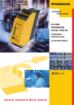
Ultrasonic label and splice sensor
with 1 or 2 switched outputs
■ Assured detection of labels made
of paper, metal or (transparent)
plastic.
■ Detection of splices of paperwebs,
plastic webs or metal webs.
■ Detection of materials with
weights from <20 g/m2 to >>400
g/m2; sheet metals and plastic
films up to 0,2 mm thickness.
■ 3 Teach-in methods + QuickTeach.
■ Parameterisable with LinkControl.
■ Response time of 300 µs until label/splice is detected.
■ Two fork depths of 67 mm and
150 mm.
Safety tips
esf-1/CF
esf-1/CDF
esf-1/15/CDF
Functional principle
An ultrasonic transmitter in the lower
tine of the fork beams a fast sequence of pulses through the backing material. The sound pulses cause
the backing material to vibration, so
that a greatly attenuated sound save
is beamed from the opposite side.
The receiver in the upper tine of the
fork receives and evaluates this
sound wave.
The backing material transmits a different signal level from the level with
label or from a splice. The difference
between the backing material and
backing with label or the web material and splice can be very subtle. To
ensure reliable detection, the esf-1
sensor must therefore initially learn
the signal level for the backing or
web material.
The esf-1 sensor can be used as a label sensor or a splice sensor.
With its three Teach-in methods, the
esf-1 sensor can optimally be adjusted to any task configuration.
With QuickTeach, there is also a simplified Teach-in procedure available.
■ Read instruction manual before
commissioning.
■ Connection, installation and adjustment may only be carried out
by trained technicians.
■ Not a safety component as defined by the EU Machinery Directive.
Installation
Install the esf-1 in such a way that
the tine with the button is on top.
This installation orientation permits you to keep the measuring
track optimally clean.
Connect the connection line with
the 4-pin M8 connector as shown
in Fig 1, and that with the 5-pin
M12 connector as shown in Fig. 2.
2
4
1
3
colour
1
operating voltage +UB
brown
3
4
2
operating voltage -UB
blue
label/splice output F
Teach-In/Com
black
white
Fig. 1:
Pin assignment of esf-1/CF and colour
coding for microsonic connection
lines
2
1
3 5
4
operating voltage +UB
operating voltage -UB
1
3
4
2
5
Fig. 2:
label/splice output F
web break output D
Teach-in/Com
colour
brown
blue
black
white
grey
Pin assignment of esf-1/CDF an
esf-1/15/CDF and colour coding of
Pointer
■ To use QuickTeach, you have to
decide whether the sensor will act
as a label or a splice detector.
■ Once QuickTeach is activated, you
can't switch between NCC/NOC
any more.
■ The QuickTeach functionality is
available for sensors with lot numbers > 12xxxxx.
the microsonic connection lines
Commissioning
Turn the power supply to the esf-1
on.
operation
mode
ready to
operate
backing
material
label/splice
web break
error in
Teach-In
Fig. 3:
Insert the web material into the
fork and carry out one of the three
standard Teach-in methods or
QuickTeach.
LED green LED yellow LED red
on
-
-
on
off
off
on
on
on
off
off
on
on
off
on
LED display
Working
The esf-1 continually performs measurements and sets the switched outputs based on its results.
Parameterisation with LinkControl
The esf-1 can be extensively parameterised with LinkControl. To do this,
you need the optionally available
LCA-2 LinkControl adapter and the
LinkControl software for Windows©.
Use in LinkControl
Install the LinkControl software
onto your PC.
Connect the LinkControl adapter
to your PC using the USB cable.
Connect esf-1 to the LCA-2 as
shown in the table in Fig. 4.
Connect the cable for the power
supply to the LCA-2 on the other
side of the T plug.
Start the LinkControl software and
follow the instructions on the
screen.
Factory setting
The esf-1 sensors have the following
settings configured at the factory:
+UB
-UB
Com
Pin
(esf-1)
1
3
2/5
adapter
cable colour
brown
blue
grey
Pin
(LCA-2)
1
3
5
Teach-in with push-button
and control input
esf-1/CF
■ Label/splice output F on NOC.
■ QuickTeach is deactivated.
The Teach-in process can optionally
be carried out with the button on
the top tine of the fork or with the
Teach-in input on pin 5 on the M12
connector or pin 2 on the M8 connector.
esf-1/CDF and esf-1/15/CDF
■ Label/splice output F on NOC.
■ Output D2 on web break display.
■ Output web break on NOC.
■ QuickTeach is deactivated.
You can change the following settings:
■ NOC/NCC
function
of
the
switched outputs.
■ Switched output function D.
Synchronisation
There is also a graphical representation of the measured values available.
Pointer
■ The Teach-in/Com control input is
parallel with the push-button.
■ +UB connected to the control input correponds to a key press.
Standard Teach-in
There are 3 Teach-in methods available:
■ Dynamic Teach-in of label
■ Separate Teach-in for backing material and labels
■ Splice sensor
If multiple esf-1 sensors are operated
in tight quarters, they can influence
one another. To avoid this, the esf-1
sensors can be synchronised. To do
this, all Teach-in/com control inputs
are connected together (see Figs. 1
and 2 for the connector pinouts).
Pointer
■ A Teach-in using the control input
can also be carried out with synchronisation active.
Fig. 4:
Connection of esf-1 to the LCA-2
Maintenance
The esf-1 is maintenance-free. For
significant deposits of dirt, we recommend carefully blowing out the
measuring track with clean, oil-free
compressed air.
QuickTeach
With QuickTeach, you have a simplified Teach-in process that you have
to activate once before initial commissioning.
2004/108/EG
Standard Teach-in methods
QuickTeach
a)
Further settings (only available in standard Teach-in methods)
b)
Dynamic Teach-in of
label
Static Teach-in of
label
Teach-in only for
sheeting
(splice sensor)
Activate QuickTeach
QuickTeach
label sensor
QuickTeach
splice sensor
Insert the backing
material with label
into the fork.
a) Only insert backing
material into the
fork.
Insert web material
into the fork.
Turn off operating
voltage.
Insert backing material with label into
the fork.
Press push-button1)
for 3 s, until red LED
is off and yellow and
green LED flash
mutually.
Press push-button1)
for 6 s, until red and
yellow LED are off
and green LED
flashes.
Press push-button1)
for 9 s, until red and
green LED are off
and yellow LED
flashes.
LED red: off
LED green: flashes briefly
LED yellow: on
LED red:
LED green:
LED yellow:
LED red: off
LED green: flashes briefly
LED yellow: on
Pull the backing material with label
through the fork at a
constant speed.
Pull some backing
material through the
fork.
Press push-button1)
for 1 s.
Press push-button1)
for 1 s
LED red:
LED green:
LED yellow:
off
flashes briefly
on
Enable/disable Teachin push-button1)
Reset to factory setting
Insert web material
into the fork.
Turn off operating
voltage.
Turn off operating
voltage.
Press push-button1).
Press push-button1)
(LED red: off, LED
green: flashes, LED
yellow: on) and continue to hold it down.
Press push-button1)
(LED red: off, LED
green: flashes, LED
yellow: on) and continue to hold it down.
Press push-button1).
Press push-button1).
Pull web material
(without splice)
through the fork.
Turn on operating
voltage.
Pull the backing material with labels
through the fork at a
constant speed.
Pull web material
(without splice)
through the fork.
Turn on operating
voltage.
Turn on operating
voltage.
Press push-button1)
for 1 s.
Hold down push-button1) for 6 s, until red
and green LED light
up and yellow LED
flashes.
Press push-button1)
for 3 s, until red LED
comes on and green
and yellow LED flash
mutually.
Press push-button1)
for 10 s until red and
yellow LED light up
and green LED
flashes.
Press push-button1)
for 13 s, until red LED
comes on and green
and yellow LED flash
simultaneously.
on
flashes briefly
off
b) Place label on
backing material into
the fork.
Adjusting label/
splice
output F to NCC/NOC
LED yellow: flashes briefly:
QuickTeach
label sensor
or
LED red: flashes briefly:
QuickTeach
splice sensor
oder
LED red: on
LED green: flashes briefly
LED red: on
LED green: flashes briefly
LED yellow on: output F
set for label/
splice
off: output F
not set for label/splice
LED yellow on: push-button disabled
off: push-button enabled
LED green: flashes briefly:
Standard Teach-in method
Press push-button1)
for 1 s
LED red:
LED green:
LED yellow:
To switch modes,
press push-button1).
To switch the
output function,
press push-button1).
To switch function,
press push-button1) .
Do not press pushbutton1) for 10 s.
Do not press pushbutton1) for 10 s.
Release push-button1), before
the operating voltage is turned off.
on
flashes briefly
off
Move the label on
the backing material
in the fork.
Press push-button1)
for 1 s.
Normal operation
Do not press pushbutton1) for 10 s.
Release
push-button1).
Normal operation
Release
push-button1).
Normal operation
1) All settings via push-button can alternatively be made by connecting the Teach-in/control input2004/108/EG
Com to +UB.
Technical data
U
1
2
4
5
3
+UB
D
F
Teach-in/Com
-UB
esf-1/CF
esf-1/CF
esf-1/15/CDF
6 mm
67 mm
500 kHz
web material with grammages of
< 20 g/m2 to >> 400 g/m2, metal-laminated
paper and films up to 0,2 mm thick, selfadhesive films, labels on backing material
20 V to 30 V DC
± 10 %
≤ 50 mA
4-pin M8 initiator plug
Teach-in push-buton, control input Pin 2
Teach-in, LinkControl
300 µs – 2 ms, depending on the material
LED green: working/backing material
LED yellow: label/splice
LED red: web break, Teach-in dismissed
aluminium anodized; plastic parts: PBT, PA;
ultrasonic transducer: polyurethane,
epoxy resin with glass content
IP 65
+5 °C to +60 °C
-40 °C to +85 °C
80 g
EN 60947-5-2
< 300 ms
6 mm
67 mm
500 kHz
web material with grammages of
< 20 g/m2 to >> 400 g/m2, metal-laminated
paper and films up to 0,2 mm thick, selfadhesive films, labels on backing material
20 V to 30 V DC
± 10 %
≤ 50 mA
5-pin M12 initiator plug
Teach-in push-buton, control input Pin 5
Teach-in, LinkControl
300 µs – 2 ms, depending on the material
LED green: working/backing material
LED yellow: label/splice
LED red: web break, Teach-in dismissed
aluminium anodized; plastic parts: PBT, PA;
ultrasonic transducer: polyurethane,
epoxy resin with glass content
IP 65
+5 °C to +60 °C
-40 °C to +85 °C
80 g
EN 60947-5-2
< 300 ms
6 mm
149,5 mm
500 kHz
web material with grammages of
< 20 g/m2 to >> 400 g/m2, metal-laminated
paper and films up to 0,2 mm thick, selfadhesive films, labels on backing material
20 V to 30 V DC
± 10 %
≤ 50 mA
5-pin M12 initiator plug
Teach-in push-buton, control input Pin 5
Teach-in, LinkControl
300 µs – 2 ms, depending on the material
LED green: working/backing material
LED yellow: label/splice
LED red: web break, Teach-in dismissed
aluminium anodized; plastic parts: PBT, PA;
ultrasonic transducer: polyurethane,
epoxy resin with glass content
IP 65
+5 °C to +60 °C
-40 °C to +85 °C
160 g
EN 60947-5-2
< 300 ms
esf-1/CDF
Push-Pull, +UB - 4 V, -UB + 2 V, Imax. = 100 mA,
short circuit proof, switchable NOC/NCC
pnp, +UB - 3 V, Imax. = 100 mA,
short circuit proof,
esf-1/15/CDF
Push-Pull, +UB - 4 V, -UB + 2 V, Imax. = 100 mA,
short circuit proof, switchable NOC/NCC
pnp, +UB - 3 V, Imax. = 100 mA,
short circuit proof,
1 Push-Pull and 1 pnp switched output
1
U
+UB
Teach-in/Com
2
4
3
F
-UB
1 Push-Pull switched output
fork width
fork depth
transducer frequency
working range
operating voltage UB
voltage ripple
no-load current consumption
type of connection
controls
programmable
response time1)
indicator
housing
class of protection to EN 60529
operating temperature
storage temperature
weight
norm conformity
time delay before availibility
order no. esf-1/CF
label/splice output F Push-Pull, +UB - 4 V, -UB + 2 V, Imax. = 100 mA,
short circuit proof, switchable NOC/NCC
web break output D
1)
Can be programmed with Teach-in and LinkControl
*B9766*
MV-DO-129959-437407
microsonic GmbH | Hauert 16 | 44227 Dortmund | Germany | Tel: +49 2 31 / 97 51 51-0 | Fax: +49 2 31 / 97 51 51-51 | E-Mail: [email protected] | www.microsonic.de The content of this document is subject to technical changes. Specifications in this document are presented in a descriptive way only. They do not warrant any product features.