1
Page 2 of 2
Targa by Draper
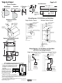
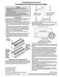
Case Dimensions
Types of Installation
5 1/4"
Suspended
Wall Mounted
Appropriate hardware
provided by installer.
Fabric width + 7"
5
6" Extension 2 /16"
Bracket
5 7/8"
6"
Appropriate hardware
provided by installer.
Methods of Installation
Fasteners for
wall mounting
by others.
7/8" dia.
electrical
connection
hole
Viewing
surface
31/2"
Wiring Diagrams—110-120V Motor and Quiet Motor
Multiple Station Control
Single Station Control
Internal Screen Wiring
White (Common)
Black (Down)
Red (Up)
Green (Ground)
S Hooks for
suspended
installation
by others.
Internal Screen Wiring
White (Common)
Black (Down)
Red (Up)
Green (Ground)
7/8"
hole for
electrical
connection.
Cap off with wire
nut and tape
Dashed wiring
by electrician
Blue
Control
switch
Red
Single gang box by others
Min. 4" x 2 1/8" x 1 7/8" deep
Red
Blue
Black
Red
Optional Ceiling Opening Trim Kit
(Dims-Side View)
Dashed wiring
by electrician
Black
Blue
Location of key
operated on-off
switch if furnished
Black
Blue
Red
To 110-120V Line
Black
Single gang box by others
Min. 4" x 2 1/8" x 1 7/8" deep.
3 shown. More or less equally
feasible.
Location of key
operated on-off
switch if furnished
To 110-120V Line
8"
Wiring Diagrams—110-120V Motor and Quiet Motor
with Built-in Low Voltage Controller
Single Low Voltage Control Multiple Low Voltage Controls
21/16"
Internal Screen Wiring
White (Neutral)
Black
Green (Ground)
11/16"
21/8"
Internal Screen Wiring
White (Neutral)
Black
Green (Ground)
4"
63/4"
Dashed wiring
by electrician
Data Cable
Dashed wiring
by electrician
Data
Cables
POTS
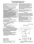
ILT Limit Adjustment Continued from Page 1
➄ To set the viewing surface to an alternate format
To Motor
position, move the viewing surface to the desired
with
position and press the STOP button. Press and
UD
C + Built-In
5V
p o
o
Low Voltage
DC
w
m
hold STOP for at least three seconds to record
n
m
o
n
the position.
FUNCTION
POSITION
Please Note: Pressing and
P
PO
OT
TS
S
Set LOWER limit
DOWN
releasing the UP button on the
Set UPPER limit
UP
switch will move the screen to its
upper limit. Pressing and releas- CENTER Normal Operation
To Motor
ing the DOWN button will move
with
Slide
Built-In
Switch
the screen to its lower limit.
Low Voltage
Back View
While the motor is in motion, pressing STOP for
less than two seconds will stop the viewing surface at its present position.
Once the motor is stopped, pressing the STOP button will move the viewing
surface to its alternate format position.
Pressing and holding the STOP button, when the motor is at rest or in motion,
for at least three seconds will record a new
www.draperinc.com
alternate format position.
Wall Switch,
RF or IR
Receiver,
or integrated
control system
To 110-120V Line
(765) 987-7999
To 110-120V Line
Wall Switches,
RF or IR
Receivers,
or integrated
control systems