1
Installation and maintenance
instructions
Gas wall hung Boiler
condensing
7215 3100-00.1TD
7215 3100 (05/2009) GB/IE
Buderus 500-24C
Buderus 500-28C
For the installer
Please read thoroughly
Contents
Contents
Preface
Regulations and directives
3
Hazard definitions and abbreviations
5
1
1.1
1.2
1.3
1.4
1.5
1.6
1.7
1.8
1.9
1.10
1.11
1.12
Installation
Technical specifications
Dimensions, connections and assembly
Boiler locations and clearances
Items supplied with unit
Hanging the boiler
Install the wall-spacing frame
Water circulation system
Pipe connections
Flue installation
Electrical connections
External controls
System examples
6
6
8
9
10
11
12
13
14
19
25
26
31
2
2.1
Commissioning
Preparing the boiler for operation
34
35
3
3.1
3.2
Inspection
General directions
Preparing the boiler for inspection
46
46
46
4
4.1
4.2
4.3
Maintenance
Cleaning the heat exchanger and burner
Cleaning the condensate trap and syphon
Cleaning or replacing the plate heat exchanger
47
47
50
51
5
5.1
5.2
5.3
5.4
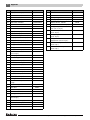
Appendix
Fault codes
Wiring diagram
Residual pump lift
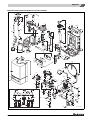
Spare parts list
52
52
53
54
55
Important general instructions
The appliance is designed exclusively for heating water as
part of a domestic central heating and/or hot water system. Do not use the appliance for any other purpose.
Installation, maintenance and repair must be carried out
by a competent engineer (e.g. CORGI registered). Only
use the boiler in conjunction with Buderus accessories
and spares. Other accessories and consumables may be
used if they are expressly provided for the designated use
and if system performance and safety are not affected in
any way.
The boiler is suitable for connection to fully pumped,
central heating systems ONLY.
BENCHMARK' Log Book
All Buderus gas fired boilers include an installation, commissioning and service record log book. The details of the
log book will be required in the event of any warranty work
being requested.
Please complete the appropriate sections on completion
of the installation and commissioning.
REMEMBER: Please leave the log book with the
installed boiler.
Gas Council Aplliance No. :
Buderus 500-24C 47-110-04
Buderus 500-28C 47-110-03
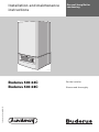
These Installation and maintenance instructions apply to:
Buderus wall-mounted condensing gas combi boilers
models 500-24C and 500-28C.
Flue type:
C13x, C33(x), C53(x), C73(x)
Type:
GB/IE II2H3P 20 mbar; 37 mbar
In this document:
NG = 2H-G20-20 mbar
LPG = 3P-G31-37 mbar
Electrical rating:
230 VAC, 50 Hz, IP X4D
Fuse rating:
2.5 Ampere slow blow silica filled
The boiler type consists of the following components:
– 500
Gas condensing boiler
– 28
Maximum output is 28 kW
– C
Combination boiler (Integrated
domestic hot water supply).
Other manuals available for this boiler are:
– user manual;
– service instructions.
2
Buderus 500-24C/28C - Subject to modifications resulting from technical improvements
Regulations and directives
Regulations and directives
All gas appliances must be installed by a competent person in accordance with the current Gas Safety (Installation and Use) regulations.
Failure to install appliances correctly could lead to prosecution.
The appliance installation must comply with the current:
Gas Safety Regulations,
IEE Regulations,
Building Regulations,
Building Standards (Scotland) (Consolidation),
Building Regulations (Northern Ireland),
local water by-laws,
Health and Safety Document 635 (The Electricity Work
regulations 1989) and any other local requirements.
The relevant British Standards should be followed,
including:
BS7074:1 :
Code of practice for domestic and
hot water supply
BS6891 :
Installation of low pressure gas
pipework up to 28mm (R1)
BS5546 :
Installation of gas hot water supplies for domestic purposes
EN:12828 :
Central heating for domestic
premises
BS5440:1 :
Flues and ventilation for gas appliances of rated heat input not exceeding 70 kW (net): Flues
BS5440:2 :
Flues and ventilation for gas appliances of rated heat input not exceeding 70 kW (net): Air Supply
BS5449 :
Forced circulation of hot water
systems
BS7593 :
Treatment of water in domestic hot
water central heating systems
BS6798 :
Installation of gas fired boilers of
rated input up to 70 kW (net).
Where no specific instruction is given, reference should
be made to the relevant British Standard codes of Practice.
The manufacturer's notes must not be taken, in any way,
as overriding the statutory instrument laws.
The design and construction of the Buderus wallmounted condensing gas combi boiler 500-24C and
500-28C conforms to the basic specifications listed in
the European directive governing gas-fired appliances
90/396/EEC, and with respect to EN 625, EN 483 and
EN 677.
For optimum long term reliable functioning under domestic conditions, the boiler must be inspected and maintained as per these instructions, at least once a year by an
officially recognised service engineer.
The term "domestic conditions" means that the boiler is
used to provide central heating and / or hot water to no
more than one single family dwelling.
Failure to comply with these instructions will invalidate the
appliance warranty.
Timer Frame Buildings
If the boiler is to be fitted in a timber framed building it
should be fitted in accordance with the Institute of Gas
Engineering document IGE/UP and BS 5440:1.
The appliance must only be installed along with Buderus
flue kits, as these are certified for use with the boiler.
Warning: Notes relating to the heating
system water.
Thoroughly flush the system before it is filled
with water. Use only untreated water or water
treatment product such as Sentinel X100 to
fill and top up the system. For more information about Sentinel call 0151 420 9563.
When using water treatment, only products
suitable for use with Buderus heat exchangers are permitted (e.g. Sentinel X100).
Your warranty is at risk if an incorrect water
treatment product is used in conjunction with
this appliance.
For more information, contact Buderus Technical Product Support Department.
It is most important that the correct concentration of the water treatment product is
maintained in accordance with the manufacturer's instructions.
If the boiler is used in an existing system any
unsuitable additives MUST be removed by
thorough cleaning. BS.7593 details the
steps necessary to clean a domestic central
heating system.
Buderus 500-24C/28C - Subject to modifications resulting from technical improvements
3
Regulations and directives
Warning: In hard water areas, treatment to
prevent lime scale may be necessary - however, the use of artificially softened water is
NOT permitted.
Under no circumstances should the boiler be
fired before the system has been thoroughly
flushed.
Do not use artificially softened water.
When using plastic pipes, then they must
contain a polymeric barrier.
It is allowed to use copper for the first 600
mm. See also subsection 1.8: “Pipe connections” in this manual.
Notes related to domestic hot water.
V The domestic hot water service must be in
accordance with BS 5546 and BS 6700.
V The boilers are suitable for connection to
most types of washing machine and dishwasher appliances.
V When connecting to suitable showers, ensure that:
a.The shower is capable of accepting
mains pressures and temperatures
up to 65 °C.
b.The shower is ideally thermostatic or
pressure balancing.
V Where temporary hardness exceeds
150 mg/litre, it is recommended that a
proprietary scale reducing device is fitted
into the boiler cold supply with the requirements of the local water company.
Caution
Provision must be made to accommodate
the expansion of DHW contained within the
appliance, where a back flow prevention device is fitted BS. 67989: §5.4.3.
Safe handling of substances
No asbestos, mercury or CFCs are included in any part of
the boiler and its manufacture.
4
Buderus 500-24C/28C - Subject to modifications resulting from technical improvements
Hazard definitions and abbreviations
Hazard definitions and abbreviations
Hazard definitions
Danger:
Indicates the presence of hazards that will
cause severe personal injury, death or substantial property damage.
Warning:
Indicates the presence of hazards that can
cause severe personal injury, death or substantial property damage.
Caution:
Indicates presence of hazards that can
cause minor personal injury or property damage.
NOTICE:
Indicates special instructions on installation,
operation or maintenance that are important
but not related to personal injury or property
damage.
Abbreviations
AB
= Automatic Bypass
AV
= Air Vent
BCT
= Buderus cylinder thermostat
BDV
= Buderus diverter valve
CB
= Connection Block
CH
= Central Heating
CHF
= Central Heating Flow
CHR
= Central Heating Return
CT
= Cylinder Thermostat
CWDO
= Condensate water drainage outlet
DHW
= Domestic Hot Water
DV
= Diverter Valve
E
= Earth
L
= Live
LSV
= Lock Shield Valve
MCW
= Mains Cold Water
N
= Neutral
JB
= Junction Box / RTH Relay
PL
= Permanent Live
Prog
= Programmer
PRV
= Pressure relief valve (safety valve)
RT
= Room Thermostat
RV
= ModuLink 250 RF Receiver
T
= Timer
TRV
= Thermostatic Radiator Valve
μ
= micro (as μA - micro Amps)
WC
= Wiring Centre
ZV
= Two Port Zone Valve
Buderus 500-24C/28C - Subject to modifications resulting from technical improvements
5
1
Installation
1
Installation
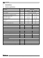
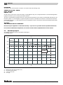
1.1
Technical specifications
Description
Unit
500 Series wall-mounted condensing gas
combi-boiler
500-24C
Type of gas supply as established in
EN 437 (GB/IE)
500-28C
GB/IE II2H3P 20 mbar, 37 mbar
(natural gas H and LPG P)
Rated thermal load for heating
Rated thermal load for preparing hot water
kW
kW
5.7 - 23.0
5.7 - 23.0
5.7 - 23.0
5.7 - 28.5
Rated heating capacity for system temperature
(modulating from 30° to 100°)
Heating curve 75/60 °C
Heating curve 40/30 °C
kW
kW
5.3 - 22.0
6.0 - 24.0
5.3 - 22.0
6.0 - 24.0
Seasonal efficiency (SEDBUK)
for natural gas
for LPG
%
%
90.0
92.3
90.0
92.3
m3/h
m3/h
2.43
2.43
2.43
3.02
Heating water temperature
°C
30 - 80
30 - 80
ΔT at residual head of 200 mbar
°C
< 20
< 20
Max. operating pressure of boiler
bar
3.0
3.0
Pump over run time
min
5
5
l
7.5
7.5
bar
1.0
1.0
l/min
9.4
11.7
Adjustable hot water temperature
°C
40 - 60
40 - 60
Minimum connection pressure
bar
0.8
0.9
Maximum connection pressure
bar
10.0
10.0
Max. gas rate for heating
Max. gas rate preparing hot water
Central heating installation
Expansion vessel
Capacity of expansion vessel
Admission pressure of expansion vessel
Plate heat exchanger
DHW flow rate at 35 °C rise
Pipe connections
Maximum connection pressure
∅ mm
22
CH flow/return (compression fitting)
∅ mm
22
MCW inlet / DHW outlet (compression fitting)
∅ mm
15
Condensate-water outlet
∅ mm
21.5
Pressure relief valve (compression fitting)
∅ mm
15 (adapter supplied with boiler)
6
Buderus 500-24C/28C - Subject to modifications resulting from technical improvements
Installation
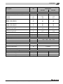
Description
Unit
1
500 Series wall-mounted condensing gas
combi-boiler
500-24C
500-28C
Flue gas values
Condensate water quantity, natural gas, 40/30 °C
l/h
1.6
1.6
Exhaust-fume mass-flow rate
Full load
Part-load
g/s
g/s
10.6
4.3
10.6
4.3
Exhaust-fume temperature, full load
Heating curve 75/60 °C
Heating curve 40/30 °C
°C
°C
77
55
77
55
Exhaust-fume temperature, partial load
Heating curve 75/60 °C
Heating curve 40/30 °C
°C
°C
60
35
60
35
CO2 full load, natural gas
standard test gas G20
%
9.2
9.2
CO2 full load, natural gas
standard test gas LPG
%
10.3
10.3
Standard emission factor CO
mg/kWh
< 22
< 22
Standard emission factor NOx
mg/kWh
< 30
< 30
Flow pressure available for use
Pa
75
75
Flue-gas system
Type of exhaust-fume connection
Diameter of flue take-off
C13(X), C33(X), C53(X), C73(X)
mm
Concentric 60/100
Mains connection voltage (50 Hz)
V
230
Electrical power consumption
Full/Partial load/Standby
W
110/88/4
Electrical data
Electrical protection rating
IP X4D
Boiler dimensions and weight
Height x Width x Depth
mm
780 x 460 x 330
780 x 460 x 330
Weight (without casing)
kg
31
31
Weight (without casing)
kg
3
3
Buderus 500-24C/28C - Subject to modifications resulting from technical improvements
7
1
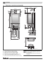
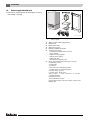
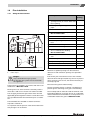
1.2
Installation
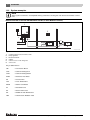
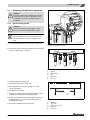
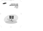
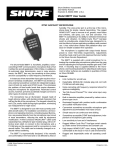
Dimensions, connections and assembly
8 mm
330 mm
460 mm
230 mm
5 mm
21 mm
150 mm
Ø100 mm
5 mm
35 mm
21 mm
780 mm
Ø60 mm
92 mm1
3
5
4
2
6
(3-4) 70 mm
7
(1-2-5) 85 mm
152 mm
(7) 93 mm
157 mm / 162 mm
(6) 108 mm
222 mm
282 mm / 287 mm
352 mm
403.8 mm
328 mm
A
721 mm
376 mm
200 mm
7215 3100-76.1TD
A.
1.
2.
3.
4.
5.
6.
7.
8
outside edge frame
CH flow = Ø 22 mm (compression fitting)
CH return = Ø 22 mm (compression fitting)
DHW outlet = Ø 15 mm (compression fitting)
MCW inlet = Ø 15 mm (compression fitting)
Gas = Gas connection Ø 22 mm (compression fitting)
CDO = Condensate drainage outlet Ø 21.5 mm
PRV = Pressure relief valve Ø 15 mm (compression fitting)
Note
See wall-mounting template for the necessary clearances.
The wall-spacing frame may not always be
necessary.
Buderus 500-24C/28C - Subject to modifications resulting from technical improvements
Installation
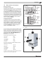
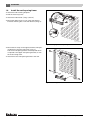
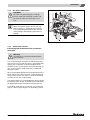
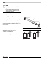
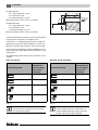
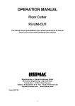
1.3
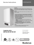
Boiler locations and clearances
600mm
1
600mm
Bathroom Installations
This appliance is rated IP X4D.
750mm
The boiler may be installed in any room or internal space,
although particular attention is drawn to the requirements
of the current IEE (BS.7671) Wiring Regulations and, in
Scotland, the electrical provisions of the building regulations applicable in Scotland, with respect to the installation of the boiler in a room or internal space containing a
bath or shower. If the appliance is to be installed in a room
containing a bath or shower then, providing water jets are
not going to be used for cleaning purposes (as in communal baths/showers), the appliance can be installed in
Zone 3, as detailed in BS.7671.
2
3
2
3
2250mm
600mm
750mm
Compartment Installations
A compartment used to enclose the boiler should be
designed and constructed especially for this purpose. An
existing cupboard or compartment may be used, provided
that it is modified for the purpose. In both cases, details of
essential features of cupboard/ compartment design,
including airing cupboard installation, are to conform to
the following: BS 6798 (No cupboard ventilation is
required - see 'Air Supply' for details).
1
1
1
1
2
3
2250mm
600mm A
Fig. 1
A
7215 3100-01.1TD
Bathroom Installations
= Radius
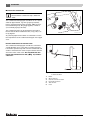
It is not necessary to have a purpose-provided air vent in
the room or internal space in which the boiler is installed.
Neither is it necessary to ventilate a cupboard or compartment in which the boiler is installed, due to the low surface
temperatures of the boiler casing during operation; therefore the requirements of BS 6798, Clause 12, and
BS 5440:2 may be disregarded.
E
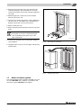
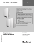
The permanent clearances required are:
A = in front
8 mm
B = below
21 mm
C = right side
5 mm
D = left side
5 mm
E = above
21 mm
The position selected for installation MUST allow adequate space for servicing:
A = in front
350 mm
B = below
180 mm
C = right side
5 mm
D = left side
5 mm
E = above
200 mm
In addition, sufficient space may be required to allow lifting access to the wall-mounting bracket.
D
C
A
B
Fig. 2
7215 3100-02.1TD
Compartment Installations
Buderus 500-24C/28C - Subject to modifications resulting from technical improvements
9
1
1.4
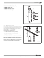
Installation
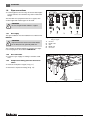
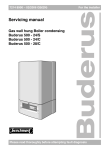
Items supplied with unit
V Check the contents against the packing list to ensure
that nothing is missing.
2
6
7
4
5
1
3
7215 3100-03.1TD
Fig. 3
1:
2:
3:
4:
5:
6:
7:
10
Items supplied with unit
Key to fig. 3:
Wall-mounted condensing gas boiler
Wall bracket
Manifold Assembly
Wall-spacing frame
Bracket for ModuLink 250 RF
Technical documents:
1 x Installation and maintenance manual
1 x User manual
1 x Wall-mounting template
1 x Benchmark Logbook
1 x Warranty card
1 x Envelope for Warranty card
Plastic bag containing the following accessories:
4 x wall fixing screws
4 x wall plugs
4 x washers
4 x push fit rivet for wall-spacing frame
2 x rubber stops for wall-spacing frame
3 x cable clamp - top part
6 x cable clamp - fixing screw
Seals (1 x G½“ - 1“, 2 x ¾“ - 22 mm, 2 x ½“ - 15 mm)
1 x MCW inlet filter
Initial start-up sticker
Second identification plate
Pressure Relief Valve compression fitting + brass insert
Radiator key
Buderus 500-24C/28C - Subject to modifications resulting from technical improvements
Installation
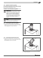
1.5
1
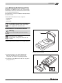
Hanging the boiler
Note
Pipework from the boiler is routed downwards as standard, but may be routed upwards behind the boiler using the wallspacing frame (supplied with the boiler).
If using the supplied wall-spacing frame, follow the procedure in section 1.6.
CAUTION!
DO NOT remove the polystyrene foam bottom slab until lifted into position.
During installation work, cover the condensing boiler and flue connection to prevent site
dirt from entering.
2
1
7215 3100-04.1TD
Fig. 4
Installation
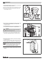
V Attach the wall-mounting template.
V Drill the necessary holes.
V Attach the manifold assembly to the wall (Æ fig. 4,
item 1).
V Make the pipework connections to the manifold.
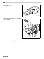
V Attach the wall bracket (Æ fig. 4, item 2).
V Open the locking mechanism using a radiator key
(Æ fig. 5, item 1). The radiator key is included in the
delivery of the boiler in the accessories bag.
V Detach the casing of the condensing gas boiler
(Æ fig. 5).
V Remove the polystyrene foam piece from the top of the
boiler.
V Hang the condensing gas boiler onto the wall bracket
(Æ fig. 4).
7215 3100-05.1TD
Fig. 5
Remove casing
Note
If the boiler isn't connected to the pipework
immediately, place caps on the pipe connections.
V Connect manifold unions to the boiler using supplied
seals.
Buderus 500-24C/28C - Subject to modifications resulting from technical improvements
11
1
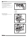
1.6
Installation
Install the wall-spacing frame
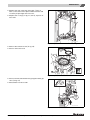
V Attach the wall-mounting template.
V Drill the necessary holes.
V Attach the wall bracket (Æ fig. 4, item 2).
V Mount the rubber stops in one of the wall-spacing
brackets and hang this on the wall bracket (Æ fig. 6).
7215 3100-06.1TD
Fig. 6
Hanging the wall-spacing bracket
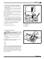
V Mount the two strips on the upper and lower wall-spacing brackets using the snap rivets (Æ fig. 7).
The lower wall-spacing bracket is fitted upside down
compared to the upper wall-spacing bracket, ie. with
the hooks facing down.
V Attach this lower wall-spacing bracket to the wall.
7215 3100-07.1TD
Fig. 7
12
Mounting the lower bracket
Buderus 500-24C/28C - Subject to modifications resulting from technical improvements
Installation
1
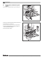
V Mount the lower bracket on the wall and attach the
manifold assembly. If the manifold does not sit flat,
check the orientation of the lower wall-spacing bracket
(Æ fig. 8).
V Make the pipework connections to the manifold.
See also subsection 1.8.
V Open the case locking mechanism, using a radiator key
(Æ fig. 5, item 1). The radiator key is included in the
delivery of the boiler, in the accessory bag.
V Remove the boiler case.
V Remove the polystyrene foam piece from the top of the
boiler.
Note
If the boiler is not to be connected the pipework immediately, then place caps on the
pipe connections.
7215 3100-08.1TD
V Connect the manifold unions to the boiler, using the
seals supplied.
Fig. 8
Mounting the manifold
V Hang the boiler (Æ fig. 9) onto the upper wall-spacing
frame bracket.
7215 3100-09.1TD
Fig. 9
1.7
Hanging the boiler
Water circulation system
The central heating system should be installed in accordance with BS.6798 and, in addition, for smallbore and
microbore systems, BS.5449 or EN 12823.
Buderus 500-24C/28C - Subject to modifications resulting from technical improvements
13
1
1.8
Installation
Pipe connections
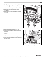
V Connect pipes as shown in fig. 10. Ensure that all pipework is routed so as to minimise any strain on the boiler
fittings.
The first 600 mm of pipework must be in copper, then
another approved material type can be used.
CAUTION!
Do not use galvanised radiators or pipes.
1.8.1 Gas supply
The gas installation must be installed in accordance with
BS.6891.
CAUTION!
Pipework from the meter to the boiler MUST
be of adequate size, generally Ø22 mm.
The complete installation MUST be tested for gas tightness and purged as described in IGE/UP/1b.
1
2
3
4
5
7215 3100-10.1TD
Fig. 10 Pipe connections
Key to fig. 6
1:
2:
3:
4:
5:
CH flow
DHW outlet
Gas
MCW inlet
CH return
1.8.2 Gas connection
V Connect to gas supply according to relevant standards.
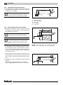
1.8.3
Compression fitting pressure relief valve
outlet
V Insert the small piece of pipe (Æ fig. 11).
V Attach the compression fitting (Æ fig. 12).
7215 3100-11.1TD
Fig. 11 Insert pipe
14
Buderus 500-24C/28C - Subject to modifications resulting from technical improvements
Installation
1.8.4
1
Hot-water temperature
CAUTION!
DO NOT use galvanised pipes or fittings.
The hot water heat exchanger contains copper and can suffer from electrolytic corrosion.
Note
When using plastic pipes, observe the supplier’s instructions - especially those referring
to recommended jointing techniques and the
notes relating to the heating system water on
page 3.
7215 3100-12.1TD
Fig. 12 Compression fitting
1.8.5 Condensate removal
Positioning and termination of the condensate
drain pipe
Warning:
Any external run must be insulated with water
proof insulation.
The condensate pipe should be run and terminate internally to the house soil and vent stack or waste pipe. Alternatively, the condensate can be discharged into the
rainwater system if connected to a foul water draining system, or into a purpose-made soak away (condensate
absorption point).
All connecting drainage pipework should generally have a
fall of at least 2.5° to the horizontal, or approximately 50
mm per metre of pipe run. If this is can not be achieved,
consider the use of a condens pump.
If an external pipe run is unavoidable then the run should
be limited to 3 m in length. Should this be exceeded then
the pipework diameter should be increased to 32 mm.
It should be noted that the connection of a condensate
pipe to a drain may be subject to local building controls.
Buderus 500-24C/28C - Subject to modifications resulting from technical improvements
15
1
Installation
Materials for condensate
Note
Ensure that the condensate trap is filled with
water.
The condensate drainage pipe should be run in a standard drain pipe material, e.g. PVC (polyvinyl-chloride),
PVC-u (unplasticized polyvinyl-chloride), ABS (acrylonitrile-butadienestyrene), PP (polypropylene) or PVC-C
(cross-linked polyvinyl-chloride).
The condensate drain can be attached to the syphon.
Ensure that the black rubberised olive (Æ fig. 13) is correctly aligned.
Any internal pipework should be of a diameter to match
the requirements of the condensate exit pipe on the appliance.
7215 3100-13.1TD
Fig. 13 Condensate outlet
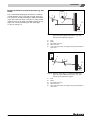
Internal termination to internal stack
The condensate drainage pipe should have a minimum
outside diameter of 21.5 mm with no length restriction.
It should incorporate a trap with a 75 mm condensate seal
and be connected to the stack at a point at least 450 mm
above the invert of the stack. The trap built into the
boiler will provide this 75 mm (Æ fig. 14) condensate seal.
1
3
2
4
5
6
7215 3100-14.1TD
Fig. 14 Internal termination of condensate drainage pipe
to internal stack
1.
2.
3.
4.
5.
6.
16
Boiler
Ø21.5 mm min.
internal soil and vent stack
No length restriction
450 mm min.
invert
Buderus 500-24C/28C - Subject to modifications resulting from technical improvements
Installation
1
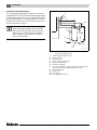
External termination via internal branche (e.g. sink
waste)
2
The condensate drainage pipe should have a minimum
outside diameter of 21.5 mm with no length restriction.
The connection should preferably be made downstream
of the sink waste trap. If the connection is only possible
upstream, then the air break is needed between the two
traps. This can be provided by the sink waste pipe
(Æ fig. 14 and fig. 15).
4
1
3
5
7215 3100-15.1TD
Fig. 15 External termination of condensate drainage
pipe via internal discharge branch (e.g. sink
waste) and condensate syphon
1.
2.
3.
4.
5.
Sink
Boiler
No length restriction
Ø21.5 mm min.
open end of pipe direct into gully, below ground but above
water level
2
4
1
5
3
7215 3100-16.1TD
Fig. 16 External termination of condensate drainage
pipe via internal discharge branch (e.g. sink
waste) and condensate syphon
1.
2.
3.
4.
5.
Sink
Boiler
No length restriction
Ø21.5 mm min.
open end of pipe direct into gully, below ground but above
water level
Buderus 500-24C/28C - Subject to modifications resulting from technical improvements
17
1
Installation
Condensate absorption point
1
The condensate drainage pipe should have a minimum
outside diameter of 21.5 mm and the external pipe length
should not be more than 3 m. The condensate absorption
point should be sited in a convenient position as close as
possible to the boiler but not in the vicinity of other services. For information Æ fig. 17.
2
3
8
Note
When discharging condensate to an outside
drain caution must be taken to ensure blockage cannot occur during freezing conditions.
If this is likely to occur, the use of a syphon
trap is recommended.
4
9 10
5
6
11
7
7215 3100-17.1TD
Fig. 17 External termination of condensate drainage
pipe to absorption point
1.
2.
3.
4.
5.
6.
7.
External length of pipe 3 m max.
Ø21.5 mm min.
Ø1000 mm min.
Ø100 mm min. plastic tube
bottom of tube sealed
limestone chippings
Two rows of three 12 mm holes at 25 mm centres 50 mm
from bottom of tube and facing away from house
8. Ground (either/or)
9. 25 mm min.
10. 300 mm min.
11 hole depth 400 mm min.
18
Buderus 500-24C/28C - Subject to modifications resulting from technical improvements
Installation
1.9
Flue installation
1.9.1
Siting the flue terminal
Terminal position
A
C
Directly below, above or alongside an 300 mm
opening window, air vent or other ventilation opening
B.
Below guttering, drain pipes or soil
pipes
200 mm
C.
Below eaves
200 mm
D.
Below balconies or a car port roof
Not recommended!
200 mm
E.
From vertical drain pipes or soil pipes
150 mm
F.
From internal or external corners
300 mm
G. Above adjacent ground, roof or balcony 300 mm
level
N
B,C
B,C
M
A
F
G
E
K
L
K
F
F
M
G
L
K
1
D
H, I
H.
From a surface facing the terminal
600 mm
I.
From a terminal facing a terminal
1200 mm
J.
From an opening in a car port (e.g.
door or window) into dwelling.
Not recommended!
1200 mm
K.
Vertically from a terminal on the same
wall
1500 mm
L.
Horizontally from a terminal on the wall 300 mm
G
J
F
K
M. Adjacent to opening
300 mm
G
N.
300 mm
Above intersection with roof
O. From a vertical structure on the roof
7215 3100-18.1TD
Fig. 18 Flue terminal position
1
Maximum
Spacing
A.
O
N
1
under carport
Danger:
Only use Buderus flue gas systems.
As other flue gas systems are not tested with
this appliance.
The flue must be installed in accordance with the recommendations of BS.5440-1:2000.
Pluming will occur at the terminal so terminal positions
where this could cause a nuisance should be avoided.
The air supply and the flue gas exhaust must meet the
applicable general regulations. Please consult the instructions provided with the flue terminal kits prior to installation.
500 mm
Tab. 1 Balanced flue terminal position
Minimum acceptable spacing from the terminal to
obstructions and ventilation openings are specified in
table 1.
If the lowest part of the terminal is less than 2 metres
above the level of the ground, balcony, flat roof or place to
which any person has access, the terminal must be protected by a guard.
Ensure that the guard is fitted centrally.
The flue assembly shall be so placed or shielded as to
prevent ignition or damage to any part of the building.
The air inlet/products outlet duct and the terminal of the
boiler MUST NOT be closer than 25 mm to combustible
material. Detailed recommendations on the protection of
combustible material are given in BS.5440-1:2000.
The boiler MUST be installed so that the terminal is
exposed to external air.
It is important that the position of the terminal allows the
free passage of air at all times.
Buderus 500-24C/28C - Subject to modifications resulting from technical improvements
19
1
Installation
NOTE
It is absolutely essential to ensure, in practice, that products of combustion discharging from the terminal cannot re-enter the
building or any other adjacent building
through ventilators, windows, doors, other
sources of natural air infiltration, or forced
ventilation/air-conditioning.
If this could occur the appliance MUST be turned off (with
the owners permission), and labelled as unsafe until corrective action can be taken.
1.9.2
Air supply and flue gas exhaust in a closed
installation
The boiler case incorporates the seal for the air supply
system. It is important that the case is fitted correctly.
1
2
To ensure optimal operation, the 500 Series appliances
must be connected to a Buderus horizontal or vertical flue
terminal. These terminals have been developed specifically for Buderus condensing gas boilers and have been
comprehensively tested for trouble free operation when
correctly installed.
3
7215 3100-19.1TD
Fig. 19 Standard horizontal flue pack
Standard horizontal flue pack (Æ fig 19):
– item 1: Flue turret 60/100;
L
– item 2: Horizontal flue terminal 60/100;
415 mm
– item 3: Flue finishing kit.
5 mm
7215 3100-20.1TD
Fig. 20 Side flue and rear flue installation
20
Buderus 500-24C/28C - Subject to modifications resulting from technical improvements
Installation
1
Standard vertical flue pack (Æ fig. 21):
– item 1: Vertical flue terminal 60/100;
– item 2: Weather collar;
– item 3: Flue support bracket;
– item 3: Vertical flue adaptor.
2
1
3
4
7215 3100-21.1TD
Fig. 21 Standard vertical flue pack
1.9.3 Maximum Flue length
A standard flue comprises a 90 degree takeoff bend and
the horizontal flue outlet or straight takeoff and the vertical
flue outlet. The flue can be extended upto a maximum
effective length (L, Æ fig. 22 and 23).
The maximum effective flue length is:
– 12 metres for the 60/100 flue (Æ table 2)
– 35 metres for the 80/125 flue (Æ table 3)
(see also fig. 22 and 23).
L
When you have determined the length L for the flue system, add up all the bends and extensions used.
Refer to the appropriate table for the effective lengths of
each bend or extension.
The total of the bends and extensions must not add up to
more than the reduction lenghts of the flue length L.
7215 3100-22.1TD
Fig. 22 Vertical flue length
Buderus 500-24C/28C - Subject to modifications resulting from technical improvements
21
1
Installation
Example 60/100:
L
2 x 1 metre extension = 2.0 m
2 x 90° bend = 2.8 m
Total effective length = 4.8 m.
Maximum allowed is 12 m. So this is allowed.
Example 80/1250:
2 x 1 metre extension = 2.0 m
2 x 90° bend = 3.2 m
Total effective length = 5.2 m.
A
7215 3100-23.1TD
Maximum allowed is 35 m. So this is allowed.
Fig. 23 Horizontal flue length
Take the flue terminal clearances into account when planning the layout of the place of installation (see
subsection 1.9.1: "Siting the flue terminal" on page 19).
Maximum wall thickness without extensions is 415 mm.
Maintain a minimum side clearance of 5 mm (Æ fig. 20).
Ensure the flue is adequately supported. Buderus recommend securing each flue extension with a minimum of one
wall bracket.
The additional flue parts listed can be ordered from your
supplier.
Flue size 60/100:
60/100 flue system
Flue size 80/125 (optional):
For every bend or
extension the
max. flue length
(L) has to be
reduced by:
500 mm extension
0.5 m
500 mm extension
0.5 m
1000 mm extension
1.0 m
1000 mm extension
1.0 m
90° bend
1.4 m
90° bend
1.6 m
45° bend
0.7 m
45° bend
0.9 m
Tab. 2
Tab. 3
NOTE
The total reduction length must never exceed
the maximum flue length.
22
80/125 flue system
For every bend
or extension the
max. flue length
(L) has to be
reduced by:
NOTE
Vertical adaptor (60/100 --> 80/125) is required for 80/125 flue gas systems, because
the flue outlet of the boiler is 60/100.
Buderus 500-24C/28C - Subject to modifications resulting from technical improvements
Installation
1
1.9.4 Standard 100 mm flue systems
The standard concentric flue system provides for a maximum horizontal straight length of upto 12.0 m for 60/100
flue connection (see subsection 1.9.3).
Full instructions for fitting this flue are in subsection 1.9.7:
"Installation of the horizontal flue" on page 24.
IMPORTANT
Any horizontal flue system fitted to a condensing boiler must be inclined towards the appliance at an incline of 50 mm per metre
length to prevent condensate dripping from
the flue terminal. This means that the clearance above the appliance must be increased
to match the duct length. See figure on
page 8.
NOTE
Take into account the extra depth of the boiler when using the wall-spacing frame.
1.9.5 Connecting the vertical flue adaptor
V Push the vertical flue adaptor (Æ fig. 23) onto the
appliance flue connector. Ensure that the flue adapter
is fully engaged into the top of the boiler.
7215 3100-24.1TD
Fig. 24 Vertical flue adaptor
1.9.6 Connecting the horizontal flue turret
V Push the horizontal flue turret (Æ fig. 23) onto the
appliance flue connector. Ensure that the flue turret is
fully engaged into the top of the boiler.
1
7215 3100-25.1TD
Fig. 25 Horizontal flue turret with flue gas testing point
1
Flue gas testing point
Buderus 500-24C/28C - Subject to modifications resulting from technical improvements
23
1
Installation
1.9.7 Installation of the horizontal flue
V The standard flue is suitable for lengths upto 660 mm
(Æ fig. 26). For longer flue runs upto 12.0 m, extension
air/flue ducts are available.
2
1
NOTE
Use the wall-mounting template to help you
mark the position of the side flue opening.
4
3
5
7215 3100-26.1TD
Fig. 26 Installation with horizontal flue gas turret
1.
2.
3.
4.
5.
Maximum length
Terminal assembly
Flue turret
Finishing kit
Outer wall
1.9.8 Flue duct preparation and assembly
V Measure the flue length L. Refer to figures 27 and 28.
The length L is from the centre line of the flue turret to
the outside face of the wall.
L
NOTE
The flue must be inclined from the boiler.
A
NOTE
An inner flue finishing kit is provided which
should be fitted to the ducts before assembly.
V When just the terminal assembly is to be used, measure the length L from the raise ring back (Æ fig. 29).
The overall measurement for the outer duct is L minus
70 mm. The overall measurement for the inner duct is
L minus 50 mm. Ensure that the cuts are made square
and a free from burrs.
7215 3100-27.1TD
Fig. 27 Flue length - rear
item A = 150 mm without the use of a wall-spacing frame
item A = 185 mm with the use of a wall-spacing frame
V If the final flue piece is an extension, measure from the
formed end, back. As before the final measurement are
minus 70 mm for the outer and minus 50 mm for the
inner.
L
V Assemble flue system completely. Push the ducts fully
together.
The assembly will be made easier if a solvent free
grease is lightly applied to the male end of the ducts.
7215 3100-28.1TD
Fig. 28 Flue length - side
24
Buderus 500-24C/28C - Subject to modifications resulting from technical improvements
1
Installation
V Push the assembly through the wall and slide the turret
onto the flue connector. Refer to figure 25. Ensure that
the turret is fully engaged into the socket on the boiler.
V From the outside fix the flue finishing kit to the terminal
and, after ensuring the duct is properly inclined
towards the boiler, fix the finishing kit to the wall.
If the terminal is within 2 m of the ground where there
is access then an approved terminal guard must be fitted.
The guard must give a clearance of at least 50 mm
around the terminal and be fixed with corrosion resistant screws.
1
2
3
4
7215 3100-29.1TD
Fig. 29 Flue terminal position
1.
2.
3.
4.
Flue Finishing Kit
Flue Terminal
Outer Wall Face
Raised Ring locating the terminal relative to the outside
wall face
1.10 Electrical connections
Mains connection to the appliance
Warning: Boiler damage!
V Connect the supply cable supplied with
the the boiler to the 230 Volt mains.
V DO NOT connect 230 Volts mains supply
to any other point on the boiler.
ON
OFF
Caution: Electric shock!
Electrically isolate the appliance at the fused
spur before removing the case (Æ fig. 30).
NOTE
All Buderus boilers require a permanent
mains supply of 230 Volts at 50 Hz.
1
7215 3100-30.1TD
Wiring to the boiler MUST be in accordance with the current I.E.E. (BS.7671) Wiring Regulations and any local
regulations. Wiring should be a 3 core PVC insulated
cable, not less than 0.75 mm2 (24 x 0.2 mm), and to
table 16 of BS.6500.
The mains supply to the appliance, and any system controls (thermostat, timer), must be from a dedicated fused
spur.
The spur must be capable of being isolated by either a
double pole switch, having 3 mm contact separation on
both poles, or by a three pin plug and socket arrangement.
Fig. 30 DBA
Damaged mains supply cables must be replaced using
cable as described above, and fitted by a qualified electrician.
The means of isolation must be accessible to the user
after installation (fig. 30, item 1).
The electrical connection to the mains supply should be
readily accessible and adjacent to the boiler.
Buderus 500-24C/28C - Subject to modifications resulting from technical improvements
25
1
Installation
Electrical wiring
Caution:
THIS APPLIANCE MUST BE EARTHED
Ensure that your appliance is connected correctly. If you are in any doubt consult a qualified electrician.
ON
NOTE
The wires in this mains lead are coloured in
accordance with the following code:
EARTH
- GREEN AND YELLOW
NEUTRAL - BLUE
LIVE
- BROWN
The appliance mains cable, wire colours may
not correspond with the markings that identify the terminals on the fuse spur connector,
refer to the guide below:
V Connect green and yellow wire to terminal
marked E or
or coloured green or
green-and-yellow
1
7215 3100-31.1TD
Fig. 31 Electrical wiring
1
Permanent live
V Connect brown wire to terminal marked L
or coloured red
V Connect blue wire to terminal marked N or
coloured black
1.11 External controls
Buderus boilers are designed to modulate based on room
temperature, this reduces the amount of energy used to
heat the property, when compared with using 230V or volt
free controls.
Buderus recommend thermostats from the ModuLink and
RC series in order that the customer can benefit from the
increased comfort and savings of modulating on room
temperature.
The wall-mounted condensing gas combi boiler can be fitted with the following external controls:
1. ModuLink 250 RF (Æ subsection 1.11.1) or other recommended Buderus 24V controls.
2. Room-temperature control device and timer at 230V
connected under the grey cover
(Æ subsection 1.11.2).
3. ON/OFF temperature controller, volt free
(Æ subsection 1.11.3).
Connecting any external controls will require the case
removal to gain access to the boiler control unit (DBA)
1
2
7215 3100-32.1TD
Fig. 32 Lower the DBA
Gain access to the DBA connection block
V Remove the boiler's case (Æ fig. 5 on page 11).
V Remove the securing screw (Æ fig. 32, item 1).
V Lower the boiler control unit (DBA) (Æ fig. 32, item 2).
26
Buderus 500-24C/28C - Subject to modifications resulting from technical improvements
Installation
1
1.11.1 Modulink 250 RF thermostat connection
The ModuLink 250 RF thermostat modulates on room
temperature. The Buderus boilers work most efficiently
with Buderus thermostats. Therefore these thermostats
are recommended by Buderus.
See subsection 1.12 for an installation example with the
ModuLink 250 RF.
The ModuLink 250 RF thermostat comprises:
– wall bracket;
– receiver;
– thermostat.
For installation and operation of the Buderus
thermostat/programmer, refer to the instructions supplied with that thermostat.
ModuLink Receiver and bracket installation
Warning:
Do not connect 230 V AC to the receiver.
1
The receiver is not waterproof.
Prevent water coming into contact with the
receiver.
V Remove the receiver terminal cover (Æ fig. 33, item 1).
7215 3100-33.1TD
Fig. 33 Receiver bracket
V Connect the grey 2 core cable (supplied with
ModuLink 250 RF thermostat) to the receiver
(Æ fig. 34). The wires are not polarity sensitive.
V To refit the cover, slide back on and click into place
(Æ fig. 34, item 1).
1
230V
7215 3100-34.1TD
Fig. 34 Connect cable
Buderus 500-24C/28C - Subject to modifications resulting from technical improvements
27
1
Installation
V Slide the receiver securely into the bracket, supplied
with the boiler (Æ fig. 35).
7215 3100-35.1TD
Fig. 35 Place receiver into bracket
V Slide the bracket in the guide rails on the underside of
the boiler (Æ fig. 36).
7215 3100-36.1TD
Fig. 36 Hang bracket under boiler
V Remove the securing screw (Æ fig. 32, item 1) and
lower the Boiler Control Unit (DBA) (Æ fig. 32, item 2).
28
Buderus 500-24C/28C - Subject to modifications resulting from technical improvements
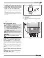
Installation
V Connect the two wires of cable from the ModuLink
receiver to terminal 1 and 2 of the connection block on
the back of the DBA (Æ fig. 37). The wires are not
polarity sensitive.
A green LED will light on the receiver, when installed
correctly and the boiler is reconnected to the mains
electricity supply.
1
1
2
3
4
5
6
7
There is no requirement to setup the RF link between the
thermostat and receiver. This has been completed as part
of the manufacturing process.
The room thermostat sends a signal to the receiver at
least every 30 minutes to see if they are still in contact
with each other.
V If you want to test whether you have reception then
press the
button on the thermostat for more than
5 seconds. The thermostat will now send out a signal
continuously (The LED on the receiver flashes green
and the thermostat shows connecting in the display).
V The receiver will stay in this test mode until the
button on the thermostat is pressed.
V Raise and secure the DBA.
V Refit the boiler casing if necessary.
7215 3100-37.1TD
Fig. 37 Room thermostat connection on DBA
1, 2
3
5
6, 7
Room Thermostat
HW Tank Sensor
24 VAC
3-Way Valve
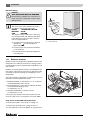
1.11.2 External 230 V controls
Caution:
This appliance must be earthed.
V Remove the securing screw and lower the DBA
(Æ fig. 32).
V Using a screwdriver, remove the grey 230V cover
(Æ fig. 38, item 1).
The grey 230V cover houses one fused circuit board.
The board has four terminals (Æ fig. 39):
–
–
–
–
LOUT
LRTN
NOUT
SPARE
7215 3100-38.1TD
Fig. 38 Room thermostat connection on DBA
LOUT & NOUT are optional LIVE & NEUTRAL supplies from
the boiler which are isolated via the on/off power switch
on the front of the DBA. If required, these can be used to
power a third party 230V thermostat / programmer etc.
Alternatively 230V controls can be powered from a separate mains supply external to the boiler (i.e. LOUT & NOUT
terminals are not used).
Buderus 500-24C/28C - Subject to modifications resulting from technical improvements
29
1
Installation
Using a separate supply is not recommended as the third
party controls will not be isolated by the power switch on
the front of the DBA, although in some replacement installations this may be unavoidable.
1 2 3 4
The direct external mains supply to third party
230V controls must be from the same fused
spur that supplies the boiler, described in
subsection 1.10.
LRTN must be connected with the live return / switched
live signal from the third party 230V controls.
SPARE is a terminal not connected to the circuit board and
can be used as a connection point.
There are two strain relief clamps. The clamps are supplied in the accessory bag, on top of the boiler.
The underside of the grey 230V cover contains a holder
for a spare fuse. Only 2.5 Ampere slow-blow silica filled
fuses should be used.
V Tighten the strain relief clamps to secure the cables.
V Replace the grey 230V cover.
7215 3100-39.1TD
Fig. 39 Connection box - 230 Volt connection
1
2
3
4
NOUT
LOUT
LRTN
SPARE
V Raise and secure the Boiler Control Unit (DBA).
V Refit the boiler casing if necessary (Æ fig. 5).
1.11.3 Volt free external control device connection
V Remove the securing screw of the DBA and lower the
DBA (Æ fig. 32).
V Connect the wire to terminal 1 and 2 of the connection
block, marked Room Thermostat (Æ fig. 37).
30
Buderus 500-24C/28C - Subject to modifications resulting from technical improvements
1
Installation
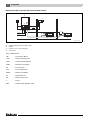
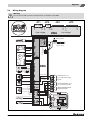
1.12 System examples
NOTE
These system schematics are simplified heating schematics showing the main electrical and water connections.
Buderus 500-24C or 500-28C with ModuLink 250 RF (or other Buderus controls)
1
2
CB
PL
3
JB
RV
CHF
CHR
DHW
TRV
LSV
4
MCW
LSV
4
LSV
5
6
7215 3100-40.1TD
Fig. 40
1
2
3
4
5
6
Condensing gas boiler 500-24C / 28C
RT/programmer
ModuLink 250 RF
radiator
reference room / main living area
other rooms
Key to abbreviations:
CB
= Connection Block
CHF
= Central Heating Flow
CHR
= Central Heating Return
DHW
= Domestic Hot Water
JB
= Junction Box
LSV
= Lock Shield Valve
MCW
= Mains Cold Water
PL
= Permanent Live
RT
= Room Thermostat
RV
= ModuLink 250 RF Receiver
TRV
= Thermostatic Radiator Valve
31
Buderus 500-24C/28C - Subject to modifications resulting from technical improvements
1
Installation
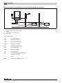
Buderus 500-24C or 500-28C with external 230V controls
1
RT
PL
CB
JB
T
CHF
CHR
DHW
TRV
LSV
2
2
radiator
MCW
LSV
radiator
LSV
3
4
7215 3100-41.1TD
Fig. 41
1
2
3
4
Condensing gas boiler 500-24C / 28C
radiator
reference room / main living area
other rooms
Key to abbreviations:
CB
= Connection Block
CHF
= Central Heating Flow
CHR
= Central Heating Return
DHW
= Domestic Hot Water
JB
= Junction Box
LSV
= Lock Shield Valve
MCW
= Mains Cold Water
PL
= Permanent Live
RT
= Room Thermostat
T
= Timer
TRV
= Thermostatic Radiator Valve
32
Buderus 500-24C/28C - Subject to modifications resulting from technical improvements
1
Installation
Buderus 500-24C or 500-28C with external Volt Programmable Room thermostat
1
PRT
CB
PL
JB
CHF
CHR
DHW
TRV
LSV
2
MCW
LSV
2
LSV
3
4
7215 3100-42.1TD
Fig. 42
1
2
3
4
Condensing gas boiler 500-24C / 28C
radiator
reference room / main living area
other rooms
Key to abbreviations:
CB
= Connection Block
CHF
= Central Heating Flow
CHR
= Central Heating Return
DHW
= Domestic Hot Water
JB
= Junction Box/RTh Relay
LSV
= Lock Shield Valve
MCW
= Mains Cold Water
PL
= Permanent Live
PRT
= Programmable Room Thermostat
(Volt Free Contacts)
T
= Timer
TRV
= Thermostatic Radiator Valve
33
Buderus 500-24C/28C - Subject to modifications resulting from technical improvements
2
2
Commissioning
Commissioning
When a boiler starts up there are a couple of things that
happen. Below is a short process description:
When there is a heat demand:
The fan starts up and the glow ignitor turns on.
When there is a DHW request then the three-way-valve
switches from CH operation to DHW operation.
The pump starts up as soon as the three-way-valve is in
the right position.
Once all the requirements are met (glow ignitor is hot
enough, fan is operating at the correct speed and the
pump is on) then the gas valve will open.
A flame may or may not develop, but regardless of that
fact, the glow ignitor extinguishes. The operating controls
are released once a flame is sensed. After a possible
check, the boiler will deliver the requested output.
Should the flow check fail, the boiler will shut down for a
short while and then try to start up again.
If no flame develops then the gas valve closes and the fan
continues to run for a while to purge the appliance. The
boiler will try to start up three times. If no flame develops
after three attempts the boiler will lock-out.
When the heat demand stops:
The gas valve closes.
The fan will run for a short time to purge the appliance.
The pump will continue to run for a short time to disperse
any remaining heat energy from the boiler into the heating
system.
If there has been a heat request, then the three-way-valve
will switch back to the central heating setting.
Follow the steps described in this chapter to properly
commission the boiler and fill out the commissioning log
book.
NOTE
If a fault occurs, then refer to the servicing
manual or contact Buderus.
34
Buderus 500-24C/28C - Subject to modifications resulting from technical improvements
Commissioning
2.1
Preparing the boiler for operation
Caution:
DO NOT operate the condensing gas boiler
if large amounts of dust are present, e.g. due
to building work in and around the place of
installation.
2.1.1
2
1
Fill the heating system
Caution:
The wall-mounted condensing gas combi
boiler must not be activated at this stage.
NOTE
Please read the notes on heating system water and domestic hot water on page 3 carefully.
7215 3100-43.1TD
V Loosen the automated air vent one turn (Æ fig. 43).
Fig. 43 Automatic air vent
V If necessary open the CH flow and CH return servicing
valves (Æ fig. 44, item 1 and 2).
4
2
5
3
1
7215 3100-44.1TD
Fig. 44 Servicing shut off valves
1
2
3
4
5
CH flow
DHW outlet
Gas
MCW inlet
CH return
V Connect filling loop (Æ fig. 45).
V Open both stop valves (Æ fig. 45).
V Fill the system to a pressure of approx. 1.5 bar
(Æ fig. 44, item 3).
2
V Close both stop valves.
3
V Vent the air from all radiators starting with the lowest
radiator and working up to the highest point.
V Check the pressure after venting. If the pressure has
dropped under 1.0 bar then top up the system as
described previously.
V Disconnect the filling loop and cap off.
2
1
4
5
7215 3100 -45.1TD
Fig. 45 Connecting filling loop
1
2
3
4
5
MCW inlet
stop valve
double check valve
filling loop
CH return
Buderus 500-24C/28C - Subject to modifications resulting from technical improvements
35
2
Commissioning
To drain the boiler take the following steps:
V Close the MCW inlet and the CH return valve.
V Connect drainage hose (Æ fig. 46).
V Close the CH return and CH flow valves.
6
1
1
V Connect draining hose to draining point on the manifold (Æ fig. 46, item 1).
3
V Open draining point to drain the boiler (Æ fig. 46,
item 1).
2
Drain
5
4
7215 3100-46.1TD
Fig. 46 Draining the boiler
1
2
3
4
5
6
stop valve
CH flow
MCW inlet
CH return
drain
drainage hose
Fill the condensate trap
V Remove the condensate trap and fill with water
(Æ fig. 47 and fig. 48).
7215 3100-47.1TD
Fig. 47 Disconnect hose from condensate trap
7215 3100-48.1TD
Fig. 48 Remove the condensate trap and fill with water
36
Buderus 500-24C/28C - Subject to modifications resulting from technical improvements
Commissioning
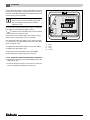
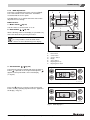
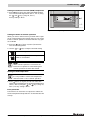
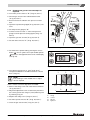
2.1.2 DBA adjustments
The boiler is equipped with a boiler control unit (DBA).
This is the internal control of the boiler. The DBA is
located behind the access panel.
3
4
5
2
6
The DBA allows you to operate the boiler and to make
adjustments in its settings.
DBA overview:
1. Mains switch (Æ fig. 49)
Use this switch to turn the boiler on or off.
2. Reset button
2
(Æ fig. 49)
1
7
When a blinking code is in the display, it is possible to try
and restart the boiler by pressing this button.
NOTE
It is not possible to reset the boiler when
there is no fault code blinking in the display.
7215 3100-49.1TD
Fig. 49 DBA
1
2
3
4
5
6
7
3. Service button
mains switch
“reset” button
“service” button
display
“menu” button
adjusting arrow up
adjusting arrow down
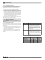
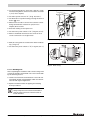
(Æ fig. 49)
The boiler will operate on partial load when the Service
button
is pressed once. An open-ended spanner
appears in the top left hand corner of the display
(Æ fig. 50).
7215 3100-50.1TD
Fig. 50 DBA with open-ended spanner
Press the
button if you want to make sure that the
boiler is actually operating at partial load ('Lo' appears in
the display, Æ fig. 51).
7215 3100-51.1TD
Fig. 51 DBA display Lo
Buderus 500-24C/28C - Subject to modifications resulting from technical improvements
37
2
Commissioning
The boiler operates at full load when the Service button
is pressed again. An open-end spanner
appears
in the top left hand corner of the display.
Press the
button if you want to make sure that the
boiler is actually operating at full load ('Hi' appears in the
display, Æ fig. 52).
The boiler returns to regular operation when the Service
button
is pressed once again or after the boiler has
operated at partial- or full load for 30 minutes.
7215 3100-52.1TD
Fig. 52 DBA display Hi
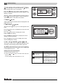
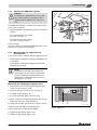
4. Display (Æ fig. 49)
Setting, adjustments and fault codes are displayed on the
DBA (see fig. 53).
5. Menu button
The menu button
items.
(Æ fig. 49)
allows you to scroll through the menu
Press the button once, to display the current warm start
function setting.
Press the button twice to display the current
DHW temperature setting.
Press the button three times to display the current
setting of summer operation.
Press the button four times to display the current
CH flow temperature setting.
6. and 7. Up
and Down
7215 3100-53.1TD
Fig. 53 DBA display
keys (Æ fig. 49)
These keys can be used for adjusting temperatures and
activating or de-activating certain summer operation.
The
key, when pressed, gives the current operating
status of the boiler. Press the
key once to display the
current DHW flow in l/m.
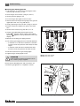
Setting the warm start function
V Press the menu button once.
V Use the
and
keys to turn the warm start function on or off.
Factory setting: warm start function is "on".
Setting
Meaning
- ECO /
cold start
More energy efficient, less
chance of calcification, longer
waiting periods.
- comfort /
warm start
Maximum comfort due to short
waiting period for warm water.
Not as energy efficient as the
cold start and there is more
chance of calcification.
Tab. 4 Warm start function
38
Buderus 500-24C/28C - Subject to modifications resulting from technical improvements
Commissioning
Setting the domestic hot water (DHW) temperature
V Press button twice then adjust the DHW temperature to the desired temperature (40 °C - 60 °C) using
the
and
keys (Æ fig. 54, item 1).
Factory setting is 48 °C.
2
1
2
7215 3100-54.1TD
Fig. 54 DBA – adjusting arrows
Setting the boiler to summer operation
When you want to make sure that your boiler will not operate for central heating in the summer then you can set the
boiler to summer operation. The boiler will then only operate for DHW.
V Press the button (Æ fig. 54, item 2) three times.
The current setting blinks.
V Use the
or
keys to adjust to desired setting.
Central heating is on.
Central heating is off (summer operation).
DHW is still available.
NOTE
When summer operation is active then the
boiler will not operate for central heating until
summer operation has been deactivated.
Setting the flow temperature
NOTE
It is not possible to set the flow temperature
when the boiler is set to summer operation.
V Press button (Æ fig. 54, item 2) four times then
adjust the flow temperature to the desired temperature
(30 °C – 80 °C) using the
and
keys (Æ fig. 49,
item 1). Factory setting is 80 °C.
Frost protection
The boiler has an automatic frost protection. When the
CH flow temperature drops below 7 °C then the boiler will
start up.
Buderus 500-24C/28C - Subject to modifications resulting from technical improvements
39
2
Commissioning
2.1.3 Checking for gas leaks
Use a suitable pressure gauge for the different pressure
readings. It should be able to handle pressures up to
50 mbar with an accuracy of 0.01 mbar minimum.
V Disconnect the system from the power supply.
V Check all sections of gas pipework and connections
for signs of leaks before starting up the system for the
first time. If a leak is detected during tightness testing,
use an approved leak detector to check all connections
for possible escapes. The product must be certified as
a gas leak-testing agent. DO NOT allow the product to
come into contact with electrical wiring.
The test pressure of the gas pipe when the gas shut off
valve is open may not exceed 150 mbar.
Warning: ATTENTION
Check the used measuring nipples for gas
tightness.
2.1.4 Checking the gas type
Ensure that the boiler is set up to run on the gas type available. If this is not the case, then the boiler must not be put
into operation.
Type of gas
Factory settings of gas burners
Natural gas
H
When delivered ready for operation and
set to Wobbe index 14.1 kWh/m3
(referred to 15 °C, 1013 mbar), applicable for Wobbe index range 11.3 to
15.2 kWh/m3. Inscription on gas-type
indicating label:
Category setting: 2H G 20_20 mbar
LPG
After adaptation by a CORGI registered installer, the unit can be run on
LPG. Inscription on gas-type indicating
label:
Category setting: 3P G 31_37 mbar
V Check the gas type with your gas supplier and compare this to the boiler's gas type as registered on the
identfication tag (Æ table 6).
It is possible to change the boiler to another gas type
(Æ table 5). This accessory can be ordered from your
supplier.
Tab. 5 Gas-supply types
Type of gas
Gas injectors ∅
[mm]
Venturi
Buderus 500
24C
28C
tubes
Natural gas H (G20)
4.45
4.45
Standard
LPG
3.45
3.45
Standard
Tab. 6 Gas injector diameter
40
Buderus 500-24C/28C - Subject to modifications resulting from technical improvements
Commissioning
2.1.5
2
Adjusting the DHW flow regulator
Caution:
It is important to adjust the flow of hot water,
due to the resistance of the pipes in the installation and the differences in water pressure.
The DHW flow regulator is located on the bottom frame
of the boiler (Æ fig. 55).
V Adjust the DHW flow regulator (fig. 55) to the desired
setting:
– To increase the flow of hot water:
turn valve clockwise “+”.
– To reduce the flow of hot water:
turn valve counterclockwise “-”.
Factory setting:
10 l/min of 48 °C, assuming that the DHW cold is 10 °C
and there is a pre-pressure of 2.5 bar.
7215 3100-55.1TD
Fig. 55 DHW flow regulator
2.1.6
Measuring the gas-supply pressure
(flow pressure)
There are two ways to measure the gas-supply pressure:
– measuring the standing gas-supply pressure (boiler not
in operation);
– measuring the working gas-supply pressure (boiler
operating at full power).
NOTE
The difference between the standing and
working pressure may never be greater than
5 mbar. If the difference between the two is
greater than 5 mbar then the pressure loss in
the gas pipe is too great.
Measuring the standing gas-supply pressure
V Take the boiler out of service by pressing the mains
switch (Æ fig. 56, item 1) to "0".
V Close the gas shut off valve (Æ fig. 57, item 1).
V Set the pressure gauge to "0".
V Loosen the gas test nipple screw two turns.
V Attach a tube from the pressure gauge to the gas test
nipple (the lower one, Æ fig. 58, item 2).
V Slowly open the gas shut off valve (Æ fig. 57, item 2).
V Measure the standing gas-supply pressure.
1
2
7215 3100-56.1TD
Fig. 56 DBA front
V Pull off the tube from the gas test nipple.
V Tighten the gas testing nipple screw.
V Tighten the gas testing nipple screw.
Buderus 500-24C/28C - Subject to modifications resulting from technical improvements
41
2
Commissioning
Measuring the working pressure
V Take the boiler out of service by pressing the mains
switch (Æ fig. 56, item 1) to "0".
V Close the gas shut off valve (Æ fig. 57, item 1).
V Set the pressure gauge to "0".
V Loosen the gas test nipple screw two turns.
V Attach a tube from the pressure gauge to the gas test
nipple (the lower one, Æ fig. 58, item 2).
V Slowly open the gas shut off valve (Æ fig. 57, item 2).
V Ensure at least two radiators are open to hot water
flow.
V Set the mains switch (Æ fig. 56, item 1) to "1".
V Create a heat demand by pressing the service
button
(Æ fig. 56, item 2), until an open-ended
spanner
appears in the top left hand corner of the
display.
V Measure the working gas-supply pressure.
V The working gas-supply pressure should be between:
– a minimum of 17 mbar and a maximum of 25 mbar
(nominal connection pressure of 20 mbar) for Natural gas.
– a minimum of 30 mbar and a maximum 50 mbar
(nominal connection pressure 37 mbar for LPG.
1
2
7215 3100-57.1TD
V Pull off the tube from the gas testing nipple.
V Tighten the gas testing nipple screw.
ATTENTION
If the required connection pressure is incorrect, contact your gas supplier.
Fig. 57 Gas valve
item 1: Gas valve closed
item 2: Gas valve open
Ensure that all disturbed joints and connections are
checked for gas tightness on completion of tasks.
7215 3100-58.1TD
Fig. 58 Measuring the gas-supply pressure
42
Buderus 500-24C/28C - Subject to modifications resulting from technical improvements
Commissioning
2
2.1.7
Checking the gas/air ratio and adjust as
required
V Turn mains power switch to "0" (Æ fig. 56, item 1).
V Shut the gas shut off valve underneath the boiler
(Æ fig. 57, item 1).
V Ensure at least two radiators are open to hot water
flow.
V Open the top measuring nipple (Æ fig. 59, item 1) two
turns.
V Set the pressure gauge to "0".
V Connect a tube from the "+" side of the pressure
gauge to burner-pressure testing nipple (Æ fig. 59,
item 2).
V Open the gas shut off valve (Æ fig. 57, item 2).
V Set the mains switch to "1" (Æ fig. 56, item 1).
7215 3100-59.1TD
Fig. 59 Check the gas/air ratio
V Set the boiler to partial load by pressing the service
button
once. A symbol of an open-ended spanner
appears in the upper left hand corner of the display
(see fig. 60).
7215 3100-60.1TD
Fig. 60 DBA with open-ended spanner
V The optimum gas/air ratio is -5 Pa (-0.05 mbar).
The pressure difference should be between -10 and
0 Pa (Æ fig. 61).
1
2
1
NOTE
If the reading is in the shaded area no adjustment is required.
-15
-0.15
If this is not the case then adjustment is needed:
V Remove the safety screw with a flat head screwdriver
(Æ fig. 62, item 1).
V Adjust the adjustment screw of the burner pressure to
the correct gas/air ratio using an (4 mm) Allen key and
by referring to fig. 61.
V Replace the safety screw (Æ fig. 62, item 1).
V Set mains power switch to "0" (Æ fig. 56, item 1).
V Close the gas shut off valve (Æ fig. 57, item 1).
-10
-0.10
3
-5
-0.05
0
0.00
5 (Pa)
0.05 (mbar)
4
7215 3100-61.1TD
Fig. 61 Pressure difference of gas/air ratio at partial load
1.
2.
3.
4.
wrong
correct
left turn
right turn
Buderus 500-24C/28C - Subject to modifications resulting from technical improvements
43
2
Commissioning
V Remove the tube from from the burner-pressure testing
nipple.
V Tighten the screw on the burner-pressure testing nipple (Æ fig. 59, item 1).
V Open the gas shut off valve (Æ fig. 57, item 2).
V Turn the mains power switch to "1" (Æ fig. 56, item 1).
Caution:
Check the test nipples for gas tightness.
NOTE
Technically it is not necessary to use a combustion analyzer for CO2 measurements.
The CO2 level is secured by the gas/air ratio
as described above.
A combustion analyzer, if available, can be
used to confirm CO2 levels (Æ technical
specifications on page 6).
7215 3100-62.1TD
Fig. 62 Adjust gas/air ratio
2.1.8 Gas rating test
V Isolate all other appliances.
V Press the service button
load.
to set the boiler to full
V Ensure that there is no modulating of the fan gas valve.
V Carry out the Gas Rating procedure as described in
"Essential Gas Safety" 3rd edition on pages 169-176.
2.1.9
Checking for leaks while boiler is in operation
V Use an approved leak detector to check all connections for possible leaks. The product must be certified
as a gas leak testing agent.
V Do not allow the product to come into contact with the
electrical wiring.
2.1.10 Function testing
NOTE
During initial start-up and annual servicing,
make sure that all control, regulating and
safety devices are in full working order and, if
applicable, check for correct adjustment.
Measuring the ionisation current (Æ fig 63)
V Turn the mains power switch to "0" (Æ fig. 56, item 1).
V Loosen the connector-and-socket connection of the
ionisation electrode and connect the multimeter in
series.
44
Buderus 500-24C/28C - Subject to modifications resulting from technical improvements
Commissioning
2
V On the measuring device, select the μ Amp d.c. range.
The measuring device must have a resolution of at least
1 μA (1 micro ampere).
V Set mains power switch to "1" (Æ fig. 56, item 1).
V Set the boiler in to partial load by pressing the Service
button
once.
V Measure the ionisation current. The ionisation current
being checked must measure >2 μA (>2 micro
ampere) direct current.
V Enter the reading on the report form.
V Set the mains power switch to "0" (Æ fig. 56, item 1).
V Remove multimeter and restore the connector-andsocket connection to its original state.
7215 3100-63.1TD
Fig. 63 Measuring the ionisation current
V Refit the casing and secure the boiler with the radiator
key (Æ fig. 64).
V Set the mains power switch to "1" (Æ fig. 56, item 1).
7215 3100-64.1TD
Fig. 64 Refit casing
2.1.11 Handing over
After completing the installation and commissioning of the
system the installer should hand over to the householder
by the following actions:
V Hand over all relevant documentation to the end user
and explain his/her responsibilities under the relevant
national and regional regulations.
V Explain and demonstrate the lighting and shutting
down procedures.
NOTE
Always keep the user manual and installation
and servicing instructions with the boiler for
future reference.
Buderus 500-24C/28C - Subject to modifications resulting from technical improvements
45
3
Inspection
3
Inspection
3.1
General directions
V Do a visual and functional test of the installation.
3.2
Preparing the boiler for inspection
V Disconnect the boiler from the mains power supply.
DANGER OF FATAL INJURY
due to electric shock when system is
opened.
V Before opening the system:
Isolate the boiler at the dedicated electrical spur.
V Ensure that the heating system cannot be
reconnected by accident.
V Remove the burner housing or cover from the heating
boiler.
NOTE
If the gas supply pipes are to be disconnected from the burner, the housing MUST ONLY
be removed by a qualified service technician
and checked for tightness on reassembly.
V Replace the following seals two-yearly:
– Flat seal between the gas pipe and gas air unit;
– Seal ignition unit;
– Seal ionisation electrode;
– Seal heat exchanger;
– Burner seal.
V Fill out the Benchmark.
3.2.1 Internal leak test
V Disconnect the boiler from the mains power supply.
V Do not allow the product to come into contact with the
electrical wiring.
3.2.2
Check the combustion chamber and heat
exchanger for contamination
3.2.3
Check the burner
3.2.4
Check the functioning and safety of the flue
gas exhaust
3.2.5
Check the pre-pressure of the expansion
vessel
3.2.6
Check the programming of the room thermostat
46
Buderus 500-24C/28C - Subject to modifications resulting from technical improvements
4
Maintenance
4
Maintenance
NOTE
The described cleaning of the burner and
heat exchanger is only necessary when the
boiler is heavily contaminated. Otherwise it is
sufficient to clean the burner and heat exchanger with a soft brush or compressed air
without disassembling them.
4.1
Cleaning the heat exchanger and
burner
V Switch the boiler off by setting the mains switch to "0"
(Æ fig. 56, item 1).
V Close the gas shut off valve (Æ fig. 57, item 1).
V Unlock the securing screw with a radiator key and
remove the casing.
V Loosen the gas connection between the gas supply
and the gas air unit (Æ fig. 65).
1
7215 3100-65.1TD
Fig. 65 Loosen gas connection
V Replace the flat seal between the gas pipe and the gas
air unit (Æ fig 66.)
7215 3100-081.1TD
Fig. 66 Replace the flat seal of the gas pipe
V Remove the connectors (Æ fig. 67, item 1, 2 and 3)
from the gas air unit.
V Remove the air silencer from the gas air unit (Æ fig. 67,
item 4).
V Then remove the connectors of the glow ignitor
(Æ fig. 67, item 5) and the ionisation electrode
(Æ fig. 67, item 6).
6
1
5
2
3
4
7215 3100-066.2TD
Fig. 67 Remove connectors of the gas air unit
Buderus 500-24C/28C - Subject to modifications resulting from technical improvements
47
4
Maintenance
V Remove the glow ignitor (Æ fig. 55, item 1) and ionisation electrode (Æ fig. 55, item 2).
V Mount a new glow ignitor with mounting plate and nut.
V Mount the old ionisation electrode with a new seal,
mounting plate and nut.
2
1
7215 3100-082.1TD
Fig. 68 Remove the glow ignitor and ionisation electrode
V By turning the unit a quarter turn (Æ fig. 69, step 1), the
unit can be removed by lifting it out of the boiler
(Æ fig. 69, step 2).
2
V Clean the burner when necessary. The burner may only
be cleaned with a soft brush or compressed air.
Caution:
Replace the burner seal after removing the
burner from the gas air unit.
V Now the front cover of the heat exchanger can be
removed by opening the latches (Æ fig. 65, item 1).
1
7215 3100-67.1TD
Fig. 69 Remove gas air unit
V Remove the restrictor baffle from the heat exchanger
(Æ fig. 70, item 1).
V Inspect the heat exchanger. When required, clean the
heat exchanger with a soft brush or compressed air.
1
NOTE
Only when a heat exchanger is heavily soiled
is it recommended to drain the system, to remove the heat exchanger for cleaning.
V Check the seal for damage. Always replace the seal if
in doubt.
7215 3100-68.1TD
Fig. 70 Remove restrictor baffle
48
Buderus 500-24C/28C - Subject to modifications resulting from technical improvements
Maintenance
V Replace the seal of the heat exchanger (Æ fig. 71,
item 1). The seal must be placed without tension and
cut at the proper length at the end of it.
V Replace the 4 o-rings (Æ fig. 71, item 2), 2 pieces at
each side.
4
1
2
7215 3100-083.1TD
Fig. 71 Replace the seal of the heat exchanger
V Remove the old burner seal (Æ fig. 72).
V Place a new burner seal.
7215 3100-084.1TD
Fig. 72 Replace burner seal
V Place a new flat seal between the gas pipe and the gas
valve (Æ fig. 73).
V Reassemble in reverse order.
7215 3100-085.1TD
Fig. 73 Place a new flat seal
Buderus 500-24C/28C - Subject to modifications resulting from technical improvements
49
4
4.2
Maintenance
Cleaning the condensate trap and
syphon
V Remove the condensate trap (Æ fig. 74 and fig. 75).
1
7215 3100-69.1TD
Fig. 74 Disconnect hose from condensate trap
V Clean the condensate trap with tap water and a brush.
V If required, place a new lip seal.
V Fill the condensate trap with water and reassemble.
V Undo the condensate drain connection (Æ fig. 74,
item 1) and remove the syphon.
V Rinse and refit the syphon.
7215 3100-70.1TD
Fig. 75 Remove the condensate trap
50
Buderus 500-24C/28C - Subject to modifications resulting from technical improvements
Maintenance
4.3
4
Cleaning or replacing the plate heat
exchanger
V Disconnect the boiler from the mains power supply.
V Drain the system (Æ page 36).
V Remove the condensate trap and the syphon
(Æ page 36).
V Remove the two screws of the plate heat exchanger
(Æ fig. 76).
7215 3100-71.1TD
Fig. 76 Remove screws of plate heat exchanger
V Remove the plate heat exchanger (Æ fig. 77).
V Hook up a descaling device and clean the plate heat
exchanger.
V Thoroughly rinse the plate heat exchanger before reassembly.
V Replace the o-rings when necessary.
V Open a hot water faucet to rinse and purge the system.
V Close the hot water faucet and reconnect the boiler to
the mains supply.
7215 3100-72.1TD
Fig. 77 Remove plate heat exchanger
Buderus 500-24C/28C - Subject to modifications resulting from technical improvements
51
5
Appendix
5
Appendix
5.1
Fault codes
Code
Key to display code
Code
Key to display code
The flow sensor or safety sensor has
detected that the current CH flow temperature is higher than 95 °C.
After four startup attempts, the system
has detected insufficient ionisation current.
The flue-gas STL (flue-monitoring device)
or the burner thermostat has detected
too high a temperature and has been
opened.
The system has detected an ionisation
current before burner startup or an ionisation current has been measured as
soon as the burner shuts down.
The flow sensor and safety sensor have,
after burner startup, not detected any
temperature increase in the heating
water, or they have determined that the
temperature difference between the flow
sensor and safety sensor is too high.
The flame goes out during the operating
phase.
The flow sensor has detected a temperature increase, in the heating system
water, of over 5 °C/sec.
The contacts of the gas valve have been
broken.
The tacho signal from the fan has failed
during the operating phase.
The contacts of the gas valve have been
broken or the DBA control panel is
defective.
The tacho signal from the fan is not
present during the preoperative or operating phase or there is no current of air
after a certain time.
The power supply was shut off during a
crucial breakdown.
The DBA control panel is defective.
The DBA control panel is defective.
The DBA control panel is defective.
Short circuit in the gas valve.
The fan runs too slowly or too fast.
The flow sensor and safety sensor have
detected a CH flow temperature of over
105 °C.
The DBA control panel is defective.
The sensor test has failed.
The contacts of the flow sensor and
safety sensor are shorted to each other,
or there is a short-circuit to earth
(ground), or the flow or safety sensor has
detected a CH flow temperature of
above 130 °C.
The contacts of the flow sensor or safety
sensor are broken.
52
The contacts of the KIM (EEPROM on
the DBA control panel circuit board) may
be loose or short-circuited.
Reset is carried out.
This code appears after the reset
button
is pressed for 5 seconds.
Buderus 500-24C/28C - Subject to modifications resulting from technical improvements
Appendix
5.2
5
Wiring diagram
Warning:
Do not connect 230 V to the connection block on the back of the DBA.
MAINS
230 VAC 50 Hz
High voltage
1
6
2
3
N
L
L
1
3
4
5
N
L
PE
2
M
N
L
PE
M
~
FAN
N
pin 1
pin 17
Low voltage
DBA
MAINS SWITCH
JP2
L 4
N 3
1
MAINS
230 VAC 50 Hz
FUSE 2.5 slow blow
sand filled
2
1
3
~
PUMP
HOT surface ignitor
JP3
pin 1
JP3
JP4
pin 1
pin 17
JP4
pin 4
JP2
pin 6
JP1
JP2
pin 1
JP1
JP1
5
1
2
4
5
6
DBA
14
15
Ionisation electrode
1
11
1
4
5
3
2
3
2
1
9
8
1
2
3
Switch contact
7
6
5
4
3
2
1
0 VAC
24 VAC
10
4
7
17
15
16
JP4
7
3-WAY VALVE (do not
use for 500-24C and 28C)
24 VAC
HW TANK SENSOR (do not
use for 500-24C and 28C)
ROOM THERMOSTAT OR
MODULINK 250 RF
6
1
2
NOUT
L OUT
L RTN
SPARE
DHW sensor
Gas valve
Burner
thermostat
3WV
Flue gas
thermostat
13
12
2
Flow sensor
1
11
10
Safety sensor
14
JP3
3
2
1
Buderus 500-24C/28C - Subject to modifications resulting from technical improvements
53
5
Appendix
IMPORTANT
The wires in this mains lead are coloured in accordance with the following code:
GREEN AND YELLOW - EARTH ;
BLEU - NEUTRAL ;
BROWN - LIVE
As the colours of the wires in the mains lead of of the appliance may not correspond with the coloured markings identifying the terminals in your connector proceed as follows:
The wire coloured green and yellow must be connected to the terminal on the connector marked with the letter E or by
the earth symbol or coloured green or green-and-yellow. The wire coloured brown must be connected to the terminal
marked with the letter L or coloured red. The wire coloured blue must be connected to the terminal marked with the letter
N or coloured black.
WARNING
THIS APPLIANCE MUST BE EARTHED
Ensure that your appliance is connected correctly - if you are in any doubt consult a qualified electrician.
For location of individual components, see service section and the exploded views in this manual.
5.3
Residual pump lift
This graphic shows the amount of pump lift remaining for
the heating system.
1
400
350
300
250
3
200
2
150
100
50
0
0
100
200
300
400
500
4
600
700
800
900
1000
7215 3100-74.1TD
Fig. 78
1.
2.
3.
4.
54
Buderus 500-24C and 500-28C series
Residual pump lift [mbar]
275 mbar at 900 l/h
Flow [l/h]
Buderus 500-24C/28C - Subject to modifications resulting from technical improvements
Appendix
5.4
5
Spare parts list
The following are parts commonly required due to damage or expendability. Their failure or absence is likely to affect
safety or performance of this appliance. For a pictorial representation of the part see the respective position number on
the exploded view pictures on page 57.
Description
Description
Product No.
35
Flue gas thermostat (STL)
(push in type)
87105062670
36
Condensate collector
37
Condensate trap
7746900187
38
Connection return
73583
39
Gas pipe
40
Connection supply
73672
41
Automatic airvent
38618
42
Spring heat exchanger
73582s
43
O-ring heat exchanger
(set of 10 pc.)
73580s
44
Heat exchanger seal
(set of 2 pc.)
73584s
45
Safety sensor
78154
46
Supply pipe
78130
46
Supply pipe
7746900068
47
Pump Uper 15-50
78142
48
Connection return pipe
78133
49
Return pipe
78132
Product No.
1
Casing
78155
2
Bracket
38092
3
Grommet cover
78145
4
Fan
73639
5
Fan seal (set of 5 pc.)
73640s
6
Gas injector 2E
73210
7
Gas valve
73645
8
Venturi
73641
9
50mm seal
73574
10
Air silencer tube
73646
11
Gas/air supply valve
73756s
12
Syphon
75986
13
Service set GLE complete (also
includes item 5, 11, 14, 16, 23,
24, 25, 27, 68 and 92)
7746900411
14
Burner seal (set of 2 pc.)
8718600197
15
–
16
Heat exchanger - Gas/air supply
seal
–
73728
73630
8718600028
17
Backside heat exchanger
8718600023
50
Connection return combi
78165
18
Gasket heat exchanger
8718600021
51
73685
19
Heat exchanger
Internal mechanism three-way
valve
20
Frontside heat exchanger
52
Servomotor three-way valve
73686
21
Sight glass
73662
53
Securing pin of the servomotor
73687
22
Combustion divider
73670
54
Discharge pipe of pressure
relief valve
78134
23
Ignition unit
24
Ionisation electrode
38320
25
Ionisation electrode seal
(set of 2 pc.)
73666s
26
–
–
27
Bracket ionisation electrode and
glow ignitor ( 2 pc.)
–
28
–
–
29
Concentric adapter
78120
30
100 mm Lipring
78121
31
60 mm seal (bottom flue gas
pipe)
73563
32
Flue gas pipe
78122
33
60 mm seal (top flue gas pipe)
73736
34
Flue gas pipe seal
73579
73659
6718600141
8718600054
55a Pressure relief valve 3 bar
78198
55b Key to Pressure relief valve
3 bar
78202
56
By-pass
78143
57
Expansion vessel pipe
78135
58
Expansion vessel
78163
59
Connection plate heat
exchanger
78167
60
DHW flow regulator
78138
61
DHW flow sensor
78137
62
Connection supply combi
78166
63
Flow sensor
78136
64
Mounting button
65
Plate heat exchanger
78144
66
O-ring (set of 10 pc.)
78158s
Buderus 500-24C/28C - Subject to modifications resulting from technical improvements
7746900854
55
5
Appendix
Description
Product No.
78156s
Description
67
Clips (set of 2x3 pc.)
68
Burner thermostat
69
CH connector
78161
70
Sanitary connector
78162
–
Spring gaspipe (set of 5 pc.)
73531
71
DBA 24/S and 28/C
7746900063
–
LPG kit 24 kW - 28 kW
73734
71
DBA 24C
7746900069
–
O-ring sensor (set of 10 pc.)
38434s
72
Power switch
73660
–
73729s
73
Cable harness
7746900064
O-ring 16x2 pressure relief
valve (set of 10 pc.)
74
Clips (set of 5 pc.)
73653s
–
73739s
75
Clips (set of 5 pc.)
73056s
Fuse 2.5 AT (DBA)
(set of 10 pc.)
76
Condensate trap seal
73463
–
O-ring (large) flow sensor
(set of 10 pc.)
78153s
77
Drainpipe seal (set of 5 pc.)
73638s
–
O-ring (set of 10 pc.)
78151s
O-ring 9.19 x 2.62 sensor
supply/return (set of 10 pc.)
78175s
78
79
O-ring small (set of 10 pc.)
78152s
–
78179s
80
O-ring 73 x 5
78177
Screw 4 x 20 Hydroframe
(set of 5 pc.)
81
O-ring 48.9 x 2.62
78178
–
78180s
82
O-ring (set of 10 pc.)
78157s
Screw M5 x 30 Pump
(set of 5 pc.)
83
Screw + screwcase
(set of 2 pc.)
78181s
84
Drain plug
78139
85
CH return pipe
86
O-ring (set of 10 pc.)
38472s
87
¾" Seal (set of 10 pc.)
15002s
88
O-ring (set of 10 pc.)
38478s
89
Cover seal
78174
90
Seal
73561
91
O-ring (set of 2x2 pc.)
73642s
92
Seal (set of 10 pc.)
93
1" Seal (set of 5 pc.)
73527s
94
Casing lock
73901
95
Cut off cock with pressure
gauge
78150
96
Valve Sanitary Hot
75962
97
Gas valve
78201
98
Valve Sanitary Cold
75963
99
Valve CH return
75964
7746900412
107 Receiver bracket
78200
108 Wall-spacing frame
75972
8718600045
73490s
101 Spring Hydroframe
(set of 5 pc.)
78164s
102 ½" Seal (set of 10 pc.)
15033s
103 1" Seal (set of 5 pc.)
73527s
104 Connection set combi
73784
56
–
7746900067
100 Spring (set of 5 pc.)
105 –
106 –
Product No.
–
Buderus 500-24C/28C - Subject to modifications resulting from technical improvements
Appendix
5
Exploded view Combi unit (Buderus 500-24C, 500-28C)
41
42
43
44
27
23
24
40
25
88
45
30
11
5
4
74
2
14
13
29
108
16
68
46b
31
6
64
46a
32
17
91
18
92
42 8
82
88
68
82
7
91
38
9
88
33
10
43
75
34
39
44
3
36
19
35
20
64
93
21
22
90
76
71
37
3
12
89
107
72
58
73
56
65
1
67
79
67
67
66
63
94
86
62
66
55b
67
78
67
84
61
67
67
88
74
55a
79
50
69
77
87
54
101
85
59
100
100
67
78
84
100
70
83
70
51
81
106
67
103
102
102
87
84
87
57
104
67
52
69
53
82
74
88
48
60
97
74
49
82
67
99
96
98
80
83
95
Buderus 500-24C/28C - Subject to modifications resulting from technical improvements
47
67
7215 3100-075.3TD
57
Notes
58
Buderus 500-24C/28C - Subject to modifications resulting from technical improvements
Notes
Buderus 500-24C/28C - Subject to modifications resulting from technical improvements
59
Customer Services: 0870 - 421 5933
Technical Product Support: 0870 - 421 5944
Fax: 01905 - 753 130
www.buderus.co.uk
In the UK and IE, Buderus is a brand name of Bosch Thermotechnology Ltd.
721.531A 0010
Buderus
Cotswold Way, Warndon, Worcester WR4 9SW