1
1
Installation
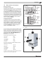
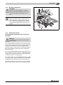
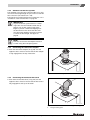
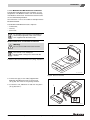
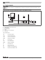
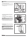
1.9.7 Installation of the horizontal flue
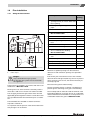
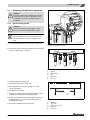
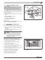
V The standard flue is suitable for lengths upto 660 mm
(Æ fig. 26). For longer flue runs upto 12.0 m, extension
air/flue ducts are available.
2
1
NOTE
Use the wall-mounting template to help you
mark the position of the side flue opening.
4
3
5
7215 3100-26.1TD
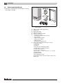
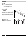
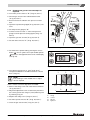
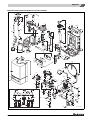
Fig. 26 Installation with horizontal flue gas turret
1.
2.
3.
4.
5.
Maximum length
Terminal assembly
Flue turret
Finishing kit
Outer wall
1.9.8 Flue duct preparation and assembly
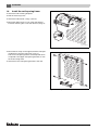
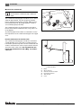
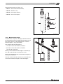
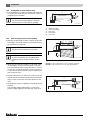
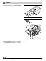
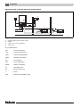
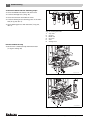
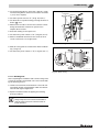
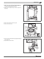
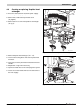
V Measure the flue length L. Refer to figures 27 and 28.
The length L is from the centre line of the flue turret to
the outside face of the wall.
L
NOTE
The flue must be inclined from the boiler.
A
NOTE
An inner flue finishing kit is provided which
should be fitted to the ducts before assembly.
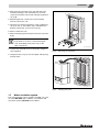
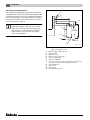
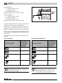
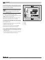
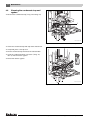
V When just the terminal assembly is to be used, measure the length L from the raise ring back (Æ fig. 29).
The overall measurement for the outer duct is L minus
70 mm. The overall measurement for the inner duct is
L minus 50 mm. Ensure that the cuts are made square
and a free from burrs.
7215 3100-27.1TD
Fig. 27 Flue length - rear
item A = 150 mm without the use of a wall-spacing frame
item A = 185 mm with the use of a wall-spacing frame
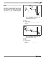
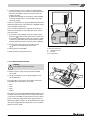
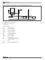
V If the final flue piece is an extension, measure from the
formed end, back. As before the final measurement are
minus 70 mm for the outer and minus 50 mm for the
inner.
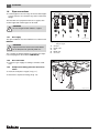
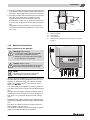
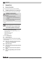
L
V Assemble flue system completely. Push the ducts fully
together.
The assembly will be made easier if a solvent free
grease is lightly applied to the male end of the ducts.
7215 3100-28.1TD
Fig. 28 Flue length - side
24
Buderus 500-24C/28C - Subject to modifications resulting from technical improvements