1
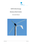
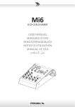
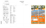
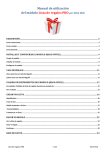
FORTIS Wind Energy Alizé Wind Turbine Instruction Manual No part of this document may be reproduced or transmitted in any form or by any means, electronic or mechanical, including photocopying and recording, for any purpose without the express written permission of FORTIS WIND ENERGY. FORTIS WIND ENERGY reserves the right to make changes to any and all parts of the documentation, at any time, without obligation to notify any person or entity of such changes. © Copyright 2013, FORTIS Wind Energy all rights reserved. Fortis Wind BV 9751 AC Haren The Netherlands Manual Alizé Page 2 of 42 § Table of Contents § Index: Page Important security notice 6 1 Introduction 7 2. Selection of location and tower height 7 3 Assembling Power head: 8 4 5 6 3.1 - Generator 8 3.2 - Rotor blades 8 3.3 - Tail and Tail vane 8 3.4 - Mast Adapter 8 Instructions Mast: 9 4.1 - Producing a Mast yourself 9 4.2 - Foundations 9 4.3 - Installation preparations 10 Electric Installations: 11 5.1 - Transmission lines 11 5.2 - Rectifier & Battery Charging system 11 5.3 - Grid connection 12 5.4 - Batteries 12 5.5 - LC Filter 12 5.6 - Brake switch 12 Final assembly of system/electronics: Manual Alizé 13 Page 3 of 42 § Table of Contents § 7 8 Erecting the turbine in the upright position: 7.1 - Safety first 14 7.2 - Conditions during installation 14 7.3 - The installation erection procedure 14 7.4 - Guy wire tensioning 15 7.4.1 - Determining the proper frequency of the cable 16 7.4.2 - How to oscillate the cable 16 7.4.3. - Procedure for tensioning the cable 16 7.4.4 - Cautions, Hints and Suggestions 17 7.5 17 - Start-up procedure Appendix: Manual Alizé 14 18 8.1 - Torque specifications 18 8.2 - Required tools 19 8.3 - Technical data Alizé 20 8.3.1 - Power Curve Alizé 21 8.4 - Trouble shooting list 22 8.5 - Maintenance/ checklist 23 8.6 - Drawings foundation 24 8.7 - Drawing foundation blocks 25 8.8 - Drawing Mast 26 8.8.1 - Drawing mast specifications 27 8.8.2 - Drawing mast specifications 28 Page 4 of 42 § Table of Contents § 9 8.8.3 - Drawing mast specifications 29 8.8.4 - Picture of Alizé with guyed tower 30 8.9 - Dimensions Alizé wind turbine 31 8.10 - Tail assembly 32 8.11 - Tail & Vane of Alizé 33 Parts list 34 9.1 - GFI – 10K2 Grid Feed Inverter 35 9.2 - Electric schema Alizé to 3 phase network 40 10 Safety and control procedures 41 11 Declaration of Conformity 42 Manual Alizé Page 5 of 42 Important security notice Note: For successful operation of your wind turbine, it is essential to read this manual carefully prior to installation. Important security notice This Instruction Manual contains important operational guidelines and security considerations that require your attention. Before installation, it is essential that the user first studies this user's manual in detail and keeps in mind the safety matters that need attention. During user installation and operation one must refer to this handbook's documentation. If you are unfamiliar with installation as shown below, DO NOT CONTINUE and let a qualified Technical Engineer proceed with correct installation. Failure to comply with the guidelines and instructions will void your warranty. WARNING! Do not change anything of the wind turbine parts or do not paint the blades. If you do so you lose the right of warrantee. Any change can have effect in the behaviour of the wind turbine. Manual Alizé Page 6 of 42 1. Introduction Thank you for choosing FORTIS Energy systems. Your choice means proven reliability, low maintenance costs (if any) and the convenience of an independent power supply. FORTIS Wind turbines are designed to withstand most of the environmental condition at the earth. Even Siberian as well Tropical conditions can have benefited from the reliable power the FORTIS Wind turbine produces. FORTIS tests their systems under the worst possible weather conditions. FORTIS Wind turbines will be installed at all over the earth Therefore the FORTIS products are designed on such a way that they can be installed and erected successfully with a minimum of tools and technical know-how. Also unskilled people are capable of maintaining the system with a minimum of tools and knowledge. A FORTIS-system is almost always composed of various components: the wind turbine itself is only one component of this system. We can supply controllers for battery charging and for grid connection. For hybrid systems, controllers are available to couple a photovoltaic solar generator or to a diesel or petrol generator together to a FORTIS Wind turbine. In other words, the possibilities with an FORTIS Wind turbine are endless in the sense that they can be adapted to suit almost every conceivable application. 2. Selection of location and tower height For a good performance of your wind turbine it is necessary to install the FORTIS ALIZE in such a way that the wind has an uninterrupted flow from all directions to the propeller. Any obstructions such as trees, hills or buildings, even if they somewhat lower than the wind turbine, will cause “rough” air Manual Alizé current which seriously decrease the generator output. The rough air current have lost a large part of their original power and continually shift both horizontally and vertically which may cause the generator to vibrate to some extent. The higher the wind turbine is situated the better, as the air current are smoother and steadier further from the ground. All of these factors should be considered when selecting a satisfactory location for the wind turbine. Read more about this issue in the publication of Paul Gipe: “Windpower Renewable Energy for Home, Farm and Business” Chelsea Green Publishing Company; www.chelseagreen.com The wind turbine hub should be mounted at least 10 meters above any obstruction within 400 meters Another important fact to keep in mind is that the wind turbine should be mounted as close as possible to the battery bank. The further it is mounted from the battery bank, the greater the loss of energy in the wires. In order to minimize this loss of energy in the wires, we have provided information about the wiredimensions in section 5.1. This list also shows that if the wind turbine is placed further from the battery, the wiring costs will be higher. There are two reasons for this: firstly, a greater length of wire will be required and secondly, the diameter of the wire will have to be larger. Install the wind turbine close to the house and high enough to receive an unobstructed sweep of the wind Page 7 of 42 3. Assembling the power head The FORTIS ALIZE power head consists of the following parts; - Generator - Rotor blades - Tail and Tail vane - Frame/Mast adapter 3.1 Generator When you first open the crate, check the contents carefully starting with the generator and its support-frame. First make a visual check to determine any existing scratches, dents or cracks. Then rotate the shaft of the generator by hand. This must rotate smoothly (<10.0N/m). If it does not, check whether there is no short-circuit in one of the phases. (out coming wires might be connected somehow) Normally the generator is already attached to the support frame with a specified torque (appendix 7.1) so there is no need to tighten the eight M14 bolts. The power head is bolted to the crate it is transported in, before you undo these bolts, remove all other components inside the crate. We advise to wait with unpacking the power head till its mast is ready to receive it. The power head can then be moved straight from the crate on to the mast top. 3.2 Rotor blades The large cardboard box contains the rotor blades and parts of the tail frame. Unpack the rotor blades and make a visual check for any existing cracks or scratches. When nothing is visible at all, the blades can be mounted on the hub. Every single blade has its unique fit to the hub, and in addition to this the blades are marked with a number (serial number + blade nr. 1, 2 or 3 ) that corresponds with number on the hub plates. The numbers are Manual Alizé always on the front side of the hub plates. The flat side of the blades should face the wind as is the front side of the hub. There is only one way to fit the rotor blades to the generator. The bolts are positioned in such a way that assembling in another way is not possible. First assemble the rotor blades to the hub plates. Use a flat and clean area to work. Fix the rotor blades with the 3x M12 bolds. Assemble first the complete tower and generator with tail. The final part should be the rotor blade set. You need 3 people to put the rotor over the 3 x 3 M14 bolds on the generator. It’s possible that you need some pressure to put the rotor to the generator. Use a gummy hammer or use a piece of wood together with a heavy steel hammer to move the rotor to the generator. 3.3 Tail vane The tail vane assembly is composed of 3 sections. The 3 parts are the tail vane which is bolted inside the crate with hinge section and the tail beam which is packed together with the rotor blades in the cardboard box. The tail & vane can be fully assembled according to the instructions on page 34. Note: on the stainless steel shaft of 22 mm, there are 2 lock pins assembled and a glider ring. When you assemble the tail hinge to the frame don’t forget this ring. It avoids noise when tail furls. Put this ring between the two stainless steel bushes at the top. 3.4 Mast adapter The mast adapter is a part of the support frame supplied with the ALIZE system. Before you bolt it on top of the mast, make sure that it fits well in the support frame and can be rotated by hand. The azimuth bearing is a special bearing with high friction. It is normal to use some force rotate the mast adapter. Page 8 of 42 When any parts of the wind turbine show damage that might have occurred during transportation, inform your local supplier or FORTIS directly about this. If you do not report such damage or the turbine is already in operation, you lose the right to your warranty ! In most cases FORTIS advises the use of the guyed steel tubular mast as it is inexpensive, easy to build, easy to erect and FORTIS can provide all the required calculations. These calculations can be very important when planning permission has to be obtained. The drawings for a guyed steel tubular mast are provided in this manual. The masts are designed according to a modular system with 6 – 8 m modules, guyed every 12m. (Appendix 8.8) 4 Instructions Mast 3.1 -Producing a Mast yourself 4.2 Foundations 3.2 -Foundations 3.3 -Installation preparations When FORTIS has delivered the tower for your wind turbine this owner’s manual include a full set of drawings and specifications of the foundation. If you plan to produce your own guyed tower follow the instructions below. 4.1 Producing a mast yourself FORTIS can deliver for your wind turbine a steel tube towers of 12,15,18 and 24 m high and guyed towers of 18, 24 and 30 m high. Producing a mast for your FORTIS wind turbine is relatively simple. Various constructions are possible but in most cases a steel tubular mast with guy wires is used. It is also possible to use wooden poles, free standing steel tubular masts or free standing lattice masts. Even concrete masts are a possible option. On request we give forces at the top of the tower, which enable you to make the necessary stress calculation of your own build tower. For these stress calculations you take a safety factor of at least 2 (two) for the peak loads and at least 10 (ten) for the amplified (fatigue) loads. FORTIS does not take any responsibility for own build towers and its foundation based on the tower top loads and drawings supplied by Fortis Manual Alizé As there is such a wide variety of masts possible, we only describe here the foundations for the standard guyed steel tubular mast according to the standard FORTIS design. There are three ways to make a proper foundation for the mast and guy wires: 1) The first type of foundation is for very soft and unstable ground: for this type, concrete blocks of a certain weight have to be used. Drawings for this type of foundation are provided in appendix 8.6. 2) The second type of foundation is for rocky ground: this type requires the use of rockbolt's for the tower and the guy wires. Make sure that the rocks are heavy enough. FORTIS can provide and specify the rockbolts on request. The size and weight of the rocks must be about the same as the concrete blocks described in the foundation drawings. 3) The third type of foundation is for medium soft but stable ground: for the guy wires, earth-screw-anchors are used and for the mast, a small concrete block will be sufficient. The earth-screw-anchors can be Page 9 of 42 specified and provided by FORTIS. The concrete block is the same as in appendix 8.6. 4.3 Installation preparations If you plan to use a steel tube tower or concrete tower you need a crane to erected the wind turbine. It is important to follow the instructions of the crane driver for safety reasons. In case of a guyed tower is used without help from professionals follow the instructions below. Before the mast is placed in a horizontal position, bolted to the base-plate, make sure the mast will be lifted towards the main wind direction. Lift and support the top of the mast in such a way that it is possible to assemble the support frame mast adapter to the mast top. Check if the mast adapter will rotate freely in to the support frame. Before you assemble the tower to the support frame, it is necessary to pull the power lines through the mast. For your FORTIS ALIZE machine, 3 flexible wires of 4 to 10 mm² will be needed to transport the power from generator. They must be pulled through the mast first, and then through the pull release glands in the support frame adapter. It is important to fix the cables in the glands very well because they have to carry the full weight of 18 to 24 m cable hanging in the tower The connecting wires must not get stuck anywhere on any part of the wind turbine. Make sure the wires can move and rotate freely inside the mast. Any possible problems in this area can cause a short circuit. For the power line use three wires with the same colour to indicate the three similar phases. These three wires must be connected to the three wires coming from the generator, the connector block can be found in the box that is attached to the generator. The order of connection is not important since all three lines are equal at both sides. When have connected the power lines and the tower to the support frame check the Manual Alizé generator and rotor hub rotating smoothly. You can rotate the hub with a force of 10 Nm. If not or if only with a very large force it is possible that there is a short circuit in the system. Check all the cables and connections Loose the power cable from the terminals. If it is still difficult to move the rotor hub there is short circuit in the generator, or something wrong with the generator bearings or another failure. Contact your agent or FORTIS. The next stage involves the guy wires: a standard FORTIS ALIZE mast according to FORTIS specifications is guyed every 10 12m, in four directions. Make a calculation of the length of each individual guy wire. The guy wire is prepared with a length of the calculated value + 1 m ( necessary for the connection with cable clamps). Then connect the guy wires to the mast and to its foundation. The only guy wire that cannot be connected is the one directly opposite the direction in which the mast is pointing. This guy wire should be connected when the mast is in the upright position. All guy wires are connected to the mast with a bow shackle and cable thimble, to the foundation with a cable thimble, rigging screw and at least twin cable clamps. The cable clamps must be fully tightened before lifting the mast. The next component to install is the tail vane. The tail assembling is given in section 3.3. The tail uses a stainless steel pin as spindle. This pin must slide into the tubular section of the tail frame where it passes through two Teflon bearings The Teflon bearings don’t need any additional lubrication; however, applying grease extends the life of the bearings to some extent. Next to install are the rotor blades as described above in section 3.2 Before assembling and close the polyester cover we will make an operational test of all vital components. Page 10 of 42 5 Electric Installations 5.1 -Transmission lines 5.2 -Voltage control/ dump load 5.3 -Grid connection 5.4 -Batteries 5.1 Transmission lines The electric wires have to be flexible and should not consist of a single solid copper core. Furthermore, the isolation wrapping of the wires should be UV-resistant (PVCisolation cannot stand UV light). Prevent the damaging of the electric wires by sharp edges. Any damage to the electric wires will lead to short-circuiting and the rotor will stop rotating, or even worse, the rectifier bridge might be destroyed because of too many amperes. Never let the wires hang with their full weight on the cable terminals. For the wire-gauge dimensions see the next table: The FORTIS ALIZE generator is a 3 phase generator and 3 electric wires are needed to connect the generator with the rectifier bridge. The maximum rectified current is 60A and peak voltage is 600 VDC. The working temperature of the components is –40°C to +50°C. Length (m) including tower Permitted power loss 240VDC systems < 5% > 10% 0 - 50 10 mm² 4 mm² 50 – 85 16 mm² 6 mm² > 85 25 mm² 10 mm² 450VDC system grid system 0 – 100 4 mm² 2,5 mm² 100 – 160 6 mm² 4 mm² > 160 10 mm² 6 mm² 5.2 Rectifier and battery charging system Use always the Fortis UN_Voltage Controller 240VDC and dumploads with the Alzé system for battery charging. The Fortis UN_Voltage Controller is an active rectifier to make DC form the AC power form the wind turbine. The microprocessor prevents over-charging of the batteries by switching power to the dump load. Manual Alizé When the batteries reach a threshold value, the microprocessor will keep the charge voltage constant and reducing the charging current by switching wind turbine power partly to dump load. It is advisable to mount the rectifier and microprocessor as close to the batteries as possible to minimise electrical losses. When the controller is housed in the same room as the batteries, the room must be well ventilated. Page 11 of 42 WARNING: The brake-switch short circuit the generator and will bring the rotor stop rotating up to wind speeds of 8 - 9 m/sec. Never let the brake switch on for more than ten minutes if the rotor does not stop because of high wind speeds. The generator can be overheated and destroyed. 5.3 Grid connection 5.5 LC Filter Grid connection is one of many options with a FORTIS system. In a grid-connected FORTIS ALIZE system, a Fortis GFI-10K2 Controller is used, all in one housing. The controller is needed to rectify the AC output of the wind turbine and to protect the inverter against peak voltages when the load is disconnected. The grid controller is build for max operation voltage of 400VDC. Use always the Fortis GFI-10K2 and Brake Switch for save operation with the dumploads supplied by Fortis. 5.4 Batteries Batteries need to be kept in a place with sufficient ventilation and no risk of freezing. Charged batteries can stand temperatures of up to minus 20°C, but uncharged batteries cannot withstand frost at all. Place the batteries underneath the voltage control in the same room if possible as this minimises energy loss in the wires. A battery is normally 2, 6 or 12 V so you need 120, 40 or 20 batteries connected in series for 240 VDC. Connect the minus terminal of one battery with the plus terminal of the other battery. The remaining terminals are the plus and minus of the 240 V battery group. For a FORTIS ALIZE we advise a minimum battery capacity of 500 -600 Ah – 240V (10 h), but a capacity of 1000 Ah is even better. For lead/acid batteries the charging / discharging current should not exceed 20% of the capacity.(preferable 10%) Manual Alizé Together with the Fortis UN_Voltage Controller a Filter is supplied. This filter is installed between wind turbine and the Fortis UN_Voltage Controller. See installation wiring diagram 9.1.1. The filter is needed to avoid EMC noise in the cable from wind turbine to controller. 5.6 Brake switch As shown in wiring diagram 9.1.1. install a brake switch between Wind turbine generator and filter. In this way it is easy to stop the turbine in case of service or maintenance. The brake switch should be used only in case of service and not for emergency. The brake switch stops the rotor only at low wind speed. If the rotor keeps on turning when you put the brake switch on, release the brake switch within 10 minutes because the generator gets to hot in case of running is short circuit. Page 12 of 42 6. Final assembly electronics of system/ can either be a battery-bank, an inverter for grid connection or a Pump controller for water pumping. When mounting the controller, it is very important to choose a wall or surface which is non-conductive. The last component to connect is the consumption circuit. The consumption circuit IMPORTANT! There is, however, a specific sequence in which all the above mentioned connections must be made. This is very important as if the connections are not made in this order, the generator or controller can be damaged during the installation procedure. 1. Set brake switch on stop 2.Connect first always the dump load to the Fortis Controller before any other cable 3. Connect the 3 phase wire from generator to the controller 5.The batteries are the last component to be connected. If batteries are connected to the rectifier with volt and ampere meters, the volt meter must show the battery voltage as soon as they are connected. Before the wind turbine is erected and during the process of erection the three phases of the generator should be short-circuited. See wiring diagram 9.1.1. for Brake switch solution. Any other (temporary) way of shortcircuiting the three phases is allowed. It is not necessary to disconnect the batteries as they are protected from short-circuiting by the rectifier bridge. In addition to this, the batteries and any other consumption circuit should be properly fused. The fuse for the battery bank is supplied together with the controller. FORTIS advises to fuse all other consumption circuits in accord with their specifications as required. Check that all your connections are tightly and correctly connected. WARNING: Never connect the wires from the generator to the controller when the wind turbine is in operation. The open circuit voltage can be 10x the nominal voltage. This voltage can destroy the electronics. Manual Alizé Page 13 of 42 7 Erecting the turbine in the upright position 7.1 -Safety first 7.2 -Conditions during installation 7.3 -The installation 7.4 -Guy wire tensioning 7.5 -Start-up procedure 7.1 Safety first! Safety becomes very important when you consider the amount of serious damage and injuries that can be caused if a wind turbine topples over. Firstly, therefore, make sure that all the nuts and bolts of the wind turbine are tightened securely. We advise you to make one person responsible for the final overall check of all the nuts and bolts. Then let the same person check all the guy wires, rigging screws and foundations. During hoisting of the mast and wind turbine, everybody who is not directly involved with the process must keep a distance of (at least) mast height to the base plate! If a winch is used to erect the mast and wind turbine, only 2 men are necessary for the process; one for the actual lifting (jacking) and one to check the guy wires during erection. This person should make sure that the wires do not get stuck somehow or work themselves loose. 7.2 Conditions during installation It is not absolutely necessary to wait for a windless day to erect the mast of an FORTIS ALIZE wind turbine. The maximum wind speed for erection of the mast and wind turbine must not exceed 8m/sec. Only a FORTIS specialist who is present during Manual Alizé installation and erection can decide to proceed during higher wind speeds. Snowfall during installation is not necessarily a problem provided the snow is not sticking to the blades in large amounts. Snow or ice can cause rotor unbalance and thus damage the bearings of the generator. 7.3 The procedure installation (erection) The simplest way to erect a FORTIS-mast is to use a gin-pole. It is also the method most often used owing to the fact that it is usable under a wide range of circumstances. The length of the gin-pole must be somewhere between 1/2 and 1/3 of the length of the mast and a set of guy wires are required to prevent the mast from toppling to one side. If only one set of guy wires is used, connect this one guy wire to the top section of the gin-pole. When several sets of guy wires (at different levels) are used, a guy wire of every set must be connected to the top section of the ginpole. The last attachment point of the gin-pole is used for the cable of the winch or cablejack. The gin-pole is now held in place by at least four cables. Page 14 of 42 If it is possible to climb the mast when it is in a vertical position, we advise you to fix a rope to one of the blades to prevent the turbine from rotating. Even when it is possible to fix one of the blades with a rope, the three phases of the generator must always be connected (short-circuited). Be very careful with short circuiting the three phases when the rotor blades are moving, the voltage can easily reach dangerous levels !! The mast and wind turbine can now be erected! 7.4 Guy wire tensioning FORTIS has developed and recommends a method for setting the pretension on guy wires for all guyed towers. This simple procedure utilises the relationship between cable tension and the rate of cable vibration to give a preload which is proportional to cable size. It is based on the time required for the guy cable to complete 20 oscillations at the fundamental natural frequency. The approximate desired preloads for the various cable sizes are given below: EHS Cable size 1/2"(12mm) 7/16" 3/8"(10mm) 5/16"(8mm) 1/4"(6mm) Manual Alizé Preload 900 kg 675 kg 450 kg 337.5 kg 225 kg Page 15 of 42 7.4.1 Determining the proper frequency of the cable 1. Determine the length of the cable in metres from the guy bracket to the ground. 2. Divide this length by 3. 3. This gives the number of seconds which are required for the cable to make 20 complete cycles. 4. The process is very sensitive to this time period. Doubling the time required to make the 20 oscillations will result in 1/4 of the desired guy tension. We recommend therefore that the tension be adjusted until the time period is within 1 second of the recommended value. Calculation example: assume the following geometry: Height of guy fixing point = 12m Distance mast-foundation point = 6m This gives a total cable length of 13.4m. Dividing by 3 gives 4.5 seconds to complete the 20 oscillations. 7.4.2 How to oscillate the cable Any cable under tension will tend to oscillate at a certain natural or fundamental frequency which is dependent upon its tension, weight per meter and length. It is very important that the cable be moved back and forth at this frequency. The cable should trace out the pattern shown below in a regular, consistent way without whipping or distorting into other shapes. IMPORTANT: the frequency of oscillation is independent of the magnitude of oscillation. The idea is then to vary the tension of the cable until the proper frequency of oscillation is observed. 7.4.3 Procedure for tensioning the cable 1. Stand at one anchor and move the guy wire back and forth at its natural frequency. 2. Measure the number of seconds required for the cable to make 20 complete cycles. 3. Compare this time period with the recommended value. 4. If necessary, adjust the tension and go back to point 1. Manual Fortis Alizé Page 16 of 42 7.4.4 Cautions, hints and suggestions 1. Use your common sense. If the guy wires start making noises something like a guitar, they may well be too tight, so stop tensioning. You may be doing something incorrectly. 2. This procedure cannot be used under all wind conditions. If the wind speed is above 7m/sec., then your readings will not be accurate owing to the additional forces on the tower caused by the wind. Furling the wind turbine and stopping the rotor will reduce these additional forces and allow the use of this procedure in winds of up to 10 m/sec. 3. Do not use this procedure if the cable size is different from that recommended by FORTIS. For example, if the cable is larger, the result will be tension forces which are much greater than the recommended value. 4. On an FORTIS tilt-up tubular mast with 4 anchor points the cables which are at the same height but opposite to one another will tend to develop the same pretension. Both cables may require adjustment, however, for the tower to remain straight. 5. Do not attempt this procedure if ice is present on the cable. The extra weight of the ice will give incorrect results. 7.5 Start-up procedure Provided the wind turbine and mast are in the final position and there is some wind (more than 2,5 m/sec.), the start-up procedure can take place. Provided all the electric connections are correct, you can release the brake switch and he will automatic run the start-up procedure. If there is sufficient wind, the turbine will start to rotate and power will be produced. Evidence of power being produced is provided as soon as the ampere meter of the voltage control indicates anything above zero. When the controller is not equipped with volt and ampere meters, a multi meter can be used to check the system; even the slightest increase in voltage indicates power coming from the turbine. Do not be disappointed when the wind turbine does not start up in winds slightly above 3 m/sec., as it sometimes needs a short running-in period. When lifted the windturbine with generator short circuit, the wind turbine will start to rotate very slowly if there is sufficient wind,(less than 5 revs/min.). A final check can be made when the turbine is producing some power; check the voltage over a period of several hours. If all the connections are made correctly, the voltage will increase slightly although the difference may be minimal. Manual Fortis Alizé Page 17 of 42 8 Appendix: 8.1 Torque specifications Specification bolt/nut M16*50 M12*100 M14 nuts M18*60 M8* 40 M12*100 M14*50 M8*20 Manual Fortis Alizé Description Main shaft Rotor hub Rotor hub Mast top and mast flanges Tail vane Tail boom assembling Generator-chassis mounting Nose cone Torque (N/m) 120 Nm 80 Nm 100 Nm 100 Nm 50 Nm 80 Nm 120 Nm 10 Nm Page 18 of 42 8.2 Required tools The following tools are the minimum that required for successful installation: For tower assembling: Tractor or lifter to put tower sections together max weight tower section is 600kg One spanner and one socket wrench size 46 for M30 bolds To lift turbine with 18m tower max weight 2200kg Crane 16 m or 22m heigth: With 16 m the crane remains below rotorblades With 22 m the crane remains above rotorblades Rope nylon ( 20m) to remove lifting rope from crane For windturbine assembling: Set of spanners 10, 11, 13,17, 19 , 22 and 27 mm Socket wrench 10, 13,17 , 19 , 22 and 27 mm Hexagonal key 3 mm / 6mm Set of screw drivers for electrical terminals Rubber hammer 2,5 kg Multimeter (AC/DC voltages 0-500V) Ratchet Pincers Cable stripping tool and cutting tools For installing controllers and dumploads: Drilling machine with drills for wood or stone for wall plugs and screw size from 5 up to 12 mm Mechanical crimping tool for 6 and 10 mm2 cable Manual Fortis Alizé Page 19 of 42 8.3 Technical data ALIZE Max. output Output @ 11m/sec 10 kW 8.5 kW Wind speed: cut in rated survival 3,0 m/sec. 13 m/sec. 60 m/sec. Rotor blades: number diameter area airfoil tip speed ratio material 3 6,3; 6,6 or 6.9 m 31,2 / 34,2 / 37,4 m² NLF 416 7 Glass-fibre reinforced Epoxy Generator: type rated rpm. max. rpm. voltage frequency brushless permanent magnet 48-pole 300 350 100 - 400VAC standard other voltages on request 0-50 Hz Other: gearbox braking mechanism rotor speed control output control rectifiers hub type yaw system rotor position tower Head weight Manual Fortis Alizé none generator short circuit Inclined hinged vane microprocessor controlled rigid tail vane upwind steel tubular or guyed tower (height: 18, 24 or 30 mm) 385 kg Page 20 of 42 8.3.1 Power Curve ALIZE Rated Capacity (kW) 12 11 10 9 8 7 6 5 4 3 2 1 0 0 5 10 15 20 25 Windspeed at hub height [m/s] Type: Manufacturer : Rated power Output ( 11m/s) Fortis Alizé Fortis Wind Energy 10.000 Watt 8.500 Watt Rotor with fixed pitch Generator and hub Type Direction of rotation Upwind rotor with fixed pitch Pitch control Fixed pitch Hub Rigid Clockwise Number of baldes 3 Generator Permanent Magnet FORTIS Synchron Machine Length of blades 3,0 /3,15/ 3,30 m Grid feeding 3 x 230V by inverter Break systems Rotor Diameter 6,3 / 6,6 / 6,9 m Ecliptic safety system by inclined hinged vane 90° setting of tail short circuit of generator Rotor area 31,2 / 34,2 / 37,4 m² Yaw control Passive Aligned by Tail Vane Tower Various types of towers designed for different sites 18 - 36 m Weight tower head 385 kg Profile NLF 416 Manufacturer Fortis Wind BV Blade material Glass-fibre reinforced Epoxy Rated speed variable, max 350 rpm Rotor axis angle 100 Cone angle 0° Manual Fortis Alizé Page 21 of 42 8.4 Trouble shooting list The rotor blades run very slowly, possible causes: - Insufficient wind - Short-circuit in the electrical wires * - Diodes are damaged * - The rotor is mounted in the wrong way (the flat side has to face the wind) The wind turbine shakes, possible causes: - The rotor blades are not in balance * (please stop the wind turbine immediately) - Own frequency of blades - The rotor blades are not running on the same plane (the hub is misaligned) * Batteries are discharged, possible causes: - Owing to a short circuit the wind turbine is not able to produce power * - Damaged diodes, no power is coming from the wind turbine * - Batteries are old or in a bad condition and are unable to store power Rotor blades run very fast, possible causes: - Power lines coming from the wind turbine are disconnected - Most of the time no problem at all !!! * Contact FORTIS Wind Energy or your local supplier (FORTIS agent) BE ALWAYS AWARE ABOUT SHAKING OF THE WIND TURBINE: The wind turbine can shake because of its own frequency at a specific speed The shaking becomes worse at higher speed , this means unbalance 'stop wind turbine' Also shaking of tail or tower top section can mean unbalance in rotor Blades Manual Fortis Alizé Page 22 of 42 8.5 Maintenance / checklist In principle, FORTIS wind turbines do not require any maintenance at all. On the other hand, it would be unwise not to check the wind turbine occasionally. FORTIS advises that you should check the wind turbine at least twice a year. The following points should be checked: - Check noises; the noise level should not have increased and should sound normal - Check nuts and bolts; they might have worked themselves loose - Check the yaw bearing and the bearings of the tail blade, they must be able to move smoothly; if they do not, apply some grease to the bearings - Check the electrical wires that are hanging through the inside of the mast; the tension must not be too high; this can occur if the wires have been wound too far. - Check the leading edge of the blades, small damages can be caused by small objects carried by the wind; such damages will speed up the process of wear and tear and should be repaired - Check the tension of the guy wires, if you have a guyed tower, in the first 6 months regular. - Check if the turbine, tail or tower is shaking more than usual. If this shaking occur only at a specific low speed this means own frequency. If it become stronger with higher wind speed, stop wind turbine and contact your dealer or agent or contact Fortis direct. Manual Fortis Alizé Page 23 of 42 8.6 Drawing Foundation Manual Fortis Alizé Page 24 of 42 8.7 Drawing foundation blocks Manual Fortis Alizé Page 25 of 42 8.8 Drawing mast Guyed tower Alizé Manual Fortis Alizé Page 26 of 42 8.8.1 Drawing mast specifications Manual Fortis Alizé Page 27 of 42 8.8.2 Drawing mast specifications Manual Fortis Alizé Page 28 of 42 8.8.3 Drawing mast specifications Manual Fortis Alizé Page 29 of 42 8.8.4 Picture of Alizé with guyed tower Manual Fortis Alizé Page 30 of 42 8.9 Dimensions Alizé wind turbine Manual Fortis Alizé Page 31 of 42 8.10 - Tail assembly Tail beam Tail hinge section Tail Vane Manual Fortis Alizé Page 32 of 42 8.11 Tail & Vane of Alizé Tail Vane mounted on left side of tail beam. (seen from the front of rotor blades) Note: TOP remark on upside tail hing section. Place the Teflon glider ring on top of the shaft. On top and bottom mount the lock pins. (See also note on chapter 3.3). Manual Fortis Alizé Note: Tail hing section should turn to the right. (seen from the front of rotor blades) Page 33 of 42 9. Parts list 9.1 GFI – 10K2 Grid Feed Inverter 9.2 Electric schema Alizé to 3 phase network Note: For detail description of the GFI-10K2 Inverter see Manual: Version 2.4 - 716004 GFI Installers Manual (GB) Brake Resistor with Connection Cable: Version 2.0 - 716005 DL-35K - DL-57K user manual_GB Manual Fortis Alizé Page 34 of 42 9.1 GFI – 10K2 Grid Feed Inverter Manual Fortis Alizé Page 35 of 42 Technical data GFI-10K2 -----------------------------------------------------------------------------------------------------------------------------------GENERAL Description Integrated 3-phase inverter. Operating temperature -20 °C to 60 °C ambient, full power up to 40 °C ambient air temperature. Storage temperature -20 °C to 60 °C Relative humidity protected against humidity and condensing air by PCB coating Protection degree IP42 Safety class class I (metal enclosure with earth connection) -----------------------------------------------------------------------------------------------------------------------------------INVERTER INPUT Nominal power 10.000 W Continuous power @ 40 °C 10.000 W Operating voltage 40-340 V AC Nominal voltage @ full load 220-340 V AC Maximum voltage 390 V AC Rated current 3 x 20 A (rms) Maximum current 3 x 30 A (rms) Frequency range 0-150 Hz -----------------------------------------------------------------------------------------------------------------------------------DUMP LOAD OUTPUT Nominal power 10.000 W Maximum power (120sec duration) 15.000 W Maximum current 2x15A -----------------------------------------------------------------------------------------------------------------------------------GRID OUTPUT (AC) Voltage 230 V AC 3-phase + N +PE (4 Wire Y ±20%) Nominal power 10.000 VA Maximum power 10.500 VA Nominal current 3 x 16 Arms Frequency AC frequency 50 Hz: 45 - 55 Hz programmable AC frequency 60 Hz: 55 - 63 Hz programmable Nominal power factor > 0.99 at full power Reactive power 0.80 inductive – 0.80 capacitive Harmonic distortion THD < 3% THD DC current injection < 20mA AC connector AC glands on detachable plate in bottom of connection compartment. Fuse External fuses is mandatory, Recommended 25A (B) characteristics Not installing a properly rated fuse (Icu > 2.1 kA) will pose a safety hazard and will void the warranty of the inverter. Maximum inrush current 28.2A Short circuit L-N 150A peak/12.9A RMS(3 cycl) during 8ms Short circuit L-L 298A peak/21.8A RMS (3 cycl) during 4ms ----------------------------------------------------------------------------------------------------------------------------------SYSTEM INFORMATION / DIAGNOSTICS / COMMUNICATION User interface 10 status LED’s or TFT Touch display Inverter external communication 1 USB Interface Manual Fortis Alizé Page 36 of 42 Additional technical data for GFI inverter ------------------------------------------------------------------------------------------------------------------------------------SAFETY DEVICES Island protection An AC fault in any of the phases will disable the inverter. Redundant voltage and frequency window monitoring (QNS). Independent cut-off by means of 2 pole relay and solid state switch (ENS) according to VDE 0126-1-1:2006. Temperature protection thermal switch off at inverter internal over temperature Safety devices AC grid side Integrated RCD (AC/DC sensitive), trip levels 30 mA Jump 300 mA continuous Voltage / Frequency window, AC current limiting, DC current injection protection, transients surge protection (varistors class lll) Reclosure time wait 10 - 300 s (country selection dependant) after AC grid fault ----------------------------------------------------------------------------------------------------------------------------------SYSTEM INFORMATION / DIAGNOSTICS / COMMUNICATION RS485 communication channels (DVE-SBUS) Standard Wind direction / Wind (anemometer) interface Standard 3 (1 x Wind direction / 2 x Wind speed) Vibration sensor (VM102) Standard 1 Galvanic isolated user input (digital / analogue) Standard 8 x DI / 4 x AI Relay contacts user output (change over) Standard 3 x changeover Free space for customer parts on internal DIN-rail Standard Thermal sensor input (NTC/PTC) Standard 2 (1 x Generator / 1 x Dump load) Prepared for 4.3” TFT colour touch display Yes, optional add-on ----------------------------------------------------------------------------------------------------------------------------------NORMATIVE STANDARDS APPLIED Emission Harmonics Flicker Immunity Electrical safety Grid compliance Manual Fortis Alizé EN 61000-6-3 EN 61000-3-2 EN 61000-3-3 EN 61000-6-1 EN 60950 EN 50438 DIN VDE0126 DIN VDE AR-N 4105 G83/2 G59/2 /3 DK5940 Page 37 of 42 Dimensions: 644 x 819 x 370mm (bxhxd) Manual Fortis Alizé Page 38 of 42 IMPORTANT! Dump load matrix for Alizé wind turbine: Battery charging Alize 240V Dump load: 2x 6 kW / 230V Connection: Parallel Cable type: Length: Manual Fortis Alizé Single Phase 230V/50Hz 2x 6 kW / 230V Serial 3 Phase 400V /50Hz 2x 6 kW / 230V Serial Page 39 of 42 9.2 Electric schema Alizé to 3 phase network 10 Safety and control procedures ___________________________________________________________________________________________________________________ www.fortiswindenergy.com Page 40 of 42 WARNING: What’s dangerous! 1. 2. 3. 4. 5. Spinning Rotor High tension on electric wires Falling from tower Crane drops tower/wind turbine Gin pole/winch fault during erection of guyed tower Choose a supervisor of the team who will be responsible for these procedures Do not fix a rope to the rotor blades and tower during erection. It can damage the blades. Only a rope which can mover free around the tower is possible Before erection check if the generator is on the brake or on short circuit Check all bolds and nuts of the wind turbine and tower before erection if they have the right tension During erection all persons has to be at a distance from the foundation of more than the height of the tower All electrical connections and electronics installation has to be completed before erection. If possible the final connection should be the plug in the tower base Check if the earth cables are connected well Check if isolation of all cables is made well Ask crane drive for their safety and control procedures and their responsibilities Do not erect the windturbine during high winds. The crane driver has always instructions at which max wind speed he can operate safely Never climb into the tower when the wind turbine is not set on the brake. This will be very dangerous Never disconnect any electrical wire if the wind turbine is not set on the brake When climbing in the tower use always position belts and full body harnesses. Follow always the rules. Get aware of the local rules of save work If you use a gin pole for erection read first the special instructions in the manual Do you have insurance public liability insurance product warranty and liability professional indemnity erection all risks 11 Declaration of Conformity ___________________________________________________________________________________________________________________ www.fortiswindenergy.com Page 41 of 42 Declaration of Conformity According to type II-A without external approval Declaration of approval (according to appendix II-A of the machine guideline) Manufacturer: Fortis Wind Energy Address: Botanicuslaan 14, 9751 AC Haren, The Netherlands, Herewith declare under our sole responsibility that the products: - Passaat 1.4 kW - Montana 5 kW - Alizé 10 kW to which this declaration is regarded, confirms to the : - Construction products (89/106/EEG); - the low voltage electricity (73/23/EEG); - the EMC (89/336/EEG) and - the machinery (98/37/EEG) - IEC 61400-2 "Design requirements for small wind turbines" which has been adopted as European Standard EN 61400-2 guidelines of the EEG. Instructions for installation, operation and maintenance are according to the Instruction Manuals. Haren, 2011-08-22 Johan Kuikman CEO Fortis Wind Energy ___________________________________________________________________________________________________________________ www.fortiswindenergy.com Page 42 of 42