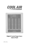
1
Models LBW-420 (115 VAC powered) and LBW-420-1 (24 VDC powered) Ammonia Leak Detectors 8-1 CAUTION & SYMBOL DEFINITIONS: CAUTION: Gives detailed description of different situations to avoid or not avoid for the proper operation of the equipment. WARNING: RISK OF ELECTRIC SHOCK. DO NOT REMOVE COVER. NO USER SERVICEABLE PARTS INSIDE. REFER TO QUALIFIED SERVICE PERSONNEL. AVIS: RISQUE DE CHOC ELECTRIQUE. NE PAS ENLEVER LE COUVERCLE. AUCUN ENTRETIEN DE PIECES INTERIEURES PAR L'USAGER. CONFIER L'ENTRETIEN AU PERSONNEL QUALIFIE. LBW-420 and LBW-420-1 Ammonia Leak Detectors TABLE OF CONTENTS IMPORTANT—READ THIS FIRST ........................................................ 4 CAUTIONS ................................................................................................. 4 AVOIDING NUISANCE ALARMS ................................................................ 4 STANDARD FEATURES ........................................................................... 6 AVAILABLE OPTIONS ............................................................................. 7 PARTS DESCRIPTION .............................................................................. 8 FRONT PANEL DISPLAY ............................................................................ 8 AMMONIA SENSOR.................................................................................... 9 FRONT PANEL-MOUNTED CIRCUIT BOARD ............................................ 9 SERVICE SWITCH (SERVICE MODE) ...................................................... 10 THE “ENTER”, “UP”, AND “DOWN” PUSHBUTTONS ......................... 11 ROTARY SELECTOR SWITCH ................................................................. 11 ENCLOSURE-MOUNTED CIRCUIT BOARD .............................................. 13 RELAYS ................................................................................................... 16 RELAY STATUS LEDS ............................................................................. 16 EXTERNAL CONNECTIONS ..................................................................... 17 4–20 MA ANALOG OUTPUTS .................................................................. 17 INSTALLATION AND SETUP................................................................ 21 EXAMPLE APPLICATION......................................................................... 23 REMOTE SENSING...………………………………............................23 REMOTE ALARM……….…………………………............................24 BACKUP BATTERY……..…………………………............................26 PROGRAMMING AND OPERATION................................................... 27 SETTING THE DESIRED DISPLAY MODE ................................................ 28 PROGRAMMING THE AMMONIA PRE-ALARM AND ALARM SET POINTS ................................................................................................................. 28 PROGRAMMING THE HIGH AND LOW EXTERNAL TEMPERATURE SET POINTS .................................................................................................... 29 PROGRAMMING THE EXTERNAL TEMPERATURE ALARM STATUS ....... 30 PROGRAMMING THE SENSOR GROUP NUMBER..................................... 30 PROGRAMMING THE EXTERNAL TEMPERATURE SENSOR INSTALLATION STATUS .................................................................................................... 31 Page 2 Rev. 8-1 7/28/2014 Copyright © 2003-14 by Cool Air Incorporated. All rights reserved. LBW-420 and LBW-420-1 Ammonia Leak Detectors PROGRAMMING THE AMMONIA LEVEL 4-20 MA RANGE ..................... 32 AMMONIA LEAK INDICATION ................................................................ 34 MESSAGE CODES .................................................................................... 35 4-20 MA ERROR INDICATION .................................................................. 35 TEST AND CALIBRATION .................................................................... 37 TESTING THE DETECTOR ....................................................................... 37 CALIBRATING THE DETECTOR............................................................... 38 TECHNICAL SUPPORT .......................................................................... 40 WARRANTY.............................................................................................. 41 LBW-420 SPECIFICATIONS .................................................................. 42 Page 3 Rev. 8-1 7/28/2014 Copyright © 2003-14 by Cool Air Incorporated. All rights reserved. LBW-420 and LBW-420-1 Ammonia Leak Detectors IMPORTANT—READ THIS FIRST PLEASE READ AND UNDERSTAND THIS SECTION BEFORE INSTALLING AND OPERATING THE LBW-420 DETECTOR CAUTION: Operating the detector in lower temperatures will slow the detector response rate, and high humidity or excessive heat can cause the “Minimal Concentration” LED to light. After applying power, test the detector to ensure it is operating correctly. Be sure the detector has been powered for at least 8 hours before testing. If storing this manual in the detector enclosure, be sure not to lay it flat over the circuit boards, as this might result in damage to components from excessive heat. Fold the manual and store it in the space between the enclosure-mounted circuit board and the enclosure wall. Adequately cover the detector sensor during washdown, and avoid spraying the washdown liquid directly onto the sensor. Avoiding Nuisance Alarms To avoid nuisance alarms, place the detector in service mode before: Programming set points, external temperature alarm status, and external temperature sensor installation status. Performing maintenance, repairs, testing, or calibration. Performing maintenance on nearby compressor systems. Painting nearby. Performing refrigeration system maintenance. Washing down the area. Removing the ammonia or temperature sensor. Page 4 Rev. 8-1 7/28/2014 Copyright © 2003-14 by Cool Air Incorporated. All rights reserved. LBW-420 and LBW-420-1 Ammonia Leak Detectors Furthermore, be sure of the following before placing the detector in normal operating mode: The ammonia concentration reading is below the pre-alarm set point. The temperature reading is between the high and low temperature set points (if an external temperature sensor is in use). A nuisance alarm will also occur if the external temperature sensor installation status is programmed to “F In” (installed) and an external temperature sensor is not installed. It is suggested that the high temperature set point be programmed above the normal operating temperature to avoid nuisance alarms. Page 5 Rev. 8-1 7/28/2014 Copyright © 2003-14 by Cool Air Incorporated. All rights reserved. LBW-420 and LBW-420-1 Ammonia Leak Detectors INTRODUCTION The Cool Air Incorporated LBW-420 is an AC powered state-of-the-art ammonia leak detector that detects and displays ammonia concentrations of 25 to 1000 parts per million (PPM). It comes equipped with a solid-state, long-life ammonia sensor that has a quick and accurate response to ammonia concentrations. The Cool Air Incorporated LBW-420-1 is a DC powered version of the LBW-420 ammonia leak detector (AC powered detector). The LBW420-1 incorporates a fully isolated DC to DC power supply, allowing the LBW420-1 to be powered from the same DC supply as the 4-20 mA monitoring circuits without concern for ground isolation. The LBW-420-1 requires a DC supply voltage between 21.6 and 26.4 volts DC +/- 10%. The LBW-420-1 can be configured to supply power to the 4-20 mA circuit(s) or can operate as a fully isolated 4-20 mA sensor. Refer to 4–20 mA Analog Outputs for more details. STANDARD FEATURES Both the LBW-420 and the LBW-420-1 come with these additional standard features: Programmable Alarm and Pre-Alarm (Early Warning) set points. Two 4-20 mA analog output signals, for ammonia level and external temperature, which can communicate directly with computer systems such as PLC’s. Normally-open, normally-closed contacts for communicating with common industry alarm systems. A NEMA 4X, UL-listed enclosure. Spare contacts for operating auxiliary equipment such as exhaust fans, king valves, compressors, and additional alarm systems. Page 6 Rev. 8-1 7/28/2014 Copyright © 2003-14 by Cool Air Incorporated. All rights reserved. LBW-420 and LBW-420-1 Ammonia Leak Detectors AVAILABLE OPTIONS In addition to the standard features, the LBW-420 and LBW-420-1 can be equipped with these options: A remote ammonia sensor with cable allowing the sensor to be located a maximum of 500 feet away from the detector. A high-low external temperature sensor with cable and programmable alarm set points for refrigeration or freezer applications. This sensor must be installed and active for the External Temperature 4-20mA signal to operate correctly. An external back-up battery to keep the detector working during loss of main power. A stainless-steel washdown tube installed over the sensor so that it does not get wet during washdown. A remote alarm light and horn box with a toggle switch to TEST/NORMAL/SILENCE the alarm. Contact Cool Air Incorporated technical support for more detailed information, or for purchasing, any of these options. Page 7 Rev. 8-1 7/28/2014 Copyright © 2003-14 by Cool Air Incorporated. All rights reserved. LBW-420 and LBW-420-1 Ammonia Leak Detectors PARTS DESCRIPTION Front Panel Display The front panel display is comprised of a digital display and a series of labeled indicating LED’s. The seven-segment, four-digit display indicates a variety of information, such as ammonia concentration and external temperature (if an external temperature sensor is in use), and more, depending on the position of the rotary selector switch. Ammonia concentration is displayed in parts per million (“P”) and temperature is displayed in degrees Fahrenheit (“F”). The LED’s provide an indication of ammonia concentration and alarm status at a glance. For information on how the display indicates ammonia concentrations, see the sections on ammonia leak indication Page 8 Rev. 8-1 7/28/2014 Copyright © 2003-14 by Cool Air Incorporated. All rights reserved. LBW-420 and LBW-420-1 Ammonia Leak Detectors . Ammonia Sensor The detector comes with a solid-state, long-life sensor that has a high sensitivity to amine compounds and a quick response to concentrations of ammonia. The sensor is protected by a flame arrestor, and has an integral heater and a ceramic base that is resistant to severe environments. Each ammonia sensor has a specific sensor group number, and this number must be programmed into the detector to detect and display ammonia concentration accurately. The detector is programmed at the factory with the correct sensor group number. The sensor group number can also be viewed on the front panel digital display. See the section on the rotary selector switch. However, if a new ammonia sensor is installed, the detector must be reprogrammed with the new sensor group number and recalibrated. See the section on programming the sensor group number. Front Panel-Mounted Circuit Board The front panel-mounted circuit board contains the controls necessary for programming and operating the detector. Each control is described in detail below. When the detector enclosure is open, this circuit board is on the left, attached to the front panel. Page 9 Rev. 8-1 7/28/2014 Copyright © 2003-14 by Cool Air Incorporated. All rights reserved. LBW-420 and LBW-420-1 Ammonia Leak Detectors Service Switch (Service Mode) The detector can be set to one of two modes: normal operating mode or service mode. The detector is in normal operating mode when the service switch is in the “OFF” position. When the service switch is in the “ON” position, the detector continues to function as usual, however the alarm, prealarm, and auxiliary relays are disabled. This allows the detector to be serviced, tested, and calibrated without tripping the alarm relays and setting off nuisance alarms. When the detector is in the service mode, the display will alternate between the sensor reading in PPM and “SEr” (service switch “on”). This is done as a reminder to set the switch back to “off” when service is done. Page 10 Rev. 8-1 7/28/2014 Copyright © 2003-14 by Cool Air Incorporated. All rights reserved. LBW-420 and LBW-420-1 Ammonia Leak Detectors The “ENTER”, “UP”, and “DOWN” Pushbuttons The “UP” and “DOWN” buttons are used for setting the digital display to the desired value, and the “ENTER” button is used for programming a value previously set on the digital display. These buttons are used when programming: the set points, the external temperature alarm status, the external temperature sensor installation status, and the sensor group number. They are also used during calibration of the detector. Rotary Selector Switch The rotary selector switch (labeled “MENU SELECT” on the front panelmounted circuit board) is used for performing functions such as: Setting the information displayed on the front panel Programming set points Displaying system information Calibrating the detector When the detector is in operation, this switch is typically set to position “0” to continuously display ammonia concentration, or to position “1” to display ammonia concentration and an external temperature (if an external temperature sensor is in use). If the switch is set to position “1”, the display will alternate between ammonia concentration and external temperature. Page 11 Rev. 8-1 7/28/2014 Copyright © 2003-14 by Cool Air Incorporated. All rights reserved. LBW-420 and LBW-420-1 Ammonia Leak Detectors Use the following chart to select the switch position for the desired function: Set the Rotary To: Selector Switch to: Display ammonia concentration in PPM 0 Display ammonia concentration in PPM and external temperature in °F (if an external 1 temperature sensor is in use) Display the firmware revision 2 Program the ammonia alarm set point 3 Program the ammonia pre-alarm set point 4 Program the external temperature alarm 5 status to “F AL” (active) or “F --” (inactive) Program the high temperature alarm set point 6 Program the low temperature alarm set point 7 Display the sensor group number 8 Display the offset (V50) 9 Note: If the rotary selector switch is left in a position other than “0” or “1” for more than 5 minutes, the digital display will begin to display ammonia concentration. If this happens, return the selector switch to the “0” position, then set the switch to the desired position. For example, if you set the rotary selector switch to position “3” to program the alarm set point, and if, after 5 minutes of inactivity the display reverts to displaying ammonia concentration, move the switch to “0”, then back to “3” to continue programming the alarm set point. Caution: Before closing the detector enclosure, be sure to return the rotary selector switch to position “0” or “1” to correctly display ammonia concentration, or ammonia concentration and external temperature. Page 12 Rev. 8-1 7/28/2014 Copyright © 2003-14 by Cool Air Incorporated. All rights reserved. LBW-420 and LBW-420-1 Ammonia Leak Detectors Additional functions are available through the rotary selector switch when the jumper (labeled “SET1”), located below the rotary selector switch on the front panel-mounted circuit board, is installed: To: Display ammonia sensor temperature Program the ammonia sensor Range Program the external temperature sensor installation status to “F In” (installed) or “F --” (not installed) Program the sensor group number Calibrate the detector Set the Rotary Selector Switch to: 1 3 5 8 9 Enclosure-Mounted Circuit Board The enclosure-mounted circuit boards differ between the LBW-420 and the LBW-420-1 to accommodate the differing Power connections. All other connections are identical. The Enclosure Mounted Circuit board contains the relays, output contacts and termination points for connecting to external equipment. When the detector enclosure is open, this circuit board is on the rear wall of the enclosure. The enclosure-mounted circuit board is shown in the following two pictures and described in detail below. Page 13 Rev. 8-1 7/28/2014 Copyright © 2003-14 by Cool Air Incorporated. All rights reserved. LBW-420 and LBW-420-1 Ammonia Leak Detectors Power (LBW-420) WARNING: RISK OF ELECTRIC SHOCK. DO NOT REMOVE COVER. NO USER SERVICEABLE PARTS INSIDE. REFER TO QUALIFIED SERVICE PERSONNEL. AVIS: RISQUE DE CHOC ELECTRIQUE. NE PAS ENLEVER LE COUVERCLE. AUCUN ENTRETIEN DE PIECES INTERIEURES PAR L'USAGER. CONFIER L'ENTRETIEN AU PERSONNEL QUALIFIE. Power for the LBW-420 must be a nominal 115 Volt AC circuit. Power is connected to terminal block J2. A safety ground terminal is also provided on terminal block J2. Page 14 Rev. 8-1 7/28/2014 Copyright © 2003-14 by Cool Air Incorporated. All rights reserved. LBW-420 and LBW-420-1 Ammonia Leak Detectors Power (LBW-420-1) Power for the LBW-420-1 must be a DC voltage between 21.6 and 26.4 volts with a current rating of at least 0.5 amps at 24 volts. Power is connected to terminal block J2. Jumper J3, Ammonia signal (LBW-420-1 only) Jumper J3 (ammonia signal) configures the LBW-420-1 to use either an external power supply for the Ammonia 4-20 mA circuit or to use an on board 30 volt DC supply for the 4-20 mA circuits. With the jumper in the leftmost position, connecting pins 2 to 3 (as shown in the picture) 4-20 mA power is supplied by the on-board supply. Page 15 Rev. 8-1 7/28/2014 Copyright © 2003-14 by Cool Air Incorporated. All rights reserved. LBW-420 and LBW-420-1 Ammonia Leak Detectors With the jumper(s) in the rightmost position, connecting pins 2 to 1 (opposite of picture) 4-20 mA power must be supplied by an external supply. Jumper J4, Temperature signal (LBW-420-1 only) Jumper J4 (temperature signal) configure the LBW-420-1 to use either an external power supply for the Temperature 4-20 mA circuit or to use an on board 30 volt DC supply for the 4-20 mA circuits. With the jumper in the leftmost position, connecting pins 2 to 3 (as shown in the picture) 4-20 mA power is supplied by the on-board supply. With the jumper in the rightmost position, connecting pins 2 to 1 (opposite of picture) 4-20 mA power must be supplied by an external supply. Jumpers Required Jumpers J3 and J4 must be installed in either position. If the jumper(s) are removed, the 4-20 mA circuit(s) will not function. Relays The detector has three miniature printed circuit board relays: the alarm, prealarm (early warning), and the auxiliary relays. The auxiliary relay operates at the same time as the alarm relay. In the normal operating mode, the relays are energized in a normally-open state. If a loss of power to the detector occurs, the relays will de-energize and the alarms, if connected, will sound. Relay Status LEDs Each relay has a surface-mounted LED associated with it that indicates the status of the relay. A relay is energized (a non-alarm condition) when its LED is lighted (green), and de-energized (an alarm condition) when the LED is not lighted. Page 16 Rev. 8-1 7/28/2014 Copyright © 2003-14 by Cool Air Incorporated. All rights reserved. LBW-420 and LBW-420-1 Ammonia Leak Detectors External Connections Contacts for external connections: 4–20 mA outputs for ammonia level and external temperature Auxiliary Relay contacts External temperature sensor input Alarm Relay contacts Pre-alarm Relay contacts (early warning) LBW-420 AC Power LBW-420-1 DC Power 4–20 mA Analog Outputs The detector has a two 4-20 mA analog outputs that allow it to communicate with external devices such as computers, PLCs, and digital displays. Both outputs conform to ISA S50.01 ratings, Type 2L and Type 2H (two-wire). The ammonia level detector output current (TB2, “Sensor 4-20mA” terminals on lower left of Enclosure Mounted Circuit Board) is proportional to ammonia PPM with the proportionality constant dependent on the range. The PPM value can be determined using one of the following formulae: PPM = 62.5 (I – 4) PPM = 50 (I – 4) PPM = 31.25 (I – 4) PPM = 25 (I – 4) PPM = 15.67 (I – 4) PPM = 6.25 (I – 4) 0 to 1000 PPM Range 0 to 800 PPM Range 0 to 500 PPM Range 0 to 400 PPM Range 0 to 250 PPM Range 0 to 100 PPM Range Where PPM equals ammonia concentration in parts per million and I equals the output current in mA. For example, if the current is 4 mA, then the ammonia concentration is 0 PPM. If the current is 20 mA, then the ammonia concentration is 100 PPM (100 PPM range), 250 PPM (250 PPM range), 400 PPM (400 PPM range), 500 PPM (500 PPM range), 800 PPM (800 PPM range) or 1000 PPM (1000 PPM range),. Page 17 Rev. 8-1 7/28/2014 Copyright © 2003-14 by Cool Air Incorporated. All rights reserved. LBW-420 and LBW-420-1 Ammonia Leak Detectors Wiring Diagram: LBW-420 For the LBW-420, the 4-20 mA output is a simple series circuit that includes the detector, a 24 VDC power supply, and the receiving device. It is recommended that a 24 VDC, low-noise power supply be used for this application, although power supplies providing a minimum of 10 VDC to a maximum 30 VDC can be used. The voltage drop across the detector and the receiver together must not exceed the power supply voltage. This circuit is shown in Figure 1 below: Figure 1. Page 18 Rev. 8-1 7/28/2014 Copyright © 2003-14 by Cool Air Incorporated. All rights reserved. LBW-420 and LBW-420-1 Ammonia Leak Detectors Wiring Diagram: LBW-420-1 with (1) – 24 VDC Power Supply For this configuration, with the jumper J3 in the leftmost position (which connects pins 2 & 3), power for the 4-20 mA circuit is provided by the LBW-420-1. This circuit is shown below. The power supply must supply all power for the LBW-420-1 plus the 4-20 mA circuit. Refer to the specifications page for the power requirements for the LBW-420-1. The voltage drop across the detector and the receiver together must not exceed the power supply voltage. This circuit is shown in figure 2 below: Page 19 Rev. 8-1 7/28/2014 Copyright © 2003-14 by Cool Air Incorporated. All rights reserved. LBW-420 and LBW-420-1 Ammonia Leak Detectors Wiring Diagram: LBW-420-1 with (2) – 24 VDC Power Supplies In this configuration, with the jumper J3 in the rightmost position (which connects pins 1 & 2), power for the LBW-420-1 is supplied by the 24 VDC power supply #1 only. The power supply must supply all power for the LBW-420-1. Refer to the specifications page for the power requirements for the LBW-420-1. The power for the 4-20 mA circuit is supplied by the 24 VDC power supply #2. The 4-20 mA circuit is a simple series circuit that includes the LBW detector, a power supply, and the receiving device. It is recommended that a 24 VDC low-noise power supply be used for this application, although power supplies providing a minimum of 10 VDC to a maximum 30 VDC can be used. The voltage drop across the detector and the receiver together must not exceed the power supply voltage. This circuit is shown in Figure 3 below: Page 20 Rev. 8-1 7/28/2014 Copyright © 2003-14 by Cool Air Incorporated. All rights reserved. LBW-420 and LBW-420-1 Ammonia Leak Detectors For both the LBW-420 and the LBW-420-1, the maximum allowable resistance in the receiving device must not exceed Rmax using this formula: Rmax = 50 (Vs – 7.5) where Vs is the supply voltage in volts DC for the 4-20 mA circuit. For example, with a supply voltage of 24 VDC, the maximum allowable resistance is 825 Ω. The External Temperature output current (if equipped) is located on TB3 “Spare” terminals on lower left of Enclosure Mounted Circuit Board and is proportional to the External Temperature with the proportionality constant dependent on temperature units (degrees F or degrees C). The External Temperature can be determined using the following formula: For units programmed in degrees F: Temperature = 10 (I – 4) – 50 -50F to +110F Range For units programmed in degrees C: Temperature = 5 (I – 4) – 50 -40C to +40C Range where I equals the output current in mA. For example, if the unit is programmed in degrees F and the output current is 12 mA, then the temperature is 30 degrees F. If the current is 4 mA, the temperature is -50F, and if the current is 20 mA, the temperature is +110 degrees F. Note that an optional External Temperature Sensor must be installed and External Temperature sensing must be active (see Programming the External Temperature Sensor Installation Status). INSTALLATION AND SETUP Caution: Do not apply power to the detector until instructed to do so. The detector comes with four mounting feet, packaged in the detector enclosure for shipment. Use the directions that accompany the mounting feet for mounting the detector enclosure. Page 21 Rev. 8-1 7/28/2014 Copyright © 2003-14 by Cool Air Incorporated. All rights reserved. LBW-420 and LBW-420-1 Ammonia Leak Detectors The detector should be mounted in a location where ammonia leaks are most likely to occur, such as near valve groups, compressors, and refrigeration coils. Be sure the detector is visible and easily accessible. Avoid locating the detector where it might be damaged during washdown. It is important not to install the detector (specifically the sensor) in designated smoking areas, as even a minute concentration of smoke will set off the alarm. WARNING: RISK OF ELECTRIC SHOCK. DO NOT REMOVE COVER. NO USER SERVICEABLE PARTS INSIDE. REFER TO QUALIFIED SERVICE PERSONNEL. AVIS: RISQUE DE CHOC ELECTRIQUE. NE PAS ENLEVER LE COUVERCLE. AUCUN ENTRETIEN DE PIECES INTERIEURES PAR L'USAGER. CONFIER L'ENTRETIEN AU PERSONNEL QUALIFIE. The detector is set at the factory to operate on 115 VAC. When power is applied to the detector, it will immediately go into alarm status and the display will show an unusually large ammonia concentration. This is normal. When the sensor warms to normal operating temperature (usually about a minute) the detector will return to a non-alarm status. For this reason, the detector must be placed in service mode before applying power to the detector to avoid nuisance alarms. The detector is calibrated and programmed at the factory. To program the detector for its specific installation, follow these steps in the order given: WARNING: RISK OF ELECTRIC SHOCK. DO NOT REMOVE COVER. NO USER SERVICEABLE PARTS INSIDE. REFER TO QUALIFIED SERVICE PERSONNEL. AVIS: RISQUE DE CHOC ELECTRIQUE. NE PAS ENLEVER LE COUVERCLE. AUCUN ENTRETIEN DE PIECES INTERIEURES PAR L'USAGER. CONFIER L'ENTRETIEN AU PERSONNEL QUALIFIE. Page 22 Rev. 8-1 7/28/2014 Copyright © 2003-14 by Cool Air Incorporated. All rights reserved. LBW-420 and LBW-420-1 Ammonia Leak Detectors 1. 2. 3. 4. 5. 6. 7. 8. 9. Open the detector enclosure and place the detector in service mode by sliding the service switch to the “ON” position. Apply power to the detector and allow the sensor to warm to normal operating temperature (at normal operating temperature, the display will read “0P” and all LEDs will be unlit). Program the ammonia pre-alarm (early warning) and alarm set points. See the next section on programming the ammonia pre-alarm and alarm set points. Program the external temperature alarm set points (if an external temperature sensor is installed). See the next section on programming the high and low external temperature set points. Program the external temperature sensor installation status to “installed” or “not installed”, depending on whether an external temperature sensor is installed. See the next section on programming the external temperature sensor installation status. Program the external temperature alarm status to “active” or “inactive”, depending on whether an external temperature alarm system is in use. See the next section on programming the external temperature alarm status. Set the detector to the desired operating display mode (typically “0” or “1”). See the next section on setting the display mode. Be sure the displayed ammonia concentration is below the programmed pre-alarm set point. If an external temperature sensor is installed, be sure the displayed temperature reading is within the programmed set points. Return the detector to normal operating mode by sliding the service switch to the “OFF” position. Test the detector to ensure it is operating correctly (but allow at least 8 hours after power is first applied to the detector before testing). See the section on testing the detector. LBW-420 or LBW-420-1 Example Application This schematic on the next page illustrates an example application. Page 23 Rev. 8-1 7/28/2014 Copyright © 2003-14 by Cool Air Incorporated. All rights reserved. LBW-420 and LBW-420-1 Ammonia Leak Detectors Page 24 Rev. 8-1 7/28/2014 Copyright © 2003-14 by Cool Air Incorporated. All rights reserved. LBW-420 and LBW-420-1 Ammonia Leak Detectors Remote Sensing Remote Sensing allows the ammonia sensor to be located remotely from the LBW-420. WARNING: FAILURE TO DISCONNECET POWER FROM THE LBW-420 COULD RESULT IN DAMAGE TO THE DETECTOR. This wiring diagram shows the connections from the LBW-420 to the Remote Sensor. All connections to the Remote Sensor are made at the LBW-420 TB7 on the Front Panel Circuit Board using 6 conductor shielded cable. Note specifically that the RED WIRE CONNECTS TO THE REM TERMINAL AND DOES NOT CONNECT TO THE “RED” TERMINAL. Also the shield and or drain conductor connect to the SHIELD terminal on the LBW-420 but do not connect to the Remote Sensor. The Remote Sensor device is pictured next to the wiring diagram. Page 25 Rev. 8-1 7/28/2014 Copyright © 2003-14 by Cool Air Incorporated. All rights reserved. LBW-420 and LBW-420-1 Ammonia Leak Detectors Remote Alarm Installation Remote Alarm replicates the audible and visible alarms of the LBW-420 at a remote location. This wiring diagram shows the connections from the LBW-420 to the Remote Alarm. Power for the Remote Alarm is derived from LBW-420 TB7 on the Front Panel Circuit Board. An alarm signal is derived from the LBW-420 enclosure-mounted circuit board. The Remote Alarm device is pictured next to the wiring diagram. Page 26 Rev. 8-1 7/28/2014 Copyright © 2003-14 by Cool Air Incorporated. All rights reserved. LBW-420 and LBW-420-1 Ammonia Leak Detectors Backup Battery Testing, Installation and Replacement The LBW420 or the LBW420-1 can be supplied with an optional Backup Battery from Cool Air Incorporated. This backup supply is good for approximately 1 ½ hours of operating time. During normal operation, the backup battery is not used but is kept trickle charged. In the event of a power failure, the unit will seamlessly operate off of the back-up battery. To test an existing or new battery, simple disconnect the leak detector power supply. The unit should stay in normal operation ad not turn off. If the unit turns off, check to make sure that the red and black wires are secure on the battery terminals and the circuit board terminals. If the wiring is good, the battery needs to be replaced. If the back-up battery needs to be replaced because it has either failed, or will not keep a charge, a new back-up battery can be ordered through your local leak detector supplier or directly from Cool Air incorporated. Prior to removing the old battery, disconnect the leak detector power supply, remove the black and red wires from the battery terminals, cut the wire cable strap (used primarily for shipping), and remove the battery from the Velcro mounting pad. Install the new battery onto the Velcro mount pad, remove the battery protector caps, plug the black wire into the black terminal, plug the red wire to the red terminal, and reconnect the leak detector power supply. Allow 24 hours of leak detector operation time before testing the new battery. PROGRAMMING AND OPERATION The LBW-420 and LBW-420-1 detector is easy to program and operate. Follow the instructions in this section to: Set the display mode Program the ammonia alarm set points Program the external temperature high and low set points Program the external temperature alarm status Program the sensor group number Program the external temperature sensor installation status This section also describes the operation of the front panel indication system. Page 27 Rev. 8-1 7/28/2014 Copyright © 2003-14 by Cool Air Incorporated. All rights reserved. LBW-420 and LBW-420-1 Ammonia Leak Detectors Setting the Desired Display Mode During normal operation, the rotary selector switch is typically set to position “0” or “1”. Set the switch to “0” to display ammonia concentration only, or to “1” to display ammonia concentration and external temperature (if an external temperature sensor is in use). If the rotary selector switch is set to “1”, the front panel digital display will alternate between ammonia concentration in PPM and external temperature in °F. Programming the Ammonia Alarm and Pre-Alarm Set Points The ammonia alarm and pre-alarm set points can be programmed from 25 to 800 PPM. To program the set points, follow these steps: WARNING: RISK OF ELECTRIC SHOCK. DO NOT REMOVE COVER. NO USER SERVICEABLE PARTS INSIDE. REFER TO QUALIFIED SERVICE PERSONNEL. AVIS: RISQUE DE CHOC ELECTRIQUE. NE PAS ENLEVER LE COUVERCLE. AUCUN ENTRETIEN DE PIECES INTERIEURES PAR L'USAGER. CONFIER L'ENTRETIEN AU PERSONNEL QUALIFIE. 1. 2. 3. 4. 5. 6. Open the detector enclosure and slide the service switch to the “ON” position. Set the rotary selector switch to position “3” (to program the ammonia alarm set point) or “4” (to program the ammonia pre-alarm set point). Press the “UP” or “DOWN” button until the desired set point concentration in PPM is displayed. Press and hold the “ENTER” button for at least 2 seconds. The new set point is now programmed. Return the rotary selector switch to the desired position. Be sure the ammonia concentration reading is below the pre-alarm set point, then slide the service switch to the “OFF” position and close the detector enclosure. Page 28 Rev. 8-1 7/28/2014 Copyright © 2003-14 by Cool Air Incorporated. All rights reserved. LBW-420 and LBW-420-1 Ammonia Leak Detectors Programming the High and Low External Temperature Set Points If the detector has an external temperature sensor, the high and low external temperature alarm set points can be programmed from -50°F to 110°F. For freezer applications, the set points are typically programmed to temperatures below 32°F, and for refrigeration applications, the set points are typically programmed to temperature above 32°F. It is suggested that the high external temperature set point be programmed above the normal operating temperature to avoid nuisance alarms. To program the high and low external temperature set points, follow these steps: WARNING: RISK OF ELECTRIC SHOCK. DO NOT REMOVE COVER. NO USER SERVICEABLE PARTS INSIDE. REFER TO QUALIFIED SERVICE PERSONNEL. AVIS: RISQUE DE CHOC ELECTRIQUE. NE PAS ENLEVER LE COUVERCLE. AUCUN ENTRETIEN DE PIECES INTERIEURES PAR L'USAGER. CONFIER L'ENTRETIEN AU PERSONNEL QUALIFIE. 1. 2. 3. 4. 5. 6. Open the detector enclosure and slide the service switch to the “ON” position. Set the rotary selector switch to position “6” (to program the high external temperature set point) or “7” (to program the low external temperature set point). Press the “UP” or “DOWN” button until the desired set point temperature in °F is displayed. Press and hold the “ENTER” button for at least 2 seconds. The new set point is now programmed. Return the rotary selector switch to the desired position. Be sure the external temperature reading is between the high and low temperature set points, then slide the service switch to the “OFF” position and close the detector enclosure. Page 29 Rev. 8-1 7/28/2014 Copyright © 2003-14 by Cool Air Incorporated. All rights reserved. LBW-420 and LBW-420-1 Ammonia Leak Detectors Programming the External Temperature Alarm Status The external temperature alarm status can be programmed to “active” or “inactive”, depending on whether an external temperature alarm system is in use. Follow these steps to program the external temperature alarm status: WARNING: RISK OF ELECTRIC SHOCK. DO NOT REMOVE COVER. NO USER SERVICEABLE PARTS INSIDE. REFER TO QUALIFIED SERVICE PERSONNEL. AVIS: RISQUE DE CHOC ELECTRIQUE. NE PAS ENLEVER LE COUVERCLE. AUCUN ENTRETIEN DE PIECES INTERIEURES PAR L'USAGER. CONFIER L'ENTRETIEN AU PERSONNEL QUALIFIE. 1. 2. 3. 4. 5. 6. Open the detector enclosure and slide the service switch to the “ON” position. Set the rotary selector switch to position “5”. Press the “UP” or “DOWN” button until the display reads “F AL” (alarm active) or “F --” (alarm inactive). Press and hold the “ENTER” button for at least 2 seconds. The new external temperature alarm status is now programmed. Return the rotary selector switch to the desired position. Be sure the external temperature reading is within the high and low external temperature set points, then slide the service switch to the “OFF” position and close the detector enclosure. Programming the Sensor Group Number Each ammonia sensor has a specific sensor group number, and this number must be programmed into the detector to detect and display ammonia concentration accurately. The detector is programmed at the factory with the correct sensor group number, and the number is printed on the inside of the detector enclosure. However, if a new ammonia sensor is installed, the Page 30 Rev. 8-1 7/28/2014 Copyright © 2003-14 by Cool Air Incorporated. All rights reserved. LBW-420 and LBW-420-1 Ammonia Leak Detectors detector must be reprogrammed with the new sensor group number and recalibrated. Programming the sensor group number requires the use of the jumper. To program the sensor group number, follow these steps: WARNING: RISK OF ELECTRIC SHOCK. DO NOT REMOVE COVER. NO USER SERVICEABLE PARTS INSIDE. REFER TO QUALIFIED SERVICE PERSONNEL. AVIS: RISQUE DE CHOC ELECTRIQUE. NE PAS ENLEVER LE COUVERCLE. AUCUN ENTRETIEN DE PIECES INTERIEURES PAR L'USAGER. CONFIER L'ENTRETIEN AU PERSONNEL QUALIFIE. 1. 2. 3. 4. 5. 6. 7. Open the detector enclosure and slide the service switch to the “ON” position. Install the jumper on the jumper pins (labeled “SET1”) located below the rotary switch on the front panel-mounted circuit board. Set the rotary selector switch to position “8”. Press the “UP” or “DOWN” button until the display shows the desired sensor group number. Press and hold the “ENTER” button for at least 2 seconds. The new sensor group number is now programmed. Remove the jumper and return the rotary selector switch to the desired position. Slide the service switch to the “OFF” position and close the detector enclosure Programming the External Temperature Sensor Installation Status Caution: A nuisance alarm will result if the external temperature sensor installation status is programmed to “F In” (installed) and an external temperature sensor is not installed. Page 31 Rev. 8-1 7/28/2014 Copyright © 2003-14 by Cool Air Incorporated. All rights reserved. LBW-420 and LBW-420-1 Ammonia Leak Detectors The external temperature sensor installation status can be programmed to “F In” (installed) or “F --“ (not installed), depending on whether an external temperature sensor is installed. Programming the installation status requires the use of the jumper. To program the external temperature sensor installation status, follow these steps: WARNING: RISK OF ELECTRIC SHOCK. DO NOT REMOVE COVER. NO USER SERVICEABLE PARTS INSIDE. REFER TO QUALIFIED SERVICE PERSONNEL. AVIS: RISQUE DE CHOC ELECTRIQUE. NE PAS ENLEVER LE COUVERCLE. AUCUN ENTRETIEN DE PIECES INTERIEURES PAR L'USAGER. CONFIER L'ENTRETIEN AU PERSONNEL QUALIFIE. 1. 2. 3. 4. 5. 6. 7. Open the detector enclosure and slide the service switch to the “ON” position. Install the jumper on the jumper pins (labeled “SET1”) located below the rotary switch on the front panel-mounted circuit board. Set the rotary selector switch to position “5”. Press the “UP” or “DOWN” button until the display reads “F In” (installed) or “F --” (not installed). Press and hold the “ENTER” button for at least 2 seconds. The new external temperature sensor installation status is now programmed. Remove the jumper and return the rotary selector switch to the desired position. Be sure the external temperature reading is within the high and low temperature set points, then slide the service switch to the “OFF” position and close the detector enclosure. Programming the ammonia level 4-20 mA range The ammonia level 4-20 mA signal can be scaled to one of six ranges, either 0-100 PPM, 0-250 PPM, , 0-400 PPM, 0-500 PPM, 0-800 PPM or 0-1000 PPM. The 0-400 PPM range is preferred for most applications since the accuracy, resolution and stability of the PPM value indicated by the 4-20 mA Page 32 Rev. 8-1 7/28/2014 Copyright © 2003-14 by Cool Air Incorporated. All rights reserved. LBW-420 and LBW-420-1 Ammonia Leak Detectors signal is better than on higher ranges and this range is compatible with external equipment like the Cool Air DCSAP. Use the other ranges if there is reason to measure ammonia concentrations other than 400 PPM. To program the 4-20 mA range, follow these steps: WARNING: RISK OF ELECTRIC SHOCK. DO NOT REMOVE COVER. NO USER SERVICEABLE PARTS INSIDE. REFER TO QUALIFIED SERVICE PERSONNEL. AVIS: RISQUE DE CHOC ELECTRIQUE. NE PAS ENLEVER LE COUVERCLE. AUCUN ENTRETIEN DE PIECES INTERIEURES PAR L'USAGER. CONFIER L'ENTRETIEN AU PERSONNEL QUALIFIE. 1. 2. 3. 4. 5. 6. 7. Open the detector enclosure and slide the service switch to the “ON” position. Install the jumper on the jumper pins (labeled “SET1”) located below the rotary switch on the front panel-mounted circuit board. Set the rotary selector switch to position “3”. The display will indicate the current range, either “r100”, “r250”, “r400”, “r500”, “r800” or “r1E3” (1000 PPM range). Press the “UP” or “DOWN” button until the display indicates the desired range. Press and hold the “ENTER” button for at least 2 seconds. The new range is now programmed. Remove the jumper and return the rotary selector switch to the desired position. Slide the service switch to the “OFF” position and close the detector enclosure. Page 33 Rev. 8-1 7/28/2014 Copyright © 2003-14 by Cool Air Incorporated. All rights reserved. LBW-420 and LBW-420-1 Ammonia Leak Detectors Ammonia Leak Indication ◄ INCREASING ◄ CONCENTRATION ◄ In the event of a higher-than-normal ammonia concentration, the front-panel LEDs will indicate as follows: If the Ammonia Concentration… Then the… And… Equals or exceeds 25 PPM Red “Minimal Concentration” LED lights No other actions occur Equals or exceeds the pre-alarm set point Yellow “Early Warning” LED lights The pre-alarm relay trips Continues to increase above the pre-alarm set point First red “Progressive Contamination” LED lights No other actions occur Equals or exceeds the alarm set point Second red “Progressive Contamination” LED lights and the red “Alarm” LED flashes The alarm and auxiliary relays trip After an alarm, the alarm and auxiliary relays will automatically reset when the ammonia concentration falls below the alarm set point, and the pre-alarm relay will automatically reset when the ammonia concentration falls below the pre-alarm set point. Page 34 Rev. 8-1 7/28/2014 Copyright © 2003-14 by Cool Air Incorporated. All rights reserved. LBW-420 and LBW-420-1 Ammonia Leak Detectors Error Codes In the event of a detector error, one of these error codes will be displayed on the front panel digital display: Error Code Err1 Err2 Err3 Description Zero or low ammonia sensor heater current Loss of AC power High or low ammonia sensor resistance Err4 Err5 Ammonia sensor temperature sensor fault External temperature sensor fault Contact Cool Air Incorporated technical support if any one of these error codes is displayed. Message Codes Under certain alarm conditions, the detector will display messages. These messages include: Message Code HiT LoT Description High external temperature alarm Low external temperature alarm If any one of these message codes is displayed, check the temperature where the external temperature sensor is located to find the source of the alarm. If the service switch if in the “on” position, the display message shows: Message Code SEr Description Service switch “on” This is a reminder to turn the service switch off so the unit is in the normal operating mode. Page 35 Rev. 8-1 7/28/2014 Copyright © 2003-14 by Cool Air Incorporated. All rights reserved. LBW-420 and LBW-420-1 Ammonia Leak Detectors 4-20 mA Error Indication Any error condition will cause the ammonia level 4-20 mA signal to go to near zero indicating a fault. Temperature faults will cause the External Temperature 4-20 mA signal to go to near zero. Page 36 Rev. 8-1 7/28/2014 Copyright © 2003-14 by Cool Air Incorporated. All rights reserved. LBW-420 and LBW-420-1 Ammonia Leak Detectors TEST AND CALIBRATION Be sure to follow all codes and company procedures that pertain to the maintenance, repair, testing, and calibration of all safety equipment, including this detector. At a minimum, the detector must be tested after installation (allow at least 8 hours after first applying power to the detector), and at least once a month thereafter to ensure it is operating correctly. Also, the detector must be calibrated at least once a year to ensure it is detecting and displaying ammonia concentration accurately. At the time of calibration, it is highly recommended to use a new test bottle of ammonia that can be purchased from Cool Air Inc. or their distributors. The detector is initially calibrated and programmed at the factory. However, if a new ammonia sensor is installed, the detector must be reprogrammed with the new sensor group number and recalibrated. All tests and calibrations must be recorded on an appropriate log sheet. Not installing, maintaining, testing, or calibrating the detector according to the schedules and procedures in this manual will automatically void the warranty. Testing the Detector To test the detector, follow these steps: WARNING: RISK OF ELECTRIC SHOCK. DO NOT REMOVE COVER. NO USER SERVICEABLE PARTS INSIDE. REFER TO QUALIFIED SERVICE PERSONNEL. AVIS: RISQUE DE CHOC ELECTRIQUE. NE PAS ENLEVER LE COUVERCLE. AUCUN ENTRETIEN DE PIECES INTERIEURES PAR L'USAGER. CONFIER L'ENTRETIEN AU PERSONNEL QUALIFIE. 1. Open the detector enclosure and slide the service switch to the “ON” position, if needed. This step deactivates the Early Warning, Alarm, and Page 37 Rev. 8-1 7/28/2014 Copyright © 2003-14 by Cool Air Incorporated. All rights reserved. LBW-420 and LBW-420-1 Ammonia Leak Detectors 2. 3. Auxiliary relays so that any attached strobe lights, horns, and/or monitoring systems are not activated. In some applications, if alarming is required, leave the service switch in the “OFF” position. Hold a sample bottle of ammonia of concentration over the sensor. Check the following: LEDs on the front display panel light up from the bottom to the top. Digital display shows an increasing concentration of ammonia in PPM. 4. 5. 4-20 mA output signal shows an increasing value that corresponds to the digital display. Remove the ammonia sample. Wait until the ammonia concentration reading is below the prealarm set point, then slide the service switch to the “OFF” position and close the detector enclosure. Remember, this step is only required if the service switch was turned to the “ON” position in step # 1 above. Testing is now complete. Calibrating the Detector Follow these instructions to calibrate the detector: 1. Find the sensor group number associated with the installed sensor. The sensor group number is a number from 1 to 6, followed by a dash and a letter, from A to C. An example sensor group number is 3-C. WARNING: RISK OF ELECTRIC SHOCK. DO NOT REMOVE COVER. NO USER SERVICEABLE PARTS INSIDE. REFER TO QUALIFIED SERVICE PERSONNEL. AVIS: RISQUE DE CHOC ELECTRIQUE. NE PAS ENLEVER LE COUVERCLE. AUCUN ENTRETIEN DE PIECES INTERIEURES PAR L'USAGER. CONFIER L'ENTRETIEN AU PERSONNEL QUALIFIE. Page 38 Rev. 8-1 7/28/2014 Copyright © 2003-14 by Cool Air Incorporated. All rights reserved. LBW-420 and LBW-420-1 Ammonia Leak Detectors Open the detector enclosure and slide the service switch to the “ON” position, if needed. This step deactivates the Early Warning, Alarm, and Auxiliary relays so that any attached strobe lights, horns, and/or monitoring systems are not activated. In some applications, if alarming is required, leave the service switch in the “OFF” position. 3. Install the jumper on the jumper pins (labeled “SET1”) located below the rotary selector switch on the front panel-mounted circuit board. 4. Turn the rotary selector switch to position “8”. Press the “UP” or “DOWN” button until the correct sensor group number is displayed on the front panel digital display. 5. Press and hold the “ENTER” button for at least 2 seconds. 6. Set the rotary selector switch to position “9”. 7. Take a sample bottle of known ammonia concentration and wipe clean the inside and outside surface of its neck. Hold the bottle over the sensor until a stable ammonia concentration reading is displayed. It might take several minutes for the reading to stabilize. 8. Continue to hold the sample bottle over the sensor, and press the “UP” or “DOWN” button until the display indicates the concentration of the known sample. For example, if the sample ammonia concentration is 100 PPM, press the “UP” or “DOWN” button until the display indicates 100 PPM. 9. Press and hold the “ENTER” button for at least 2 seconds. 10. Remove the sample bottle and the calibration jumper. 11. Wait until the ammonia concentration reading is below the prealarm set point, then set the rotary selector switch to the desired position (typically “0” or “1”). 12. Slide the service switch to the “OFF” position and close the detector enclosure. Remember, this step is only required if the service switch was turned to the “ON” position in step # 2 above. Calibration is now complete. 2. Page 39 Rev. 8-1 7/28/2014 Copyright © 2003-14 by Cool Air Incorporated. All rights reserved. LBW-420 and LBW-420-1 Ammonia Leak Detectors TECHNICAL SUPPORT For technical support, contact Cool Air Incorporated using any of these methods: Contact: Sales Representative Phone: (763) 205-0844 (USA) Fax: (763) 432-9295 (USA) E-mail: [email protected] Web site: www.coolairinc.com Address: Cool Air Incorporated 1544 134th Ave NE Ham Lake, MN 55304 USA Page 40 Rev. 8-1 7/28/2014 Copyright © 2003-14 by Cool Air Incorporated. All rights reserved. LBW-420 and LBW-420-1 Ammonia Leak Detectors WARRANTY The LBW-420 and LBW-420-1 come with a 36-month limited warranty from the time of purchase. Cool Air Incorporated guarantees that the LBW-420 or LBW-420-1 ammonia leak detector, when connected to and operated in accordance with the instructions contained in this manual, will perform in accordance with the warranty expressed on the cover of the detector. Not installing, maintaining, repairing, or operating the detector in accordance with the instructions in this manual will automatically void the warranty. Cool Air Incorporated will not be held liable for any losses, liabilities, judgments, attorney fees, claims, or damages, including incidental and consequential damages. THE DETECTOR MUST BE TESTED AT LEAST ONCE A MONTH AND CALIBRATED AT LEAST ONCE A YEAR TO ENSURE IT IS OPERATING ACCURATELY AND CORRECTLY. TEST AND CALIBRATION RECORDS MUST BE RECORDED ON APPROPRIATE LOG SHEETS. Page 41 Rev. 8-1 7/28/2014 Copyright © 2003-14 by Cool Air Incorporated. All rights reserved. LBW-420 and LBW-420-1 Ammonia Leak Detectors LBW-420 and LBW-420-1 SPECIFICATIONS Ammonia Detection Sensitivity High & Low Temperature Setpoint Range 25 to 1000 PPM -50°F to 110°F 0.8”, 7-segment LED, 4-digit Display Controls Ammonia Sensor Relays Outputs Service mode switch Enter, Up, and Down pushbuttons Rotary selector switch Jumper Metal oxide semiconductor 833 mW integral heater Alumina ceramic base 100 mesh SUS 316 double gauge flame arrestor Alarm, pre-alarm, and auxiliary (auxiliary relay operates at same time as alarm relay) Form C (SPDT), normally-open, normallyclosed, energized in normally-open state Contact rating: 5A, 120 VAC or 24 VDC Contacts for: alarm, pre-alarm, and auxiliary relays, and external temperature sensor 4-20 mA DC, conforming to S50.01 ratings, Type 2L and Type 2H Operating Temperature -50°F to 125°F Operating Humidity 5% to 95% RH, non-condensing Page 42 Rev. 8-1 7/28/2014 Copyright © 2003-14 by Cool Air Incorporated. All rights reserved. LBW-420 and LBW-420-1 Ammonia Leak Detectors LBW-420 Power Requirements 115 VAC, 50/60 Hz 0.5 Amps max. LBW-420-1 24 Volts DC, 21.6 – 26.4, +/- 10% 0.5 Amps max. Dimensions 9½”H x 8”W x 4½”D Weight 6 lbs. Enclosure NEMA 4X rated, UL listed Pollution Degree 1 Tested to UL 61010-1:2004 R7.05 CAN/CSA-C22.2 61010-1:2004 Approvals By TUV Certificate no. CU72090607 01 Options 1. Remote ammonia sensor with box and cable (500 ft. max.) 2. High-low external temperature (F or C) sensor with cable and programmable alarm set points 3. External back-up battery 4. Stainless steel washdown tube 5. Remote alarm light and horn unit with box, cable, & TEST/NORMAL/SILENCE toggle switch. Page 43 Rev. 8-1 7/28/2014 Copyright © 2003-14 by Cool Air Incorporated. All rights reserved. LBW-420 and LBW-420-1 Ammonia Leak Detectors Page 44 Rev. 8-1 7/28/2014 Copyright © 2003-14 by Cool Air Incorporated. All rights reserved. LBW-420 and LBW-420-1 Ammonia Leak Detectors Page 45 Rev. 8-1 7/28/2014 Copyright © 2003-14 by Cool Air Incorporated. All rights reserved. 1544 134th AVE NE, Ham Lake, MN 55304 USA Phone (763) 205-0844 Fax (763) 432-9295 [email protected] www.coolairinc.com