1
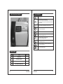
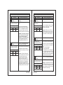
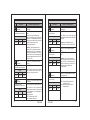
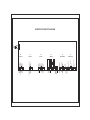
COLD ROOM CONTROLLER
USER MANUAL
INDIA
www.subzero.co
CRC-2052
Index
PARAMETER
Index
Pg.
No.
DESCRIPTION
PARAMETER
DESCRIPTION
Pg.
No.
Introduction
4
RH
To enable or disable humidity sensing.
15
Get to Know Your Controller
Items Included.
Key Introduction
5
5
6
H2
To set allowable high humidity limit.
16
H3
To set allowable low humidity limit.
16
H4
16
Fault Messages.
7
To set differential (Hysterisis) for
humidity.
LED Indication.
8
H5
To set probe calibration for humidity.
17
Parameter List.
9
H6
17
SET POINT
To set the cut-out point of the controller.
9
To set time delay between relay restart
time for humidity.
QFS
To set the quick freeze set point.
9
QFD
To set quick freeze duration.
18
CSET
To set the Condenser set point.
9
CND3
To set condenser logic.
18
HSET
To set cut out point of the controller for
Humidity.
10
CND4
To set condenser differential.
18
CND5
To set condenser probe calibration.
19
End of set mode
10
CND6
To set condenser on delay time.
19
To set other parameter
10
CND7
19
P2
To set allowable high temperature limit.
10
To set condenser status at hot gas
defrost.
P3
To set allowable low temperature limit.
11
L1
To set Evaporator Fan stop temperature.
20
P4
To set the differential for compressor
restart.
To set probe calibration.
11
L2
To set Evaporator Restart Delay.
20
L3
20
L8
To set Evaporator Fan status at
compressor off.
To set Evaporator Fan differential.
To set Evaporator probe calibration.
To set Evaporator Fan status at Door
open condition.
To set Evap Fan status during defrost.
22
BUZ
To enable / disable buzzer.
22
AL
22
C-UL
This parameter is used to set power on
delay for alarm.
Under load limit for compressor current.
C-OL
Over load limit for compressor current.
23
D-UL
Under load limit for Heater / Solenoid.
23-24
EXIT
P5
P6
12
P7
To set time delay between relay restart
time.
To set duration of defrost.
P8
To set defrost frequency.
13
P9
To set power on defrost delay.
13
12-13
13
P10
To set type of defrost.
14
P11
To set drip time for defrost.
14
P12
To set type of computation for defrost
time.
P13
01
To set defrost stop temperature.
14-15
15
CRC-2052
L4
L5
L7
CRC-2052
21
21
21
23
02
Index
PARAMETER
Introduction
Pg.
No.
DESCRIPTION
D-OL
Over load limit for Heater/Solenoid.
24
C2
Current sensing delay.
24
D0
To enable or Disable HP sensing.
24
D1
To enable or disable LP sensing.
25
D2
Fault sensing logic.
25
D3
To set LP sensing delay.
25
D4
To set reset mode for HP fault.
26
E1
To set Compressor Relay status on
Probe Failure.
26
TON
To set On cycle at room probe fail.
26
TOFF
To set Off cycle at room probe fail.
27
E7
To set Display at defrosting.
27
E8
Defrost duration during Coil probe failure.
27
LD
To set time delay to switch off the light .
28
PDN
To activate Solenoid Valve relay.
28
PW
To change password.
28
CRH
To view Compressor run Hours.
29
CCRH
Clear Compressor Run Hours.
29
ID
To set Unit ID.
29
LP
To activate Keypad Lock.
29
PO
To enable/disable Power Switch.
30
PDIS
To set display at power OFF mode.
30
FS
To restore default settings of the
controller.
31
EP
End of programming.
31
Technical Data
32-33
Caution & Warranty
34-35
The CRC-2052 is single set point cold room controller. The
Sub-Zero CRC-2052 is aesthetically superior versions of
their predecessors.
Features:
The controller controls the defrost in the system based on
either an electrical heater where the compressor is stopped, or
at cycle inversion using warm gas where the compressor
keeps on working.
There are safety features which include shutting down the
system incase of a fault from a pressure control or similar
device.
A series of “safety controls” (delay at start-up, minimum disable
time, minimum time between activation) protects the
compressors from close starts. In case of probe error or
temperature alarm, the instrument signals the event through
acoustic signal and by closing the relay contact. By pressing
the mute key, the buzzer is silenced.
A number of parameters are displayed alphanumerically to set
up the instrument for each specific function.
Computer Connectivity over RS485 and Remote
monitoring(Optional).
Single Operation Quick Freeze Mode(Press QF Key for 2 sec),
set system in quick freeze mode which is time based for that
period new set point will be lower than running set point and
system will try to achieve that set point, after time period over
set point will be normal set point.
Suggested Connection Diagram
03
CRC-2052
CRC-2052
04
Key Introduction
Get to Know Your Controller
Used to enter in manual defrost and to stop defrost if
defrosting is ON.
PROBE
Used to increment/scroll in Program Mode.
When not in any mode if this key is pressed for 2 secs controller will
enter in display Probe mode where Condenser/Evap temperature &
RH can be viewed.
Used to come mute the buzzer/Alarm & to exit any mode.
Fault Log
Used to enter in fault log mode.
PROBE
Used to switch OFF/ON the controller.
Used to enter in quick freeze mode.
PRG
Used to decrement/scroll in Program mode.
Used to enter into the program mode.
Used to enter into the Set mode. Also used as enter key if controller
is in Set mode/program mode.
PRG
Amp
Used to enter in display Amp. mode where compressor and
defrost current can be viewed.
Used to switch OFF/ON the light.
Items included
05
NO.
ITEMS
QTY
1.
CONTROLLER
1
2.
NTC SENSOR 5 METER
3
3.
CATALOGUE
1
4.
8 X 38 SCREW WITH RAWL PLUG
4
CRC-2052
CRC-2052
06
Fault Messages :
Ht
High temperature alarm for Room means, room temperature is
equal or above the set value of P2 parameter.
Lt
Low temperature alarm for Room means, room temperature is
equal or below the set value of P3 parameter.
High humidity alarm means, humidity is equal or above the set
value of H2 parameter.
HH
LH
Low humidity alarm Means humidity is equal or above the set
value of H3 parameter.
PP
Room temperature fail means, Room sensor not connected or
out of range.
Messages
C
E
Mode
Discription
On
Off
Flashing
Comp. Relay On.
Comp. Relay Off.
Comp. Relay Timedelay.
On
Off
Cond. Relay On.
Cond. Relay Off.
On
Off
Flashing
Evap. Relay On.
Evap. Relay Off.
Evap. Relay Timedelay.
C-PP
Condenser temperature fail means, condenser sensor not
connected or out of range.
On
Off
Flashing
Defrost Relay On.
Defrost Relay Off.
Defrost Relay Timedelay.
E-PP
Evaporator temperature fail means, Evaporator sensor not
connected or out of range.
On
Off
LSV Relay On.
LSV Relay Off.
H-PP
Humidity fail means, Humidity sensor not connected or out of
value.
On
Off
Alarm Relay On.
Alarm Relay Off.
SPPR
SPPR Fault.
Flashing
Controller is in drip time.
C-OL
Compressor over load fault.
C-UL
Compressor under load fault.
On
Off
Flashing
Humidifier On.
Humidifier Off.
Humidifier is in Timedelay.
D-OL
Defrost over load fault.
On
Off
Controller is in quick freeze mode.
Controller is not in quick freeze mode.
D-UL
Defrost under load fault.
Off
On
Power Off.
Power On.
HP
HP fault.
On
Off
Light Relay On.
Light Relay Off.
LP
LP fault.
R
On
Off
R-phase present.
R-phase absent.
Auxiliary fault.
Y
On
Off
Y-phase present.
Y-phase absent.
B
On
Off
B-phase present.
B-phase absent.
Emergency
Stop
On
Off
Controller is in emergency stop mode.
Controller is not in emergency stop
mode.
AUX
07
LED Indication
CRC-2052
CRC-2052
08
Description of parameters and functions.
Min: MINIMUM Max : MAXIMUM
Fact. Set : FACTORY SETTING(DEFAULT)
Description of parameters and functions.
Sr.
No.
Parameter
Parameter setting method
04
Press & hold SET key for
2 seconds
SP
Range
Min
Max
H3+1%
H2-1%
05
QFS
Example : If this parameter is set to 70
then humidifier will be off at this
Fact. Set humidity .
70%
End of set mode
EXIT
To set other parameter
Press & hold PRG key for
2 seconds
PRG
Display will show ‘P2’ and scroll the
description of the parameter.
To go to other parameters ,
use up / down keys.
To set the quick freeze set point.
To change QFS parameter,
press the set key.
Range
Min
Max
-50.0ºC
SP
Use UP/DOWN keys to set desired value.
If controller is in quick freeze mode then
compressor will cut in/ cut out as per this
set point till the quick freeze duration is
Fact. Set over.
-5.0ºC
SP : Set Point.
CSET
To set the Condenser set point.
To change CSET parameter,
press the set key.
01
Min
Max
Fact. Set
0.0ºC
99.9ºC
20.0ºC
Function : To set allowable high
temperature limit.
P2
Parameter
To change P2 parameter,
press the set key.
Range
Min
Max
SP+0.5ºC
50.0ºC
Use UP/DOWN keys to set desired value.
If condenser logic is set to SP then
condenser will switch off at this set point.
Range
09
Function : To set cut out point of the
controller for Humidity.
Use UP/DOWN keys to set desired value.
To set the cut-out point of the controller.
To change Set Point parameter, Display will change to set value.
The set point value can now be changed
press the set key.
by using the UP/DOWN key. After
desired value, press the SET key & you
Range
will see “--” which confirms that the set
Min
Max
Fact. Set point has been stored in memory.
0ºC
P2-0.5ºC
QFS
03
Parameter setting method
HSET
Display will show ‘SET’ and scroll the
description of the parameter.
To go to other parameters,
use up / down keys.
02
Parameter
To change EXIT parameter,
press the set key.
To set other parameter
01
Sr.
No.
Use UP/DOWN key to set desired value.
Once set at a particular value, this will
not allow the set point to go above this
value and below P3 setting.
: Setting this parameter
Fact. Set Example
at 30.00C will not allow the set point to go
50.0ºC above 30.00C also if the temperature
reaches 30.00C, the display will show HT
(High Temperature). The alarm will be
ON. But at power on till the AL delay is
over controller will not generate HT Alarm.
HT
(Message on Display)
CRC-2052
CRC-2052
10
Description of parameters and functions.
Sr.
No.
02
Parameter
P3
Parameter
Function : To set allowable low
temperature limit.
To change P3 parameter,
press the set key.
Range
Min
-50.0ºC
Max
SP-0.5ºC
-50.0ºC
LT
To change P4 parameter,
press the set key.
Min
Max
0.5ºC
20.0ºC
11
Example : Setting this parameter at
-30.00C will not allow the set point to go
below -30.00C also if the temperature
reaches -30.00C, the display will show
LT (Low Temperature). The alarm will be
ON.
Function : To set the differential for
compressor restart.
P4
Parameter
Range
Use UP/DOWN key to set desired value.
Once set at a particular value, this will
not allow the set point to go below this
value and above P2 setting.
Fact. Set
(Message on Display)
03
Parameter setting method
Use UP/DOWN keys to set desired value.
Example(Cooling Mode) : If the set
point is set at 10.00C and differential is
Fact. Set set at 2.00C, then when the system
reaches 10.00C, the comp. relay will
2.0ºC
cutout. Since the differential is 2.00C, the
comp. Relay will cutin at 12.00C
(10.00C + 2.00C).
Description of parameters and functions.
Sr.
No.
Parameter setting method
Parameter
P5
Parameter
To change P5 parameter,
press the set key.
04
Range
Min
Max
-10.0ºC
10.0ºC
Function : To set probe calibration.
Use UP/DOWN keys to set desired
value. In time it may be possible that the
display may be offset by a degree or so.
To compensate for this error, you may
Fact. Set need to add or minus the degrees
required to achieve the correct
0.0ºC
temperature.
Example : The temperature on the
display is 28.0OC, whereas the actual
temperature is 30.0OC. You will need to
set this parameter to 2.0OC, which
means that once out of the programming
parameter, the display will show the
temperature 30.0OC (28.0OC + 2.0OC).
P6
Parameter
To change P6 parameter,
press the set key.
05
Range
Min
Max
Fact. Set
1 Min
20 Min
3 Min
Function : To set time delay between
relay restart time.
Use UP/DOWN keys to set desired value.
This parameter is used to protect the fan
from restarting in a short period of time
and can be set between 0 to 20 minutes.
Example : If this parameter is set at 3
minutes, the compressor will cut off at
the set temperature, but will not restart
for a minimum of 3 minutes, even if the
differential is achieved earlier. This
parameter is good to protect the life of
the compressor when there are power
fluctuations and the compressor is
switched off and on within a few seconds.
12
Description of parameters and functions.
Sr.
No.
06
Parameter
P7
Parameter
Parameter setting method
Function : To set duration of defrost.
To change the P7 Parameter
parameter, press the set key.
Range
Min
Max
Fact. Set
0 Min
99 Min
30 Min
Use UP/DOWN keys to set desired value.
This is maximum amount of time allowed
for defrost. If set to 0, there will be no
defrost cycle.
Example : If P7 is set to 15 Mins and
P8 parameter is set to 1 Hr. then after
every 1 Hr defrosting will take place for
15 mins.
Description of parameters and functions.
Sr.
No.
09
Parameter setting method
Parameter
P10
Parameter
Function : To set type of defrost.
To change the P10 Parameter
parameter, press the set key.
Range
Min
Max
HTR
HTG
10
Use UP/DOWN keys to set desired value.
HTR : Heater defrost where compressor
is OFF.
HTG : Hot Gas defrost where compressor
Fact. Set
is ON.
HTR
P11
Parameter
Function : To set drip time for defrost.
Use UP/DOWN keys to set desired value.
During this period Compressor,
Evaporator Fan, LSV relay and Heater
will stay off so that the defrost water can
Fact. Set drain out.
1 Min
To change the P11 Parameter
parameter, press the set key.
07
P8
Parameter
Function : To set defrost frequency.
To change the P8 Parameter
parameter, press the set key.
Range
Min
Max
1 Hr
31 Hrs
Use UP/DOWN keys to set desired value.
This is the amount of time between two
defrost cycles.
Fact. Set Example : same as P7 parameter.
6 Hr
Range
Min
Max
0 Min
30 Min
11
P12
Parameter
Function : To set type of computation for
defrost time..
To change the P9 Parameter
parameter, press the set key.
08
P9
Parameter
To change the P9 Parameter
parameter, press the set key.
Range
Min
Max
Fact. Set
0 Min
99 Min
30 Min
13
Range
Function : To set power on defrost delay.
Use UP/DOWN keys to set desired value.
This is the amount of time at power on
after which defrosting will take place
once.
Min
Max
REAL
CRH
Example : If P9 parameter is 30 mins
then at power after 30 mins defrosting
will take place once.
CRC-2052
CRC-2052
Use UP/DOWN keys to set desired value.
REAL = Total of real time.
Example : This means that the time
calculation for defrost frequency will be
Fact. Set for the total hours the unit has been
REAL running.
CRH - Sum of total compressor
operating times. This means that for
time calculation, the unit will add the
total time the compressor has been in
an ON mode.
It keeps a record of the hours worked
+/-½ Hour incase of a power failure.
14
Description of parameters and functions.
Sr.
No.
Parameter
Description of parameters and functions.
Parameter setting method
Sr.
No.
Example : If Defrost frequency is set to
6hrs. and 3.45 hrs have passed after
unit has started and power fails, then
defrost cycle will stat after 3½ hours
when power resumes.
14
Parameter setting method
Parameter
H2
Parameter
Function : To set allowable high humidity
limit.
To change the H2 Parameter
parameter, press the set key.
Range
12
P13
Parameter
Function : To set defrost stop
temperature
To change the P13 Parameter
parameter, press the set key.
Range
Min
Max
-50.0ºC
50.0ºC
Use UP/DOWN keys to set desired value.
Min
Max
Fact. Set
Hset+1
100%
100%
If coil/Evap temperature is reached upto
this temperature defrost will stop.
Fact. Set Example : If this parameter is set to
7.0ºC,then if defrosting is in progress then
4.0ºC when temperature reaches 7.0ºC, the
defrost process will stop.
HH
(Message on Display)
15
H3
Parameter
RH
Parameter
To change the RH Parameter
parameter, press the set key.
Range
Min
Max
Fact. Set
DIS
ENB
DIS
Range
Function : To enable or disable humidity
sensing.
Min
Max
Fact. Set
Use UP/DOWN keys to set desired value.
0%
Hset-1
0%
DISABLE : Humidity sensing disable.
ENABLE : Humidity sensing enable.
LH
(Message on Display)
16
H4
Parameter
15
CRC-2052
Min
Max
1%
10%
CRC-2052
Example : Setting this parameter at 70%
will not allow the set point of Humidity to
go above 70% .
Also, if the humidity reaches 70% or
above. the display will show HH(High
Humidity) indicating that the humidity has
gone above the value in this parameter
Use UP/DOWN keys to set desired value.
Once set at a particular value, this will not
allow the set point for Humidity to go
below this value and above H2 Set value.
Example : Setting this parameter at 40%
will not allow the set point of Humidity to
go below 40% .
Also, if the humidity reaches 40%. the
display will show LH(Low Humidity)
indicating that the humidity has gone
below the value in this parameter.
Function : To set differential (Hysterisis)
for humidity.
To change the H4 Parameter
parameter, press the set key.
Range
Once set at a particular value, this will not
allow the set point for Humidity to go
above this value and below H3 Set value.
Function : To set allowable low humidity
limit.
To change the H3 Parameter
parameter, press the set key.
13
Use UP/DOWN keys to set desired value.
Use UP/DOWN keys to set desired value.
Example : If the set point is set at 60%
and differential is set at 3, then when the
Fact. Set system reaches 60%, the Relay will cut
out. Since the differential is 3, the relay will
2%
cut in (restart) at 63% (60% -3%).
16
Description of parameters and functions.
Sr.
No.
17
Parameter setting method
Parameter
H5
Parameter
Function : To set probe calibration for
humidity.
To change the H5 Parameter
parameter, press the set key.
Range
Min
Max
-10%
10%
Use UP/DOWN keys to set desired
value.
In time it may be possible that the
Fact. Set display for Humidity may be offset by a
% or so. To compensate for this error,
0%
you may need to add or minus the %
required to achieve the correct Humidity.
Example : The Humidity on the display
is 40%, whereas the actual Humidity is
42%. You will need to set the H5
parameter to 2, which means that once
out of the programming mode, the
Humidity will show 42%(40% + 2%).
18
H6
Parameter
Function : To set time delay between
relay restart time for humidity.
To change the H6 Parameter
parameter, press the set key.
Range
Min
Max
1 Min
20 Min
17
Use UP/DOWN keys to set desired value.
This parameter is used to protect the
Humidifier from restarting in a short period
Fact. Set of time.
2 Min
Example : If H6 set at 3 minutes, the
relay for Humidifier will cut off at the set
Humidity, but will not restart for a
minimum of 3 minutes, even if the
differential is achieved earlier. This
parameter is good to protect the life of
the Humidifier or even in applications
where the probe is placed at places
where there are sudden & short changes
in humidity like above a cold room door.
CRC-2052
Description of parameters and functions.
Sr.
No.
19
Parameter setting method
Parameter
QFD
Parameter
Function : To set quick freeze duration.
To change the QFD Parameter, Use UP/DOWN keys to set desired value.
press the set key.
This is the maximum amount of time
Range
allowed for Quick Freeze. If set to “0”,
Min
Max
Fact. Set there will be no quick freeze.
0 Hr
20
12 Hrs
2 Hr
CND3
Parameter
Function : To set condenser logic.
To change the CND3
parameter, press the set key.
Range
Min
Max
COMP
SP
21
Function : To set condenser differential.
To change the CND4
parameter, press the set key.
Min
Max
0.5ºC
20.0ºC
CRC-2052
Use UP/DOWN keys to set desired value.
This function is used to set condenser
logic as per compressor or condenser Set
Fact. Set point
COMP = As per compressor.
COMP SP = As per condenser SP.
If this parameter is set to Compressor
then condenser will switch ON / OFF as
per compressor. But if set to SP then
Condenser will be OFF when condenser
temperature reaches condenser SP.
CND4
Parameter
Range
Example : If QFS is set to -20.0 C, and
quick freeze duration is set to 1 hr ,then
when it is in quick freeze mode, then the
Comp. will work on -20.0C set point for
1hr.
Use UP/DOWN keys to set desired value.
Example : If this parameter is set to SP
and CSET (Condenser set point ) is 20.0
Fact. Set deg & CND4 to 2.0 deg then at 20.0
degree condenser relay will be off and
2.0ºC restart at (20.0 +2.0) 22.0 deg
18
Description of parameters and functions.
Sr.
No.
22
Parameter
CND5
Parameter
Parameter setting method
Sr.
No.
Function : To set condenser probe
calibration.
25
To change the CND5
parameter, press the set key.
Range
Min
Max
-10.0ºC
10.0ºC
Use UP/DOWN keys to set desired
value.
In time it may be possible that the
display for condenser may be offset by a
Fact. Set deg or so. To compensate for this error,
you may need to add or minus the offset
0.0ºC required to achieve the correct
condenser temperature.
Example : The temperature on the
display is 28.0ºC, whereas the actual
temperature is 30.0ºC. You will need to
set the CND5 parameter to 2.0ºC, which
means that once out of the programming
mode, the temperature will show 30.0ºC
(28.0ºC+ 2.0ºC).
23
CND6
Parameter
Function : To set condenser on delay
timings.
To change the CND6
parameter, press the set key.
Range
Min
Max
0 Sec
30 Sec
24
19
Min
Max
OFF
ON
Range
Min
Max
-50.0ºC
50.0ºC
26
Use UP/DOWN keys to set desired value.
This function is used to decide the
condenser status when hot gas defrost is
Fact. Set on. This parameter is not applicable for
Heater defrost.
OFF
At hot gas defrost,
OFF : Condenser will be OFF
ON : Condenser will be ON
CRC-2052
Function : To set Evaporator Fan stop
temperature.
2.0ºC
L2
Parameter
Range
Min
Max
0 Min
20 Min
Max
OFF
ON
CRC-2052
Use UP/DOWN keys to set desired
value.
Example : If this is set at 3 minutes,
Fact. Set Evap. Fan relay will cut off at the set by
Evap. Fan Stop TC. Parameter but the
1 Min
Fan will not come on for a minimum of 3
minutes even if it’s differential is
achieved earlier.
Function : To set Evaporator Fan status
at compressor off.
To change the L3 parameter,
press the set key.
Min
Example : If this parameter is set to
2.0ºC, then Evap. Fan will cut off at 2.0ºC.
Function : To set Evaporator Restart
Delay.
L3
Parameter
Range
Use UP/DOWN keys to set desired value.
This setting is used to limit the max.
temperature beyond which the Evap.Fan
Fact. Set will cut off.
To change the L2 parameter,
press the set key.
27
Function : To set condenser status at hot
gas defrost.
To change the CND7
parameter, press the set key.
L1
Parameter
Use UP/DOWN keys to set desired value.
15 Sec
Parameter setting method
Parameter
To change the L1 parameter,
press the set key.
When Compressor delay over Condenser
Fan will come ON first, after cond. On
Fact. Set delay over Comp will come ON.
CND7
Parameter
Range
Description of parameters and functions.
Use UP/DOWN keys to set desired value.
OFF : Evaporator Fan will be Off at
compressor OFF.
Fact. Set ON : Evaporator Fan will be On at
compressor OFF.
ON
20
Description of parameters and functions.
Sr.
No.
28
Parameter
L4
Parameter
Function : To set Evaporator Fan
differential.
To change the L4 parameter,
press the set key.
Range
Min
Max
0.5ºC
20.0ºC
29
Function : To set Evaporator probe
calibration.
To change the L5 parameter,
press the set key.
Min
Max
-10.0ºC
10.0ºC
30
Function : To set CompressorEvaporator Fan status at Door open
condition.
To change the L7 parameter,
press the set key.
Min
Max
NORM
F-C
21
Use UP/DOWN keys to set desired value.
In time it may be possible that the display
may be offset by a degree or so. To
Fact. Set compensate for this error, you may need
to add or minus the degrees required to
0.0ºC achieve the correct temperature. Setting
value is from -10ºC to + 10ºC.
L7
Parameter
Range
Use UP/DOWN keys to set desired
value.
Example : If Evaporator Fan Stop Tc
Fact. Set parameteris set to 2.0ºC, and if EVAP
DIFFERENTIAL parameter is set to
2.0ºC 2.0ºC,then Evap. Fan will cut off at 2.0ºC
and restart only at 0.0ºC.
(2.0ºC-2.0ºC = 0.0ºC).
L5
Parameter
Range
Parameter setting method
Use UP/DOWN keys to set desired value.
At Door Open,
NORM : Normal.
Fact. Set FAN : Evaporator Fan Off.
COMP : Compressor Off.
NORM F-C
: Compressor and Evaporator Fan
Off.
CRC-2052
Description of parameters and functions.
Sr.
No.
31
Parameter setting method
Parameter
L8
Parameter
Function : To set Evaporator Fan status
during defrost.
To change the L8 Parameter
parameter, press the set key.
Range
Min
Max
OFF
ON
32
OFF : Evaporator Fan Off during
defrost.
Fact. Set ON : Evaporator Fan On during
defrost.
OFF
BUZ
Parameter
Function : To enable / disable buzzer.
To change the BUZ Parameter
parameter, press the set key.
Range
Min
Max
DIS
ENB
33
ENB
Function : This parameter is used to set
power on delay for alarm.
To change the AL Parameter
parameter, press the set key.
Range
Min
Max
99 Min
CRC-2052
Use UP/DOWN keys to set desired value.
Example:
ENB : Buzzer enabled.
Fact. Set DIS : Buzzer disabled.
AL
Parameter
0 Min
Use UP/DOWN keys to set desired value.
Use UP/DOWN keys to set desired value.
Example : If you set this parameter to
20, once the power is switched on, the
Fact. Set alarm will not activate for 20 minutes
after the power is switched on. This
30 Min is most useful to avoid the nuisance
alarms when the ambients are high
when the machine is switched on after
a long time.
22
Description of parameters and functions.
Sr.
No.
34
Parameter
C-UL
Parameter
Parameter setting method
Description of parameters and functions.
Sr.
No.
Parameter setting method
Parameter
controller will trip the Heater/Solenoid on
fault and activate respective alarm relay.
Also display will flash ‘D-UL’. Controller
will go in manual reset mode.
Function : Under load limit for
compressor current.
To change the C-UL parameter, Use UP/DOWN keys to set desired
press the set key.
value.
Range
Min
Max
0.0A
(C-OL
-1.0)A
35
C-OL
Parameter
Example : If C-UL= 1.0A and
Fact. Set compressor current is less than 1.0A
then and exists till C2 current sensing
1.0A
delay then it is registered as UL fault.
Compressor will get OFF on this fault. If
after 3 retries within 1 Hour current
drawn is still less than 1.0Amp the
controller will trip the compressor on
fault and activate respective alarm relay.
Also display will flash ‘C-UL’. Controller
will go in manual reset mode.
Function : Over load limit for compressor
current.
To change the C-OL parameter, Use UP/DOWN keys to set desired value.
press the set key.
Example : If C-OL= 10 A and compressor
Range
current is greater than 10 A then and exist
Min
Max
Fact. Set till C2 current sensing delay then C-OL
fault exists and flash on display.
(C-UL
18.0A
10.0A Compressor will be tripped on this fault.
+1.0) A
36
D-UL
Parameter
Function : Under load limit for Heater /
Solenoid.
To change the D-UL parameter, Use UP/DOWN keys to set desired
press the set key.
value.
Range
23
Min
Max
0.0A
(D-OL
-1.0) A
Example : If D-UL= 1.0A and Heater /
Fact. Set Solenoid current is less than 1.0A then
and exists till C2 current sensing delay
1.0A
then it is registered as UL fault. Heater /
Solenoid will get OFF on this fault. If
after 3 retries within 1 Hour current
drawn is still less than 1.0Amp the
CRC-2052
37
D-OL
Parameter
Function : Over load limit for
Heater/Solenoid.
To change the D-OL parameter, Use UP/DOWN keys to set desired
press the set key.
value.
Range
Min
Max
(D-UL
+1.0) A
18.0A
38
Example : If D-OL= 10 A and Heater /
Fact. Set Solenoid current is greater than 10 A
then and exist till C2 current sensing
10.0A delay then D-OL fault exists and flash on
display. Heater / Solenoid will be tripped
on this fault.
Function : Current sensing delay.
C2
Parameter
To change the C2 parameter,
press the set key.
Range
Min
Max
5 Sec
60 Sec
39
Example : If C2 = 5 sec then, any
current fault will be valid only when it
Fact. Set exists for more than 5 sec.
5 Sec
Function : To enable or Disable HP
sensing.
D0
Parameter
To change the D0 parameter,
press the set key.
Max
DIS
ENB
CRC-2052
Use UP/DOWN keys to set desired value.
Example :
Range
Min
Use UP/DOWN keys to set desired value.
If this parameter is set to
Fact. Set ENB : HP sensing is enabled.
DIS : HP sensing is disabled
ENB
Setting this parameter to disable will
ignore HP fault for compressor. If this
parameter is set to Enable then controller
will detect HP trip.
24
Description of parameters and functions.
Sr.
No.
40
Parameter
D1
Parameter
To change D1
parameter, press the set key.
Range
Min
Max
DIS
ENB
Description of parameters and functions.
Parameter setting method
Sr.
No.
Function : To enable or disable LP
sensing.
43
Use UP/DOWN keys to set desired
value.
Example:
Fact. Set If this parameter is set to
ENB : LP sensing is enabled.
ENB
DIS : LP sensing is disabled.
Parameter
To change D4 parameter,
press the set key.
Range
Max
MAN
AUTO
Setting this parameter to disable will
ignore LP fault for compressor. If this
parameter is set to Enable then controller
will detect LP trip.
41
D2
Parameter
Function : Fault sensing logic.
To change D2 parameter,
press the set key.
Range
Min
Max
0V
230V
42
0v : 0V at HP/LP/AUX input will be
sensed as fault and trip the
Fact. Set
compressor.
230V
230V : 230V at HP/LP/AUX input will be
sensed as fault and trip the
compressor.
D3
Parameter
Function : To set LP sensing delay.
To change D3 parameter,
press the set key.
Range
Min
Max
0 Sec
180 Sec
25
Use UP/DOWN keys to set desired
value.
Use UP/DOWN keys to set desired value.
Example : If this parameter is set to 5
sec,then LP fault will be sensed only
Fact.
Fact. Set
Set when it present continuously for 5 Secs.
30 Sec
CRC-2052
Function : To set reset mode for HP fault.
D4
Parameter
Min
44
Function : To set Compressor Relay
status on Probe Failure.
To change E1 parameter,
press the set key.
Min
Max
ON
OFF
45
Function : To set On cycle at room
probe fail.
To change TON parameter,
press the set key.
Min
Max
1 Min
30 Min
CRC-2052
Use UP/DOWN keys to set desired
value.
When set to
ON : Relay will stay ON.
Fact.
Set CYC : Relay performs a duty cycle of
Fact. Set
as per TON & TOFF .
CYC
OFF : Relay will stay OFF.
TON
Parameter
Range
Use UP/DOWN keys to set desired
value.
MAN : Manual Mode.
Fact.
Fact. Set
Set AUTO : Auto mode.
AUTO If this parameter set to “MAN” mode HP
fault will be cleared only after pressing
reset key for 2 seconds.
If this parameter is set to “AUTO” mode
HP fault will be cleared automatically
when it is healthy.
E1
Parameter
Range
Parameter setting method
Use UP/DOWN keys to set desired
value.
At room probe fail condition when E1
parameter is selected as 'CYC' then the
Fact.
Set
Fact. Set
on cycle is specified by Ton parameter.
10 Min
26
Description of parameters and functions.
Sr.
No.
46
Parameter
TOFF
Parameter
To change TON parameter,
press the set key.
Range
Min
Max
1 Min
30 Min
Range
Min
Max
TEMP
DEFR
Range
Min
Max
1 Min
10 Min
Sr.
No.
Function : To set Off cycle at room probe
fail.
48
Use UP/DOWN keys to set desired
value.
Parameter
LD
Parameter
To change LD parameter,
press the SET key.
Range
Min
Max
0 Min
30 Min
Use UP/DOWN keys to set desired
value.
This parameter is used set the time
Fact.
Fact. Set
Set delay to automatically switch off the light.
If LD is set to 0 then this parameter is
7 Min
disabled.
Example : If this parameter is set to 7
mins then, when light is switched on after
7 mins it will be switch off automatically.
Use UP/DOWN keys to set desired
value.
Function : Defrost duration during Coil
probe failure.
Use UP/DOWN keys to set desired
value.
Example: If this is set to 10 min,
Fact.
Fact. Set
Set then manual defrost for 10 min
will take place during Coil probe fail.
5 Min
PDN
Parameter
49
Function : To activate Solenoid Valve
relay.
To change PDN parameter,
press the set key.
Range
Min
Max
DIS
ENB
PW
Parameter
50
Range
CRC-2052
Min
Max
0
9999
CRC-2052
Use UP/DOWN keys to set desired
value.
DIS : SV relay will not activate.
ENB : SV relay will get activated and
Fact.
Set
Fact. Set
will cut out and cut-in according
to set temperature.
DIS
Function : To change password.
To change the PW parameter,
press the set key.
27
Parameter setting method
Function : To set time delay to switch off
the light .
Function : To set Display at defrosting.
TEMP : At defrosting temperature
Fact.
will be dispalyed.
Fact. Set
Set
DEFR : At Defrosting 'Defrost ON'
TEMP
will scroll.
E8
Parameter
To change E8 parameter,
press the SET key.
47
Parameter setting method
At room probe fail condition when E1
parameter is selected as 'CYC' then the
Fact.
Fact. Set
Set Off cycle is specified by Ton parameter.
4 Min
E7
47
Parameter
To change E7 parameter,
press the SET key.
Description of parameters and functions.
Use UP/DOWN key to change the
password.
User can enter into program mode
only if correct password is entered. If the
Fact.
Set password is wrong it will show ‘INVALID
Fact. Set
PASSWORD’.
0
28
Description of parameters and functions.
Sr.
No.
Parameter setting method
Parameter
Function : To view Compressor run
Hours.
CRH
Parameter
51
It will display compressor run hours. It's
a read only parameter.
Description of parameters and functions.
Sr.
No.
Parameter
PO
Parameter
To change PO parameter,
press the SET key.
23
55
Range
CCRH
52
Function : Clear Compressor Run
Hours.
Min
Max
Fact.
Fact. Set
Set
NO
YES
NO
To change Unit ID
parameter, press the SET key.
1
240
ENB
LP
To change Keypad Lock
parameter, press the set key.
Range
29
Min
Max
NO
YES
DIS : Disable power switch
Fact.
Fact. Set
Set ENB : Enables power switch
DIS
Controller has power switch, which
if enable puts controller in active or
stand by state.
If press for 2 seconds controller will
go in stand by mode, display will
be as per “PDIS” parameter.
To again switch to ACTIVE WORKING
MODE, press power switch again for 2
seconds. All leds and display will flash
and enter into NORMAL WORKING
MODE.
PDIS
Parameter
To change PDIS parameter,
press the SET key.
23
56
Fact.
Fact. Set
Set
1
Range
54
Function : To enable/disable Power
Switch.
Use UP/DOWN keys to get desired
value & press SET key to confirm.
This parameter is used to set the Unit ID
of the device.
Range
Max
DIS
Function : To set Unit ID.
ID
Parameter
Min
Max
If this parameter is set to ‘YES’
compressor run hours (CRH) are
cleared.
Range
53
Min
Parameter setting method
Function: To activate Keypad Lock.
Min
Max
This parameter can lock the keypad so
that tempering is not possible by bystanders.
LED
TEMP
Function : To set display at power OFF
mode.
Use UP/DOWN keys to set desired value.
At power OFF mode power OFF LED
will glow & display will be as below,
Fact.
Fact. Set
Set
LED : Display Will be Blank.
LED
OFF : Display will show OFF.
TEMP : Display will show Temperature.
NO : deactivates keypad lock.
Fact.
Fact. Set
Set YES : activates keypad lock.
NO
On activation, all the parameters can only
be viewed, but not modified.
If the keypad is locked “LOCK” message
will be displayed..
CRC-2052
CRC-2052
30
Description of parameters and functions.
Sr.
No.
Parameter
FS
Parameter
To change FS parameter,
press the SET key.
23
57
Range
Min
Max
NO
YES
58
Parameter setting method
Function : To restore default settings of
the controller.
Use UP/DOWN keys to set desired value.
When set to YES all parameters
are programmed to factory
Fact.
Fact. Set
Set values.
Useful to debug setting related
NO
problems.
EP
Parameter
To exit programming
parameter, press the SET key.
Function: To exit programming.
Once the set key is pressed, the
controller goes into the normal mode
and displays the Room Temperature and
all settings are recorded.
Technical Data
Housing
Dimensions
Mounting
Connection
: ABS Plastic.
: 400 x 300 x 135 mm
: Wall mounting.
: Spring clamp terminal block.
4 sq. mm wire.
Display
: 4 Digit, 1” Dot matrix Display and 14 LEDs for
indication.
Data Storage
: Non-Volatile EEPROM Memory.
Power Input (Options) : 415Vac +/-10%, 50-60Hz.
3Phase Supply with Neutral
Operating Temp
: 50C to 500C(non-condensing).
Storage temp
: -200C to 700C(non-condensing).
Output
:
Contactors Comp & Def. : 18A.
Contactor Evap.
: 9A.
Condenser Relay
: 10A/250Vac.
Light Relay
: 10A/250Vac.
Alarm Relay
: 5A/250Vac.
Humidifier Relay
: 10A/250Vac.
Sensors :
1) Temperature sensor:
Sensor Type
Resolution
Accuracy
Probe Tolerance at 250C
: NTC Thermistor.
: 0.10C.
: +/-10C.
: +/-0.30C.
Room & Evap Temperature :
Range
: -50.00C to 50.00C
Condenser Temperature :
Range
: 0.00C to 99.90C
2) Humidity sensor
Sensor Type
Range
Resolution
: 4-20mA out.
: 0 to 100%
: 1%.
Analog I/p:
Compressor current (R,Y,B)
Defrost current(R,Y,B)
Resolution
: 0.1Amp.
Accuracy
: +/-1 Amp.
31
CRC-2052
CRC-2052
32
Technical Data
Controller
Digital Inputs:
HP, LP, Auxillary, Door, Sppr, R-Ph, Y-Ph, B- Ph.
Buzzer
: Internal
RS485 Connectivity
: Modbus RTU Protocol
Baud Rate : 9600
Device ID : 1 (By Default)
Controller should be installed in a place protected by vibration, water and
corrosive gasses and where ambient temperature does not exceed the values
specified in the technical data.
Probe
To give a correct reading, the probe must be installed in a place protected from
thermal influences, which may affect the temperature to be controlled.
Caution
WIRING : The probe and its corresponding wires should never be installed
in a conduit next to control or power supply lines. The electrical wiring
should be done as shown in the diagram. The power supply circuit should
be connected to a protection switch.
WARNING : Improper wiring may cause irreparable damage and personal
injury. Kindly ensure that wiring is done by qualified personnel only.
Maintenance : Cleaning : Clean the surface of the controller with a soft
moist cloth. Do not use abrasive detergents, petrol, alcohol or solvents.
33
CRC-2052
CRC-2052
34
Notice
The information in this document is subject to change in order to improve
reliability, design or function without prior notice and does not represent a
commitment on the part of the company. In no event will the company be liable
for direct, indirect, special, incidental or consequential damage arising out of
the use or inability to use the product or documentation, even if advised of the
possibility of such damages. No part of this manual may be reproduced or
transmitted in any form or by any means without the prior written permission of
the company.
Disclaimer
This manual & its contents remain the sole property of A.S.Controls Pvt.Ltd.,
India and shall not be reproduced or distributed without authorization. Although
great care has been taken in the preparations of this document, the company
or its vendors in no event will be liable for direct, indirect, special, incidental or
consequential damage arising out of the use or inability to use the product or
documentation, even if advised of the possibility of such damages. No part of
this manual may be reproduced or transmitted in any form or by any means
without the prior written permission of the company. A.S.Controls Pvt.Ltd.
reserves the right to make and changes or improvements without prior notice.
OUR OTHER PRODUCTS
INDIA
Cold Room Controller
Chiller Controller
Two Compressors Controller
Heating Controller
Humidity Controller
Pressure Controller
TM
Warranty
This product is warranted against defects in materials and workmanship for a
period of one year from the date of purchase. During the warranty period,
product determined by us to be defective in form or function will be repaired or,
at our option, replaced at no charge. This warranty does not apply if the product
has been damaged by accident, abuse, and misuse or as a result of service or
modification other than by the company. This warranty is in lieu of any other
warranty expressed or implied. In no event shall the company be held liable for
incidental or consequential damages, such as lost revenue or lost business
opportunity arising from the purchase of this product.
35
CRC-2052
Ball Valves
Globe Valves
Hand Valves
Flow Switches
Solenoid Valves
00 / 13.03.12
GND
RH IN
CT5
CT6
GND
ALARM
HUMIDIFIER
LSV
R PHASE
COND
+
-
LP
AUX
B Phase
RS485
GND
NEUTRAL
R PHASE
Y Phase
HP
SPPR
DOOR
Room Probe
Coil Probe
Cond Probe
CT4
CT3
CT2
CT1
LIGHT
PHASE
DEF
COMP
EVAP
1
A1
2
EMERGENCY
STOP
SUGGESTED CONNECTION DIAGRAM
A2
A3
A4
A5
A6
A7
OUTPUTS
OUTPUTS
CT INPUT
SENSOR
FAULT SIGNALS
INPUT SUPPLY
6
5
4
4
3
8
7
6
5
14
13
12
11
10
9
8
10
9
8
7
6
12
11
10
9
8
7
3
2
1
2
1
4
3
2
1
7
6
5
4
3
2
1
5
4
3
2
1
6
5
4
3
2
1