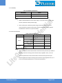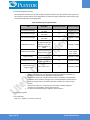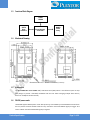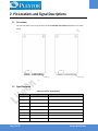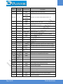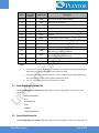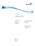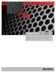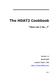
1
PX-xxG7Me
Model
PX-16G7Me
PX-32G7Me
mSATA (JEDEC MO-300)
SATA 6.0 Gb/s Solid State Drive
Product Specification
Manual Rev.:
Revision Date:
Rev1.0
2014/4/21
LITE-ON IT CORPORATION
Document History
Revision
Date
Rev 0.1
Rev 1.0
2013/12/24
2014/4/21
Page 2 of 26
Changes
First Release(Draft)
Change V1.0
Prodcut Specification
Copyright 2013 LITE-ON IT CORPORATION
Disclaimer
The information in this document is subject to change without prior notice in order to improve
reliability, design, and function and does not represent a commitment on the part of the
manufacturer. In no event will the manufacturer be liable for direct, indirect, special, incidental,
or consequential damages arising out of the use or inability to use the product or documentation,
even if advised of the possibility of such damages.
This document contains proprietary information protected by copyright.
All rights are reserved. No part of this datasheet may be reproduced by any mechanical,
electronic, or other means in any form without prior written permission of LITEON IT Corporation.
Product Specification
Page 3 of 26
Table of Contents
1
Introduction ........................................................................ 5
1.1
1.2
1.3
1.4
1.5
1.6
Overview : ................................................................................................. 5
Product Specification..................................................................................... 5
Functional Block Diagram ............................................................................. 11
Mechanical Drawing: ................................................................................... 11
Architecture.............................................................................................. 11
DEVSLP power mode.................................................................................. 11
2
Pin Locations and Signal Descriptions ...................................... 12
2.1
2.2
Pin Locations ............................................................................................ 12
Signal Descriptions ..................................................................................... 12
3
ATA Command Sets............................................................. 15
3.1
3.2
3.3
3.4
3.5
3.6
ATA Command ......................................................................................... 15
Power Management Command Set ................................................................. 19
Security Mode Feature Set ............................................................................ 19
SMART Command Set ................................................................................ 20
Host Protected Area Command Set ................................................................. 21
48-Bit Address Command Set ........................................................................ 21
3.7
3.8
Device Configuration Overlay Command Set ...................................................... 22
General Purpose log Command Set ................................................................. 22
4
SATA Command Sets ........................................................... 23
4.1
SATA Command ........................................................................................ 23
5
References ........................................................................ 24
6
Terms and Acronyms ........................................................... 25
Page 4 of 26
Prodcut Specification
1 Introduction
1.1
Overview :
The PX-xxG7Me MLC series mSATA 6 Gb/s Solid State Drive (mSATA SSD) delivers leading performance in an
industry standard JEDEC MO-300 form factor while simultaneously improving system responsiveness for mobile
applications over standard rotating drive media or hard disk drives. By combining leading NAND flash memory
technology with our innovative high performance firmware, LITEON IT delivers a SSD for native Serial Advanced
Technology Attachment (SATA) hard disk drive drop-in replacement with enhanced performance, reliability,
ruggedness and power savings. Since there are no rotating platters, moving heads, fragile actuators, or
unnecessary delays due to spin-up time or positional seek time that can slow down the storage subsystem,
significant I/O and throughput performance improvement is achieved as compared to rotating media or hard
disk drives. This document describes the specifications of the PX-xxG7Me MLC series mSATA SSD in JEDEC MO300 form factors.
The PX-xxG7Me mSATA SSD primarily targets mSATA based laptop PCs, highly rugged mobile client devices, as
well as thin and light mini/sub-notebooks. Key attributes include high performance, low power, increased
system responsiveness, high reliability, and enhanced ruggedness as compared to standard mobile mSATA hard
drives. The PX-xxG7Me mSATA SSD is available in JEDEC MO-300 form factor that are electrically, mechanically,
and software compatible with existing JEDEC MO-300 Serial ATA slots. Our flexible design allows
interchangeability with existing mobile hard drives based on the mSATA interface standard.
1.2
Product Specification
1.2.1. Form Factor: JEDEC MO-300 mSATA SSD form factor
1.2.2. Capacity: available now
16GB (PX-16G7Me)
32GB (PX-32G7Me)
Table 1 User Addressable Sectors
Unformatted capacity
Total user addressable sectors
in LBA mode
16GB
31,277,232
32GB
62,533,296
Notes: 1. 1GB=1,000,000,000 bytes and not all of the memory can be used for storage.
2. 1 Sector = 512 bytes
1.2.3. Flash: Multi-Level Cell (MLC) component with Toggle-Mode
Product Specification
Page 5 of 26
1.2.4. Band Performance
Table 2 Maximum Sustained Read and Write Bandwidth
Capacity
16 GB
32 GB
Access Type
MB/s
Sequential Read
Up to 270 MB/s ( SATA 6Gb/s )
Sequential Write
Up to 40 MB/s ( SATA 6Gb/s )
ATTO up to Read 270 MB/s, Write 40 MB/s
Sequential Read
Up to 530 ( SATA 6Gb/s )
Sequential Write
Up to 80 ( SATA 6Gb/s )
ATTO up to Read 540 MB/s, Write 80 MB/s
Notes: 1). Performance measured using CrystalDiskMark. ATTO
2). 1 MB/sec = 1,048,576 bytes/sec is used in measuring sequential performance.
If 1 MB/sec = 1,000,000 bytes/sec is used, performance values become 4.85% higher.
3). Test platform: ASUS P8Z68-V Pro Gen3 (Windows 7 x64)
4). Test by secondary drive(data drive)
1.2.5. Read and Write IOPS (IOMETER)
Table 3 Random Read/Write Input/Output Operations per Second
Capacity
16GB
Access Type
IOPS
4K Read (IOPS)
4K Write (IOPS)
27,000 (SATA 6Gb/s)
8,000 (SATA 6Gb/s)
CDM QD32 IOPS up to Read 29,000, Write 10,000
32GB
4K Read (IOPS)
4K Write (IOPS)
55,000 (SATA 6Gb/s)
20,000 (SATA 6Gb/s)
CDM QD32 IOPS up to Read 57,000, Write 21,000
Notes: 1. Performance measured using IOMETER with queue depth set to 32, Crystal Disk Mark QD32.
2. Write cache enabled
3. Test computer: ASUS P8Z68-V Pro Gen3 (SATA 6 Gb/s – Win7 x64)
4. Test by secondary drive(data drive)
1.2.6. Ready Time
Table 4 Latency Specifications
Page 6 of 26
Type
Average Latency
Power on to Ready
Resume from DEVSLP
500ms
100ms
Prodcut Specification
Notes: 1. Write cache enabled
2. Device measured form power-on to ready to receive first Media command.
1.2.7. Compatibility
-- SATA Revision 3.0 compliant
Compatible with SATA 1.5Gb/s, 3.0Gb/s & 6.0Gb/s interface rates
-- ATA/ATAPI- 8 compliant
-- SSD enhanced SMART ATA feature set
-- Native Command Queuing (NCQ) command set
-- TRIM supported
1.2.8. Certifications
Table 5 Device Certifications
Certification
Description
CE compliant
Indicates conformity with the essential health and safety
requirements set out in European Directives Low voltage
Directive and EMC Directive
UL certified
Underwriters Laboratories, Inc. Component Recognition
UL60950-1
BSMI
Compliance to the Taiwan EMC standard “Limits and methods of
Radio Disturbance Characteristics of Information Technology
Equipment, CNS 13438 Class B”
Microsoft WHQL Microsoft Windows Hardware Quality Labs
RoHS compliant
Restriction of Hazardous Substance Directive
1.2.9. mSATA Interface Power Management
-- 3.3V SATA
-- SATA interface power management
Product Specification
Page 7 of 26
1.2.10. Power Consumption
Table 6 Operating Voltage
Capacity
Description
Min
Max
Unit
16GB
Operating voltage for 3.3V (+/- 5%)
3.135
3.465
V
32GB
Operating voltage for 3.3V (+/- 5%)
3.135
3.465
V
Table 7 Power Consumption (MobileMark)
Capacity
Mode
Max
Unit
16GB
DIPM Enable
0.2
W
32GB
DIPM Enable
0.2
W
Table 8 DEVSLP Mode Power Consumption
Capacity
Mode
Max
Unit
16GB
DEVSLP
3
mW
32GB
DEVSLP
3
mW
1.2.11. Temperature
Table 9 Temperature Relative Specifications
Environment
Mode
Min
Max
Unit
Ambient
Temperature
Operating
0
70
°C
Non-operating
-40
85
°C
Operation
5
95
%
Non-operation
5
95
%
Humidity
Note: Measured without condensation
Page 8 of 26
Prodcut Specification
1.2.12. Reliability
Table 10 Reliability specifications
Parameter
Value
Mean Time between Failure (MTBF)
> 1,500,000 hours
Power on/off cycles
50000 cycles
Notes:
MTBF is calculated based on a Part Stress Analysis. It assumes nominal voltage. With
1.
all other parameters within specified range.
Power on/off cycles is defined as power being removed from the drive, and the
2.
restored. Most host systems remove power from the drive when entering suspend
and hibernate as well as on a system shutdown.
1.2.13. Shock and Vibration
Table 11 Shock and Vibration
Item
Shock
1
Vibration
2
Mode
Timing/Frequency
Max
operating
At 1 msec half-sine
1500G
operating
At 2 msec half-sine
1000G
Non-operating
At 1 msec half-sine
1500G
Non-operating
At 2 msec half-sine
1000G
Operation
7~800 Hz
2.17Grms
Non-operation
7~800 Hz
3.08Grms
Notes:
1.
Shock specifications assume that the SSD is mounted securely with the input vibration
applied to the drive mounting screws. Stimulus may be applied in the X, Y or Z axis.
2.
Vibration specifications assume that the SSD is mounted securely with the input
vibration applied to the drive mounting screws. Stimulus may be applied in the X, Y or
Z axis. The measured specification is in root mean squared form.
Product Specification
Page 9 of 26
1.2.14. Electromagnetic Immunity
Electromagnetic Immunity tests assume the SSD is properly installed in the representative host system. The
drive operates properly without errors degradation in performance when subjected to radio frequency (RF)
environments defined in the following table.
Table 12 Radio Frequency Specifications
Test
Electrostatic discharge
Electrostatic discharge
Electrostatic discharge
Radiated RF immunity
Electrical fast transient
Description
Contact ±4KV
Air: ±8KV
Contact ±6KV
Air: ±12KV
Contact ±8KV
Air: ±15KV
80~1000MHz, 3V/m,
80% AM with 1 KHz sine
900 MHz, 3 V/m, 50%
pulse modulation at
200Hz
±1KV on AC mains
±0.5KV on external I/O
±1KV differential ±2KV
common, AC mains
150KHz~80 MHz, 3 Vrms,
Conducted RF immunity
80% AM with 1KHz sine
Surge immunity
Power frequency
magnetic field
50Hz, 1A/m (r.m.s.)
Performance criteria
Reference standard
A
IEC 61000-4-2:2008
B
IEC 61000-4-2:2008
C
IEC 61000-4-2:2008
A
IEC 61000-4-3:2008
B
IEC 61000-4-4:2004
+Corr.1:2006
+Corr.2:2007
B
IEC 61000-4-5:2005
A
IEC 61000-4-6:2008
A
IEC 61000-4-6:2008
Notes:
1. Performance criterion A = The device shall continue to operate as intended, i.e.,
normal unit operation with no degradation of performance.
2. Performance criterion B = The device shall continue to operate as intended after
completion of test, however, during the test, some degradation of performance is
allowed as long as there is no data loss operator intervention to restore device
function.
3. Performance criterion C = Temporary loss of function is allowed. Operator
intervention is acceptable to restore device function.
4. Contact electrostatic discharge is applied to drive enclosure.
1.2.15. Weight: 9 g Max.
1.2.16. Dimension:
50.8 mm x 29.85mm x 3.55 mm (L x W x H)
Page 10 of 26
Prodcut Specification
1.3
Functional Block Diagram
DDR3
DRAM
SATA
Host
Interface
1.4
Flash Memory
Controller
NAND
Flash
Array
Mechanical Drawing:
Dimension: 50.8 mm x 29.85mm x 3.55 mm (L x W x H)
1.5
Architecture
The PX-xxG7Me MLC series mSATA 6Gb/s Solid State Drive (SSD) utilizes a cost effective system-on-chip
(SoC) design to provide a full 6Gb/s bandwidth with the host while managing multiple flash memory
devices on multiple channels internally.
1.6
DEVSLP power mode
LiteON SSD support DEVSLP power mode. After power up, and enabled by a SET FEATURES command from
the host, device will enter DEVSLP mode from any state after receive HW DEVSLP signal pin trigger. And
return to Reset state after HW DEVSLP signal pin negated.
Product Specification
Page 11 of 26
2 Pin Locations and Signal Descriptions
2.1
Pin Locations
The data and power connector pin locations of the PX-xxG7Me series mSATA 6 Gb/s SSD are as shown
below.
2.2
Signal Descriptions
Table 13 Connector Pin Definitions
Page 12 of 26
Name
Type
Description
P1
Reserved
No Connect
P2
+3.3V
3.3V Power
P3
Reserved
No Connect
P4
GND
P5
Reserved
P6
+1.5V
P7
Reserved
No Connect
P8
Reserved
No Connect
Return Current Path
No Connect
1.5V Power ( No use )
Prodcut Specification
Name
Type
Description
P9
GND
Return Current Path
P10
Reserved
No Connect
P11
Reserved
No Connect
P12
Reserved
No Connect
P13
Reserved
No Connect
P14
Reserved
No Connect
P15
GND
P16
Reserved
No Connect
P17
Reserved
No Connect
P18
GND
P19
Reserved
No Connect
P20
Reserved
No Connect
P21
GND
P22
Reserved
P23
+B
P24
+3.3V
P25
-B
P26
GND
Return Current Path
P27
GND
Return Current Path
P28
+1.5V
1.5V Power ( No use )
P29
GND
Return Current Path
P30
Two Wire Interface
P31
-A
P32
Two Wire Interface
P33
+A
P34
GND
Return Current Path
P35
GND
Return Current Path
P36
Reserved
P37
GND
P38
Reserved
No Connect
P39
+3.3V
3.3V Power
P40
GND
Return Current Path
P41
+3.3V
3.3V Power
P42
Reserved
No Connect
Product Specification
Return Current Path
Return Current Path
Return Current Path
No Connect
Host Receiver Differential Signal Pair B
3.3V Power
Host Receiver Differential Signal Pair B
No Connect
Host Transmitter Differential Signal Pair A
No Connect
Host Transmitter Differential Signal Pair A
No Connect
Return Current Path
Page 13 of 26
Name
Type
Description
P43
Device Type
No Connect
P44
Device Sleep Signal
If system didn't support DEVSLP, set DEVSLP Sleep
Signal pin power high and keep (from power on),
device will ignore.
If system support DEVSLP, set DEVSLP Sleep Signal
pin power low (from power on) device, device will
support DEVSLP function.
Device Sleep Signal H: SSD enter sleep model.
Device Sleep Signal L: SSD exit sleep model.
Page 14 of 26
Vendor Specific / Manufacturing Pin/No connect on
the host side
P45
Vendor
P46
Reserved
P47
Vendor
P48
+1.5V
P49
DAS
Device Activity Signal
P50
GND
Return Current Path
P51
Presence Detection
P52
+3.3V
No Connect
Vendor Specific / Manufacturing Pin/No connect on
the host side
1.5V Power ( No use )
This pin connect 0 ohm resistor to GND to indicate
the presence of an mSATA device
3.3V Power
Prodcut Specification
3 ATA Command Sets
3.1
ATA Command
The PX-xxG7Me MLC series mSATA 6Gb/s SSD supports all the mandatory ATA commands defined in the
ATA/ATAPI-8 specification.
3.1.1 ATA General Feature Command Set
The PX-xxG7Me MLC series mSATA 6Gb/s SSD supports the ATA General feature Command set (nonpacket), which consists of
.EXECUTE DEVICE DIAGNOSTIC
.FLUSH CACHE
.IDENTIFY DEVICE
.READ DMA
.READ DMA WITHOUT RETRIES
.READ SECTOR(S)
.READ SECTORS(S) WITHOUT RETRIES
.READ VERIFY SECTORS(S)
.READ VERIFY SECTORS(S) WITHOUT RETRIES
.SEEK
.SET FEATURES
.WRITE DMA
.WRITE DMA WITHOUT RETRIES
.WRITE SECTOR(S)
.WRITE SECTOR(S) WITHOUT RETRY
.READ MULTIPLE
.SET MULTIPLE MODE
.WRITE MULTIPLE
.INITIALIZE DEVICE PARAMETERS
.DATA SET MANAGEMENT
The PX-xxG7Me MLC series mSATA 6Gb/s SSD supports all the following optional commands
.READ BUFFER
.WRITE BUFFER
.DOWNLOAD MICROCODE
Product Specification
Page 15 of 26
3.1.2 Identify Device Data
The following table details the sector data returned after issuing an IDENTIFY DEVICE command.
Table 14 Returned Sector Data
Word
F=Fixed
V=Variable
X=Both
Default Value
0
F
0040h
General configuration bit-significant information
1
F
3FFFh
Obsolete-Number of logical cylinders (16,383)
2
F
C837h
Specific configuration
3
F
0010h
Obsolete-Number of logical heads (16)
4-5
F
0000h
Retired
6
F
003Fh
Obsolete-Number of logical sectors per logical track (63)
7-8
F
0000h
Reserved for assignment by the Compact Flash Association
9
10-19
20-22
F
V
F
0000h
Var.
0000h
Retired
Serial number (20 ASCII characters)
Retired / Obsolete
23-26
V
Var.
Firmware revision (8 ASCII characters)
27-46
V
Var.
Model number
47
F
8010h
7:0 – Maximum number of sectors transferred per
interrupt on multiple commands
48
F
4000h
Trusted Computing feature set options, bit14 should be 1
49
F
2F00h
Capabilities
50
F
4000h
Capabilities
51-52
F
0000h
Obsolete
53
F
0007h
Words 88 and 70:64 valid
54
V
Var.
Obsolete - Number of logical cylinders (16,383)
55
V
Var.
Obsolete - Number of logical heads (16)
56
V
Var.
Obsolete - Number of logical sectors per logical track (63)
57-58
V
Var.
Capacity(Cylinders*heads*sectors)
59
V
01xxh
V
31,277,232
(16GB)
46,905,264
(24GB)
62,533,296
(32GB)
60-61
Page 16 of 26
Description
Number of sectors transferred per interrupt on multiple
commands(Bit7:0 are variable)
Total number of user addressable logical sectors for 28-bit
commands (DWord)
Prodcut Specification
Word
F=Fixed
V=Variable
X=Both
Default Value
62
F
0000h
Obsolete
63
V
0007h
Multi-word DMA modes supported/selected
64
F
0003h
PIO modes supported
65
F
0078h
Minimum multiword DMA transfer cycle time per word
66
F
0078h
Manufacture’s recommended multiword DMA transfer
cycle time
67
F
0078h
Minimum PIO transfer cycle time without flow control
68
F
0078h
Minimum PIO transfer cycle time with IORDY flow control
69-70
F
0000h
Reserved(for future command overlap and queuing)
71-74
F
0000h
Reserved for the IDENTIFY packet DEVICE command
75
F
001Fh
4:0 Maximum Queue depth-1=31
76
V
070Eh
Serial ATA capabilities
77
V
Var.
Reserved for Serial ATA
78
V
014Ch
79
V
Var.
80
F
01FEh
Major Version Number
81
F
0021h
Minor Version Number
82
F
346Bh
Commands and feature sets supported
83
F
7D01h
Commands and feature sets supported
84
F
4123h
Commands and feature sets supported
85
V
3469h
Commands and feature sets supported or enabled
86
V
BC01h
Commands and feature sets supported or enabled
87
F
4123h
Commands and feature sets supported or enabled
88
V
407Fh
Ultra DMA modes
89
F
0003h
Time required for security erase unit completion
90
F
0003h
Time required for enhanced security erase completion
91
F
0000h
Current advanced power management value
92
V
Var.
93
V
0000h
Hardware reset result. The contents of bits (12:0) of this
word shall change only during the execution of a hardware
reset.
94
F
0000h
Current AAM value
95
F
0000h
Stream Minimum Request Size
96
F
0000h
Streaming Transfer Time - DMA
97
F
0000h
Streaming Access Latency - DMA and PIO
Product Specification
Description
Serial ATA features supported
Serial ATA features enabled
Master Password Identifier
Page 17 of 26
Word
F=Fixed
V=Variable
X=Both
Default Value
98-99
F
0000h
100-103
V
31,277,232
(16GB)
46,905,264
(24GB)
62,533,296
(32GB)
104
F
0000h
Streaming Transfer Time - PIO
105
F
0008h
Maximum number of 512-byte blocks per DATA SET
MANAGEMENT command
106
F
4000h
Physical sector size/logical sector size
107
F
0000h
Inter-seek delay for ISO-7779 acoustic testing in
microseconds
108-111
V
0000h 0000h
0000h 0000h
112-115
F
0000h
Reserved for word wide name extension to 128 bits
116
F
0000h
Reserved for TLC
117-118
F
0000h
Words per logical sector
119
F
4010h
Commands and feature sets supported
120
F
4010h
Commands and feature sets supported or enabled
121-126
F
0000h
Reserved for expanded supported and enabled settings
127
F
0000h
Removable Media Status Notification feature set support
128
V
002xh
Security status (Bit4:1 are variable)
129-159
F
0000h
Vendor specific
160
F
0000h
Compact Flash Association (CFA) power mode 1
161-167
F
0000h
Reserved for the CompactFlash Association
168
F
0000h
169
F
0001h
170-173
V
Var.
174-175
F
0000h
Reserved
176-205
F
0000h
Current media serial number (ATA string)
206
F
003Dh
SCT Command Transport
207-208
F
0000h
Reserved
209
F
4000h
Alignment of logical blocks within a physical block
210-211
F
0000h
Write-Read-Verify Sector Count Mode 3 (DWord)
212-213
F
0000h
Write-Read-Verify Sector Count Mode 2 (DWord)
214
F
0000h
NV Cache Capabilities
Page 18 of 26
Description
Streaming Performance Granularity
Maximum user LBA for 48-bit Address feature set
World wide name
DATA SET MANAGEMENT command is supported
Additional Product Identifier (ATA String)
Prodcut Specification
Word
F=Fixed
V=Variable
X=Both
Default Value
215-216
F
0000h
NV Cache Size in Logical Blocks (DWord)
217
F
0001h
Nominal media rotation rate
218
F
0000h
Reserved
219
F
0000h
NV Cache Options
220
F
0000h
7:0 Write-Read-Verify feature set current mode
221
F
0000h
Reserved
222
F
1075F
Transport major version number
223
F
0000h
Transport minor version number
224-229
F
0000h
Reserved
230-233
F
0000h
Extended Number of User Addressable Sectors (QWord)
234
F
0000h
235
F
0000h
236-254
F
0000h
255
V
Var.
Description
Minimum number of 512-byte data blocks per DOWNLOAD
MICROCODE command for mode 03h
Minimum number of 512-byte data blocks per DOWNLOAD
MICROCODE command for mode 03h
Reserved
Integrity word
Notes:
1.
F=Fixed. The content of the word is fixed and does not change for removable media devices,
these values may change when media is Removed or changed.
2.
V=Variable. The state of at least one bit in a word is variable and may change depending on
the state of the device or the commands executed by the device.
3.
3.2
X=F or V. The content of the word may be fixed or variable.
Power Management Command Set
The PX-xxG7Me MLC series mSATA 6Gb/s SSD supports the power management command set, which
consists of
.CHECK POWER MODE
.IDLE
.IDLE IMMEDIATE
.SLEEP
.STANDBY
.STANDBY IMMEDIATE
3.3
Security Mode Feature Set
The PX-xxG7Me MLC series mSATA 6 Gb/s SSD supports the Security Mode command set, which consist of
Product Specification
Page 19 of 26
.SECURITY SET PASSWORD
.SECURITY UNLOCK
.SECURITY ERASE PREPARE
.SECURITY ERASE UNIT
.SECURITY FREEZE LOCK
.SECURITY DISABLE PASSWORD
3.4
SMART Command Set
The PX-xxG7Me MLC series mSATA SSD supports the SMART command set, which consist of
.SMART ENABLE OPERATIONS
.SMART DISABLE OPERATIONS
.SMART ENABLE/DISABLE AUTOSAVE
.SMART RETURN STATUS
The PX-xxG7Me MLC series mSATA 6Gb/s SSD supports the following optional commands.
.SMART EXECUTE OFF-LINE IMMEDIATE
.SMART READ DATA
.SMART READ LOG
.SMART WRITE LOG
The table below lists the SMART commands.
Table 15 SMART commands
Subcommand
SMART ATTRIBUTE VALUES (READ DATA)
D0h
READ ATTRIBUTE THRESHOLDS
D1h
ENABLE/DISABLE ATTRIBUTE AUTOSAVE
D2h
SAVE ATTRIBUTE VALUES
D3h
EXECUTE OFF-LINE IMMEDIATE
D4h
LBA Low value
EXECUTE SMART OFF-LINE ROUTINE
00h
EXECUTE SMART SHORT SELF-TEST ROUTINE (OFFLINE)
01h
EXECUTE SMART EXTENDED SELF-TEST ROUTINE (OFFLINE)
02h
ABORT OFF-LINE ROUTINE
7Fh
EXECUTE SMART SHORT SELF-TEST ROUTINE (CAPTIVE)
81h
EXECUTE SMART EXTENDED SELF-TEST ROUTINE ( CAPTIVE )
82h
READ LOG SECTOR
Page 20 of 26
Code
D5h
Prodcut Specification
3.5
WRITE LOG SECTOR
D6h
ENABLE SMART OPERATIONS
D8h
DISABLE SMART OPERATIONS
D9h
RETURN SMART STATUS
DAh
Enable/Disable Automatic OFFLINE
DBh
Host Protected Area Command Set
The PX-xxG7Me MLC series mSATA 6Gb/s SSD supports the Host Protected Area command set which
consists of
.READ NATIVE MAX ADDRESS
.SET MAX ADDRESS
.READ NATIVE MAX ADDRESS EXT
.SET MAX ADDRESS EXT
The PX-xxG7Me MLC series mSATA 6Gb/s SSD supports the following optional commands.
.SET MAX SET PASSWORD
.SET MAX LOCK
.SET MAX FREEZE LOCK
.SET MAX UNLOCK
3.6
48-Bit Address Command Set
The PX-xxG7Me MLC series mSATA 6Gb/s SSD supports the Host Protected Area command set, which
consists of
.FLUSH CACHE EXT
.READ DMA EXT
.READ NATIVE MAX ADDRESS EXT
.READ SECTOR(S) EXT
.READ VERIFY SECTOR(S) EXT
.READ MULTIPLE EXT
.SET MAX ADDRESS EXT
.WRITE DMA EXT
.WRITE MULTIPLE EXT
.WRITE MULTIPLE FUA EXT
.WRITE SECTOR(S) EXT
Product Specification
Page 21 of 26
3.7
Device Configuration Overlay Command Set
The PX-xxG7Me MLC series mSATA 6Gb/s SSD supports the Device configuration Overlay command set,
which consists of
.DEVICE CONFIGURATION FREEZE LOCK
.DEVICE CONFIGURATION IDENTITY
.DEVICE CONFIGURATION RESTORE
.DEVICE CONFIGURATION SET
3.8
General Purpose log Command Set
The PX-xxG7Me MLC series mSATA 6Gb/s SSD supports the general purpose log command set, which
consists of
.READ LOG EXT
.WRITE LOG EXT
Page 22 of 26
Prodcut Specification
4 SATA Command Sets
4.1
SATA Command
The SATA 3.0 Specification is a super set of the ATA/ATAPI-8 specification with regard to supported
commands. The PX-xxG7Me MLC series mSATA 6Gb/s SSD supports the following features which are
unique to the SATA 3.0 Specification.
4.1.1. Software Settings Preservation
The PX-xxG7Me MLC series mSATA 6Gb/s SSD supports the SET FEATURES parameter to enable/disable
the preservation of software settings.
4.1.2. Native Command Queuing
The PX-xxG7Me MLC series mSATA 6Gb/s SSD supports the Native Command Queuing (NCQ) command
set, which includes.
.READ FPDMA QUEUED
.WRITE FPDMA QUEUED
Note: with a maximum queue depth equal to 32
Product Specification
Page 23 of 26
5 References
This document references standards defined by a variety of organizations as listed below.
Table 16 Standards References
Date
Title
Location
Dec 2008
VCCI
http://www.vcci.or.jp/vcci_e/general/jo
in/index.html
July 2007
ROHS
Search for material description
datasheet at http://intel.pcnalert.com
July 2007
SFF-8144, 1.8” drive form factor
http://www.sffcommittee.org
February 2007
Serial ATA Revision 2.6
http://www.sata-io.org
May 2006
SFF-8223, 2.5” Drive w/Serial Attachment
Connector
http://www.sffcommittee.org
May 2005
SFF-8201, 2.5” drive form factor
http://www.sffcommittee.org
April 2004
ATA-7 Spec. Volume 1
http://www.t13.org/
Aug. 2009
ATA-8 Spec. Rev 2
http://www.t13.org/
International Electro Technical Commission
EB61000
Page 24 of 26
2008
4-2 Personnel Electrostatic Discharge Immunity
2008
4-3 Electromagnetic compatibility (EMC)
2004
4-4 Electromagnetic compatibility (EMC)
2005
4-5 Electromagnetic compatibility (EMC)
2008
4-6Electromagnetic compatibility (EMC)
2008
4-11 (Voltage variations)
2004
ENV 50204 (Radiated electromagnetic field
from digital radio telephones)
http://www.iec.ch
http://www.iec.ch
Prodcut Specification
6 Terms and Acronyms
This document incorporates many industry- and device-specific words use the following list to define a variety of
terms and acronyms.
Table 17 Glossary of Terms and Acronyms
Term
Definition
ATA
Advanced Technology Attachment
ATAPI
Advanced Technology Attachment Packet Interface
BER
Bit Error Rate, or percentage of bits that have errors relative to the total
number of bits received
BIOS
Basic Input/Output System
Chipset
A term used to define a collection of integrated components required to
make a PC function
DIPM
Device Initiated Power Management
The ability of the device to request SATA link power state changes
DMA
Direct Memory Access
DRAM
Dynamic Random Access Memory
EXT
Extended
FP
First Party
GB
Giga-byte defined as 1X10 bytes
HCI
Host Controller Interface
HCT
Hardware Compatibility Test
HDD
Hard Disk Drive
HIPM
9
Host Initiated Power Management
The ability of the host to request SATA link power state changes
Hot Plug
A term used to describe the removal or insertion of a SATA hard drive
when the system is powered on
IOPS
Input output operations per second
LBA
Logical Block Address
LPM
Link Power Management: the ability of the SATA link layer to enter one of
two lower power consuming states, partial and slumber
MB
Mega-bytes defined as 1x10 bytes
mSATA
Mini-SATA
MTBF
Mean time between failure
NCQ
Native Command Queuing
Product Specification
6
Page 25 of 26
The ability of the SATA hard drive to re-order commands in order to
maximize the efficiency of gathering data from the platters
NOP
No operation
NTFS
NT file system
OEM
Original Equipment Manufacturer
OS
Operation System
Port
The point at which a SATA drive physically connected to the SATA
controller
RAID
Redundant Array of Independent Disks
RMS
Root Mean Squared
RPM
Revolutions per Minute
RTM
Release to Manufacture
SATA
Serial ATA
SFF
Small Form Factor
Self-Monitoring, Analysis and reporting Technology
SMART
An open standard for developing hard drive and software systems that
automatically monitors a hard drive’s health and reports potential
problems
SSD
Solid State Drive
TBD
To Be Determined
WHQL
Microsoft* Windows Hardware Quality Labs
Write Cache
A memory device within a hard drive, which is allocated for the
temporary storage of data before that data is copied to its permanent
storage location
VCCI
Voluntary Control Council for Interface
Page 26 of 26
Prodcut Specification