1
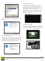
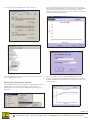
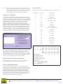
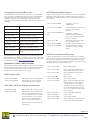
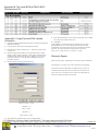
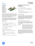
Telaire T6613/T6615 Series Development Kit User Manual Introduction Installing the T6613/6615 CO and Software The T6613/6615 development kit is a tool designed for evaluating the performance of the T6613/6615 CO2 sensor. In addition, this kit can be useful in developing software and/or firmware for use in communication with the T6613/6615 sensor. The T6613/6615 development kit contains: • • • This kit is intended for use by engineers and technicians who have a general understanding of electronics integration and/or communication; it is not intended as an end product. Although the included T6613/6615 CO2 sensor is a production PCB, it is not recommended to install it into a final product for resale. Key features include: • • • • • • • • One non-standard USB cable for communication with T6613/6615 Note: The T6613/6615 Development Kit provides a graphical interface to display and record CO2 measurements from the T6613/6615. The software also allows for calibration of the sensor with respect to known stable CO2 reference gas. The kit contains a USB drive preloaded with the necessary software. The sensor uses a special USB cable provided to connect to a PC; it is NOT intended for use as a standard USB cable. • • 2 Sensor Accuracy specification of ±75 ppm with ABC Logic Operates on standard 5.0 VDC UART communication compatible with most microcontrollers Tsunami-Lite software protocol for integration into existing software CO2 data logging and data export capability Single point calibration Complete software protocol documentation Binary files to load commands to the sensor with any terminal program No external cables - powered from a standard USB port USB Flash drive with all necessary software for operation and development Do not attempt to use this cable as a standard USB cable. One T6613/6615 CO2 sensor One 2 GB USB Flash drive with eCO2View software, drivers, user manual, software protocol and code samples. Hardware Installation The T6613/6615 CO2 OEM module is a sensor on a printed circuit board and should be treated as carefully as any other printed circuit board. Take appropriate precautions to prevent damage from electrostatic discharge, mechanical stresses, and thermal abuse during installation. Please refer to ANSI/ESD S20.20-1999 for more information on preventing ESD damage, and to IPC-610 Rev D for more information on proper electronic assembly practices. Software Requirements and Installation The software that comes with the T6613/6615 Development Kit has only been tested on Microsoft Windows XP Professional, Service Pack 2. While the software should work on all versions of Windows XP or later, this cannot be guaranteed. IMPORTANT: Install the software before plugging the device into the USB port. This will allow the software and USBserial drivers to be available before the device is connected for the first time. If the device is plugged in before the software is installed, it is recommended that you unplug the device and restart the PC. Once the PC has been successfully restarted, you can install the software and plug the device in again. The software comes on media that has an autorun.inf file in the root directory. This file instructs the operating system to automatically load all the files required. Insert the media into the PC and wait for the setup program to start. Note that if you are using a Flash drive, you might first be presented with the dialog box shown in Figure 1 on the next page. In this case, select “Install T6613/6615 Development Kit” and click OK to begin the installation process. Small profile of sensor allows for easy integration into any system. T63172-002 January 2009 Willow Technologies Ltd. + 44 (0) 1342 717102 Page 1 of 9 Unit 3 Borers Yard, Borers Arms Road, Copthorne, West Sussex, RH10 3LH, United Kingdom. + 44 (0) 1342 717014 [email protected] http://www.willow.co.uk W62014 Installing the Device Drivers A third party vendor supplies the device drivers for the USB communications software. The Setup Wizard should automatically load their driver installation software. However, if the software has to be loaded manually, then you can find that installation program in the default installation directory under the subdirectory VCP Driver. Run the program by double-clicking on the icon CDM 2.04.06.exe. During either manual or automatic loading, a DOS box will open and display the process. Note that during the automatic installation process, the document viewer might hide this DOS box if the check box “View Documentation” was checked. Figure 1: Removable Media Dialog The Setup Wizard (Figure 2 below) should appear after several seconds. If it does not, go to the root directory on the supplied media and run setup.exe. Figure 4: Device Driver DOS Installation Installing the Hardware Once the software has been loaded, you can plug the device into any available USB port and run the application software. First, plug the 4-pin receptacle into the 4-pin header on the T6613/6615 CO2 sensor (Figure 5 below). Next, plug the USB cable into the PC (Figure 6 below). Figure 2: Setup Wizard Window The Setup Wizard presents a number of dialogs. GE Sensing suggests that the user accept the default values. After the application software is loaded, the final dialog appears. Unless you want to load the device drivers manually, check the box “Load the VCP device drivers…” In the event the device drivers are already loaded, this checkbox should be unchecked. The software loads both the device driver manual installation program and documentation into the default directory, and they are available after installation. Figure 5: T6613/6615 CO2 Sensor with 4 Pin Header Figure 6: T6613/6615 CO 2 Sensor Connected to USB Cable Figure 3: Completing th e Software Installation Page 2 of 9 Willow Technologies Ltd. Unit 3 Borers Yard, Borers Arms Road, Copthorne, West Sussex, RH10 3LH, United Kingdom. + 44 (0) 1342 717102 + 44 (0) 1342 717014 [email protected] http://www.willow.co.uk W362013 The iterated communications port balloon shown in Figure 10 above may or may not be displayed. However, it is important to find out to which serial port the USB driver has iterated. If you are unsure which COM port is associated with the USB port, you can find that information in the Hardware tab in the Systems Properties dialog. 1. From the Start Menu, select the Control Panel, and from there select the System icon (Figure 12 below). Figure 7: T6613/6615 Hardware Setup On Windows XP systems, “New Hardware Found” balloons will appear on the screen (Figures 8, 9, 10 and 11 below). Figure 12: Start Menu – Control Panel 2. Select the System Properties icon (Figure 13 below). Figure 8: New Hardware Found – USB Serial Converter Figure 9: New Hardware Found -- USB Serial Port Figure 13: Control Panel – System Properties Icon 3. From the System Properties box (Figure 14 below), select the Hardware tab. Figure 10: New Hardware Found – Iterated Serial Port Figure 11: New Hardware Found — Ready to Use Figure 14: System Properties Window Page 3 of 9 Willow Technologies Ltd. Unit 3 Borers Yard, Borers Arms Road, Copthorne, West Sussex, RH10 3LH, United Kingdom. + 44 (0) 1342 717102 + 44 (0) 1342 717014 [email protected] http://www.willow.co.uk W362013 4. Click on the Device Manager button (Figure 15 below). If you are running this application for the first time, an error message appears that the communications port is not available. Continue running the application. In the eCO2View Settings menu (Figure 18 below), change the settings to the communications port to which the USB serial port driver iterated (Figure 19 below). Figure 15: Hardware Tab Figure 18: eCO2View Settings Menu Figure 16: Device Manager Window The USB software generally iterates to the next available open serial port: in Figure 16 above, port 7. Running the Development Software Figure 19: Serial Commu nications Port Window After you click OK, you must click the Start Graphing button to continue logging data. This may take several seconds, but eventually you should see data streaming to the graph area of the application (as shown in Figure 20 below). The Setup Wizard installs a shortcut on the user’s desktop and a group in the Start Menu. From the Start Menu (Figure 17 below), select eCO2View from the T6613/6615 Development Kit option to start the application. Figure 17: Start Menu – Development Software Figure 20: Running eCO2View Application Page 4 of 9 Willow Technologies Ltd. Unit 3 Borers Yard, Borers Arms Road, Copthorne, West Sussex, RH10 3LH, United Kingdom. + 44 (0) 1342 717102 + 44 (0) 1342 717014 [email protected] http://www.willow.co.uk W362013 Uninstalling the Software To uninstalling the application software, go to the Start Menu and select “T6613/6615 Development Kit, Version 1.0” (Figure 21 below) and then Uninstall. Clicking Uninstall deletes all of the files that were created in the installation directory (e.g., C:\Program Files\GE Sensing\T6613 (or T6615) Development Kit). If any files remain, simply delete any files left in the installation directory and the directories themselves. Uninstalling the Device Drivers The automated uninstall process does not uninstall the USB Serial Port device drivers. You must uninstall them manually in a straightforward procedure. From the Start Menu, select the Control Panel icon and then select the “Add or Remove Programs” icon (Figure 21 below). Developing an Application with the T6613/ 6615 CO 2 Sensor Simulating the Environment The T6613/6615 CO2 sensor has many different applications, so having a repeatable way to test the sensor under all conditions is vital to successful system integration. Although there are many different tests that one could conduct in order to verify or test the full functionality of any product, some critical issues are required in any application: • • • A clean 5.0 ± 5% VDC power supply capable of sourcing up to 200 mA peak, 35 mA average Reliable UART communications at 5.0V levels with the T6613/6615 Although the T6613/6615 is designed to withstand a large amount of RF exposure, it is still important to keep the sensor as far away as possible from antennas, transceivers and high voltage electronics that can radiate high levels of RF energy. This could degrade performance and give misguiding results. If any of the above points are not met, inaccurate readings or even damage to the sensor can occur. When simulating the environment, you should remember several factors when developing a test to fully encompass the reality of an application. Some of these factors include: • • Figure 21: Add or Remove Programs Icon You must remove two programs, both called “Windows Driver Package – FTDI CMD Driver Package”. Each is responsible for a different aspect of the USB Serial Port device driver. Click the Change/Remove button for both programs. • • • Temperature range of operation Exposure to external electrical stimulus (RF radiation, ground currents, etc...) Exposure to external chemical stimulus (combustion, corrosive chemicals, miscellaneous compounds found in gas under test, etc…) Any mechanical vibration or stresses applied to the sensor Start up and warm up time of system ABC Logic, Automatic Background Calibration System Figure 22: Removing Firs t Windows Driver Package Figure 23: Removing Second Windows Driver Package You have removed the device drivers. The T6613/6615 family of modules can be shipped with ABC Logic ON or OFF. ABC Logic is designed to work in environments where the measured CO2 level drops to outdoor levels at least three times in a 14day period. For example, in a typical office, school, theater, etc., people are the main source of CO2 in a building. When people go home at night, the indoor CO2 level will drop to the outdoor CO2 level, which is typically 380 to 400 ppm. The ABC Logic system records the lowest reading every 24-hour period for analysis. If a statistical difference is seen in the baseline readings, a calibration factor is applied to all subsequent sensor readings. The ABC Logic system typically takes three weeks of continuous run-time before making corrections. Please refer to http://www.gesensing.com/telaireproducts for more information about the ABC Logic system. ABC Logic should be turned OFF in applications that do not routinely see background levels such as in greenhouses where CO2 levels are kept elevated to promote plant growth. ABC Logic should also be turned OFF in any situation (i.e., calibration) where a gas of a concentration of less than 400 ppm is exposed to the sensor for a long period of time. In these situations, ABC Logic will create accuracy issues because it will try and make unnecessary adjustments. The 6613 module can be ordered with ABC Logic OFF. With ABC Logic OFF, GE Sensing suggests that you check the sensor’s calibration annually, and more often for harsh environments with high or low temperature, humidity, and/or dust. Page 5 of 9 Willow Technologies Ltd. Unit 3 Borers Yard, Borers Arms Road, Copthorne, West Sussex, RH10 3LH, United Kingdom. + 44 (0) 1342 717102 + 44 (0) 1342 717014 [email protected] http://www.willow.co.uk W362013 Note: During testing and development, it is recommended to turn the ABC Logic OFF. This can be easily done from the eCO2View program, under the “ABC_Logic” menu. Otherwise, after long term operation, the sensor will try to add correction values, which could prolong testing and corrupt logged data. Sensor Pin Out: The connector for the sensor is designated connector J1. The pin out is: Pin Number Pin Name Pin Description Single Point Calibration A TX UART Transmit A single point calibration will set what the sensor believes is a single concentration of CO2, and will shift each measurement correspondingly. The CO2 concentration in an open area outdoors, free of any obstruction, is typically around 380 to 400 ppm. This can serve as a reasonable single point calibration concentration. There are alternative calibration techniques. The first alternative is to soak the sensor in a known premixed concentration of gas and then execute the single point calibration sequence. If gas is being used, ensure the sensor readings are stable to ±10 ppm. The second alternative is to use the Telaire 7001 Reference sensor as a value for a single point calibration. To initial a single point calibration, open eCO2View. Under the Calibration menu, select Single Point Cal. A warning will appear specifying the proper condition for calibration. After verifying all the condition are met for calibration, select OK. A window similar to Figure 24 below appears: B RX UART Receive C V+ Input Voltage 5 VDC 1 V+ Input Voltage 5 VDC 2 GND Ground 3 GND Ground 4 AVOUT Analog Output 0-4 VDC ~ 0-2000 PPM CO2 5 N/C No Connect 6 N/C No Connect 7 N/C No Connect 8 N/C No Connect 9 N/C No Connect 10 TX UART Transmit 11 RX UART Receive 12 GND Ground Figure 24: eCO2View Single Point Calibration Menu Now enter the concentration of CO2 to which you wish to single point calibrate the sensor. Click Start Single Pt Cal. The process takes approximately two minutes to complete. When calibration is complete, click the Close button. The sensor will continue logging data. Feeding the correct sequence of bytes can also initiate the calibration. Please see the next page for single point calibration code command. Power and Input/Output Considerations When embedding the T6613/6615 CO2 sensor, you must take into account the power supply requirements and sensor pin outs. Power Supply Requirements The T6613/6615 requires a regulated 5.0 ±5% VDC supply. Large amounts of ripple voltage (100 mV+) on a supply can affect the sensor measurement. The average current draw for the sensor is 35 mA, with a peak current draw of 130 mA when the lamp is first activated. The quiescent current of the sensor is 8 mA. Be sure not to reverse the polarity on the power supply, as there is no protection in place to keep from destroying the electronics. While the input and output pins have ESD protection, you must still take care when installing a sensor, or when handling a sensor with any cables attached. Pin Description: TX - UART transmit pin RX - UART receive pin V+ - Positive voltage supply GND - Ground AVOUT - Analog voltage output of 0-4V based on CO 2 ppm N/C - No Connection Figure 25: T6613/6615 Pin Out Willow Technologies Ltd. Unit 3 Borers Yard, Borers Arms Road, Copthorne, West Sussex, RH10 3LH, United Kingdom. + 44 (0) 1342 717102 + 44 (0) 1342 717014 [email protected] http://www.willow.co.uk W362013 Communication with the T6613/6615 The T6613/6615 CO2 sensor has a whole syntax of commands for added versatility in applications. The document CO2_sensor_UART_Protocol Customer_rev3.pdf, included with this media, provides a full description of the command protocol for the T6613/6615. In this file is a description of the frame size and packet formatting, and full details on the different serial commands for the T6613/6615. Commonly Used Commands For convenience, here are some commonly used commands when talking to the T6613/6615. Loopback: This command is used strictly for testing. The data_bytes (up to 16 bytes) following the 0x00 command are echoed back in the response packet. Send: FF FE 04 00 11 22 33 Expected Reply: FF FA 03 11 22 33 Status: Read a status byte from the sensor. The status byte indicates whether the sensor is functioning, and is measuring PPM concentrations. The response is a single byte, <status>, of bit flags. (Note: bit 0 is the LSB.) Bit 0: Error Verify Single Pt PPM equals 600 (= 0x0258): This is the second step in a single point calibration. This command will verify a Set Single Pt PPM command, and is a recommended step every time the sensor is to be calibrated. Send: Expected Reply: FF FE 02 02 11 FF FA 02 02 58 Single Point Calibration Command: This command tells the sensor to start a single point calibration. Before sending this command, the sensor should be soaking in uniform calibration gas, and a Set Single PT PPM and Verify Single PT PPM command should have successfully been done. The <ACK> response indicates that the calibration request has been received. To verify that the calibration has started, wait at least one dsp cycle length and then send command “Status” to see if the calibration bit is set. When the calibration is finished, the calibration bit in the status byte is cleared. A Read PPM command should be executed after the single point calibration process is complete to verify successful calibration. Send: Expected Reply: FF FE 01 9B FF FA 00 (ACK) Bit 1: Warm up Mode Set Altitude equal 500 Feet (500 = 0x01F4): Set/Write the elevation in feet above sea level, a required operating parameter for the sensor. Elevation is normally expressed in increments of 500 feet from 0 to 5000 feet. Response is an <ACK>, a response data-packet with the length byte set to zero and no data bytes. This command should be followed by a Verify Altitude Command to ensure the expected value was written. Bit 2: Calibration Bit 3: Idle Mode Bits 4 - 6: (internal) Bit 7: Self-Test Mode If a given status bit is “1”, the sensor is in that mode. If a status bit is “0”, the sensor is not in that mode. Send: FF FE 04 03 0F 01 F4 Send: FF FE 01 B6 Expected Reply: FF FA 00 (ACK) FF FA 01 00 (Normal Mode) FF FA 01 02 (Warm-up) FF FA 01 04 (Calibration) Verify Altitude equals 500 Feet: This command tells the sensor to output the current setting for the altitude that is stored in Flash memory. Expected Reply: Read PPM: Read the gas ppm as measured by the sensor. Response is a 2-byte binary value giving the ppm. Send: FF FE 02 02 03 Possible Reply: FF FA 02 02 8A (for PPM = 650 = 0x028A) Send: FF FE 02 02 0F Expected Reply: FF FA 02 01 F4 Set Single Pt PPM equal 600 (= 0x0258): This is the first step to doing a single point calibration. This command tells the sensor what the current measurement of CO2 should be reading. Send: Expected Reply: FF FE 04 03 11 02 58 FF FA 00 (ACK) Page 7 of 9 Willow Technologies Ltd. Unit 3 Borers Yard, Borers Arms Road, Copthorne, West Sussex, RH10 3LH, United Kingdom. + 44 (0) 1342 717102 + 44 (0) 1342 717014 [email protected] http://www.willow.co.uk W362013 Using HyperTerminal and Binary Files UART Read and Update Elevation You can upload individual commands to the sensor in many different ways. Any RS-232 communication monitor tool can send hexadecimal commands to the sensor, and also monitor the replies. The software includes a set of binary files, containing the commands for single instructions. The table below lists the name of the file, and its associated command: In this set of interchanges, you first read the sensor’s elevation parameter and find it is set at 1000 ft. Then you change the elevation setting to 2500 ft. Then you read back the new elevation setting and verify that it is set to 2500 ft. File Name Command Description Loopback.bin Send loopback command Read_PPM.bin Return current ppm measurement Set_Alt_500.bin Set sensor altitude to 500 feet Set_SngPt_600.bin Set single point ppm to 600 ppm SngPt_Cal_Cmd.bin Initiate a single point calibration Status.bin Return the status register Verify_Alt_500.bin Verify current altitude at 500 feet Verify_SngPt_600.bin Verify single point equals 600 command HyperTerminal, included in this development kit, allows easy uploading of commands. Please see Appendix C for file upload instructions. An RS-232 debug tool or monitor is required to verify communication with the sensor, and also for general-purpose development work. GE Sensing recommends LookRS232 (http://www.lookrs232.com/). Appendix A: Basic Code Examples The following examples illustrate request and response packets with the UART Tsunami-Lite Communication Protocol. Requests and responses are expressed in hexadecimal bytes. The <command> portion of a request and the <response_data> are in bold type. UART Read Gas PPM Req> FF FE 02 02 03 In the request “02 03” is CMD_READ Resp> FF FA 02 02 50 The response “05 50” gives the gas PPM as 592 PPM (592 = 0x0250). Req 1> FF FE 02 02 0F In request 1, “02 0F” is CMD_READ, Resp1>.FF FA 02 03 E8 In the first response, “03 E8” is the elevation, 1000 ft (1000 = 0x03E8). Req 2> FF FE 04 03 0F 09 C4 In request 2, “03 0F” is CMD_UPDATE, ELEVATION, and “09 C4” is the elevation, 2500 ft (2500 = 0x09C4). Resp2> FF FA 00 The second response is an <ACK>, since the length is 0x00. Req 3> FF FE 02 0F 02 The third request and response are formatted like the first, reading back the new elevation setting, 2500 ft. Resp3> FF FA 02 09 C4 UART Error Simulation with Recovery In this set of interchanges, you first verify that the sensor is operating normally. Then you send a command that forces the sensor into an error state. The sensor automatically recovers by resetting itself, and going into Warm-up Mode. You then send the command to skip warm-up, thus putting the sensor back into the normal state. Req 1> FF FE 01 B6 Req 1: CMD_STATUS. Resp1> FF FA 01 00 Resp1: status byte is 0x00. Sensor is in normal mode, measuring gas PPM. Req 2> FF FE 01 95 Req 2: CMD_HALT. Puts sensor in error mode. Resp2> FF FA 00 Resp2: <ACK> Req 3> FF FE 01 B6 Req 3: CMD_STATUS. Resp3> FF FA 01 02 Resp3: status byte is 0x02. Bit 1 high indicates sensor is in warm-up mode. (If CMD_STATUS is sent quickly enough, the sensor may respond with 0x01, indicating the brief error state prior to reset, or may not respond at all due to resetting) Req 4> FF FE 01 91 Req 4: CMD_SKIP_WARMUP Resp4> FF FA 00 Resp4: <ACK> Req 5> FF FE 01 B6 Req 5: CMD_STATUS Resp5> FF FA 01 00 Resp5: status byte is 0x00. Sensor is in normal mode, measuring gas PPM. UART CMD_STATUS to Verify Normal Operation Req> FF FE 01 B6 In the request, “B6” is CMD_STATUS Resp> FF FA 01 00 In the response, “00” is the status byte. The zero value indicates that the sensor is in normal mode where it is measuring gas PPM. It is not in warm-up mode, it is not in calibration mode, and it is not in an error condition. Further examples of CMD_STATUS appear below. Page 8 of 9 Willow Technologies Ltd. Unit 3 Borers Yard, Borers Arms Road, Copthorne, West Sussex, RH10 3LH, United Kingdom. + 44 (0) 1342 717102 + 44 (0) 1342 717014 [email protected] http://www.willow.co.uk W362013 Appendix B: Top Level BOM of T6613/6615 Development Kit Appendix C: HyperTerminal File Upload Procedure 1. Open the file HyperTerminal.ht in the T6613/6615 Development Kit installation directory 2. Click on the File menu, then click New Connection. 3. Enter the name of the connection (e.g., “T6613/6615 CO2 Sensor Connection”) 4. Select the appropriate COM port. In applications where a USB interface with a Virtual COM port is used, please check the Ports (COM and LPT) menu under the Device Manager for the correct COM port number. To access the Device Manager, follow the procedure on page 3. 5. Set the COM port settings per the following: 7. Select the desired binary file to transfer. The binary files included are located in the folder named “bin”. 8. Click Open. Clicking Open will send the desired command to the unit. The HyperTerminal won’t receive anything from the sensor, but the command has been sent and the sensor has preformed the desired operation. For a full description of the protocol, please see CO2_sensor_UART_Protocol - Customer_rev3.pdf. Warranty Repairs Please contact Willow Technologies for warranty repair information. This product is covered by one or more of the following patents: 5,650,624/5,721,430/5,444,249/5,747,808/5,834,777/5,163,332/ 5,340,986/5,502,308/6,344,798/6,023,069/5,370,114/5,601,079/ 5,691,704/5,767,776/5,966,077/6,107,925/5,798,700/5,945,924/ 5,592,147/6,255,653/6,250,133/6,285,290 Bits per second = 19200 Data bits = 8 Parity = None Stop bits = 1 Flow control = None 6. Next, under the Transfers menu, click on Send Text File… Page 9 of 9 Willow Technologies Ltd. Unit 3 Borers Yard, Borers Arms Road, Copthorne, West Sussex, RH10 3LH, United Kingdom. + 44 (0) 1342 717102 + 44 (0) 1342 717014 [email protected] http://www.willow.co.uk W362013