1
PC1616/PC1832/PC1864 v4.5 NA
,Q VWD O O D WL R Q *X L G H
:$51,1*7KLVPDQXDOFRQWDLQVLQIRUPDWLRQRQOLPLWDWLRQVUHJDUGLQJSURGXFWXVHDQGIXQFWLRQDQGLQIRUPDWLRQRQ
WKHOLPLWDWLRQVDVWROLDELOLW\WKHPDQXIDFWXUHU7KHHQWLUHPDQXDOVKRXOGEHUHDGFDUHIXOO\
Table of Contents
Guidelines for Locating Smoke Detectors and CO Detectors . . . . . . . . . . . . . . . . . . . . . . . . . . . . . . . . . . ii
Chapter 1 Installation & Wiring . . . . . . . . . . . . . . . . . . . . . . . . . . . . . . . . . . . . . . . . . . . . . . . . . . . . . . . . . . 1
Installation . . . . . . . . . . . . . . . . . . . . . . . . . . . . . . . . . . . . . . . . . . . . . . . . . . . . . . . . . . . . . . . . . . . . . . 1
1.1 Keybus Wiring . . . . . . . . . . . . . . . . . . . . . . . . . . . . . . . . . . . . . . . . . . . . . . . . . . . . . . . . . . . . . . . . 3
1.2 Zone Wiring . . . . . . . . . . . . . . . . . . . . . . . . . . . . . . . . . . . . . . . . . . . . . . . . . . . . . . . . . . . . . . . . . . 3
1.3 Zone Expanders . . . . . . . . . . . . . . . . . . . . . . . . . . . . . . . . . . . . . . . . . . . . . . . . . . . . . . . . . . . . . . . 3
1.4 Bell Wiring . . . . . . . . . . . . . . . . . . . . . . . . . . . . . . . . . . . . . . . . . . . . . . . . . . . . . . . . . . . . . . . . . . . 3
1.5 AUX Power Wiring . . . . . . . . . . . . . . . . . . . . . . . . . . . . . . . . . . . . . . . . . . . . . . . . . . . . . . . . . . . . . 4
1.6 PGM Wiring . . . . . . . . . . . . . . . . . . . . . . . . . . . . . . . . . . . . . . . . . . . . . . . . . . . . . . . . . . . . . . . . . . 4
1.7 Carbon Monoxide Detector Wiring . . . . . . . . . . . . . . . . . . . . . . . . . . . . . . . . . . . . . . . . . . . . . . . . . 4
1.8 Telephone Line Wiring . . . . . . . . . . . . . . . . . . . . . . . . . . . . . . . . . . . . . . . . . . . . . . . . . . . . . . . . . . 5
1.9 Ground . . . . . . . . . . . . . . . . . . . . . . . . . . . . . . . . . . . . . . . . . . . . . . . . . . . . . . . . . . . . . . . . . . . . . . 5
1.10 Battery . . . . . . . . . . . . . . . . . . . . . . . . . . . . . . . . . . . . . . . . . . . . . . . . . . . . . . . . . . . . . . . . . . . . . 5
1.11 AC Wiring . . . . . . . . . . . . . . . . . . . . . . . . . . . . . . . . . . . . . . . . . . . . . . . . . . . . . . . . . . . . . . . . . . . 5
Chapter 2 User Commands . . . . . . . . . . . . . . . . . . . . . . . . . . . . . . . . . . . . . . . . . . . . . . . . . . . . . . . . . . . . 6
2.1 Away Arming . . . . . . . . . . . . . . . . . . . . . . . . . . . . . . . . . . . . . . . . . . . . . . . . . . . . . . . . . . . . . . . . . 6
2.2 Stay Arming . . . . . . . . . . . . . . . . . . . . . . . . . . . . . . . . . . . . . . . . . . . . . . . . . . . . . . . . . . . . . . . . . . 6
2.3 Disarming . . . . . . . . . . . . . . . . . . . . . . . . . . . . . . . . . . . . . . . . . . . . . . . . . . . . . . . . . . . . . . . . . . . . 6
2.4 [] Commands . . . . . . . . . . . . . . . . . . . . . . . . . . . . . . . . . . . . . . . . . . . . . . . . . . . . . . . . . . . . . . . . 6
2.5 Function Keys . . . . . . . . . . . . . . . . . . . . . . . . . . . . . . . . . . . . . . . . . . . . . . . . . . . . . . . . . . . . . . . . 8
Chapter 3 Programming . . . . . . . . . . . . . . . . . . . . . . . . . . . . . . . . . . . . . . . . . . . . . . . . . . . . . . . . . . . . . . . 9
3.1 Template Programming . . . . . . . . . . . . . . . . . . . . . . . . . . . . . . . . . . . . . . . . . . . . . . . . . . . . . . . . . 9
3.2 DLS Programming . . . . . . . . . . . . . . . . . . . . . . . . . . . . . . . . . . . . . . . . . . . . . . . . . . . . . . . . . . . . 9
3.3 Advanced Keypad Programming . . . . . . . . . . . . . . . . . . . . . . . . . . . . . . . . . . . . . . . . . . . . . . . . . 9
Chapter 4 Programming Descriptions . . . . . . . . . . . . . . . . . . . . . . . . . . . . . . . . . . . . . . . . . . . . . . . . . . . 11
Chapter 5 Programming Worksheets . . . . . . . . . . . . . . . . . . . . . . . . . . . . . . . . . . . . . . . . . . . . . . . . . . . . 27
5.1 Index to Programming Worksheets . . . . . . . . . . . . . . . . . . . . . . . . . . . . . . . . . . . . . . . . . . . . . . . 27
Appendix A: Reporting Codes . . . . . . . . . . . . . . . . . . . . . . . . . . . . . . . . . . . . . . . . . . . . . . . . . . . . . . . . . 53
Appendix B: UL Listed Commercial and Residential Installations . . . . . . . . . . . . . . . . . . . . . . . . . . . . . . 55
Appendix C: SIA False Alarm Reduction . . . . . . . . . . . . . . . . . . . . . . . . . . . . . . . . . . . . . . . . . . . . . . . . . 56
Appendix D: Troubleshooting Guide . . . . . . . . . . . . . . . . . . . . . . . . . . . . . . . . . . . . . . . . . . . . . . . . . . . . 57
Appendix E: Template Programming . . . . . . . . . . . . . . . . . . . . . . . . . . . . . . . . . . . . . . . . . . . . . . . . . . . . 61
Appendix F: Communicator Format Options . . . . . . . . . . . . . . . . . . . . . . . . . . . . . . . . . . . . . . . . . . . . . . 63
SAFETY INSTRUCTIONS FOR SERVICE PERSONNEL . . . . . . . . . . . . . . . . . . . . . . . . . . . . . . . . . . . . . . . 66
FCC COMPLIANCE STATEMENT . . . . . . . . . . . . . . . . . . . . . . . . . . . . . . . . . . . . . . . . . . . . . . . . . . . . . . . . . 69
i
PowerSeries - PC1616/PC1832/PC1864
Guidelines for Locating Smoke Detectors and CO Detectors
The following information is for general guidance only and it is recommended that local fire codes and regulations be consulted when locating
and installing smoke and carbon monoxide alarms.
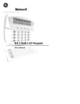
Smoke Detectors
Research indicates that all hostile fires in homes generate smoke to a greater or lesser extent. Detectable quantities of smoke precede detectable
levels of heat in most cases. Smoke alarms should be installed outside of each sleeping area and on each level of the home.
DSC recommends that additional smoke alarms beyond those required for minimum protection be installed. Additional areas that should be
protected include: the basement; bedrooms, especially where smokers sleep; dining rooms; furnace and utility rooms; and any hallways not
protected by the required units.
On smooth ceilings, detectors may be spaced 9.1m (30 feet) apart as a guide. Other spacing may be required depending on ceiling height, air
movement, the presence of joists, uninsulated ceilings, etc. Consult National Fire Alarm Code NFPA 72, CAN/ULC-S553-02 or other appropriate national standards for installation recommendations.
• Do not locate smoke detectors at the top of peaked or gabled ceilings; dead air space in these locations may prevent smoke detection.
• Avoid areas with turbulent air flow, such as near doors, fans or windows. Rapid air movement around the detector may prevent smoke from
entering the unit.
• Do not locate detectors in areas of high humidity.
• Do not locate detectors in areas where the temperature rises above 38oC (100oF) or falls below 5oC (41oF).
• Smoke detectors should always be installed in USA in accordance with Chapter 11 of NFPA 72, the National Fire Alarm Code: 11.5.1.1. :
Where required by applicable laws, codes, or standards for a specific type of occupancy, approved single- and multiple-station smoke alarms
shall be installed as follows:
(1) In all sleeping rooms and guest rooms.
(2) Outside of each separate dwelling unit sleeping area, within 6.4 m (21 ft) of any door to a sleeping room, the distance measured along a path of travel.
(3) On every level of a dwelling unit, including basements.
(4) On every level of a residential board and care occupancy (small facility), including basements and excluding crawl spaces and unfinished attics.
(5) In the living area(s) of a guest suite.
(6) In the living area(s) of a residential board and care occupancy (small facility).
Figure 3
Figure 1
Figure 2
Figure 3a
Figure 4
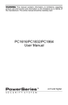
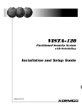
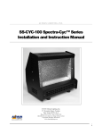
CO Detectors
Carbon monoxide gas moves freely in the air. The human body is most vulnerable to the effects of CO gas
during sleeping hours. For maximum protection, a CO alarm should be located outside primary sleeping
areas or on each level of your home. Figure 5 indicates the suggested locations in the home. The electronic sensor detects carbon monoxide, measures the concentration and sounds a loud alarm before a
potentially harmful level is reached.
Do NOT place the CO alarm in the following areas:
• Where the temperature may drop below -10ºC or exceed 40 ºC.
• Near paint thinner fumes.
• Within 5 feet (1.5 meters) of open flame appliances such as furnaces, stoves and fireplaces.
• In exhaust streams from gas engines, vents, flues or chimneys.
• In close proximity to an automobile exhaust pipe; this will damage the detector.
ii
BEDROOM
BEDROOM
BEDROOM
GROUND
FLOOR
KITCHEN
GARAGE
BASEMENT
CARBON MONOXIDE DETECTOR
Figure 5
&KDSWHU,QVWDOODWLRQ:LULQJ
&KDSWHU,QVWDOODWLRQ:LULQJ
This Installation Guide provides the basic installation, wiring and programming information required to program the PowerSeries PC1616,
PC1832, and PC1864 control panels.
All necessary information required to meet UL Listing requirements is included in this document.
7HFKQLFDO6XPPDU\
FEATURES
PC1616
PC1832
PC1864
2QERDUG=RQHV
+DUGZLUHG=RQHV
[3&
[3&
[3&
:LUHOHVV=RQHV
.H\SDG=RQH6XSSRUW
2QERDUG3*0
2XWSXWV
3*0P$
3*0P$
3*0P$
3*0P$
3*0P$
3*0P$
3*0([SDQVLRQ
[P$3&
[P$3&
[P$3&
[P$3&
[P$3&
[P$3&
.H\SDGV
3DUWLWLRQV
63(&,),&$7,216
8VHU&RGHV
0DVWHU&RGH
0DVWHU&RGH
0DVWHU&RGH
7HPS5DQJH r&r&r)r)
+XPLGLW\0D[ 5+
3RZHU6XSSO\ 9$&9$#+]
&XUUHQW'UDZ3DQHO P$QRP
$X[2XWSXW 9'&P$
%HOO2XWSXW 9'&P$
(YHQW%XIIHU
(YHQWV
(YHQWV
(YHQWV
7UDQVIRUPHU5HTXLUHG
9$&9$
9$&9$
9$&9$
%DWWHU\5HTXLUHG
$K$K$+U
$K$K$+U
$K$K$+U
%HOO2XWSXW
9P$FRQW
9P$FRQW
9P$FRQW
OUT Of THE BOX
4W\ 4W\ 4W\ 4W\ 4W\ 4W\ 4W\ 4W\ 4W\ 4W\ 4W\ &DELQHW
3&0RGXOH
,QVWDOODWLRQ*XLGH
8VHU0DQXDO
&DELQHW/DEHO
&DELQHW'RRU3OXJ
6WDQGRIIV
.5HVLVWRUV
.5HVLVWRU
.5HVLVWRU
*URXQGLQJ.LW
&203$7,%/('(9,&(6
.H\SDGV %DFNZDUGFRPSDWLEOHZLWKDOO3RZHU6HULHVNH\SDGV
0RGXOHV
3.;;.H\SDGP$PD[
5).;;.H\SDG P$PD[
/&')L[HG0HVVDJH/&'.H\SDG P$PD[
/('=]RQH/('.H\SDG P$PD[
TL-250/TL300 Communicator ............................................275/350mA
GS2060/GS2065 (GPRS/GSM only)...........................................65mA
GS2060-SM (GPRS only) ...........................................................90mA
TL260GS/TL265GS (Ethernet/GPRS) ......................................100mA
TL260-SM (Ethernet only) .........................................................100mA
TL260GS-SM (Ethernet/GPRS only).........................................120mA
PC5100 2-wire Interface............... 40mA plus devices to 170mA max.
RF5132-433 Wireless Receiver ...............................................125mA
RF5108-433 Wireless Receiver ...............................................125mA
PC5108 Zone Expander .............................................................30mA
PC5200 Power Supply ................................................................20mA
PC5204 Power Supply with 4 Programmable Outputs................30mA
PC5208 Low Current Programmable Output Module .................50mA
Escort5580 Telephone Interface Module ................................... 130m
&DELQHWV
3&& [[PP[[LQ
3&&UHVLGHQWLDOEXUJRQO\ [[PP[[LQ
3&&$58/FRPPHUFLDOEXUJ [[PP[[LQ
&0&8/FRPPHUFLDOEXUJ [[PP[[LQ
6XWWOH6$( [[PP[[LQ
6XWWOH6$( [[PP[[LQ
6XWWOH6$( [[PP[[LQ
6XWWOH6$( [[PP[[LQ
*The T-Link TL-150 is not UL/ULC listed
&ODVVLILHGLQ$FFRUGDQFHZLWK$16,6,$&36,$)$5
,167$//$7,21
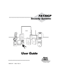
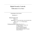
Begin the installation by mounting additional modules in the cabinet using the stand-offs provided, then mount the cabinet in a dry, protected
area with access to unswitched AC power. Install hardware in the sequence indicated in the following pages. Do NOT apply power until installation is complete.
All wiring entry points are designated by arrows. All circuits are classified UL power limited except for the battery leads. Minimum 1/4”
(6.4mm) separation must be maintained at all points between power limited and non-power limited wiring and connections.
PowerSeries - PC1616/PC1832/PC1864
3&:LULQJ'LDJUDP
North America Only
POWER LIMITED
Stand Off
PC Board
Cable Tie (not supplied) recommended
Cabinet
2. Position circuit board
mounting holes over
standoffs. Press firmly
on board to snap-in-place.
DSC
UA503
Primar y:120VAC/60Hz.
Secondary: 16.5VAC 40VA
DSCPTD 1640U
Class II Transformer
220
1. Inser t Stand off into cabinet
mounting hole in the
desired location. Snap-inplace.
PC1616/1832/1864
WARNING:
NOTE: Do not connect
transformer to receptacle
controlled by a switch
High Voltage. Disconnect AC Power
and telephone lines before servicing
PC1864
PC1832
Only
PC1864
Only
CON1
BAT+BAT-
TB-2
AC AC
AUX+
BELL+
PGM1
PGM3
AUXBELL- RED BLK YEL GRN
PGM2
PGM4 Z1 COM Z2
Z3 COM Z4
Z5 COM Z6
Z7 COM Z8 EGND
RING
TIP
R-1
T-1
230 VAC/50 Hz International
See ground wiring
diagram in the Installation
section of this manual
CON1
BAT+BATAC AC
12V / 7 AHr
To EGND
Terminal
12V / 7 AHr
BLACK
16.5VAC/40VA
RED
DSC Model BD7-12
or equivalent
NON-POWER LIMITED
Battery
StandbyTime:
24Hrs min.
FUSE
WARNING: Incorrect connections may result in PTC failure or improper operation.
Inspect wiring and ensure connections are correct before applying power.
Incorrect connection of batteries may result in battery rupture or Fire Hazard.
Do NOT allow metal objects to connect the Positive and Negative Terminals.
Ensure that batteries are connected with correct polarity [Red to (+), Black to (-)].
Failure to comply with this may result in battery rupture and/or Fire Hazard.
All circuits are classified for UL Installations as Power Limited/Class II Power Limited
except for battery leads which are not power limited.
IMPORTANT:
Do NOT route any wiring over circuit boards. Maintain at least 1"(25.4mm) separation.
A minimum of 1/4" (6.4mm) separation must be maintained at all points between
power limited wiring and all other non-power limited wiring.
UA503
220
a)This equipment, Alarm Controller PC1616/1832/1864 shall
be installed and used within an environment that provides the
pollution degree max 2 and overvoltages category II
NON-HAZARDOUS LOCATIONS, indoor only. The equipment is
FIXED and PERMANENTLY connected and is designed to be
installed by ser vice persons only; [ser vice person is defined as a
person having the appropriate technical training and experience
necessar y to be aware of hazards to which that person may be
exposed in performing a task and of measures to minimize the risks
to that person or other persons.]
b)The connection to the mains supply must be made as per the local
authorities rules and regulations.
An appropriate disconnect device must be provided as par t of the
building installation. Where it is not possible to rely on identification of
the neutral in the AC Mains supply the disconnecting device must
disconnect both poles simultaneously (line and neutral). The device
shall disconnect the supply during servicing.
PC1616/1832/1864
PC-LINK
AUX+ and Keybus (Red) are Internally Connected
Total current draw from Keypads, PGM Outputs and
Aux circuits must not exceed 700mA
c)The equipment enclosure must be secured to the building structure
before operation.
PC1864
Only
PC1864
PC1832
Only
CON1
BAT+BAT-
TB-2
AC AC
+ AUX -
+ BELL -
RED BLK YEL GRN 1 PGM 2 3 PGM 4 Z1 COM Z2 Z3 COM Z4 Z5 COM Z6 Z7 COM Z8 EGND RING TIP R-1 T-1
Keybus
DG009606
10
Internally Connected
e)Internal wiring must be routed in a manner that prevents:
- Excessive strain on wire and on terminal connections;
- Loosening of terminal; connections;
- Damage of conductor insulation
f) Disposal of the used batteries shall be made according to the waste
recovery and recycling regulations applicable to the intended market.
DSC
REV XX
WARNING:
High Voltage. Disconnect AC Power
and telephone lines before servicing
PGMs
Zones
Telephone
&KDSWHU,QVWDOODWLRQ:LULQJ
.H\EXV:LULQJ
The 4-wire KEYBUS (red, black, yellow and green) is the communication connection between the control panel and all modules. The 4 KEYBUS terminals of all modules must be connected to the 4 KEYBUS terminals of the main control panel.
The following rules must be followed when wiring the Keybus:
• Minimum 22 AWG wire, max. 18 AWG (2-wire twisted preferred)
• Do not use shielded wire
• Modules can be home run, connected in series or T-tapped, provided that
the maximum wire distance from the control panel to any module does not
exceed 1,000 feet (305m)
• No more than 3,000 feet (915m) of wire can be used in total
150’ (46m)
150’ (46m)
500’ (152m)
CONTROL
PANEL 500’ (152m)
=RQH:LULQJ
Zones can be wired for Normally Open or Normally Closed contacts, with
Single-End-of-Line (SEOL) or Double End-of-Line (DEOL) resistors.
Observe the following guidelines:
• For UL Listed Installations use SEOL or DEOL only.
• Minimum 22 AWG wire, maximum 18 AWG
• Do not use shielded wire
• Wire run resistance shall not exceed 100Refer to the chart below:
Normally Closed Loops - Do NOT use for UL Installations
Single End-of-Line Resistor Wiring
%XUJODU\=RQH:LULQJ&KDUW
:LUH
*DXJH
0D[LPXP:LUH/HQJWKWR
(QGRI/LQH5HVLVWRUIWPHWHUV
)LJXUHVDUHEDVHGRQPD[LPXPZLULQJUHVLVWDQFHRI
•
•
•
•
[001]-[004] Selects Zone Definition
[013] Opt [1] Selects Normally Closed or EOL resistors
[013] Opt [2] Selects SEOL or DEOL resistors
[101]-[108] Opt [14], [15], [16] Selects Normally Closed SEOL or DEOL
for on-board zones (PC1832/1864, Zone 1-8; PC1616, Zones 1-6)
=RQH6WDWXV/RRS5HVLVWDQFH/RRS6WDWXV
• Fault - 0 (shorted wire/loop)
• Secure - 5600 (contact closed)
Double End-of-Line Resistor Wiring
• Tamper - infinite (broken wire, open)
• Violated - 11,200 (contact open)
=RQH([SDQGHUV
Zone expanders add zones in groups
of eight to the Alarm system. Module
jumpers J1, J2, J3 are required to
assign zones to these modules.
Jumper settings for PC5108 v2 are
shown here.
• PC5108 v1.0 supports first 32
zones only.
• PC5700 enrolls as two modules
• Do NOT use PC5108 v1 and
PC5108 v2 on the same panel.
Module
Jumpers
J1
J2
ON
OFF
ON
OFF
ON
OFF
ON
OFF
ON
ON
OFF
OFF
ON
ON
OFF
OFF
Zones
Assigned
J3
ON
ON
ON
ON
OFF
OFF
OFF
OFF
Zones Disabled
Zones 09-16
Zones 17-24
Zones 25-32
Zones 33-40
Zones 41-48
Zones 49-56
Zones 57-64
Refer to the associated installation sheet for Jumper locations
for the PC5108 v1 and PC5700.
%HOO:LULQJ
These terminals supply 700mA of current at 12VDC for commercial installations and 11.1-12.6VDC for
residential installations (e.g. DSC SD-15 WULF). To comply with NFPA 72 Temporal Three Pattern
requirements: Program [013] Opt [8] ON. Note that Steady, Pulsed alarms are also supported.
The Bell output is supervised and power limited by 2A PTC. If unused, connect a 1000 resistor across
Bell+ and Bell- to prevent the panel from displaying a trouble. See [][2].
PowerSeries - PC1616/PC1832/PC1864
$8;3RZHU:LULQJ
The control panel can provide a maximum of 700mA of current for modules, powered detectors, relays, LEDs, etc. If the total current required
exceeds 700mA an additional power supply is required (e.g., PC5200, PC5204). See list below.
Min/max operating voltages for devices, sensors and modules is 9.5VDC - 14VDC.
3*0:LULQJ
PGMs switch to ground when activated from the control panel. Connect the
positive side of the device to be activated to the AUX+ Terminal. Connect the
negative terminal to the PGM.
Current output is as follows:
•
PGM 1, 3, 4
50mA
•
PGM 2
300mA
For current levels greater than 300mA, a relay is required.
PGM2 can also be used for 2-wire smoke detectors.
NOTE: Use SEOL resistors on fire zones only.
PGM 1, LED output with current limiting resistor and
Optional Relay driver output
:LUH6PRNH'HWHFWRUV,QLWLDWLQJ&LUFXLW
• Style B (Class B), Supervised, Power Limited
• UL Compatibility Identifier . . . . . . . . . . . . . . . . . . . . . . . . . . . . . . . PC18-1
• DC Output Voltage . . . . . . . . . . . . . . . . . . . . . . . . . . . . . . . .9.8-13.8 VDC
• Detector Load . . . . . . . . . . . . . . . . . . . . . . . . . . . . . . . . . . . . .2mA (MAX)
• Single End-of-Line (SEOL) Resistor. . . . . . . . . . . . . . . . . . . . . . . . .2200
• Loop Resistance. . . . . . . . . . . . . . . . . . . . . . . . . . . . . . . . . . . . 24(MAX)
• Standby Impedance . . . . . . . . . . . . . . . . . . . . . . . . . . . . . . . 1020
• Alarm Impedance. . . . . . . . . . . . . . . . . . . . . . . . . . . . . . . . . . 570(MAX)
• Alarm Current . . . . . . . . . . . . . . . . . . . . . . . . . . . . . . . . . . . .89mA (MAX)
8/&RPSDWLELOLW\,')RU)6$%6HULHVLV)6
NOTE: For ULC Listed installations use FSA-210A and FSA-410A series.
:LUH6PRNH'HWHFWRUV
RM-1/RM-2 POWER LOOP
SUPERVISORY RELAY
12VDC
2200 Ohm
END-OF-LINE
RESISTOR
EOLR-3
ALARM
INITIATING
LOOP
RESISTANCE
100 Ohm
EOLR-2
END-OF-LINE
RESISTOR
5600 Ohm, 0.5W
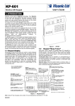
&DUERQ0RQR[LGH'HWHFWRU:LULQJ
The following CO Detector models can be used with
PC1616/PC1832/PC1864 v4.5 (and higher) control panels:
• Potter Model CO-12/24, UL File E321434
• Quantum Model 12-24SIR, UL File E186246
• NAPCO Model FW-CO12 or FW-CO1224, UL File E306780
• System Sensor Model CO1224, UL File E307195
NOTE: Wireless CO Detectors are also available, please refer to
the RF5132 Installation Manual for details.
CO DETECTOR
POWER
- +
ALARM
NC
C
TROUBLE
NO NC
C
NO
-
(SEOL TYPE 41)
RM-1/RM-2
POWER LOOP
SUPERVISORY
RELAY
(12VDC, 35mA)
SEOL
RESISTOR
(5600 ohm)
+
ZONE
INPUT
ANY ANY
COM Z
DG009477
+-
AUX
PC1616/1832/1864
ALARM
INITIATING
LOOP
RESISTANCE
100 ohm
NOTE: For multiple unit connections, the leads between CO detectors need to be broken. The power supervision relay has to be powered from the last detector in the loop.
When installing wireless CO detectors, use only DSC model
WS4913. A DSC wireless receiver model RF5132-433 v5.1
(and higher) or DSC keypad receiver models RFK55XX-433
(xx= 00/01/08/16) v1.2 (and higher) are required when installing wireless CO detectors.
&KDSWHU,QVWDOODWLRQ:LULQJ
7HOHSKRQH/LQH:LULQJ
Wire the telephone connection terminals (TIP, Ring, T-1, R-1) to an RJ-31x
Connector as indicated. For connection of multiple devices to the telephone
line, wire in the sequence indicated. Use 26 AWG wire minimum for wiring.
Telephone format is programmed in option [350].
Telephone Call Directions are programmed in options [351]-[376].
T-1
R-1
TIP
RING
BRN
GRA
GRN
RED
RJ-31X
*URXQG
Ground Installation
Tighten nut to break paint and make
good connection to the cabinet
%DWWHU\
Standby Battery Guide
Battery Charging Current: 400 mA
Battery
Standby
Size
4Hr
24Hr
$KU
$KU
$KU
P$
P$
P$
P$
P$
A sealed, rechargeable, lead acid battery or gel type battery is required to
meet UL requirements for power standby times.
NOTE: UL Residential/Commercial Burglary installations require 4Hrs
of standby battery time.
NOTE: UL/ULC Residential Fire & Health Care installations require 24
Hrs of standby battery time. ULC Commercial Burglary and Fire monitoring installations require 24Hrs of standby battery time plus 5 minutes
of alarm condition.
NOTE: Battery capacity will deteriorate with age and the number of
charge/discharge cycles. Replace
every 3-5 years.
$&:LULQJ
AC Wiring (UL Listed Installations)
Primary: 120VAC/60Hz./0.33A
Secondary: 16.5VAC/40VA DSC PTD1640U, DSC PTC1640U,
DSC PTD1640U-CC Plug-in, Class 2 Transformer.
NOTE: Use DSC PTD1640 for Canadian installations.
For UL Listed installations, do NOT connect transformer to a receptacle controlled by a switch.
PowerSeries - PC1616/PC1832/PC1864
&KDSWHU8VHU&RPPDQGV
Any system keypad can be used to program or perform any keypad command. LED keypads use status and zone indicator lights to represent
alarm functions and status. The LCD keypad displays the description and status indicator lights represent alarm functions and status. This section
describes basic keypad commands.
Press the [#] key to reset the keypad if an error has been made entering user codes or keypad commands.
$ZD\$UPLQJ
The Ready light must be ON to arm the system. If the Ready light is OFF, ensure that all protected doors and windows are secure or
bypassed. To arm the system in the Away mode, either press and hold the Away function button for 2 seconds or enter a valid user code and
leave the premises through a door programmed as Delay. Upon arming, the Armed light will turn ON. If a user code was used to arm the system and Stay/Away zones are programmed, the Bypass light will turn ON and will turn OFF when a door programmed as Delay is violated.
If the Audible Exit Delay option is enabled, the keypad will beep once every second during the exit delay (and three times a second during
the last 10 seconds) to prompt the user to leave.
6WD\$UPLQJ
The Ready light must be ON to arm the system. If the Ready light is OFF, ensure that all protected doors and windows are secure or
bypassed. To arm the system in the Stay mode, either press and hold the Stay function button for 2 seconds or enter a valid user code and stay
within the premises (do NOT violate a door programmed as Delay). Upon arming, the Armed light and Bypass light will turn ON. If the Stay
function button is used, the keypad will not beep during the exit delay. If a user code was used, the keypad will beep if the Audible Exit
Delay option is enabled.
'LVDUPLQJ
The user must enter through a door programmed as Delay. Upon entering, the keypad will emit a steady tone (and emit a pulsing tone during
the last 10 seconds of entry delay) to prompt the user to disarm the system. Enter a valid user code to disarm the system. If an alarm occurred
while the panel was armed, the Memory light and the zones that went into alarm will be flashing (LED keypad) or the keypad will display
‘Alarm in Memory’ (LCD keypad). Press the [#] key to return the keypad to the Ready state.
>@&RPPDQGV
The following is a list of the [] commands available and a description of each:
[][1]
Bypass (disarmed state)/Reactivate Stay/Away Zones (armed state)
[][2]
Display Trouble Conditions
[][3]
Display Alarm Memory
[][4]
Door Chime Enable/Disable
[][5]
User Code Programming
[][6]
User Commands
[][7][x]
Command Functions 1 – 4
[][8]
Installer Programming
[][9][code]
No-Entry Arming
[][0]
Quick Arm (disarmed state)/Quick Exit (armed state)
>@>@%\SDVV5HDFWLYDWH6WD\$ZD\=RQHV
LED Keypad
Press [][1] to enter the bypass mode. If the Code Required for the Bypass option is enabled, enter a valid user code. The Bypass light will
flash. The keypad will turn ON the corresponding zone light to indicate a zone is bypassed. To bypass or unbypass a zone, enter the 2-digit
zone number. Once the correct zones are bypassed, press [#] to exit. The Bypass light will be ON if any zones are manually bypassed.
LCD Keypad
Press [][1] to enter the bypass mode. If the Code Required for the Bypass option is enabled, enter a valid user code. The keypad will display ‘Scroll to View Zones’. The keypad will display the programmed zone labels for the zones and include the letter ‘O’ in the bottom right
corner if the zone is violated, or the letter ‘B’ if the zone is bypassed. Scroll to the appropriate zone and press the [] key to change the
bypass status (or enter the 2-digit zone number). Once the correct zones are bypassed, press [#] to exit.
$GGLWLRQDO%\SDVV&RPPDQGV
Bypass Recall:
Clear Bypass:
Save Bypass:
Recall Save:
Press [99].
Press [00].
Press [95].
Press [91].
The keypad will recall the last group of zones that were bypassed
The keypad will clear the bypass on all zones.
The keypad will save which zones are manually bypassed.
The keypad will recall the bypassed zones that were saved.
Hold-up Zones cannot be assigned to bypass groups.
Re-activate Stay/Away Zones: Press [][1] when the system is armed in the Stay mode to change the armed status to Away mode. The
system will add the Stay/Away zones back into the system after the exit delay time expires.
&KDSWHU8VHU&RPPDQGV
>@>@7URXEOH'LVSOD\
Refer to Appendix D – Troubleshooting Guide, for troubleshooting assistance and a detailed description of all trouble conditions.
When powering up the system for the first time, or in the event of a loss of power (including battery removal), a Loss of Clock trouble will
appear on the display. Press [8] on any keypad or [] on any PK series keypad to access the time and date programming menu.
>@>@$ODUP0HPRU\'LVSOD\
The Memory light will be ON if an alarm occurred during the last armed period. Press [][3]. The Memory light will flash and the keypad
will display the zones that went into alarm.
To clear the Memory light, arm then disarm the system.
>@>@'RRU&KLPH(QDEOH'LVDEOH
Press [][4]. The keypad will emit 3 rapid beeps if the door chime feature is now enabled and a steady 2-second tone if it is now disabled.
The same function can be performed by pressing and holding the Chime function button for 2 seconds.
>@>@3URJUDP8VHU&RGHV
The following table identifies available user codes:
&RGH
7\SH
)XQFWLRQ
[01]-[39], [41]-[95]
[40]
General User Codes
Master Code
Arm, disarm
All functions
3URJUDPPLQJ8VHU&RGHV
LED Keypad:
Press [][5] followed by the Master Code. The Program light will flash. The keypad will turn ON the corresponding zone lights to indicate if
any user codes are programmed. To add or change a user code, enter the 2-digit user code to be programmed. The zone light will flash. Enter
a new 4 or 6-digit user code or press [] to delete the user code. After the user code is programmed or deleted, the zone light corresponding to
the user code will stop flashing. To add or change another user code, enter the 2-digit user code to be programmed or press [#] to exit.
LCD Keypad:
Press [][5] followed by the Master Code. The keypad will display the first user (user 01) and include the letter ‘P’ in the bottom, right corner if the user code is programmed. Scroll to the appropriate user and press the [] key to program the user (or enter the 2-digit user number). Enter a new 4 or 6-digit user code or press [] to delete the user code. After the user code is programmed or deleted, scroll to another
user or press [#] to exit.
3URJUDPPLQJ3DUWLWLRQ$VVLJQPHQW
Press [][5] followed by the Master Code or Supervisor Code. Press [98] followed by the 2-digit user to change to the partition assignment.
The keypad will turn ON the corresponding zone light to indicate which partition(s) the user is assigned to. For example, if zone light 1 is
ON, the user is assigned to partition 1. To change the partition assignment, press the number corresponding to the partition. Once the correct
partitions are assigned to the user, press [#] to exit. To change the partition assignment for another user, press [98] followed by the 2-digit
user number. When finished, press [#] to exit.
3URJUDPPLQJ8VHU$WWULEXWHV
Press [][5] followed by the Master Code or Supervisor Code. Press [99] followed by the 2-digit user to change to the user attributes. The
keypad will turn ON the corresponding zone light to indicate which attributes are assigned to the user.
Light [1]
User can enter User Code Programming section with this code
Light [2]
Duress Reporting Code is sent whenever this code is entered
Light [3]
User can manually bypass zones
Light [4]
User can access the Escort5580 module remotely
Light [5]
For Future Use
Light [6]
For Future Use
Light [7]
The panel will squawk when the user arms/disarms
Light [8]
One-time use code – Can disarm the system once per day and is reset at midnight.
To change the user attributes, press the number corresponding to the attribute. Once the correct attributes are assigned to the user, press [#] to
exit. To change the user attributes for another user, press [99] followed by the 2-digit user number. When finished, press [#] to exit.
PowerSeries - PC1616/PC1832/PC1864
>@>@8VHU)XQFWLRQV
Press [][6] followed by the Master Code, then press the number corresponding to the following functions:
[1]
Program Time and Date: Enter the time and date using the following format [HH:MM] [MM/DD/YY]. Program the time using the
twenty-four-hour system (e.g., 8:00 PM = 2000 hours).
[2]
Auto-arm/Auto-disarm Enable/Disable: The keypad will emit 3 rapid beeps if the Auto-arm/Auto-disarm feature is now enabled and a
steady 2-second tone if it is now disabled.
[3]
Auto-arm Time/Day: Press the number corresponding to the day of the week (1=Sunday, 2=Monday etc.) followed by the auto- arm
time (HH:MM). Program the time using the twenty-four-hour system (e.g., 8:00 PM = 2000 hours).
[4]
System Test: The panel will perform the following: activate the bell output, keypad buzzer and all keypad status lights for 2 seconds,
test the backup battery and transmit a reporting code to the central station (if programmed).
[5]
Enable DLS: The panel will temporarily enable DLS for 1 or 6 hours depending on programming (see Sect [701] opt.[7]).
[6]
User Initiated DLS: The panel will attempt to call the DLS computer.
[7] -[8] For Future Use
If using LCD keypads, scroll to the desired option then press [].
$GGLWLRQDO$OSKDQXPHULF.H\SDG)XQFWLRQV
When scrolling through the list of available functions, the following additional functions are available:
Event Buffer:
Used to view the 500-event panel log
Brightness Control:
Used to adjust the display backlighting level for optimal viewing
Contrast Control:
Used to adjust the display contrast level for optimal viewing
Buzzer Control:
Used to adjust the keypad buzzer tone for optimal sound
>@>@>[@&RPPDQG2XWSXW
Press [][7][x]. If the Command Output Code Required option is enabled, enter a valid user code. The panel will activate any PGM output
assigned to the command output.
>@>@,QVWDOOHU3URJUDPPLQJ
Press [][8] followed by the Installer Code to enter Installer Programming. Refer to the ‘How to Program’ section for more information.
>@>@>8VHU&RGH@1R(QWU\$UPLQJ
Press [][9] followed by a valid user code. The system will arm in the Stay mode, and after the exit delay expires, it will remove entry delay.
All zones programmed as Delay will function like Instant zones. The system will flash the Armed light to indicate that the system is armed
with no entry delay.
>@>@4XLFN$UP4XLFN([LW
Quick Arm: When disarmed, press [][0] to arm the system. The system will arm as if a valid user code was entered.
Quick Exit: When armed, press [][0] to activate Quick Exit. The system will allow a single zone programmed as Delay to be violated a
single time during the following 2-minute time period without changing the status of the system.
)XQFWLRQ.H\V
Keypads have 5 programmable one-touch function buttons located in a column down the right side of the keypad. These buttons can also be
activated by pressing and holding numbers [1] through [5] respectively for 2 seconds. The default for these function buttons on the PK series
keypads are as follows:
[1] Stay Arm
[2] Away Arm
[3] Chime Enable/Disable
[4] Fire Reset – Command Output 2
[5] Quick Exit
&KDSWHU3URJUDPPLQJ
&KDSWHU3URJUDPPLQJ
This chapter provides the information necessary to program all the features required for a basic system, as well as common applications.
7HPSODWH3URJUDPPLQJ
Selecting [][8] [Installer Code] [899] displays the current 5-digit template programming code. Refer to Appendix C - Template Programming
for a detailed description of available templates and corresponding 5-digit codes. After entering a valid 5-digit template programming code, you
will be prompted to enter the following in the sequence indicated below:
This feature requires a PK55xx or RFK55xx series keypad, v.1.1 or higher.
1.
Central Station Telephone Number, enter 32-Character Telephone number
Program the required Central Station phone number. Press [#] to complete your entry if less than 32 digits. This phone number will be
entered into the programming option [301].
2.
Central Station Account Code, enter 6-digit code
Program the required Central Station Account Code. Press [#] to complete your entry if less than 6 digits. This account code will be entered
into the programming option [310].
3.
Partition Account Code, enter 4-digit code
This programming section will only be prompted if Contact ID has been selected as a communications format. Program the required Partition Account Code. This Partition account code will be entered into the programming option [311].
4.
DLS Access Code, enter 6-digit code
Program the required DLS Access Code. Press [#] to complete your entry if less than 6 digits. This access code will be entered into the programming option [403].
5.
Partition 1 Entry Delay 1, Partition 1 Exit Delay, enter each 3-digit delay time
Program the desired 3-digit Partition 1 Entry Delay (in seconds) followed by the desired 3-digit Partition 1 Exit Delay (in seconds). These
values will be entered in [005] > [01], entries 1 and 3, respectively.
6.
Installer Code
Enter the required 4- or 6-digit access code installer access code (dependent on [701], entry 5). This Installer Access Code will be entered in
[006]. After the installer code has been programmed the keypad will return to the base installer programming menu.
All template programming information must be re-entered after performing a hardware or software panel default.
'/63URJUDPPLQJ
/RFDO3URJUDPPLQJ
Follow the steps below in the sequence indicated to set up local programming using DLS:
1. Initiate downloading using the DLS software.
2. Connect an RS-232 to PC-Link Cable between the Computer with DLS Software installed and the alarm panel to be programmed.
Connecting the DLS PC to the panel will automatically initiate the connection.
5HPRWH3URJUDPPLQJYLDWHOHSKRQHOLQH
Refer to [401] block on page 22 for details.
The panel battery voltage can be monitored with DLS software. After the panel information has uploaded,
battery voltage can be viewed in the DLS session window.
$GYDQFHG.H\SDG3URJUDPPLQJ
DSC recommends filling in the Programming Worksheet with the required information before programming the system. This will reduce the
time required to program and will help eliminate errors.
To enter Installer Programming press [][8][Installer Code]. The Program light will flash (programmable LCD keypad displays will change
to ‘Enter Section’). An error tone indicates the installer code entered is incorrect. Press [#] to clear any key presses and try again.
The default Installer Code is [5555].
The Armed and Ready lights indicate programming status:
Armed Light On
Ready Light On
Ready Light Flashing
Panel waiting for 3-digit section number
If in module programming, waiting for section # to be entered
Panel waiting for data to be entered
Panel waiting for HEX data to be entered
You cannot enter Installer Programming while the system or any partition is armed or in alarm.
PowerSeries - PC1616/PC1832/PC1864
3URJUDPPLQJ7RJJOH2SWLRQV
Enter the 3-digit programming section number.:
• The Armed light will turn OFF and
.H\SDG7\SH
2SWLRQ21
• The Ready light will turn ON.
/('
=RQH/LJKW ON
• The keypad will display which toggle options are ON or OFF
)L[HG0HVVDJH/&'
,QGLFDWRU ON
according to the chart.
• To toggle an option ON or OFF, press the corresponding num- 3URJUDPPDEOH0HVVDJH/&' 'LVSOD\HG
ber on the keypad. The display will change accordingly.
• When all the toggle options are configured correctly, press the [#] key to exit the program section.
• The Ready light will turn OFF and the Armed light will turn ON.
2SWLRQ2))
=RQH/LJKW OFF
,QGLFDWRU OFF
'DVK>@
'LVSOD\HG
3URJUDPPLQJ'HFLPDODQG+H[DGHFLPDO+(;'DWD
• Enter the 3-digit programming section number.
• The Armed light will turn OFF and the Ready light will turn ON.
• Enter the data written in the boxes.
For sections that require multiple 2- or 3-digit numbers, the keypad will beep twice after each 2- or 3-digit entry and move to the next item in
the list. After the last digit in the section is entered, the keypad will beep rapidly 5 times and exit the program section. The Ready light will
turn OFF and the Armed light will turn ON.
For sections that do not require data for every box (such as phone numbers), press the [#] key to exit the program section after entering all the
required data. The Ready light will turn OFF and the Armed light will turn ON.
At any time the [#] key can be pressed to exit any program section. All changes made up to that point will be saved.
HEX (or hexadecimal) digits are sometimes required. To enter a HEX digit, press the
[] key to begin HEX programming. The Ready light will flash.
Refer to the following chart and press the number corresponding to the HEX digit
required. The Ready light will continue to flash. Press [] again to return to normal
decimal programming. The Ready light will turn ON.
Value
Enter
Telephone Dialer
+(;>$@
+(;>%@
+(;>&@
+(;>'@
+(;>(@
+(;>)@
3UHVV>@>@>@
3UHVV>@>@>@
3UHVV>@>@>@
3UHVV>@>@>@
3UHVV>@>@>@
3UHVV>@>@>@
1RW6XSSRUWHG
6LPXODWHG>@NH\
6LPXODWHG>@NH\
'LDOWRQHVHDUFK
7ZRVHFRQGSDXVH
(QGRI1XPEHU
In addition to the standard digits 0-9, HEX digits and special dialer functions can also be programmed.
+RZWR([LW,QVWDOOHU3URJUDPPLQJ
To exit installer programming, press the [#] key when the panel is waiting for a 3-digit section number (the Armed light is ON).
9LHZLQJ3URJUDPPLQJ
LED and LCD5501Z Keypads
Any programming section can be viewed from an LED or LCD5501Z
keypad. When a programming section is entered, the keypad will immediately display the first digit of information programmed in that section.
The keypad displays the information using a binary format, according to
the following chart:
Press any of the Emergency keys (Fire, Auxiliary or Panic) to advance to
the next digit.
When all the digits in a section have been viewed, the panel will exit the section. The Ready light will turn OFF, and the Armed light
will turn ON. The system is now waiting for the next 3-digit programming section number to be entered. Press the [#] key to exit the
section.
LCD Keypad
The keypad will immediately display all the information programmed when a programming section is entered. Use the arrow keys (< >) to
scroll through the data being displayed. Scroll past the end of the data displayed or press the [#] key to exit the section.
&KDSWHU3URJUDPPLQJ'HVFULSWLRQV
&KDSWHU3URJUDPPLQJ'HVFULSWLRQV
The following is a brief description of the features and options available in the Power PC1616/1832/1864 control panel.
1HZ)XQFWLRQ.H\V
*OREDO6WD\$UPLQJ
When this function key is pressed the panel will prompt the user for an access code. The panel will arm all partitions assigned to that access code
in Stay Mode when exit delay expires. If a partition was armed in Away mode when the Global Stay Arming key is pressed, that partition will
switch armed status to Stay when the delay expires. The Force arm attribute must be enabled on Entry/Exit points for this feature.
*OREDO$ZD\$UPLQJ
When this function key is pressed the panel will prompt the user for an access code. The panel will arm all partitions assigned to that access code in
Away Mode when exit delay expires. If a partition was armed in Stay mode when the Global Away Arming key is pressed, that partition will switch
armed status to Away when the delay expires. The Force arm attribute must be enabled on Entry/Exit points for this feature.
*OREDO'LVDUPLQJ
When this function key is pressed the panel will prompt the user for an access code. The panel will then disarm all partitions assigned to that
access code.
>@WR>@=RQH'HILQLWLRQV
Option Description
[00]
Null Zone: Zone not used
[01]
Delay 1: When armed, provides entry delay when violated (follows Entry Delay 1)
[02]
Delay 2: When armed, provides entry delay when violated (follows Entry Delay 2)
[03]
Instant: When armed, instant alarm when violated
[04]
Interior: When armed, instant alarm will sound first if the zone is violated; instant alarm will follow the entry delay if entry delay is active
[05]
Interior Stay/Away: Similar to ‘Interior’ except that panel will auto-bypass the zone if Armed in the Stay mode
[06]
Delay Stay/Away: Similar to ‘Delay 1’ except that panel will auto-bypass the zone if Armed in the Stay mode
[07]
Delayed 24-Hour Fire (Hardwire): Instant audible alarm when violated, communication is delayed 30 seconds. If alarm is acknowledged during this time (by pressing a key), the alarm will be silenced 90 seconds and will repeat the cycle. If not, alarm will latch and
communicate after a 30-second delay
[08]
Standard 24-Hour Fire (Hardwire): Instant alarm and communication when violated
[09]
24-Hr Supervision (Hardwire): Instant alarm and communication when violated. Will not sound the bell or keypad buzzer
[10]
24-Hr Supervisory Buzzer: Instant alarm, panel will activate keypad buzzer instead of bell output
[11]
24-Hr Burglary: Instant alarm when violated, audible alarm at default. Reporting code BA, BH
[12]
24-Hr Hold-up: Instant alarm when violated, silent alarm at default. Reporting code HA, HH
[13]
24-Hr Gas: Instant alarm when violated, audible alarm at default. Reporting code GA, GH
[14]
24-Hr Heat: Instant alarm when violated, audible alarm at default (also known as high-temp). Reporting code KA, KH
[15]
24-Hr Auxiliary (Medical): Instant alarm when violated, silent alarm at default. Reporting code MA, MH
[16]
24-Hr Panic: Instant alarm when violated, audible alarm at default. Reporting code PA, PH
[17]
24-Hr Emergency: Instant alarm when violated, audible alarm at default. Reporting code QA, QH
[18]
24-Hr Sprinkler: Instant alarm when violated, audible alarm at default. Reporting code SA, SH
[19]
24-hr Water: Instant alarm when violated, audible alarm at default (also known as high water level). Reporting code WA, WH
[20]
24-Hour Freeze: Instant alarm when violated, audible alarm at default (also known as low-temp). Reporting code ZA, ZH
[21]
24-Hr Latching Tamper: Instant alarm when violated, panel cannot be armed until Installer Programming is entered
[22]
Momentary Keyswitch Arm: Arm or disarm the system when violated
[23]
Maintained Keyswitch Arm: Arm system when violated, disarm system when restored
[24]
For Future Use
[25]
Interior/Delay: Zone will function as an Interior zone when armed in Away mode, and as a Delay zone when armed in Stay mode
[26]
24-Hr Non-Alarm: Zone will NOT create an alarm. Can be used with zone follower function for automation applications
[29]
Auto-Verified Fire: When violated, system will reset all smoke detectors for 20 seconds, then wait 10 seconds for detectors to settle.
If another fire alarm is detected within 60 seconds, the zone will go into alarm immediately
PowerSeries - PC1616/PC1832/PC1864
[30]
Fire Supervisory: Instant alarm, system will activate keypad buzzer. A valid user code is required to silence keypad buzzer
[31]
Day Zone: Instant alarm when system is armed, keypad buzzer (no alarm) when system is disarmed
[32]
Instant Stay/Away: Similar to ‘Instant’ except panel will auto-bypass the zone if Armed in the Stay mode
[35]
24-Hr Bell/Buzzer: Instant alarm when violated, system will activate bell output if armed, keypad buzzer if disarmed
[36]
24-Hr Non-Latching Tamper Zone: Instant tamper condition when violated. Active in both the armed and disarmed state
[37]
Night Zone: Functions like Interior Stay/Away but will remain bypassed if the user presses [][1] to re-activate Stay/Away zones
when armed in the Stay mode
[41]
24 Hr. Carbon Monoxide: This zone type is used with a hardwired CO detector. This zone definition has a distinct bell cadence in the
event of an alarm. The cadence of this alarm is 4 cycles of 100ms on/off pulses, followed by a 5-second pause, and then repeated.
After 4 minutes, the 5-second pause is extended to 60 seconds in duration. The bell is silenced when an access code is entered or the
bell times out (see your Carbon Monoxide instruction sheet for more details).
[81]
24 Hr. Carbon Monoxide (Wireless): This zone type is used with a wireless CO detector. This zone definition has a distinct bell
cadence in the event of an alarm. The cadence of this alarm is 4 cycles of 100ms on/off pulses, followed by a 5-second pause, and then
repeated. After 4 minutes, the 5-second pause is extended to 60 seconds in duration. The bell is silenced when an access code is
entered or the bell times out.
[87]
Delayed 24-Hour Fire (Wireless/Addressable): Same as Delayed 24-Hour Fire (Hardwire) but must be used for wireless or addressable smoke detectors
[88]
Standard 24-Hour Fire (Wireless/Addressable): Same as Standard 24-Hour Fire (Hardwire) but must be used for wireless or
addressable smoke detectors
>@6\VWHP7LPHV
After entering Section [005], enter the 2-digit subsection number for the desired partition and program the Entry Delay 1, Entry Delay 2 and Exit
Delay for each active partition on the system. Valid entries are from [001] to [255] or [045] to [255] for SIA CP-01 panels (in seconds). Enter
subsection [09] to program the Bell Cut-Off Time. Valid entries are from [001] to [255] (in minutes).
>@,QVWDOOHU&RGH
The default Installer Code is [5555] or [555555] if 6-Digit Access Codes is enabled.
>@0DVWHU&RGH
The default Master Code is [1234] or [123456] if 6-digit Access Codes is enabled.
>@0DLQWHQDQFH&RGH
The default Maintenance Code is [AAAA] (not programmed). This code can arm any partition, but cannot disarm unless the partition is in alarm.
>@WR>@3*02XWSXWV
The PC1616 and PC1832 have two on-board PGM outputs (PGM1 and PGM2). The PC1864 has four on-board PGM outputs (PGM1 to
PGM4). The panel has the capacity for up to 14 PGM outputs (8 additional low-current PGM outputs with PC5208 module, 4 additional
high-current PGM outputs with a PC5204 module).
3*02XWSXW2SWLRQV
Option
Description
[00]
For Future Use
[01]
Fire and Burglary: Output will activate (steady for burglary, pulsing for fire) if an alarm occurs on the selected partition
[02]
For Future Use
[03]
Sensor Reset: Output will normally be active and deactivate for 5 seconds when a [][7][2] fire reset command is entered or when
an Auto-Verify Fire alarm is detected
[04]
2-Wire Smoke: Configures PGM2 as 2-wire smoke detector input (PGM2 only)
[05]
Armed Status: Output will activate when all of the selected partitions are armed
[06]
Ready Status: Output will activate when all the selected partitions are in the Ready state (Ready light ON)
[07]
Keypad Buzzer Follow: Output will activate and follow the keypad buzzer for the selected partition when the following events
occur: entry delay, door chime, audible exit delay, automatic arming pre-alert, 24-hr Supervisory Buzzer zone alarm
[08]
Courtesy Pulse: Output will activate during entry/exit delay if the selected partition is armed, and will remain active for an additional 2 minutes after the entry or exit delay expires
[09]
System Trouble: Output will activate when any selected trouble condition is present
[10]
Latched System Event (Strobe): Output will activate when a selected condition occurs on any selected partition. Note output can
be programmed to follow timer
&KDSWHU3URJUDPPLQJ'HVFULSWLRQV
[11]
System Tamper: Output will activate when any tamper condition is present
[12]
TLM and Alarm: Output will activate if a telephone line trouble is present and then an alarm occurs
[13]
Kissoff: Output will activate for 2 seconds when a valid kissoff is received from the central station
[14]
Ground Start: Output will activate for 2 seconds when the panel attempts to seize the phone line (additional dial tone search must
be programmed in the central station phone number – HEX [D])
[15]
Remote Operation: Output can be activated/deactivated via the DLS software
[16]
For Future Use
[17]
Away Armed Status: Activates when all of the selected partitions are armed in Away mode
[18]
Stay Armed Status: Activates when all of the selected partitions are armed in Stay mode
[19]
Command Output 1: Activates when a [][7][1] command is entered on the selected partition – Command can be programmed to require
a valid access code and output can be programmed to activate for the time programmed in Section [170] or programmed to latch.
[20]
Command Output 2: Activates when a [][7][2] command is entered on the selected partition – Command can be programmed to require
a valid access code and output can be programmed to activate for the time programmed in Section [170] or programmed to latch.
[21]
Command Output 3: Activates when a [][7][3] command is entered on the selected partition – Command can be programmed to require
a valid access code and output can be programmed to activate for the time programmed in Section [170] or programmed to latch.
[22]
Command Output 4: Activates when a [][7][4] command is entered on the selected partition – Command can be programmed to require
a valid access code and output can be programmed to activate for the time programmed in Section [170] or programmed to latch.
[23]
Silent 24-Hour Input: Changes PGM to a 24-hr Silent zone (PGM2 only)
[24]
Audible 24-Hour Input: Changes PGM to a 24-hr Audible zone (PGM2 only)
[25]
Delayed Fire and Burglary: Functions as a Fire and Burglary output but does not activate until the TX Delay time expires
[26]
Battery Test Output: Output activates for 10 seconds at midnight each day.
[27]
For Future Use
[28]
Holdup Output: Activates when a Holdup Alarm occurs on any assigned partition. Remains active until all assigned partitions have
been armed or disarmed. Will not activate if a Holdup Zone goes into a fault or tamper condition.
[29]
Zone Follower (Zones 1-8): Active when any of the selected zones are active and deactivates when all of the selected zones are restored.
[30]
Partition Status Alarm Memory: Activates if the selected partition is armed. Output will pulse “one second ON / one second OFF
if an alarm occurs
[31]
Alternate Communicator: Activates when selected system event occurs. If active in the armed state, it remains active until the system is disarmed. If activated in the disarmed state, it remains active until a valid access code is entered within the bell cut-off time, or
when the system is armed after the bell cut-off time has expired.
[32]
Open After Alarm: Actives for 5 seconds when system has been disarmed after an alarm.
[33]
Bell Status and Programming Access Output: Activates when Bell, Installer programming mode or DLS is active. Remains active
until Bell is no longer active, Installer programming mode is exited, and DLS programming is disconnected.
[34]
Away Armed with no Zone Bypassed Status: Activates when armed with stay/away zones active and no zones bypassed.
[35]
Zone Follower (Zones 9-16): Active when any of the selected zones are active and deactivates when all of the selected zones are restored.
[36]
Zone Follower (Zones 17-24): Active when any of the selected zones are active and deactivates when all of the selected zones are restored.
[37]
Zone Follower (Zones 25-32): Active when any of the selected zones are active and deactivates when all of the selected zones are restored.
[38]
Zone Follower (Zones 33-40): Active when any of the selected zones are active and deactivates when all of the selected zones are restored.
[39]
Zone Follower (Zones 41-48): Active when any of the selected zones are active and deactivates when all of the selected zones are restored.
[40]
Zone Follower (Zones 49-56): Active when any of the selected zones are active and deactivates when all of the selected zones are restored.
[41]
Zone Follower (Zones 57-64): Active when any of the selected zones are active and deactivates when all of the selected zones are restored.
* See Section [501]-[514] Programmable Output Attributes, PGM Output Option [29] and [35]-[41] Option 8 on 24.
>@.H\SDG/RFNRXW
The system can be programmed to ‘lockout’ keypads if a series of incorrect user or installer codes are entered. When lockout is active, all
keypads emit a steady 2-second error tone when a key is pressed. Program the Number of Invalid Codes Before Lockout with the desired
number. Valid entries are from [000] to [255]. Program data [000] to disable the feature. Keypads will remain locked out for the number of
minutes programmed for the Lockout Duration. Valid entries are from [000] to [255].
PowerSeries - PC1616/PC1832/PC1864
>@)LUVW6\VWHP2SWLRQ&RGH
Option
Description
[1]
ON: zones require normally-closed loops. OFF: zones require 5.6K End-Of-Line resistors.
[2]
ON: zones require double End-Of-Line resistors. OFF: zones require single End-Of-Line resistors.
[3]
ON: keypads will display all trouble conditions while armed. OFF: keypads will only display fire trouble when armed. This option
must be OFF if LCD5500 v2.x (or older) keypads are used on the system.
[4]
ON: only a trouble will be displayed. OFF: keypads will display a trouble and a zone violation if a tamper or fault is detected.
[5]
ON: auto-arming schedules (Program Sections [181]-[188]) will be available to the user in the [][6] menu.
OFF: auto-arming schedules will not be available to the user in the [][6] menu.
[6]
ON: the Audible Exit Fault feature will be enabled. If a delay zone is not secured correctly and not force-armed at the end of the exit
delay, the system will go into entry delay and turn ON the bell output. The bell will also sound if the delay zone is opened within 10
seconds of the exit delay timeout.
OFF: the keypad will sound the entry delay through the keypad as per usual.
[7]
ON: the system will NOT log additional alarms for a zone that has reached the swinger shutdown threshold.
OFF: all zone alarms will be logged.
[8]
ON: Temporal Three Fire Signal is used to sound fire alarms (½ second ON, ½ second OFF, ½ second ON, ½ second OFF ½ second
ON, 1 ½ seconds OFF).
OFF: the system will pulse the bell output (½ second ON, ½ second OFF).
>@6HFRQG6\VWHP2SWLRQ&RGH
Option
Description
[1]
ON: the system squawks the bell output once when a partition is armed, twice when disarmed.
OFF: the bell output does not activate. Refer to section [017] option 8.
[2]
ON: the system squawks the bell output every 10 seconds during the auto-arm pre-alert.
OFF: the bell output does not activate.
[3]
ON: the system will squawk the bell output once every second during Exit Delay, 3 squawks per second for the last 10s.
OFF: the bell output will not activate.
[4]
ON: the system will squawk the bell output once every second during Entry Delay, 3 squawks per second for the last 10s.
OFF: the bell output will not activate.
[5]
ON: the system squawks the bell output once every 10 seconds when a trouble condition is present.
OFF: the bell output does not activate.
[6]
ON: the system will beep the keypads once every second, and 3 times a second over the last 10 seconds, during an exit delay when
the system is armed with a user code or armed in the Away mode.
OFF: the keypads will not beep.
[7]
ON: the exit delay will be terminated (reduced to 5 seconds) when a Delay 1 zone is violated and restored after the system is armed.
OFF: the exit delay will count down as normal.
[8]
ON: the bell output will not timeout if a fire alarm occurs. The user must turn OFF the bell by entering a valid user code.
OFF: the bell output will timeout normally.
>@7KLUG6\VWHP2SWLRQ&RGH
Option
Description
[1]
ON: the keypad fire emergency key will be enabled. OFF: the keypad fire emergency key will be disabled.
[2]
ON: the keypad Panic emergency will be audible (bell output). OFF: the Panic emergency key will be silent.
[3]
ON: the Quick Exit feature will be enabled. OFF: the Quick Exit feature will be disabled.
[4]
ON: the Quick Arming [][0] feature will be enabled. OFF: Quick Arming [][0] feature will be disabled.
If this feature is disabled, a valid user code must be entered after the Stay or Away function buttons are pressed.
[5]
ON: a valid user code must be entered after pressing [][1] to access the Bypass feature. OFF: user code is not required.
[6]
ON: the Master Code (user code 40) can only be changed in Installer Programming.
OFF: the Master Code can be changed using the User Programming [][5] command.
[7]
ON: the system supervises the telephone line and displays a trouble if disconnected.
OFF: the telephone line is not supervised.
[8]
ON: the system activates the bell output if a telephone line trouble is detected while the system is armed.
OFF: the system activates the keypad buzzer trouble tone.
&KDSWHU3URJUDPPLQJ'HVFULSWLRQV
>@)RXUWK6\VWHP2SWLRQ&RGH
Option
Description
[1]
ON: the system supervises the AC input and displays a trouble if a failure is detected. OFF: AC Input is not supervised.
[2]
ON: the trouble light will flash when an AC trouble is detected. OFF: the trouble light turns on, does not flash.
[3]
ON: the keypad blanks (no indicator lights) if a key is not pressed for 30 seconds. OFF: the keypad does not blank.
[4]
ON: a valid user code must be entered to restore normal keypad operation after the blanking.
OFF: pressing any key will return the keypad to normal operation.
[5]
ON: keypad backlighting enabled. OFF: keypad backlighting disabled.
[6]
ON: the system temporarily enables the Keypad Blanking feature if an AC failure is detected (to preserve the back-up battery).
OFF: the system will operate as normal.
[7]
ON: the keypad turns ON the Bypass light if zones are bypassed while the system is armed.
OFF: the Bypass light turns OFF when the system is armed.
[8]
ON: the system supervises keypad tampers. OFF: the system does not supervise keypad tampers.
>@)LIWK6\VWHP2SWLRQ&RGH
Option
Description
[1]
ON: the system does NOT associate wireless keys to user codes.
OFF: the system will assign user code 17 to wireless key #01, user code 18 to wireless key #02 etc. If the wireless key is used to arm
or disarm, the system will report the Opening or Closing for the associated User Code.
[2]
ON: the system logs an RF Jam trouble condition if the condition is present for 5 minutes.
OFF: the system logs the trouble condition after 30 seconds.
[3]
ON: the keypads beep if an RF Jam trouble is detected.
OFF: the trouble is not announced via the keypad buzzer.
[4]
ON: the Double Hit feature will be enabled. Two violations from the same zone within the Cross Zone Timer will be considered a
valid Police Code or Cross Zone event. The system will report the event and log it to the event buffer.
OFF: two alarms from the same zone is not a valid Police Code or Cross Zone event.
[5]
ON: the system logs and communicates a Late-To-Close event when it auto-arms at the programmed time (not if auto-arming was
caused by the No-Activity Arming feature).
OFF: the system does not transmit or log a Late-To-Close event.
[6]
ON: enables the Daylight Savings automatic clock adjustment feature.
OFF: the system does not automatically adjust the clock for Daylight Savings.
[7]
For Future Use
[8]
ON: the system only squawks the bell output when the system is armed in the Away mode.
OFF: the system squawks the siren when the system is armed in any mode. (See Section [14]).
>@6L[WK6\VWHP2SWLRQ&RGH
Option
[1]
[2]-[4]
Description
ON: the system only transmits a Test Transmission reporting code if no other event was transmitted to the central station during the
programmed time.
OFF: the system always transmits a Test Transmission reporting code as programmed.
For Future Use
[5]
ON: the keypad buzzer follows the bell output for all alarms.
OFF: the system only activates the bell output for all alarms.
[6]
ON: When an alarm is detected on a zone (with the Cross Zone attribute enabled), a timer is started. The alarm is not transmitted and
the bell output is not activated unless a second cross zone enabled zone is violated before the Cross Zone timer times out.
OFF: the system reports all alarms normally and logs and transmits a Police Code reporting code if a second zone alarm is detected
during the armed period.
[7]
ON: The system restarts the Exit Delay (one time) if a Delay zone is violated and restored during the exit delay time.
OFF: The Exit Delay does not restart.
[8]
ON: The system activates the trouble beeps when an AC trouble is detected.
OFF: the system does not announce AC troubles using the keypad buzzer.
PowerSeries - PC1616/PC1832/PC1864
>@6HYHQWK6\VWHP2SWLRQ&RGH
Option
Description
[1]
For Future Use
[2]
ON: Trouble light latches on OFF: Trouble light turns off after restore.
[3]
ON: When disarming, the keypad will display only the first alarm to occur during the last arming period.
OFF: When disarming, the keypad will display all zones that were in alarm during the last arming period
[4]-[5]
For Future Use
[6]
ON: the green LED indicator on the keypads indicate the status of AC on the system
OFF: the green LED indicator on the keypads indicate the partition ready status
[7]
ON: All user access codes can enter the User Functions menu.
OFF: Only the Master Code can enter the User Functions menu.
[8]
For Future Use
>@.H\SDG=RQH$VVLJQPHQW
Enter the two-digit zone number to be assigned to each keypad assigned to a specific slot. Only one keypad can be assigned to a specific slot.
See Keypad Assignment. Valid entries are from [00] to [64].
>@(LJKWK6\VWHP2SWLRQ&RGH
Option
[1]
[2]-[5]
[6]
[7]-[8]
Description
ON: Access codes will not be accepted by the system during entry delay.
OFF: An access code can be used to disarm the system during entry delay
For Future Use
ON: Key-switches and wireless keys can only disarm the system during an entry delay
OFF: Key-switches and wireless keys can disarm the system regardless if entry delay is active or not.
For Future Use
>@1LQWK6\VWHP2SWLRQ&RGH
Option
[1]
[2]-[3]
Description
ON: An access code is required for access to the [][1], [][2], [][3] menus.
OFF: No access code is required for [][1], [][2], [][3] menu access.
For Future Use
[4]
ON: Only the Master code can be used to bypass a hold up zone.
OFF: Any valid access code can bypass a hold up zone.
[5]
For Future Use
[6]
ON: RF Delinquency Enabled, if any wireless zone supervisory transmission is not received by the PC5132 during a 15-minute period,
the PC5132 will place the panel into Not Ready To Arm mode. In the armed state, the Zone faults will generate tamper alarms. The panel
will generate a silent trouble (NO trouble beeps but the Trouble LED is turned ON) called “RF Device Delinquency”, that’s only viewable in [][2] (Trouble Memory). The user can override the condition and arm the panel by using the feature.
OFF: RF Delinquency Disabled, the system will not indicate an RF Delinquency when a zone supervisory transmission is not
received during a 15 minute period.
[7]
Future Use
[8]
ON: When the system is armed in Stay mode, during the Exit delay, the system will sound one beep every 3 seconds.
OFF: When the system is armed in Stay mode, the system will be silent during the Exit delay.
>@7HQWK6\VWHP2SWLRQ&RGH
Option
Description
[1]
ON: the keypad [F] emergency key will only beep three times to acknowledge that the button has been pressed. The system will not
activate the bell output. OFF: the system will activate the bell output and beep the keypad.
[2]
ON: 200 Baud Open/Close Identifier Toggle 200 Baud Open Close Identifier is 2 for arming 1 for disarming.
OFF: 200 Baud Open/Close Identifier Toggle 200 Baud Open Close Identifier is 1 for arming 2 for disarming.
[3]
ON: the system will only transmit the Test Transmission reporting code if the system is armed at the time the system is programmed
to report the event. OFF: the system will always report the Test Transmission reporting code at the programmed time.
&KDSWHU3URJUDPPLQJ'HVFULSWLRQV
[4]
ON: the system changes the Test Transmission Reporting Cycle Time from Days to Hours.
OFF: the Test Transmission Reporting Cycle Time is in Days.
[5]
ON: the user cannot switch from Away Arm mode to Stay Arm mode using the function keys.
OFF: the user can switch arming modes.
[6]
ON: the system disconnects a listen in/two-way session if a new event occurs.
OFF: the system does NOT disconnect. New events are transmitted only after the session is terminated.
[7]
ON: the system does NOT activate the keypad buzzer for any trouble condition (excluding Fire Troubles).
OFF: the system announces troubles via the keypad buzzer (two beeps every 10 seconds).
[8]
ON: Keyswitches will always arm in Away mode.
OFF: Keyswitches will arm in Away mode if an entry/exit zone is violated during exit delay.
>@)DVW/RRS5HVSRQVH
This section is used to determine the Loop Response Time for the main panel zones.
ON: the loop response time will be 36 ms. OFF: the loop response time will be 400 ms.
>@WR>@=RQH$WWULEXWHV
These sections are used to customize the operation of the zones. There are 9 toggle options in each section:
Option
Description
[1]
ON: alarms are audible (bell output).
OFF: alarms are silent.
[2]
ON: the bell output is steady (burglary).
OFF: the alarm output pulses (fire).
[3]
ON: a zone violation or restoral will activate Chime.
OFF: Chime is not activated.
[4]
ON: the user can manually bypass the zone using the [][1] command.
OFF: the zone cannot be manually bypassed.
[5]
ON: the partition can be armed even if the zone is violated (the zone will not affect the Ready status).
OFF: the zone must be secure before arming.
[6]
ON: the system shuts down alarm reporting after the programmed number of alarms have occurred.
OFF: the panel will always report the event if an alarm occurs.
[7]
ON: the system delays reporting the event for the time programmed for the Transmission Delay time.
OFF: the panel immediately transmits the reporting event when an alarm is detected.
[8]
ON: the zone is a wireless or addressable device.
OFF: the zone is a hardwire zone (main panel, zone expander or keypad zone).
[9]
ON: the zone has the Cross Zone feature enabled.
OFF: the zone functions normally.
[10]-[13]
For Future Use
[14]
ON: the zone requires a normally-closed loop
OFF: the zone will follow the EOL configuration in [013]
[15]
ON: the zone requires a single End-of-Line resistor
OFF: the zone will follow the EOL configuration in [013]
[16]
ON: the zone requires double End-of-Line resistors
OFF: the zone will follow the EOL configuration in [013]
Options [14], ]15], [16] apply to first 8 zones only. If more than one of these options are enabled then lowest numbered option is enabled. E.g.,
If Option [14] and option [15] are enabled then the zones are configured as normally closed loops.
Keypad zones and zone expanders will always follow [013].
When Zone Types ([001] to [004]) are programmed, the system will change the Zone Attributes to those found in the chart included in the
Programming Worksheets. The Zone Attributes will default if a new Zone Type is programmed for a specific zone. After programming the Zone
Types, enter [101] to [164] and ensure that all options are programmed correctly.
Ready light ON:
Ready light and Armed light ON:
Program attributes [1-8] (press [1]-[8] to turn option ON or OFF)
Program attributes [9-16] (press [1]-[8] to turn option ON or OFF)
Press [9] to switch between attributes [1-8] and attribute [9-16].
PowerSeries - PC1616/PC1832/PC1864
>@0D[LPXP'LDOLQJ$WWHPSWV
Program the Maximum Dialing Attempts before the panel will generate a Failure to Communicate (FTC) trouble condition.
Valid entries are [001] to [005]. For UL Listed installations, 5 attempts is required.
>@3RVW'LDO:DLWIRU+DQGVKDNH
Program the maximum time the panel will wait, after dialing, for a valid handshake from the central station.
Valid entries are [001] to [255] seconds.
>@7/LQN&RPPXQLFDWLRQV:DLWIRU$FNQRZOHGJHPHQW
Program the maximum time the panel will wait, after sending a data packet, for an acknowledgement from the central station.
Valid entries are [001] to [255] seconds.
>@'D\OLJKW6DYLQJ7LPH0RYH&ORFN$KHDG
This option is used to program the Date, Time and Increment that the clock will move ahead for Daylight Savings Time each year. Programming can be accomplished by programming the Month, Day, Hour and Increment or Month, Week, Day of Week, Hour and Increment:
Month: Data [001] to [012] represents January to December.
Week: Data [000] indicates that the day of the month will be programmed in the Day section below. Data [001] to [005] represents weeks 1
to 5 of the month. Week 5 always represents the last week in the month, regardless if the number of weeks in the month is 4 or 5.
Day: Data [001] to [031] represents day of the month if [000] was programmed in the Week section above. If [001] to [005] was
programmed in the Week Section above, then Data [000] to [006] represents Sunday to Saturday
Hour: Data [000] to [022] represents the hour that Daylight Saving Time will take effect.
Increment: Data [001] to [002] represents the number of hours to advance the clock for Daylight Savings Time.
Do not program the Hour outside of the valid range or the time will not change. Do not program the value of the Increment to be greater
then the number of hours remaining in the current day.
>@6WDQGDUG7LPH6HW&ORFN%DFN
This option is used to program the Date, Time, and Increment that the clock will move back for Standard Time each year. Programming can
be accomplished by programming the Month, Day, Hour, and Increment or Month, Week, Day of Week, Hour, and Increment:
Month: Data [001] to [012] represents January to December.
Week: Data [000] indicates that the day of the month will be programmed in the Day section below. Data [001] to [005] represents weeks 1
to 5 of the month. Week 5 always represents the last week in the month, regardless if the number of weeks in the month is 4 or 5.
Day: Data [001] to [031] represents day of the month if [000] was programmed in the Week section above. If [001] to [005] was
programmed in the Week section above, then Data [000] to [006] represents Sunday to Saturday.
Hour: Data [000] or [023] represents the hour that Standard Time will take effect.
Increment: Data [001] or [002] represents the number of hours to roll back the clock for Daylight Saving Time.
>@3*02XWSXW7LPHU
Program the amount of time, in seconds, that the PGM Output Timer will be active. Valid entries are [001] to [255].
>@7DPSHU3*02XWSXW7LPHU
Program the amount of time, in minutes, that a tamper condition will latch the Tamper PGM output. Valid entries are [000] to [255].
>@$XWRDUP3RVWSRQH7LPHU
Program the amount of time, in minutes, that the system will postpone automatic arming. When the programmed time has expired, the system will
attempt to auto-arm again. If data [000] is programmed, the system will instead abort the auto-arm sequence. Valid entries are [001] to [255].
>@&URVV=RQH3ROLFH&RGH7LPHU
Program the amount of time in seconds (Cross Zone), or minutes (Police Code), that the panel will use to determine if a Cross Zone or Police
Code event has occurred. If data [000] is programmed when using the Police Code feature, and if any two zones go into alarm during any armedto-armed period, the panel will generate a Police Code event. Valid entries are [001] to [255].
>@WR>@$XWRDUP6FKHGXOHV
Program the amount of time to auto-arm ( [181] for partition 1, [182] for partition 2, etc.) for each day of the week. Each option has seven, 4digit entries: two digits for the hour, two digits for the minute, Sunday through Saturday. Program using the twenty-four-hour system (for example, to auto-arm at 8:00 pm, program data [20][00]). Valid entries are [00][00] to [23][59]. Program [99][99] to disable auto-arming.
>@1R$FWLYLW\$UPLQJ3UH$OHUW'XUDWLRQ
Program the amount of time, in minutes, for the No Activity Arming Pre-Alert Duration. The keypads will emit a steady tone, warning the user
that the system is about to arm. The user can either violate a zone or press any key to abort the arming sequence. Valid entries are [000] to [255].
&KDSWHU3URJUDPPLQJ'HVFULSWLRQV
>@WR>@1R$FWLYLW\$UP7LPHU
Program the amount of time, in minutes, for the No Activity Arm Timer ([191] for Partition 1, [192] for Partition 2, etc.). If Delay Zones are
restored and no zone activity is detected for the time programmed, the system will start the auto-arm sequence. Valid entries are [000]-[255].
>@$XWR$UPLQJ3UHDOHUW7LPHU
Program the amount of time, in minutes, for the Auto-Arming Pre-Alert Time. This timer is used for all programmed auto-arming features (is not
used for No Activity Arming). The keypads will provide a steady tone, warning the user that the system will arm. The user can enter a valid
access code to abort the arming sequence. Valid entries are [001] to [255].
>@3DUWLWLRQ6HOHFWLRQ0DVN
Turn the corresponding option ON to enable partitions [1] to [8]. ON (bit 1 cannot be turned OFF).
>@WR>@3DUWLWLRQ=RQH$VVLJQPHQWV
These options are used to assign zones to specific partitions ([202] to [209] for Partition 1, [210] to [217] for Partition 2, etc.). Turn ON the
option corresponding to the partition and zone to enable the zone on the specified partition. Turn the option OFF to disable the zone on the
specified partition. Zones assigned to more than one partition are called ‘common zones’ and will be armed only if all the partitions the zone
is assigned to are armed. Default = Zones 1-8 enabled on Partition 1.
>@)LUVW7HOHSKRQH1XPEHUV
The information in this section also applies to sections [302] and [303]. Telephone number 3 is dedicated as a back-up to Telephone number
1. These sections determine which type of communicator is activated in the event of an alarm (telephone, GPRS and Ethernet) and the
sequence that the system follows in the event of an unsuccessful communication.
• Entry of [D] followed by a [Telephone Number] terminated with “F” configures the section for telephone dialing.
E.g.: [D12223334444F]
• Entry of [D] followed by [CAA] terminated with “F” allows the system configuration to be determined by the GPRS/Ethernet module.
• E.g.: [DCAAF]
• Enter [DCBBF] to configure the section for Ethernet Receiver 1
• Enter [DCCCF] to configure the section for Ethernet Receiver 2
• Enter [DCDDF] to configure the section for GPRS Receiver 1
• Enter [DCEEF] to configure the section for GPRS Receiver 2
Please refer to Section [350] Communicator Formats, only SIA and Contact ID are valid alternate communicator formats.
Programming any other format will send SIA by default.
Please refer to your associated communicator manual for more details.
Telephone Communications
All telephone number sections are 32 digits in length. Hexadecimal digits may be programmed in the telephone number to perform additional functions as follows:
ವ Enter [][2][] – HEX B to dial “”
• Enter [][3][] – HEX C to dial “#”
• Enter [][4][] – HEX D for an additional dial tone search, as is required for PBX telephone systems
• Enter [][5][] – HEX E to insert a 2-second pause in the telephone number.
There is an automatic 2-second pause before additional dial tone searches are initiated.
•
•
•
•
HEX A is not used.
HEX F represents the end of the phone number (everything after F is ignored).
Pressing [#] in these sections will exit and save the entire phone number.
The panel will not attempt to communicate, if no phone number is programmed. This applies to phone numbers 1 and 2.
>@6HFRQG7HOHSKRQH1XPEHU
See [301] First Telephone Number for details.
>@7KLUG7HOHSKRQH1XPEHU
See [301] First Telephone Number for details.
>@&DOO:DLWLQJ&DQFHO6WULQJ
Program the digits required to disable call waiting. If enabled, the system will dial the programmed string on the first dialing attempt.
Program unused digits with data [F].
PowerSeries - PC1616/PC1832/PC1864
>@6\VWHP$FFRXQW1XPEHU
Program the System Account Number. Only the SIA format supports 6-digit account numbers. If a 4-digit account number is required,
program the last two digits as data [FF]. When using the SIA format, this account number will be used for all reporting events. When using
a different format, this account number will be used for all events that are not partition-specific (for example, low battery, AC trouble, etc.).
For partition-specific events the system will use the programmed Partition Account Number. For all formats other than SIA, program a HEX
[A] for any digit [0] in the account number being used.
>@WR>@3DUWLWLRQ$FFRXQW1XPEHUV
Program the Partition Account Number for each active partition ([311] for partition 1, [312] for partition 2, etc.). When using the Automatic
SIA format, these account numbers are not used. The system will use the System Account Number for all reporting events. For all formats
other than SIA, program a HEX [A] for any digit [0] in the account number being used.
>@WR>@5HSRUWLQJ&RGHV
Program the reporting code for all events to be transmitted. For a description of when each reporting event will be transmitted, refer to
Appendix A – Reporting Codes. The panel also supports Automatic SIA and Automatic Contact ID reporting. Program data [00] to disable
the reporting of an event. If any other data is programmed (Data [01] to [FF]), the panel will automatically generate the correct reporting
event when transmitting to the central station. For all formats excluding Automatic SIA and Automatic Contact ID, the panel will not attempt
to report an event if data [00] or data [FF] is programmed for the reporting code.
>@&RPPXQLFDWRU)RUPDW
Program the 2-digit number for the desired Communicator Format for the First Phone Number and the Second Phone Number. When dialing
the Third Phone Number, the system will use the Communicator Format programmed for Phone Number 1. Valid entries are [01] to [13].
Refer to the Programming Worksheet for a list of the available Communicator Formats. See Appendix F for details.
>@WR>@&RPPXQLFDWRU&DOO'LUHFWLRQ2SWLRQV
Reporting events are categorized into 5 groups: Alarm/Restore, Opening/Closing, Tamper Alarm/Restore, System Maintenance, and Test
Transmissions. Program which Phone Number the control panel will use to transmit reporting events by turning the option ON in the correct
section. Phone Number 1 and/or Phone Number 2 can be used.
>@&RPPXQLFDWRU9DULDEOHV
Program a 3-digit number for each program entry:
Swinger Shutdown (Alarms): Maximum number of alarm/restoral transmissions per zone. Valid entries: [001] to [014]. Program data [000] to
disable shutdown.
Swinger Shutdown (Tamper): Maximum number of tamper alarm/restoral transmissions per zone. Valid entries: [000] to [014]. Program data
[000] to disable shutdown.
Swinger Shutdown (Trouble): Maximum number of trouble alarm/restoral transmissions per trouble condition. Valid entries: [000] to [014].
Program data [000] to disable shutdown.
Communicator (Transmission) Delay: Time, in seconds, the panel will delay reporting an alarm event. Valid entries: [000] to [255].
AC Failure Communication Delay: Time, in minutes, the panel will delay reporting an AC trouble event. Valid entries: [000] to [255].
TLM Trouble Delay: Time, in 3-second intervals, before the system will consider the phone line disconnected. Valid entries: [002] to [255]
(e.g., 3 x10 seconds = 30 seconds).
TLM Restoral follows the same delay.
Test Transmission Cycle (Land Line): Number of days between test transmission reporting events. Valid entries: [001] to [255].
Wireless Zone Low Battery Delay: Number of days the system will delay reporting a wireless low battery to the central station.
Valid entries: [000] to [255]. Program data [000] for no delay.
Delinquency Transmission Delay: Number of hours (Activity Delinquency) or days (Arming Delinquency) the panel will delay before transmitting the event to the central station. Valid entries: [001] to [255].
Communication Cancel Window: Time, in minutes, after an alarm has occurred that the system will report a Communication Cancel reporting
event if the system is disarmed. They keypad will beep rapidly to indicate that the Communication Cancel reporting event has been communicated successfully. Valid entries: [001] to [255].
>@7HVW7UDQVPLVVLRQ7LPH
Program the time the system will report a Test Transmission reporting event. Program 4 digits – [HH][MM] using the twenty-four-hour system. For a test transmission at 11:00 pm, program data [23][00]). Valid entries are [00][00] to [23][59].
>@3HULRGLF'/67LPHRI'D\
Programs the time the system will auto-call DLS. Program 4 digits – [HH][MM] using the twenty-four-hour system. For a DLS auto-call at
11:00 pm, program data [23][00]). Valid entries are [00][00] to [23][59]. Programming [99][99] will select a random time, [FF][FF] will disable it.
&KDSWHU3URJUDPPLQJ'HVFULSWLRQV
>@)LUVW&RPPXQLFDWRU2SWLRQ&RGH
Option Description
[1]
ON: the system communicator is enabled.
OFF: the communicator is disabled.
[2]
ON: the system transmits alarm restorals if the zone is restored and the bell has timed out.
OFF: the system transmits alarm restorals immediately when the zone is restored.
[3]
ON: the panel uses rotary (pulse) dialing. OFF: the panel uses DTMF (touchtone) dialing.
[4]
ON: the panel will switch from DTMF dialing to rotary dialing after the 4th failed attempt to communicate.
OFF: the panel will use DTMF dialing for all dialing attempts.
[5]
ON: the system uses the Third Phone Number to back up the First Phone Number.
OFF: the Third Phone Number is disabled.
[6]
ON: the system alternates between the First Phone Number and Third Phone Number when attempting to report an event.
OFF: the panel will dial the First Phone Number for the programmed number of attempts, then switch to the Third Phone Number.
[7]
For Future Use
[8]
ON: the Delinquency feature follows zone activity. OFF: the Delinquency feature follows arming.
>@6HFRQG&RPPXQLFDWRU2SWLRQ&RGH
Option
Description
[1]
ON: the keypad beeps 8 times after successfully transmitting the Opening After Alarm reporting event.
OFF: the keypad does not beep.
[2]
ON: the bell output squawks 8 times after successfully transmitting the Opening After Alarm reporting event.
OFF: the bell output does not activate.
[3]
ON: the system uses programmed reporting codes when transmitting using the SIA format.
OFF: the system automatically generates all reporting codes transmitted.
[4]
ON: the system beeps the keypad 8 times after successfully transmitting a Closing reporting event.
OFF: the keypad does not beep.
[5]
ON: the system requests a Listen in/two-way session the next time it calls the 1st/3rd Phone Number when the PC59xx transmits a request.
OFF: the system ignores the request from the PC59xx.
This option is used with PC59xx series modules.
[6]
ON: the system requests a Listen in/Two-way session the next time it calls the 2nd Phone Number when the PC59xx transmits a request.
OFF: the system will ignore the request from the PC59xx.
This option is used with PC59xx series modules.
[7]
ON: the system uses Contact ID format programmed reporting codes when transmitting reporting codes.
OFF: the system automatically generates all reporting codes transmitted.
[8]
ON: the system will follow ULC Communication Priority
OFF: the system will follow standard communications priority.
>@7KLUG&RPPXQLFDWRU2SWLRQ&RGH
Option
Description
[1]
For Future Use
[2]
ON: the system will transmit all alarms during Walk Test. OFF: the system will not report alarm events during Walk Test.
[3]
ON: the keypad will display the message ‘Communications Cancelled’ (programmable LCD) or ‘CC’ (fixed-message LCD) upon
successful transmission of the Communication Cancelled reporting event.
OFF: the keypad will not display these messages.
[4]
ON: the system dials the Call Waiting Cancel String on the first attempt to dial the central station.
OFF: the system does not dial the Call Waiting Cancel String.
[5]
ON: enables support for the T-Link module. OFF: disables T-Link module.
[6]
ON: the AC Failure Transmission Delay Timer will show hours. OFF: the delay will show minutes.
[7]
ON: sets the number of Dialing attempts to 1 when using Residential Dial Format.
OFF: residential Dial follows Dialing Attempt Counter.
[8]
For Future Use
PowerSeries - PC1616/PC1832/PC1864
>@)RXUWK&RPPXQLFDWRU2SWLRQ&RGH
Option
[1]
[2]-[8]
Description
ON: events programmed to communicate to phone #1 will use the Partition Account Number in [311]. Events Programmed to communicate to phone #2 will use the Partition Account Number in [312].
OFF: each event will use its respective partition account code.
For Future Use
>@7/LQN)DXOW&KHFN7LPHU
Program the period of time (in seconds) in between checks to locate the T-Link module. Valid entries are [001]-[255].
>@)LUVW'RZQORDGLQJ2SWLRQ&RGH
Option
[1]
Description
ON: the system answers incoming calls for downloading (either Programmed Number of Rings or Double Call).
OFF: the system does not answer incoming calls using the double call routine for downloading.
These settings do not affect the 6-hour DLS downloading window on power-up.
[2]
ON: the user can enable downloading for the DLS Window using the [,][6] command.
OFF: the user cannot enable downloading.
[3]
ON: the system will hang up after a successful DLS connection and call the computer back using the DLS Phone Number ([402]).
OFF: the system stays connected to the computer.
[4]
ON: the user can initiate a downloading session using the [,][6] command.
OFF: the user cannot initiate a downloading session.
[5]
ON: the system attempts to call the downloading computer after transmitting an Event Buffer 75% Full event to the central station.
OFF: the system does NOT call the downloading computer after transmitting this event.
[6]
ON: panel communicates with DLS at 300 Baud. OFF: panel communicates with DLS at 110 Baud.
[7]-[8]
For Future Use
>@'RZQORDGLQJ&RPSXWHU3KRQH1XPEHU
The Downloading Computer Telephone Number is used for Call Back, User Initiated DLS, and the Auto Event Buffer Upload functions.
Program the phone number as required. HEX digits can be included for special applications:
HEX [A]
Not used
HEX [B]
Simulates a [,] key press
HEX [C]
Simulates a [#] key press
HEX [D]
Additional dial tone search
HEX [E]
2-second pause
HEX [F]
End of phone number marker
>@'RZQORDGLQJ$FFHVV&RGH
Program the 6-digit Downloading Access Code. Upon connection, the system will only connect to the downloading computer if the
Downloading Access Code matches the Downloading Access Code programmed in the computer file.
>@3DQHO,GHQWLILFDWLRQ&RGH
Program the 6-digit Panel Identification Code. This code is used by the downloading computer to verify the correct account is calling back
(Call Back feature) or to identify which customer account file should be used (User Initiated DLS and Auto Event Buffer Upload features).
>@'RXEOH&DOO7LPHU
Program the maximum amount of time, in seconds, between calls when connecting to a panel using the double call feature. Valid entries are
[000] to [255].
>@1XPEHURI5LQJVWR$QVZHU2Q
Program the number of consecutive rings that panel must detect to answer for downloading. Valid entries are [000] to [010].
>@3&/LQN&RPPXQLFDWLRQV
Enter the following command to initiate downloading via PC-Link: [499] [Installer Code] [499]. Plugging in the PC-Link connector will
automatically initiate the connection if DLS is initiated before connecting the PC-Link Header. The session will NOT be automatically initiated if the system is in installer mode.
&KDSWHU3URJUDPPLQJ'HVFULSWLRQV
>@WR>@3URJUDPPDEOH2XWSXW$WWULEXWHV
These options are used to customize the operation of the PGM outputs ([501] for PGM 1, [502] for PGM 2 etc.). The available options
depend on which PGM output type has been programmed.
When the PGM Output Options ([009] to [011]) are programmed, the system will change the PGM Attributes to the default settings. The
PGM Attributes will default if a new PGM output option is programmed.
PGM Output Option [01], [03] to [08], [11] to [22], [25],[26], [28], [30], [33], [34]
Option
[3]
Description
ON: the PGM output will operate normally (switch to ground when activated).
OFF: the PGM output will be grounded and switch to open collector (open circuit) when activated.
PGM Output Option [19] to [22]
Option
[4]
[5]
Description
ON: the PGM output will activate for the duration of the PGM Output Timer when the [][7][x] command is performed.
OFF: the PGM output will latch until the [][7][x] command is performed again.
ON: a valid user code must be entered after the [][7][x] command. OFF: a user code is not required.
PGM Output Option [09]
Option
Description
[1]
ON: PGM output is activated if a Service Required trouble condition is present.
[2]
ON: PGM output is activated if an AC trouble condition is present.
[3]
ON: PGM output is activated if a Telephone Line trouble condition is present.
[4]
ON: PGM output is activated if a Failure to Communicate trouble condition is present.
[5]
ON: PGM output is activated if a Zone Fault condition is present.
[6]
ON: PGM output is activated if a Zone Tamper condition is present.
[7]
ON: PGM output is activated if a Wireless Low Battery trouble condition is present.
[8]
ON: PGM output is activated if a Loss of Clock trouble condition is present.
PGM Output Option [10]
Option
Description
[1]
ON: PGM output is activated if a Burglary Alarm occurs.
[2]
ON: PGM output is activated if a Fire Alarm occurs.
[3]
ON: PGM output is activated if a Panic Alarm occurs.
[4]
ON: PGM output is activated if a Medical Alarm occurs.
[5]
ON: PGM output is activated if a Supervisory Alarm occurs.
[6]
ON: PGM output is activated if a Priority Alarm occurs.
[7]
ON: PGM output is activated if a 24-Hour Hold-Up Alarm occurs.
[8]
ON: the PGM output is activated for the time programmed for the PGM Output Timer.
OFF: the PGM output will latch until a valid user code is entered.
PGM Output Option [31]
Option
Description
[1]
ON: PGM output is activated if a Fire Alarm occurs.
[2]
ON: PGM output is activated if a Panic Alarm occurs.
[3]
ON: PGM output is activated if a Burglary Alarm occurs.
[4]
ON: PGM output is activated if an Opening/Closing occurs.
[5]
ON: PGM output is activated if a zone is automatically bypassed.
[6]
ON: PGM output is activated if a Medical Alarm occurs.
[7]
ON: PGM output is activated if both a confirmed alarm and a Police Code occur.
[8]
ON: the PGM output is active when the selected condition is true. OFF: the PGM output will latch until a valid user code is entered
PGM Output Option [32]
Option
[1]-[7]
[8]
Description
For Future Use
ON: the PGM is activated for the duration programmed in PGM Output Timer.
OFF: the PGM is activated when an Opening After Alarm occurs, and will be deactivated when a valid access code is entered.
PowerSeries - PC1616/PC1832/PC1864
PGM Output Option [29] and [35]-[41]
Option
Description
[1]-[2]
For Future Use
[3]
[4]-[7]
[8]
ON: the PGM will switch to ground when the event occurs.
OFF: the PGM will switch to open when the event occurs.
For Future Use
ON: AND logic is selected, all zones that are enabled must be violated before the PGM will activate.
OFF: OR logic is selected, only one violated zone is required to activate the PGM. All zones must be restored to turn it OFF.
Zones are assigned to this PGM in the PGM Partition Assignment Section [551]-[564]
>@WR>@3*03DUWLWLRQ$VVLJQPHQW
These sections are used to customize the operation of the PGM outputs ([551] for PGM 1, [552] for PGM 2, etc.). Turn on the desired option
in the correct section to assign the PGM output to a specified partition. PGM outputs can be assigned to more than one partition. For PGM
outputs that are considered ‘system’ outputs (e.g.,Trouble output), programming in these sections will not affect the operation of the PGM
output. Zone Follower PGM types 29 and 35-41 are used to assign specific zones to the PGM.
Each Command Output PGM type can be assigned to one partition only.
>@WR>@$GGLWLRQDO5HSRUWLQJ&RGHV
Program the reporting code for all events to be transmitted. For information of when each reporting event will be transmitted, refer to
Appendix A – Reporting Codes. The panel also supports Automatic SIA and Automatic Contact ID reporting. Program data [00] to disable
the reporting of an event. If any other data is programmed (Data [01] to [FF]) the panel will automatically generate the correct reporting
event when transmitting to the central station. For all formats excluding Automatic SIA and Automatic Contact ID, the panel will not attempt
to report an event if data [00] or data [FF] is programmed for the reporting code.
>@WR>@$XWR'LVDUP6FKHGXOHV
Program the time to auto-disarm ([681] for Partition 1, [682] for Partition 2, etc.) for each day of the week. Each section has seven, 4-digit
entries: two digits for the hour, two digits for the minute, for Sunday through Saturday. Program using the twenty-four-hour system(for
example, to auto-arm at 8:00 pm program data [20][00]). Valid entries are [00][00] to [23][59] – program [99][99] to disable auto disarming
>@WR>@$XWR'LVDUP+ROLGD\6FKHGXOH
Program the dates to be used for the Auto-Disarm holiday schedule ([691] for Partition 1, [692] for Partition 2, etc.) Each section has 14, 6digit entries: two digits for the month, two digits for the day and two digits for the year. The panel will not disarm on the programmed dates.
The format of entering the date is MMDDYY. Program [99][99][99] to disable the Auto-Disarm holiday schedule.
>@$XWRPDWLF&ORFN$GMXVW
Program the number of seconds for the last minute of the day. This can be used to make minor corrections to the clock if the AC frequency is
not reliable. Valid entries are [01] to [99].
>@)LUVW,QWHUQDWLRQDO2SWLRQ&RGH
Option
Description
[1]
ON: configures the system for 50Hz AC. OFF: configures the system for 60Hz AC.
[2]
ON: the system uses the internal crystal for the internal panel clock. OFF: the system uses the AC frequency for the internal panel clock.
[3]
ON: the system will inhibit arming if a Low Battery or AC trouble condition is present. OFF: arming will not be inhibited.
[4]
ON: all Tamper troubles will latch and arming will be inhibited. Enter Installer Programming to clear the trouble condition and return
to normal operation. OFF: Tamper troubles will not latch and will not inhibit arming.
[5]
ON: all access codes are 6-digits long. OFF: all access codes are 4-digits long.
[6]
ON: the system will hang up if a busy tone is detected. This attempt is not counted towards the Maximum Dialing Attempts.
OFF: the panel will not detect busy tones.
[7]
ON: the system will charge the battery at approximately 700mA. OFF: the system will charge the battery at 400mA.
[8]
ON: the system will abort a DLS session, Escort access, Listen In/Two-way session if a new central station communication event occurs.
OFF: non-critical events (Test transmission, Periodic Test and System Test) will not abort the session. Events will be communicated
after the session is complete.
&KDSWHU3URJUDPPLQJ'HVFULSWLRQV
>@6HFRQG,QWHUQDWLRQDO2SWLRQ&RGH
Option
Description
[1]
ON: the communicator uses a 33/67 make/break ratio when pulse dialing.
OFF: the system uses a 40/60 make/break ratio.
[2]
ON: the system dials regardless of the presence of a dial tone after the first attempt.
OFF: the system dials only if a dial tone is detected.
[3]
ON: changes the Test Transmission Cycle Time to minutes.
OFF: sends a Test Transmission after the programmed number of days.
[4]
ON: the system accepts 1600Hz handshake pulse formats.
OFF: the system accepts 1400Hz or 2300Hz handshakes.
[5]
ON: the system generates a tone for 500ms every 2 seconds, indicating digital equipment is making the call vs. a voice call.
OFF: the system does not generate a tone.
[6]
ON: the tone generated (2100Hz.) indicates that digital equipment is making the call.
OFF: the tone is 1300Hz.
[7]
ON: the DLS down loading window is 1 hour. OFF: the DLS downloading window is 6 hours.
[8]
ON: the system activates the bell output if a Failure to Communicate trouble occurs while the system is armed.
OFF: the system does NOT activate the bell output if a Failure to Communicate trouble occurs while the system is armed.
>@'HOD\%HWZHHQ'LDOLQJ$WWHPSWV
Program the amount of time (in seconds) the panel will wait between dialing attempts to transmit a reporting event to the central station.
Valid entries are [001] to [255].
>@>@0RGXOH3URJUDPPLQJ
The following program options are used to program different modules that can be connected to the control panel. Refer to the relevant
Installation Manual for installation and programming information.
[801]: PC5400 Printer Module Programming
[802]: PC59xx VOX Module Programming
[803]: Alternate Communicator Programming
[804]: Wireless Programming
[805]: PC5100 Addressable Programming
[851]: T-Link Programming
6SHFLDO,QVWDOOHU,QVWUXFWLRQV
>@7HPSODWH3URJUDPPLQJ
Selecting [][8] [Installer Code] [899] displays the current 5-digit template programming code. Refer to section 3.1 Template Programming for
details. Refer to appendix C - Template Programming for a detailed description of available templates and corresponding 5-digit codes.
This feature requires a PK55xx or RFK55xx series keypad, v.1.1 or higher.
>@3DQHO9HUVLRQ'LVSOD\HG
Only available with LCD5500 or PK5500 keypads. The system will display the version of the control panel (e.g., [0410] indicates panel version 4.10).
>@,QVWDOOHU:DON7HVW
The system will turn Installer Walk Test ON. The Ready, Armed and Trouble LED’s will flash rapidly while the test is active. Every time a
zone is violated the system will activate the bell output for two seconds and log the event to the event buffer. To turn Installer Walk Test OFF
enter [901] again. The system automatically terminates the test if there is no zone activity for 15 minutes.
>@0RGXOH6XSHUYLVLRQ5HVHW
All modules are automatically detected within one minute after being connected to the Keybus. Enter [902] to clear detected modules if a
module is removed, if PC5108 jumpers are changed, or if a keypad’s slot assignments are programmed. The system will rescan the Keybus
to determine which modules are connected.
PowerSeries - PC1616/PC1832/PC1864
>@9LHZ0RGXOH6XSHUYLVLRQ
The keypad will display the modules detected by the system by turning on the associated zone light (LED keypads), flashing the numbers
(fixed-message LCD keypads), or displaying the modules detected in plain language (programmable LCD keypads). Refer to the chart
below:
Indicator Light (Zone)
[01] to [08]
[09] to [14]
[15]
[16]
[17]
[18]
[19]
[20]
[21]
[22]
[24]
[26] to [29]
Module
Keypad in Slot #1 to #8
PC5108 Zone Expander #1 to #6
PC5100 Module
PC5108 Zone Expander #7
RF5132 Module or RFK keypad with integrated wireless receiver
PC5208
PC5204 Module
PC5400 Module
PC59xx Module
Alternate Communicator
Escort5580 or Escort5580TC
PC5200 #1 to #4
>@:LUHOHVV3ODFHPHQW7HVW
Enter [904] followed by the 2-digit number of the wireless zone to test. When a wireless signal is received from the selected transmitter, the
system will indicate the location as Good or Bad, as follows:
Good:
One bell squawk, 1 keypad beep, keypad zone light [1] ON
Bad:
Three bell squawks, 3 keypad beeps, keypad zone light [3] ON
Press [#] to exit when testing is complete. Enter the 2-digit zone number for the next wireless device to test or press [#] to return to standard
programming.
>@'HIDXOW0DVWHU&RGH
Enter [989][Installer Code] to default the Master Code to the factory defaults.
>@,QVWDOOHU/RFNRXW(QDEOH
Enter [990][Installer Code][990] to enable the Installer Lockout feature. A hardware default cannot be performed when the Installer Lockout
feature is ON. In addition, the system will chatter the line seizure relay 10 times if the panel is powered up, indicating that the feature is ON.
>@,QVWDOOHU/RFNRXW'LVDEOH
Enter [991][Installer Code][991] to turn the Installer Lockout feature OFF.
>@WR>@)DFWRU\'HIDXOW0RGXOH3DQHO
The following options can be used to restore a module or the main control panel to its factory default settings. Enter the appropriate option,
followed by the Installer Code, followed by the option number (e.g., [993][Installer Code][993])
[993]:
[995]:
[996]:
[997]:
[998]:
[999]:
Factory Default Alternate Communicator
Factory Default Escort5580 Module
Factory Default Wireless Receiver
Factory Default PC5400 Module
Factory Default PC59xx Module
Factory Default Main Control Panel
+DUGZDUH5HVHW'HIDXOW0DLQ&RQWURO3DQHO
Perform the following to restore the main control panel to its default settings:
1. Power down the system.
2. First removing all wires between Zone 1 and PGM1 on the control panel, connect a short between them.
3. Power up the control panel (AC power only) for 10 seconds.
4. Power down the control panel, remove the short between Zone 1 and PGM1.
5. Power up the control panel.
&KDSWHU3URJUDPPLQJ:RUNVKHHWV
&KDSWHU3URJUDPPLQJ:RUNVKHHWV
,QGH[WR3URJUDPPLQJ:RUNVKHHWV
Programming Option
Page
Programming Option
Page
[348] Test Transmission Reporting Codes ................................................42
[349] PC5700 Maintenance Reporting Codes ...........................................42
[350] Communicator Format Options ........................................................42
[351]-[358] Alarm/Restore Communicator Call Directions.......................42
[359]-[366] Tamper/Restore Communicator Call Directions.....................42
[367]-[374] Opening/Closing Communicator Call Directions ...................43
[375] System Maintenance Communicator Call Directions ......................43
[376] System Test Transmissions Communicator Call Directions.............43
[377] Communication Variables.................................................................43
[378] Test Transmission Time of Day .......................................................43
[379] Periodic DLS Time of Day ...............................................................43
[380] 1st Communicator Options ...............................................................44
[381] 2nd Communicator Options ..............................................................44
[382] 3rd Communicator Options...............................................................44
[383] 4th Communicator Options ...............................................................44
[389] T-Link Fault Check Timer ...............................................................44
[401] DLS Downloading Option Codes .....................................................45
[402] DLS Downloading Telephone Number (32 Digits) ..........................45
[403]-[404] DLS Downloading Access Code / Panel ID Code .................45
[405] Answering Machine Double Call Timer ...........................................45
[406] Number of Rings to Answer On........................................................45
[499] Initiate PC-Link Downloading..........................................................45
[501]-[502] PGM 1&2 Output Attributes (Main Panel).............................46
[503]-[504] PGM 3&4 Output Attributes (Main Panel / PC5208).............46
[505]-[510] PGM 5-10 Output Attributes (5208) .......................................46
[511]-[514] PGM 11-14 Output Attributes (5204) .....................................46
[551]-[552] PGM 1&2 Output Partition Assignment (Main Panel) ...........47
[553]-[554] PGM 3&4 Output Partition Assignment
(Main Panel/PC5208) .................................................................................47
[555]-[560] PGM 5-10 Output Partition Assignment (5208) .....................47
[561]-[564] PGM 11-14 Output Partition Assignment (5204) ...................47
[601]-[604] Closing (Arming) Reporting Codes, Access Codes 33-95........47
[605]-[608] Opening (Disarming) Reporting Codes, Access Codes 33-95.......48
[681]-[688] Automatic Disarming Schedule ..............................................48
[691]-[698] Auto-Disarm Holiday Schedule ..............................................48
[700] Automatic Clock Adjust ...................................................................49
[701] 1st International Options ...................................................................49
[702] 2nd International Options..................................................................49
[703] Delay between Dialing Attempts ......................................................49
[801] PC5400 Printer Module Programming..............................................50
[802] PC59xx VOX Programming .............................................................50
[804] RF5132 Wireless Expansion Programming ......................................50
[805] PC5100 Programming.......................................................................50
[851] T-LINK Programming ......................................................................50
[899] Template Programming.....................................................................50
[900] Panel Version Displayed ...................................................................50
[901] Installer Walk Test Mode Enable/Disable .......................................50
[902] Module Supervision Reset ...............................................................50
[903] Module Supervision Field ................................................................50
[904] Wireless Module Placement Test .....................................................50
[989] Default Master Code .........................................................................50
[990] Installer Lockout Enable ...................................................................50
[991] Installer Lockout Disable ..................................................................50
[993] Restore Alternate Communicator to Default Programming..............50
[995] Restore Escort5580 to Default Programming ...................................50
[996] Restore RF5132 to Default Programming.........................................50
[997] Restore PC5400 to Default Programming.........................................50
[998] Restore PC59xx to Default Programming.........................................50
[999] Restore Control Panel to Default Programming ...............................50
[000] Keypad Enrollment .......................................................................28
[001]-[004] Zone Definitions..................................................................28
[005] System Times ................................................................................29
[006] Installer Code ................................................................................29
[007] Master Code ..................................................................................29
[008] Maintenance Code.........................................................................29
[009] PGM 1&2 Output Programming (Main Panel) .............................30
[010] PGM 3-10 Output Programming (Main Panel/PC5208)...............30
[011] PGM 11-14 Output Programming (PC5204) ...............................30
[012] Keypad Lockout Options .............................................................30
[013] 1st System Options........................................................................31
[014] 2nd System Options ......................................................................31
[015] 3rd System Options .......................................................................31
[016] 4th System Options .......................................................................31
[017] 5th System Options .......................................................................32
[018] 6th System Options .......................................................................32
[019] 7th System Options .......................................................................32
[020] Keypad Zone Assignments ...........................................................32
[021] 8th System Options .......................................................................33
[022] 9th System Options .......................................................................33
[023] 10th System Options .....................................................................33
[030] Zone Loop Response (Zones 1-8) .................................................33
[101] - [164] Zone Attributes..................................................................34
[165] Maximum Dialing Attempts to Each Telephone Number ............36
[166] Post Dial Wait for Handshake (All Formats) ...............................36
[167] T-Link Interface Communications Wait for Acknowledge ..........36
[168] Set Clock Forward (Daylight Saving Time) .................................37
[169] Set Clock Back (Standard Time)...................................................37
[170] PGM Output Timer .......................................................................37
[171] Tamper PGM Output Timer..........................................................37
[175] Auto-Arm Postpone Timer............................................................37
[176] Cross Zone/Police Code Timer ....................................................37
[181]-[188] Automatic Arming Schedule...............................................37
[190] No Activity Arming Pre-Alert Time .............................................37
[191]-[198] No Activity Arming Timers ................................................37
[199] Auto-Arming Pre-Alert Timer .....................................................37
[201] Partition Selection Mask ...............................................................38
[202]-[265] Partition 1-8 Zone Assignment ...........................................38
[301] 1st Telephone Number (32 Digits)................................................38
[302] 2nd Telephone Number (32 Digits) ..............................................38
[303] 3rd Telephone Number (32 Digits) ...............................................38
[304] Call Waiting Cancel String (6 Digits) ...........................................38
[310] System Account Code ...................................................................39
[311]-[318] Partition 1-8 Account Numbers...........................................39
[320]-[323] Alarm Reporting Codes, Zones 01-64.................................39
[324]-[327] Alarm Restoral Reporting Codes, Zones 01-64 ..................39
[328] Miscellaneous Alarm Reporting Codes.........................................40
[329] Priority Alarm and Restoral .........................................................40
[330]-[333] Tamper Reporting Codes, Zones 01-64 ..............................40
[334]-[337] Tamper Restoral Reporting Codes, Zones 01-64 ................40
[338] Miscellaneous Tamper Reporting Codes .....................................41
[339]-[340] Closing (Arming) Reporting Codes,
Access Codes 1-32.................................................................................41
[341] Miscellaneous Closing (Arming) Reporting Codes ......................41
[342]-[343] Opening (Disarming) Reporting Codes,
Access Codes 1-32.................................................................................41
[344] Miscellaneous Opening (Disarming) Reporting Codes ................41
[345] Maintenance Alarm Reporting Codes ...........................................41
[346] Maintenance Restoral Reporting Codes .......................................41
[347] Miscellaneous Maintenance Reporting Codes ..............................42
27
3RZHU6HULHV3&3&3&
3URJUDPPLQJ:RUNVKHHWV
Shaded programming sections indicate minimum programming requirements
The defaults for SIA FAR CP-01 are indicated in gray text.
.H\SDG3DUWLWLRQ6ORWDQG)XQFWLRQ.H\3URJUDPPLQJ
>@ .H\SDG(QUROOPHQW
This must be done at each keypad requiring programming.
>@6ORWDGGUHVV)RUWKHSDUWLWLRQIRUWKHVORW)RUH[DPSOHWRHQUROODNH\SDGLQSDUWLWLRQVORWHQWHU
>@)XQFWLRQ.H\$VVLJQPHQW9DOLGHQWULHVDUH
>@)XQFWLRQ.H\$VVLJQPHQW9DOLGHQWULHVDUH
>@)XQFWLRQ.H\$VVLJQPHQW9DOLGHQWULHVDUH
>@)XQFWLRQ.H\$VVLJQPHQW9DOLGHQWULHVDUH
>@)XQFWLRQ.H\$VVLJQPHQW9DOLGHQWULHVDUH
Function Key Options (enter these values below in the table immediately following):
1RWXVHG
6HOHFW3DUWLWLRQ
6HOHFW3DUWLWLRQ
6WD\$UP
$ZD\$UP
>,@>@1R(QWU\$UP
>,@>@&KLPH2Q2II
>,@>@>ಧಧ@>@6\VWHP7HVW
>,@>@%\SDVV0RGH
>,@>@7URXEOH'LVSOD\
>,@>@$ODUP0HPRU\
>,@>@$FFHVV&RGH3URJUDPPLQJ
>,@>@8VHU)XQFWLRQV
&RPPDQG2XWSXW>,@>@>@
&RPPDQG2XWSXW>,@>@>@6HQVRU5HVHW
*OREDO6WD\$UPLQJ
>,@>@4XLFN([LW
>,@>@5HDFWLYDWH6WD\$ZD\=RQHV
*OREDO$ZD\$UPLQJ
&RPPDQG2XWSXW>,@>@>@
)RU)XWXUH8VH
&RPPDQG2XWSXW>,@>@>@
*OREDO'LVDUPLQJ
%\SDVV5HFDOO
5HFDOO%\SDVV*URXS
)RU)XWXUH8VH
7LPHDQG'DWH
6HOHFW3DUWLWLRQ
6HOHFW3DUWLWLRQ
6HOHFW3DUWLWLRQ
6HOHFW3DUWLWLRQ
6HOHFW3DUWLWLRQ
6HOHFW3DUWLWLRQ
$FWLYDWH/RFDO3*0
3DUWLWLRQ6ORW
>@=RQH
$VVLJQHG
.H\
.H\
.H\
.H\
.H\
,&21/(''HIDXOWV
11
00
03
04
06
14
16
)XOO0HVVDJH'HIDXOWV
18
00
03
04
06
14
16
.(<3$'
00
.(<3$'
00
.(<3$'
00
.(<3$'
00
.(<3$'
00
.(<3$'
00
.(<3$'
00
.(<3$'
00
>@>@=RQH'HILQLWLRQV (enter the values below in the table immediately following):
1XOO=RQH1RW8VHG
'HOD\
'HOD\
,QVWDQW
,QWHULRU
,QWHULRU6WD\$ZD\
'HOD\6WD\$ZD\
'HOD\HG KU)LUH+DUGZLUHG
6WDQGDUG KU)LUH+DUGZLUHG
KU6XSHUYLVRU\
KU6XSHUYLVRU\%X]]HU
KU%XUJODU\
KU+ROGXS
KU*DV
KU+HDWLQJ
KU$X[LOLDU\0HGLFDO
KU3DQLF
KU(PHUJHQF\
KU 6SULQNOHU
KU:DWHU
KU )UHH]H
KU/DWFKLQJ7DPSHU
0RPHQWDU\.H\VZLWFK$UP
0DLQWDLQHG.H\VZLWFK$UP
)RU)XWXUH8VH
,QWHULRU'HOD\
)RUEXUJODU\DSSOLFDWLRQVRQO\
)RUUHVLGHQWLDOILUHDSSOLFDWLRQVRQO\
28
KU1RQDODUP
$XWR9HULILHG)LUH
)LUH6XSHUYLVRU\
'D\=RQH
,QVWDQW6WD\$ZD\
KU%HOO%X]]HU
KU1RQ/DWFKLQJ7DPSHU=RQH
1LJKW=RQH
)RU)XWXUH8VH
KU&DUERQ0RQR[LGHKDUGZLUHG
KU:LUHOHVV&DUERQ0RQR[LGH
'HOD\KU)LUH:LUHOHVV$GGUHVVDEOH
6WDQGDUGKU)LUH:LUHOHVV$GGUHVVDEOH
&KDSWHU3URJUDPPLQJ:RUNVKHHWV
Section
[001]
Zone
01
Def.
01
I_____I_____I
Section
02
03
04
05
06
07
08
09
10
11
12
13
14
15
16
03
03
03
04
04
04
04
00
00
00
00
00
00
00
00
I_____I_____I
I_____I_____I
I_____I_____I
I_____I_____I
I_____I_____I
I_____I_____I
I_____I_____I
I_____I_____I
I_____I_____I
I_____I_____I
I_____I_____I
I_____I_____I
I_____I_____I
I_____I_____I
I_____I_____I
[002]
Zone
17
Def.
00
I_____I_____I
Section
18
19
20
21
22
23
24
25
26
27
28
29
30
31
32
00
00
00
00
00
00
00
00
00
00
00
00
00
00
00
I_____I_____I
I_____I_____I
I_____I_____I
I_____I_____I
I_____I_____I
I_____I_____I
I_____I_____I
I_____I_____I
I_____I_____I
I_____I_____I
I_____I_____I
I_____I_____I
I_____I_____I
I_____I_____I
I_____I_____I
[003]
Zone
33
Def.
00
I_____I_____I
Section
34
35
36
37
38
39
40
41
42
43
44
45
46
47
48
00
00
00
00
00
00
00
00
00
00
00
00
00
00
00
I_____I_____I
I_____I_____I
I_____I_____I
I_____I_____I
I_____I_____I
I_____I_____I
I_____I_____I
I_____I_____I
I_____I_____I
I_____I_____I
I_____I_____I
I_____I_____I
I_____I_____I
I_____I_____I
I_____I_____I
[004]
Zone
49
Def.
00
I_____I_____I
50
51
52
53
54
55
56
57
58
59
60
61
62
63
64
00
00
00
00
00
00
00
00
00
00
00
00
00
00
00
I_____I_____I
I_____I_____I
I_____I_____I
I_____I_____I
I_____I_____I
I_____I_____I
I_____I_____I
I_____I_____I
I_____I_____I
I_____I_____I
I_____I_____I
I_____I_____I
I_____I_____I
I_____I_____I
I_____I_____I
>@6\VWHP7LPHV
9DOLGHQWULHVIRU(QWU\'HOD\DUHYDOLGHQWULHVIRU([LW'HOD\DUHIRU6,$&3
>@3DUWLWLRQ(QWU\([LWWLPHV
>@3DUWLWLRQ(QWU\([LWWLPHV
030
,BBBB,BBBB,BBBB,
(QWU\'HOD\
,B0B,B3B,B0B,
(QWU\'HOD\
030
045
,BBBB,BBBB,BBBB,
,B0B,B3B,B0B,
(QWU\'HOD\
045
120
,B0B,B6B,B0B,
([LW'HOD\
120
,B0B,B6B,B0B,
([LW'HOD\
>@3DUWLWLRQ(QWU\([LWWLPHV
030
,BBBB,BBBB,BBBB,
(QWU\'HOD\
045
,B0B,B3B,B0B,
120
,B0B,B6B,B0B,
(QWU\'HOD\
>@3DUWLWLRQ(QWU\([LWWLPHV
,BBBB,BBBB,BBBB,
,B0B,B3B,B0B,
(QWU\'HOD\
(QWU\'HOD\
030
045
([LW'HOD\
120
,B0B,B6B,B0B,
([LW'HOD\
>@3DUWLWLRQ(QWU\([LWWLPHV
(QWU\'HOD\
>@3DUWLWLRQ(QWU\([LWWLPHV
030
,BBBB,BBBB,BBBB,
(QWU\'HOD\
,B0B,B3B,B0B,
(QWU\'HOD\
030
045
,BBBB,BBBB,BBBB,
,B0B,B3B,B0B,
(QWU\'HOD\
045
120
,B0B,B6B,B0B,
([LW'HOD\
120
,B0B,B6B,B0B,
([LW'HOD\
>@3DUWLWLRQ(QWU\([LWWLPHV
030
,BBBB,BBBB,BBBB,
(QWU\'HOD\
045
,B0B,B3B,B0B,
120
,B0B,B6B,B0B,
(QWU\'HOD\
>@3DUWLWLRQ(QWU\([LWWLPHV
,BBBB,BBBB,BBBB,
,B0B,B3B,B0B,
(QWU\'HOD\
(QWU\'HOD\
030
045
([LW'HOD\
120
,B0B,B6B,B0B,
([LW'HOD\
(QWU\'HOD\
>@%HOO&XW2II7LPHU$OO3DUWLWLRQV
030
,BBB,BBB,BBB,
Enter 3 digits from 001-255
For SIA CP-01 compliant installations, the Exit Delay must be within the range of 045-255 seconds (Default 60 seconds). If the Exit
Delay is silent (Section 14, Option 6 or Stay Function Key Arming), the exit delay must be twice the programmed value. It cannot, however,
exceed 255 seconds (i.e., 090-255 seconds).
For UL Installations, the Entry Delay plus the Communications Delay must not exceed 60 seconds.
Exit Time Restart shall be disabled when the panel is used in combination with T-Link TL250/TL300.
[006] Installer’s Code
'HIDXOW
5555 I_______I_______I_______I_______I
>@0DVWHU&RGH
>@0DLQWHQDQFH&RGH
'HIDXOW
1234I_______I_______I_______I_______I
'HIDXOW
AAAAI_______I_______I_______I_______I
>@0DVWHU&RGH
7KHPDVWHUFRGHFDQEHUHVWRUHGWRGHIDXOWLQVHFWLRQ>@'HIDXOW0DVWHU&RGH
29
3RZHU6HULHV3&3&3&
3URJUDPPDEOH2XWSXW2SWLRQV
5HVLGHQWLDO%XUJODU\DQG)LUH%HOO2XWSXW
)RU)XWXUH8VH
6HQVRU5HVHW>@>@>@
:LUH6PRNH6XSSRUW3*0RQO\
6\VWHP$UPHG6WDWXV
5HDG\7R$UP
.H\SDG%X]]HU)ROORZ0RGH
&RXUWHV\3XOVH
6\VWHP7URXEOH2XWSXWZLWK7URXEOHRSWLRQV
6\VWHP(YHQW6WUREHZLWK(YHQWRSWLRQV
6\VWHP7DPSHUDOOVRXUFHV
7/0DQG$ODUP
.LVVRII2XWSXW
*URXQG6WDUW3XOVH
5HPRWH2SHUDWLRQ'/66XSSRUW
)RU)XWXUH8VH
$ZD\$UPHG6WDWXV
6WD\$UPHG6WDWXV
&RPPDQG2XWSXW>@>@>@
&RPPDQG2XWSXW>@>@>@
&RPPDQG2XWSXW>@>@>@
&RPPDQG2XWSXW>@>@>@
KU6LOHQW,QSXW
KU$XGLEOH,QSXW
'HOD\HG)LUHDQG%XUJODU\2XWSXW
%DWWHU\7HVW2XWSXW
+ROGXS2XWSXW
=RQH)ROORZHU2XWSXW=RQHV
3DUWLWLRQ6WDWXV$ODUP0HPRU\
$OWHUQDWH&RPPXQLFDWRU
2SHQ$IWHU$ODUP
%HOO6WDWXVDQG3URJUDPPLQJ$FFHVV2XWSXW
$ZD\$UPHGZLWKQR=RQH%\SDVVHG6WDWXV
=RQH)ROORZHU2XWSXW=RQHV)
=RQH)ROORZHU2XWSXW=RQHV
=RQH)ROORZHU2XWSXW=RQHV
=RQH)ROORZHU2XWSXW=RQHV
=RQH)ROORZHU2XWSXW=RQHV
=RQH)ROORZHU2XWSXW=RQHV
=RQH)ROORZHU2XWSXW=RQHV
2XWSXWW\SHV>@DQG
>@FDQQRWEHXVHG
WRJHWKHURQWKHVDPH
V\VWHP
>@3*0DQG3*02XWSXW3URJUDPPLQJ0DLQ3DQHO
Program PGM Option Attributes in sections [501] - [514]. Program PGM partitions in sections [551] - [564].
PC1616 and PC1832 have 2 onboard PGMs (PGM 1 and 2). PC1864 has 4 on-board PGMs (PGM 1-4).
Default
Default
19 I_______I_______I PGM 1
10 I_______I_______I PGM 2
>@3*0WR3*02XWSXW3URJUDPPLQJ0DLQ3DQHO3&
Program PGM Option Attributes in sections [501] - [514]. Program PGM partitions in sections [551] - [564]
Default
01
01
01
01
I_______I_______I
I_______I_______I
I_______I_______I
I_______I_______I
PGM 3 (main panel/PC5208)*
PGM 4 (main panel/PC5208)*
PGM 5 (PC5208)
PGM 6 (PC5208)
Default
01
01
01
01
I_______I_______I
I_______I_______I
I_______I_______I
I_______I_______I
PGM 7 (PC5208)
PGM 8 (PC5208)
PGM 9 (PC5208)
PGM 10 (PC5208)
7KHVHWZRVHFWLRQVDERYHDOORZ\RXWRSURJUDPERWK3*0DQG3*0RQWKHPDLQSDQHODQGWKHILUVWWZR3*0RXWSXWVRQWKH
3&,I\RXXVHERWKWKHPDLQSDQHODQGWKH3&RXWSXWV3*0ZLOOZRUNLGHQWLFDOO\WRWKHILUVW3&RXWSXWDQG3*0
ZLOOZRUNLGHQWLFDOO\WRWKHVHFRQG3&RXWSXW
>@3*0WR3*02XWSXW3URJUDPPLQJ3&
Program PGM Option Attributes in sections [501] - [514]. Program PGM partitions in sections [551] - [564]
Default
01
01
I_______I_______I
I_______I_______I
PGM 11
PGM 12
Default
01
01
I_______I_______I
I_______I_______I
PGM 13
PGM 14
2WKHU6\VWHP2SWLRQV
>@.H\SDG/RFNRXW2SWLRQV
If Keypad Lockout is active, the panel cannot be disarmed with a keyswitch.
Default
I_______I_______I_______I
I_______I_______I_______I
1XPEHURI,QYDOLG&RGHV%HIRUH/RFNRXWFRGHV
/RFNRXW'XUDWLRQPLQXWHV
30
&KDSWHU3URJUDPPLQJ:RUNVKHHWV
>@)LUVW6\VWHP2SWLRQV
2SW
'HI
J
J
J
J
J
J
J
J
21
1RUPDOO\&ORVHG/RRSV
'RXEOH(QGRI/LQH5HVLVWRUV
3DQHOVKRZVDOO7URXEOHVZKHQDUPHG
7DPSHUV)DXOWVGRQRWVKRZDVRSHQ
$XWR$UP6FKHGXOHLQ>@>@DQGLQVWDOOHUV
$XGLEOH([LW)DXOW(QDEOHG
(YHQW%XIIHU)ROORZV6ZLQJHU6KXWGRZQ
7HPSRUDO7KUHH)LUH6LJQDO(QDEOHG
2))
J (QGRI/LQH5HVLVWRUV
J 6LQJOH(QGRI/LQH5HVLVWRUV
J 3DQHOVKRZVRQO\)LUH7URXEOHVZKHQDUPHG
J 7DPSHUV)DXOWVVKRZDVRSHQ
J $XWRDUP6FKHGXOHLQ,QVWDOOHU3URJUDPPLQJ2QO\
J $XGLEOH([LW)DXOW'LVDEOHG
J (YHQW%XIIHU/RJV(YHQWVSDVW6KXWGRZQ
J 6WDQGDUG3XOVHG)LUH6LJQDO
>@6HFRQG6\VWHP2SWLRQV
2SW
'HI
J
J
J
J
J
J
J
J
21
$UP'LVDUP%HOO6TXDZN(QDEOHG
%HOO6TXDZN'XULQJ$XWR$UP
%HOO6TXDZN2Q([LW'HOD\
%HOO6TXDZN2Q(QWU\'HOD\
%HOO6TXDZN2Q7URXEOH
$XGLEOH([LWZLWK8UJHQF\
([LW'HOD\7HUPLQDWLRQ(QDEOHG
5HVLGHQWLDO)LUH%HOOLV&RQWLQXRXV
2))
J
J
J
J
J
J
J
J
$UP'LVDUP%HOO6TXDZN'LVDEOHG
1R%HOO6TXDZN'XULQJ$XWR$UP
1R%HOO6TXDZN2Q([LW'HOD\
1R%HOO6TXDZN2Q(QWU\'HOD\
1R%HOO6TXDZN2Q7URXEOH
6LOHQW([LW'HOD\
([LW'HOD\7HUPLQDWLRQ'LVDEOHG
5HVLGHQWLDO)LUH%HOOLV&XWRII
>@7KLUG6\VWHP2SWLRQV
2SW
'HI
21
J
)LUH.H\(QDEOHG
J
J
J
J
J
J
J
2))
3DQLF.H\$XGLEOH%HOO%HHSV
4XLFN([LW(QDEOHG 21IRU6,$&3
4XLFN$UPLQJ(QDEOHG1R&RGH5HTXLUHG
&RGH5HTXLUHGIRU%\SDVVLQJ
0DVWHU&RGH127&KDQJHDEOH 21IRU6,$&3
7/0(QDEOHG
7/0$XGLEOH%HOOZKHQ$UPHG
J
J
J
J
J
J
J
J
)LUH.H\'LVDEOHG
3DQLF.H\6LOHQW
4XLFN([LW'LVDEOHG
4XLFN$UPLQJ'LVDEOHG&RGH5HTXLUHG
&RGH1RW5HTXLUHGIRU%\SDVVLQJ
0DVWHU&RGH&KDQJHDEOH
7/0'LVDEOHG
7/07URXEOH%HHSVZKHQ$UPHG
>@)RXUWK6\VWHP2SWLRQV
2SW
'HI
21
2))
J $&7URXEOH'LVSOD\HG
J 7URXEOH/LJKW)ODVKHVLI$&)DLOV
J %ODQN.H\SDGZKHQ1RW8VHG
J &RGHUHTXLUHGWRUHPRYH.H\SDG%ODQNLQJ
J .H\SDG%DFNOLJKWLQJLV(QDEOHG
J 3RZHU6DYH0RGH(QDEOHG
J %\SDVV6WDWXV'LVSOD\HG:KLOH$UPHG
J .H\SDG7DPSHUV(QDEOHG
31
J
J
J
J
J
J
J
J
$&7URXEOH1RW'LVSOD\HG
7URXEOH/LJKWGRHV127IROORZ$&6WDWXV
.H\SDG%ODQNLQJ'LVDEOHG
1R&RGH5HTXLUHG
.H\SDG%DFNOLJKWLQJLV'LVDEOHG
3RZHU6DYH0RGH'LVDEOHG
%\SDVV6WDWXV1RW'LVSOD\HG:KLOH$UPHG
.H\SDG7DPSHUV'LVDEOHG
3RZHU6HULHV3&3&3&
>@)LIWK6\VWHP2SWLRQV
2SW
'HI
J
J
J
J
J
J
J
J
21
2))
:/6.H\'RHV1RWXVH$FFHVV&RGHV
5)-DP/RJDIWHU0LQXWHV
$XGLEOH5)-DP7URXEOH%HHSV
'RXEOH+LW(QDEOHG
/DWHWR&ORVH(QDEOHG
'D\OLJKW6DYLQJ7LPH(QDEOHG
)RU)XWXUH8VH
6TXDZNRQ$ZD\.H\$UPLQJ'LVDUPLQJ2QO\
J
J
J
J
J
J
J
J
:/6.H\8VHV$FFHVV&RGHV
5)-DP/RJDIWHU6HFRQGV
6LOHQW5)-DP7URXEOH%HHSV
'RXEOH+LW'LVDEOHG
/DWHWR&ORVH'LVDEOHG
'D\OLJKW6DYLQJ7LPH'LVDEOHG
6TXDZNRQDOO$UPLQJ'LVDUPLQJ
>@6L[WK6\VWHP2SWLRQV
2SW
'HI
21
J
J
J
J
J
J
J
J
2))
7HVW7UDQVPLVVLRQ([FHSWLRQ(QDEOHG
)RU)XWXUH8VH
)RU)XWXUH8VH
)RU)XWXUH8VH
.H\SDG%X]]HU)ROORZV%HOO(QDEOHG
&URVV=RQLQJ(QDEOHG
([LW'HOD\5HVWDUW(QDEOHG(QDEOHGIRU6,$&3
$&7URXEOH%HHSV(QDEOHG
J
J
J
J
J
J
J
J
7HVW7UDQVPLVVLRQ([FHSWLRQ'LVDEOHG
.H\SDG%X]]HU)ROORZV%HOO'LVDEOHG
3ROLFH&RGH(QDEOHG
([LW'HOD\5HVWDUW'LVDEOHG
$&7URXEOH%HHSV'LVDEOHG
>@6HYHQWK6\VWHP2SWLRQV
2SW
'HI
21
J
J
J
J
J
J
J
J
2))
)RU)XWXUH8VH
7URXEOHVDUH/DWFKLQJ
)LUVW=RQHLQ$ODUP(QDEOHG
)RU)XWXUH8VH
)RU)XWXUH8VH
*UHHQ.H\SDG/('3RZHU,QGLFDWLRQ
[,][6] Accessible by All Users
)RU)XWXUH8VH
J
J
J
J
J
J
J
J
7URXEOHVIROORZ5HVWRUH
)LUVW=RQHLQ$ODUP'LVDEOHG
5HDG\,QGLFDWLRQ
0DVWHU&RGH2QO\
.H\SDG=RQH$VVLJQPHQWV
>@.H\SDG=RQH$VVLJQPHQWV
Only one keypad may be assigned to a zone.
Default
I________I_______I
.H\SDGVORW=RQH
I________I_______I
.H\SDGVORW=RQH
I________I_______I
.H\SDGVORW=RQH
I________I_______I
.H\SDGVORW=RQH
I________I_______I
.H\SDGVORW=RQH
I________I_______I
.H\SDGVORW=RQH
I________I_______I
.H\SDGVORW=RQH
I________I_______I
.H\SDGVORW=RQH
Only one keypad may be
assigned to a slot. Only one
zone can be assigned to a
keypad. Valid entries are
from 01 to 64.
32
&KDSWHU3URJUDPPLQJ:RUNVKHHWV
>@(LJKWK6\VWHP2SWLRQV
2SW
'HI
21
2))
J $FFHVV&RGH(QWU\%ORFNHG'XULQJ(QWU\'HOD\
J
J )RU)XWXUH8VH
J )RU)XWXUH8VH
J )RU)XWXUH8VH
J )RU)XWXUH8VH
J .H\VZLWFK'LVDUPLQJ'XULQJ(QWU\'HOD\2QO\
J )RU)XWXUH8VH
J )RU)XWXUH8VH
J
J
J
J
J
J
J
J
J
J
J
J
J
J
J
1R$FFHVV&RGH5HTಬGIRU [,][1], [,][2], [,][3]
J
J
J
J
J
J
J
J
)LUH.H\%HHSVDQG6RXQGV%HOO
J
J
J
J
J
J
J
J
=RQHLV1RUPDO/RRS5HVSRQVH
$FFHVV&RGH(QWU\1RW%ORFNHG'XULQJ(QWU\'HOD\
.H\VZLWFK'LVDUPLQJDW$Q\7LPH
>@1LQWK6\VWHP2SWLRQV
2SW
'HI
21
J $FFHVV&RGH5HTಬGIRU [,][1], [,][2], [,][3]
J )RU)XWXUH8VH
J )RU)XWXUH8VH
J 0DVWHU&RGH%\SDVVHV+ROGXS=RQHV2QO\
J )RU)XWXUH8VH
J 5)'HOLQTXHQF\HQDEOHG
J )RU)XWXUH8VH
J $XGLEOH([LW'HOD\IRU6WD\$UPLQJ
2))
$Q\&RGH%\SDVVHV+ROGXS=RQHV
5)'HOLQTXHQF\GLVDEOHG
6WD\$UPLQJ6LOHQW
>@7HQWK6\VWHP2SWLRQV
2SW
'HI
21
J )LUH.H\%HHSV2QO\
J %DXG2SHQ&ORVH,GHQWLILHU7RJJOH21
J 7HVW7UDQVPLVVLRQ:KLOH$UPHG2QO\
J 7HVW7UDQVPLVVLRQLQ+RXUV
J 6ZLWFKLQJIURP$:$<WR67$<GLVDEOHG
J ZD\$XGLRZLOO1RW'LVFRQQHFWIRUD1HZ(YHQW
J 7URXEOH%HHSVDUH6LOHQW
J .H\VZLWFK$UPLQ$ZD\0RGH
2))
%DXG2SHQ&ORVH,GHQWLILHU7RJJOH2))
7HVW7UDQVPLVVLRQ:KLOH$UPHG'LVDUPHG
7HVW7UDQVPLVVLRQLQ'D\V
$:$<WR67$<WRJJOH2SWLRQ3HUPLWWHG
ZD\$XGLRZLOO'LVFRQQHFWIRUD1HZ(YHQW
7URXEOH%HHSVVRXQGHYHU\VHFRQGV
.H\VZLWFKDUPVLQ67$<RU$:$<
* This option must be off for UL residential fire applications
>@=RQH/RRS5HVSRQVH=RQHV
2SW
'HI
J
J
J
J
J
J
J
J
21
=RQHLV)DVW/RRS5HVSRQVH
=RQHLV)DVW/RRS5HVSRQVH
=RQHLV)DVW/RRS5HVSRQVH
=RQHLV)DVW/RRS5HVSRQVH
=RQHLV)DVW/RRS5HVSRQVH
=RQHLV)DVW/RRS5HVSRQVH
=RQHLV)DVW/RRS5HVSRQVH
=RQHLV)DVW/RRS5HVSRQVH
2))
33
=RQHLV1RUPDO/RRS5HVSRQVH
=RQHLV1RUPDO/RRS5HVSRQVH
=RQHLV1RUPDO/RRS5HVSRQVH
=RQHLV1RUPDO/RRS5HVSRQVH
=RQHLV1RUPDO/RRS5HVSRQVH
=RQHLV1RUPDO/RRS5HVSRQVH
=RQHLV1RUPDO/RRS5HVSRQVH
3RZHU6HULHV3&3&3&
>@>@=RQH$WWULEXWHV
=RQH$WWULEXWH'HIDXOWV< 2SWLRQ211 2SWLRQ2))%ROGHQWULHVDUHRSSRVLWHIRU6,$&3
$WWULEXWH
21
$XGLEOH
6WHDG\
&KLPH
%\SDVV
)RUFH
6ZLQJ
7['HOD\
:LUHOHVV=Q
&URVV=Q
2))
6LOHQW
3XOVHG
1R
1R
1R
1R
1R
1R
1R
N
Y
Y
Y
Y
Y
Y
Y
Y
N
N
Y
N
Y
Y
Y
Y
Y
Y
Y
Y
Y
N
N
Y
N
Y
N
Y
Y
Y
N
Y
Y
Y
Y
Y
N
Y
Y
Y
Y
Y
Y
N
N
Y
Y
Y
Y
N
N
Y
Y
Y
Y
Y
Y
Y
N
N
Y
N
N
N
Y
Y
Y
Y
Y
N
N
N
N
N
Y
Y
Y
N
N
N
N
N
N
N
N
N
N
N
N
N
N
N
N
N
N
N
N
N
N
N
N
N
N
N
N
N
N
N
N
N
N
Y
Y
Y
Y
Y
Y
N
N
N
Y
Y
N
N
N
N
N
N
N
N
N
N
N
N
Y
N
N
N
Y
Y
Y
N
Y
N
N
N
N
N
N
N
N
N
Y
Y
N
N
Y
N
N
N
N
N
N
N
N
N
N
N
N
Y
Y
N
Y
N
N
Y
N
N
N
Y
N
N
N
N
N
Y
Y
Y
Y
Y
Y
N
N
N
N
N
N
N
N
N
N
N
N
N
N
N
N
N
Y
N
N
N
Y
N
Y
Y
Y
N
N
N
N
N
N
N
N
N
N
N
N
N
N
N
N
N
N
N
N
N
N
N
N
N
N
N
N
N
N
N
N
Y
N
N
N
N
N
N
N
N
N
N
N
N
N
N
N
N
N
N
N
N
N
N
N
N
N
N
N
N
N
N
N
N
N
N
N
N
N
N
N
N
N
N
Y
Y
Y
N
N
N
N
N
N
N
N
N
N
N
N
N
N
N
N
N
N
N
N
N
N
N
N
N
N
N
N
N
N
N
N
N
N
N
N
N
=RQH7\SH
1XOO=RQH
'HOD\
'HOD\
,QVWDQW
,QWHULRU
,QW6WD\$ZD\
'O\6WD\$ZD\
'O\KU)LUH+DUGZ
6WDQGKU)LUH+DUGZ
KU6XSHUY
KU6XSHUY%X]]HU
KU%XUJODU\
KU+ROGXS
KU*DV
KU+HDWLQJ
KU$X[LOLDU\0HGLFDO
KU3DQLF
KU(PHUJHQF\
KU6SULQNOHU
KU:DWHU
KU)UHH]H
KU/DWFKLQJ7DPSHU
0RPHQWDU\.H\VZLWFK
0DLQWDLQHG.H\VZLWFK
,QWHULRU'HOD\
KU1RQDODUP
$XWR9HULILHG)LUH
)LUH6XSHUYLVRU\
'D\=RQH
,QVWDQW6WD\$ZD\
KU%HOO%X]]HU
KU1RQ/DWFKLQJ7DPSHU
1LJKW=RQH
KU&20RQR[LGH
KU&20RQR[LGH:/6
'O\KU)LUH:LUHOHVV
6WDQGKU)LUH:LUHOHVV
)RU8/LQVWDOODWLRQVGRQRWFKDQJHDWWULEXWH)RUFH$UPLQJIURPWKHGHIDXOWVHWWLQJ
$WWULEXWH
=RQH$WWULEXWHV)RU)XWXUH8VH
21
2))
1&/RRSV
6(2/
'(2/
&RQILJ
&RQILJ
&RQILJ
N
N
N
N
N
N
N
N
N
N
N
N
N
N
N
N
N
N
N
N
N
N
N
N
N
N
N
N
N
N
N
N
N
N
N
N
N
N
N
N
N
N
N
N
N
N
N
N
N
N
N
N
N
N
N
N
N
=RQH7\SH
1XOO=RQH
'HOD\
'HOD\
,QVWDQW
,QWHULRU
,QW6WD\$ZD\
'O\6WD\$ZD\
'O\KU)LUH+DUGZ
6WDQGKU)LUH+DUGZ
KU6XSHUY
KU6XSHUY%X]]HU
KU%XUJODU\
KU+ROGXS
KU*DV
KU+HDWLQJ
KU0HGLFDO
KU3DQLF
KU(PHUJHQF\
KU6SULQNOHU
N
N
N
N
N
N
N
N
N
N
N
N
N
N
N
N
N
N
N
N
N
N
N
N
N
N
N
N
N
N
N
N
N
N
N
N
N
N
N
N
N
N
N
N
N
N
N
N
N
N
N
N
N
N
N
N
N
N
N
N
N
N
N
N
N
N
N
N
N
N
N
N
N
N
N
N
34
&KDSWHU3URJUDPPLQJ:RUNVKHHWV
$WWULEXWH
=RQH$WWULEXWHV)RU)XWXUH8VH
21
2))
KU:DWHU
KU)UHH]H
KU/DWFKLQJ7DPSHU
0RPHQWDU\.H\VZLWFK
0DLQWDLQHG.H\VZLWFK
,QWHULRU'HOD\
KU1RQDODUP
$XWR9HULILHG)LUH
)LUH6XSHUYLVRU\
'D\=RQH
,QVWDQW6WD\$ZD\
KU%HOO%X]]HU
KU1RQ/DWFKLQJ7DPSHU
1LJKW=RQH
KU&20RQR[LGH
KU&20RQR[LGH:LUHOHVV
'O\KU)LUH:LUHOHVV
6WDQGKU)LUH:LUHOHVV
Section
[101]
[102]
[103]
[104]
[105]
[106]
[107]
[108]
[109]
[110]
[111]
[112]
[113]
[114]
[115]
[116]
[117]
[118]
[119]
[120]
[121]
[122]
[123]
[124]
[125]
[126]
[127]
[128]
[129]
[130]
[131]
[132]
[133]
[134]
Zone #
01
02
03
04
05
06
07
08
09
10
11
12
13
14
15
16
17
18
19
20
21
22
23
24
25
26
27
28
29
30
31
32
33
34
Zone
Type**
(
(
(
(
(
(
(
(
(
(
(
(
(
(
(
(
(
(
(
(
(
(
(
(
(
(
(
(
(
(
(
(
(
(
)
)
)
)
)
)
)
)
)
)
)
)
)
)
)
)
)
)
)
)
)
)
)
)
)
)
)
)
)
)
)
)
)
)
N
N
N
N
N
N
N
N
N
N
N
N
N
N
N
N
N
N
N
N
N
N
N
N
N
N
N
N
N
N
N
N
N
N
N
N
N
N
N
N
N
N
N
N
N
N
N
N
N
N
N
N
N
N
N
N
N
N
N
N
N
N
N
N
N
N
N
N
N
N
N
N
1&/RRSV
6(2/
'(2/
&RQILJ
&RQILJ
&RQILJ
N
N
N
N
N
N
N
N
N
N
N
N
N
N
N
N
N
N
N
N
N
N
N
N
N
N
N
N
N
N
N
N
N
N
N
N
N
N
N
N
N
N
N
N
N
N
N
N
N
N
N
N
N
N
Audible/
Silent
1
Steady/
Pulsed
2
Chime
No
3
Bypass
No
4
Force*
No
5
Swing
No
6
Tx. Delay
No
7
Wireless
No
8
I________I
I________|
I________|
I________|
I________|
I________|
I________|
I________I
I________I
I________I
I________|
I________|
I________|
I________|
I________|
I________|
I________I
I________I
I________I
I________|
I________|
I________|
I________|
I________|
I________|
I________I
I________I
I________I
I________|
I________|
I________|
I________|
I________|
I________|
I________I
I________I
I________I
I________|
I________|
I________|
I________|
I________|
I________|
I________I
I________I
I________I
I________|
I________|
I________|
I________|
I________|
I________|
I________I
I________I
I________I
I________|
I________|
I________|
I________|
I________|
I________|
I________I
I________I
I________I
I________|
I________|
I________|
I________|
I________|
I________|
I________I
I________I
I________I
I________|
I________|
I________|
I________|
I________|
I________|
I________I
I________I
I________I
I________|
I________|
I________|
I________|
I________|
I________|
I________I
I________I
I________I
I________|
I________|
I________|
I________|
I________|
I________|
I________I
I________I
I________I
I________|
I________|
I________|
I________|
I________|
I________|
I________I
I________I
I________I
I________|
I________|
I________|
I________|
I________|
I________|
I________I
I________I
I________I
I________|
I________|
I________|
I________|
I________|
I________|
I________I
I________I
I________I
I________|
I________|
I________|
I________|
I________|
I________|
I________I
I________I
I________I
I________|
I________|
I________|
I________|
I________|
I________|
I________I
I________I
I________I
I________|
I________|
I________|
I________|
I________|
I________|
I________I
I________I
I________I
I________|
I________|
I________|
I________|
I________|
I________|
I________I
I________I
I________I
I________|
I________|
I________|
I________|
I________|
I________|
I________I
I________I
I________I
I________|
I________|
I________|
I________|
I________|
I________|
I________I
I________I
I________I
I________|
I________|
I________|
I________|
I________|
I________|
I________I
I________I
I________I
I________|
I________|
I________|
I________|
I________|
I________|
I________I
I________I
I________I
I________|
I________|
I________|
I________|
I________|
I________|
I________I
I________I
I________I
I________|
I________|
I________|
I________|
I________|
I________|
I________I
I________I
I________I
I________|
I________|
I________|
I________|
I________|
I________|
I________I
I________I
I________I
I________|
I________|
I________|
I________|
I________|
I________|
I________I
I________I
I________I
I________|
I________|
I________|
I________|
I________|
I________|
I________I
I________I
I________I
I________|
I________|
I________|
I________|
I________|
I________|
I________I
I________I
I________I
I________|
I________|
I________|
I________|
I________|
I________|
I________I
I________I
I________I
I________|
I________|
I________|
I________|
I________|
I________|
I________I
I________I
I________I
I________|
I________|
I________|
I________|
I________|
I________|
I________I
I________I
I________I
I________|
I________|
I________|
I________|
I________|
I________|
I________I
I________I
I________I
I________|
I________|
I________|
I________|
I________|
I________|
I________I
I________I
I________I
I________|
I________|
I________|
I________|
I________|
I________|
I________I
I________I
35
Cross Zn
No
9
3RZHU6HULHV3&3&3&
Section
[135]
[136]
[137]
[138]
[139]
[140]
[141]
[142]
[143]
[144]
[145]
[146]
[147]
[148]
[149]
[150]
[151]
[152]
[153]
[154]
[155]
[156]
[157]
[158]
[159]
[160]
[161]
[162]
[163]
[164]
Section
[101]
[102]
[103]
[104]
[105]
[106]
[107]
[108]
Zone #
35
36
37
38
39
40
41
42
43
44
45
46
47
48
49
50
51
52
53
54
55
56
57
58
59
60
61
62
63
64
Zone
Type**
(
(
(
(
(
(
(
(
(
(
(
(
(
(
(
(
(
(
(
(
(
(
(
(
(
(
(
(
(
(
Zone #
01
02
03
04
05
06
07
08
)
)
)
)
)
)
)
)
)
)
)
)
)
)
)
)
)
)
)
)
)
)
)
)
)
)
)
)
)
)
Zone
Type**
(
(
(
(
(
(
(
(
Audible/
Silent
1
Steady/
Pulsed
2
Chime
No
3
Bypass
No
4
Force*
No
5
Swing
No
6
Tx. Delay
No
7
Wireless
No
8
Cross Zn
No
9
I________I
I________|
I________|
I________|
I________|
I________|
I________|
I________I
I________I
I________I
I________|
I________|
I________|
I________|
I________|
I________|
I________I
I________I
I________I
I________|
I________|
I________|
I________|
I________|
I________|
I________I
I________I
I________I
I________|
I________|
I________|
I________|
I________|
I________|
I________I
I________I
I________I
I________|
I________|
I________|
I________|
I________|
I________|
I________I
I________I
I________I
I________|
I________|
I________|
I________|
I________|
I________|
I________I
I________I
I________I
I________|
I________|
I________|
I________|
I________|
I________|
I________I
I________I
I________I
I________|
I________|
I________|
I________|
I________|
I________|
I________I
I________I
I________I
I________|
I________|
I________|
I________|
I________|
I________|
I________I
I________I
I________I
I________|
I________|
I________|
I________|
I________|
I________|
I________I
I________I
I________I
I________|
I________|
I________|
I________|
I________|
I________|
I________I
I________I
I________I
I________|
I________|
I________|
I________|
I________|
I________|
I________I
I________I
I________I
I________|
I________|
I________|
I________|
I________|
I________|
I________I
I________I
I________I
I________|
I________|
I________|
I________|
I________|
I________|
I________I
I________I
I________I
I________|
I________|
I________|
I________|
I________|
I________|
I________I
I________I
I________I
I________|
I________|
I________|
I________|
I________|
I________|
I________I
I________I
I________I
I________|
I________|
I________|
I________|
I________|
I________|
I________I
I________I
I________I
I________|
I________|
I________|
I________|
I________|
I________|
I________I
I________I
I________I
I________|
I________|
I________|
I________|
I________|
I________|
I________I
I________I
I________I
I________|
I________|
I________|
I________|
I________|
I________|
I________I
I________I
I________I
I________|
I________|
I________|
I________|
I________|
I________|
I________I
I________I
I________I
I________|
I________|
I________|
I________|
I________|
I________|
I________I
I________I
I________I
I________|
I________|
I________|
I________|
I________|
I________|
I________I
I________I
I________I
I________|
I________|
I________|
I________|
I________|
I________|
I________I
I________I
I________I
I________|
I________|
I________|
I________|
I________|
I________|
I________I
I________I
I________I
I________|
I________|
I________|
I________|
I________|
I________|
I________I
I________I
I________I
I________|
I________|
I________|
I________|
I________|
I________|
I________I
I________I
I________I
I________|
I________|
I________|
I________|
I________|
I________|
I________I
I________I
I________I
I________|
I________|
I________|
I________|
I________|
I________|
I________I
I________I
I________I
I________|
I________|
I________|
I________|
I________|
I________|
I________I
I________I
NC Loops
Config.
14
SEOL
Config.
15
DEOL
Config.
16
For Future For Future For Future For Future
Use
Use
Use
Use
10
11
12
13
)
)
)
)
)
)
)
)
I________I
I________|
I________|
I________|
I________|
I________|
I________|
I________I
I________|
I________|
I________|
I________|
I________|
I________|
I________I
I________|
I________|
I________|
I________|
I________|
I________|
I________I
I________|
I________|
I________|
I________|
I________|
I________|
I________I
I________|
I________|
I________|
I________|
I________|
I________|
I________I
I________|
I________|
I________|
I________|
I________|
I________|
I________I
I________|
I________|
I________|
I________|
I________|
I________|
I________I
I________|
I________|
I________|
I________|
I________|
I________|
Zone attributes 10-16 only apply to zones 1-8.
6\VWHP7LPHUV
>@0D[LPXP'LDOLQJ$WWHPSWVWR(DFK7HOHSKRQH1XPEHU
'HIDXOW
I_______I_______I_______I
9DOLGHQWULHVDUHDWWHPSWV
For UL Listed Installations, 5-10 dialing attempts are required.
>@3RVW'LDO:DLWIRU+DQGVKDNH$OO)RUPDWV
'HIDXOW
I_______I_______I_______I
9DOLGHQWULHVDUHVHFRQGV
>@7/,1.,QWHUIDFH&RPPXQLFDWLRQV:DLWIRU$FNQRZOHGJH
'HIDXOW
I_______I_______I_______I
9DOLGHQWULHVDUHVHFRQGV
36
&KDSWHU3URJUDPPLQJ:RUNVKHHWV
>@6HW&ORFN)RUZDUG'D\OLJKW6DYLQJ7LPH
'HI
0RQWK
_BBBBBBB_BBBBBBB_BBBBBBB_
9DOLG(QWULHV
'HI
:HHN
_BBBBBBB_BBBBBBB_BBBBBBB_
9DOLG(QWULHV
'HI
'D\
_BBBBBBB_BBBBBBB_BBBBBBB_
9DOLG(QWULHV
'HI
+RXU
_BBBBBBB_BBBBBBB_BBBBBBB_
9DOLG(QWULHV
'HI
,QFUHPHQW
_BBBBBBB_BBBBBBB_BBBBBBB_
9DOLG(QWULHV
>@6HW&ORFN%DFN6WDQGDUG7LPH
'HI
0RQWK
_BBBBBBB_BBBBBBB_BBBBBBB_
9DOLG(QWULHV
'HI
:HHN
_BBBBBBB_BBBBBBB_BBBBBBB_
9DOLG(QWULHV
'HI
'D\
_BBBBBBB_BBBBBBB_BBBBBBB_
9DOLG(QWULHV
'HI
+RXU
_BBBBBBB_BBBBBBB_BBBBBBB_
9DOLG(QWULHV
'HI
'HFUHPHQW _BBBBBBB_BBBBBBB_BBBBBBB_
9DOLG(QWULHV
>@3*02XWSXW7LPHU
'HIDXOW
I_______I_______I_______I
9DOLGHQWULHVDUHVHFRQGV
>@7DPSHU3*02XWSXW7LPHU
'HIDXOW
I_______I_______I_______I
9DOLGHQWULHVDUHPLQXWHV
>@$XWRDUP3RVWSRQH7LPHU
'HIDXOW
I_______I_______I_______I
9DOLGHQWULHVDUHPLQXWHVGLVDEOHVDXWRPDWLFDUPLQJ
>@&URVV=RQH3ROLFH&RGH7LPHU
'HIDXOW
I_______I_______I_______I
9DOLGHQWULHVDUHVHFRQGVPLQXWHV
$XWRPDWLF$UPLQJ6FKHGXOH
Enter a four-digit number (HH:MM) for each day that the system will Auto-Arm on each partition ([181] for Partition 1 through [188] for Partition 8). All entries are disabled (9999) by default. Valid entries are 0000-2359.
Sunday
Monday
Tuesday
Wednesday
Thursday
Friday
Saturday
>@
,BBBBBBB,BBBBBBB,,BBBBBBB,BBBBBBB, ,BBBBBBB,BBBBBBB,,BBBBBBB,BBBBBBB, ,BBBBBBB,BBBBBBB,,BBBBBBB,BBBBBBB, ,BBBBBBB,BBBBBBB,,BBBBBBB,BBBBBBB, ,BBBBBBB,BBBBBBB,,BBBBBBB,BBBBBBB, ,BBBBBBB,BBBBBBB,,BBBBBBB,BBBBBBB, ,BBBBBBB,BBBBBBB,,BBBBBBB,BBBBBBB,
>@
,BBBBBBB,BBBBBBB,,BBBBBBB,BBBBBBB, ,BBBBBBB,BBBBBBB,,BBBBBBB,BBBBBBB, ,BBBBBBB,BBBBBBB,,BBBBBBB,BBBBBBB, ,BBBBBBB,BBBBBBB,,BBBBBBB,BBBBBBB, ,BBBBBBB,BBBBBBB,,BBBBBBB,BBBBBBB, ,BBBBBBB,BBBBBBB,,BBBBBBB,BBBBBBB, ,BBBBBBB,BBBBBBB,,BBBBBBB,BBBBBBB,
>@
,BBBBBBB,BBBBBBB,,BBBBBBB,BBBBBBB, ,BBBBBBB,BBBBBBB,,BBBBBBB,BBBBBBB, ,BBBBBBB,BBBBBBB,,BBBBBBB,BBBBBBB, ,BBBBBBB,BBBBBBB,,BBBBBBB,BBBBBBB, ,BBBBBBB,BBBBBBB,,BBBBBBB,BBBBBBB, ,BBBBBBB,BBBBBBB,,BBBBBBB,BBBBBBB, ,BBBBBBB,BBBBBBB,,BBBBBBB,BBBBBBB,
>@
,BBBBBBB,BBBBBBB,,BBBBBBB,BBBBBBB, ,BBBBBBB,BBBBBBB,,BBBBBBB,BBBBBBB, ,BBBBBBB,BBBBBBB,,BBBBBBB,BBBBBBB, ,BBBBBBB,BBBBBBB,,BBBBBBB,BBBBBBB, ,BBBBBBB,BBBBBBB,,BBBBBBB,BBBBBBB, ,BBBBBBB,BBBBBBB,,BBBBBBB,BBBBBBB, ,BBBBBBB,BBBBBBB,,BBBBBBB,BBBBBBB,
>@
,BBBBBBB,BBBBBBB,,BBBBBBB,BBBBBBB, ,BBBBBBB,BBBBBBB,,BBBBBBB,BBBBBBB, ,BBBBBBB,BBBBBBB,,BBBBBBB,BBBBBBB, ,BBBBBBB,BBBBBBB,,BBBBBBB,BBBBBBB, ,BBBBBBB,BBBBBBB,,BBBBBBB,BBBBBBB, ,BBBBBBB,BBBBBBB,,BBBBBBB,BBBBBBB, ,BBBBBBB,BBBBBBB,,BBBBBBB,BBBBBBB,
>@
,BBBBBBB,BBBBBBB,,BBBBBBB,BBBBBBB, ,BBBBBBB,BBBBBBB,,BBBBBBB,BBBBBBB, ,BBBBBBB,BBBBBBB,,BBBBBBB,BBBBBBB, ,BBBBBBB,BBBBBBB,,BBBBBBB,BBBBBBB, ,BBBBBBB,BBBBBBB,,BBBBBBB,BBBBBBB, ,BBBBBBB,BBBBBBB,,BBBBBBB,BBBBBBB, ,BBBBBBB,BBBBBBB,,BBBBBBB,BBBBBBB,
>@
,BBBBBBB,BBBBBBB,,BBBBBBB,BBBBBBB, ,BBBBBBB,BBBBBBB,,BBBBBBB,BBBBBBB, ,BBBBBBB,BBBBBBB,,BBBBBBB,BBBBBBB, ,BBBBBBB,BBBBBBB,,BBBBBBB,BBBBBBB, ,BBBBBBB,BBBBBBB,,BBBBBBB,BBBBBBB, ,BBBBBBB,BBBBBBB,,BBBBBBB,BBBBBBB, ,BBBBBBB,BBBBBBB,,BBBBBBB,BBBBBBB,
>@
,BBBBBBB,BBBBBBB,,BBBBBBB,BBBBBBB, ,BBBBBBB,BBBBBBB,,BBBBBBB,BBBBBBB, ,BBBBBBB,BBBBBBB,,BBBBBBB,BBBBBBB, ,BBBBBBB,BBBBBBB,,BBBBBBB,BBBBBBB, ,BBBBBBB,BBBBBBB,,BBBBBBB,BBBBBBB, ,BBBBBBB,BBBBBBB,,BBBBBBB,BBBBBBB, ,BBBBBBB,BBBBBBB,,BBBBBBB,BBBBBBB,
>@1R$FWLYLW\$UPLQJ3UH$OHUW7LPH
'HIDXOW
3DUWLWLRQ
$OO
I_______I_______I_______I
9DOLGHQWULHVDUHPLQXWHVIRUQRSUHDOHUW
1R$FWLYLW\$UPLQJ7LPHUV Default is [000] for all partitions
6HFWLRQ
>@
>@
>@
>@
>@
>@
>@
>@
3DUWLWLRQ
I_______I_______I_______I
9DOLGHQWULHVDUHPLQXWHVGLVDEOHV
I_______I_______I_______I
9DOLGHQWULHVDUHPLQXWHVGLVDEOHV
I_______I_______I_______I
9DOLGHQWULHVDUHPLQXWHVGLVDEOHV
I_______I_______I_______I
9DOLGHQWULHVDUHPLQXWHVGLVDEOHV
I_______I_______I_______I
9DOLGHQWULHVDUHPLQXWHVGLVDEOHV
I_______I_______I_______I
9DOLGHQWULHVDUHPLQXWHVGLVDEOHV
I_______I_______I_______I
9DOLGHQWULHVDUHPLQXWHVGLVDEOHV
I_______I_______I_______I
9DOLGHQWULHVDUHPLQXWHVGLVDEOHV
>@$XWRDUPLQJ3UH$OHUW7LPHU
'HIDXOW
I_______I_______I_______I
9DOLGHQWULHVDUHPLQXWHV
37
3RZHU6HULHV3&3&3&
3DUWLWLRQ3URJUDPPLQJ
>@3DUWLWLRQ6HOHFWLRQ0DVN
2SW
'HI
J
J
J
J
J
J
J
J
21
3DUWLWLRQLVHQDEOHG
3DUWLWLRQLVHQDEOHG
3DUWLWLRQLVHQDEOHG
3DUWLWLRQLVHQDEOHG
3DUWLWLRQLVHQDEOHG
3DUWLWLRQLVHQDEOHG
3DUWLWLRQLVHQDEOHG
3DUWLWLRQLVHQDEOHG
J
J
J
J
J
J
J
J
2))
&DQQRWEHGLVDEOHG
'LVDEOHG
'LVDEOHG
'LVDEOHG
'LVDEOHG
'LVDEOHG
'LVDEOHG
'LVDEOHG
For the PC1864 and PC1832, the default setting is partition 1, zones 1-16 ON. For the PC1616, the default setting is partition 1, zones 1-6 ON.
Partition 1 Zone Assignment
[202] 1-8
JJJJJJJJ
[203] 9-16
JJJJJJJJ
Partition 2 Zone Assignment
[210] 1-8
JJJJJJJJ
[211] 9-16
JJJJJJJJ
Partition 3 Zone Assignment
[218] 1-8
JJJJJJJJ
[219] 9-16
JJJJJJJJ
Partition 4 Zone Assignment
[226] 1-8
JJJJJJJJ
[227] 9-16
JJJJJJJJ
[204] 17-24 JJJJJJJJ
[212] 17-24 JJJJJJJJ
[220] 17-24 JJJJJJJJ
[228] 17-24 JJJJJJJJ
[205] 25-32 JJJJJJJJ
[213] 25-32 JJJJJJJJ
[221] 25-32 JJJJJJJJ
[229] 25-32 JJJJJJJJ
[206] 33-40 JJJJJJJJ
[214] 33-40 JJJJJJJJ
[222] 33-40 JJJJJJJJ
[230] 33-40 JJJJJJJJ
[207] 41-48 JJJJJJJJ
[215] 41-48 JJJJJJJJ
[223] 41-48 JJJJJJJJ
[231] 41-48 JJJJJJJJ
[208] 49-56 JJJJJJJJ
[216] 49-56 JJJJJJJJ
[224] 49-56 JJJJJJJJ
[232] 49-56 JJJJJJJJ
[209] 57-64 JJJJJJJJ
[217] 57-64 JJJJJJJJ
[225] 57-64 JJJJJJJJ
[233] 57-64 JJJJJJJJ
Partition 5 Zone Assignment
Partition 6 Zone Assignment
Partition 7 Zone Assignment
Partition 8 Zone Assignment
[234] 1-8
JJJJJJJJ
[242] 1-8
JJJJJJJJ
[250] 1-8
JJJJJJJJ
[258] 1-8
JJJJJJJJ
[235] 9-16
JJJJJJJJ
[243] 9-16
JJJJJJJJ
[251] 9-16
JJJJJJJJ
[259] 9-16
JJJJJJJJ
[236] 17-24 JJJJJJJJ
[244] 17-24 JJJJJJJJ
[252] 17-24 JJJJJJJJ
[260] 17-24 JJJJJJJJ
[237] 25-32 JJJJJJJJ
[245] 25-32 JJJJJJJJ
[253] 25-32 JJJJJJJJ
[261] 25-32 JJJJJJJJ
[238] 33-40 JJJJJJJJ
[246] 33-40 JJJJJJJJ
[254] 33-40 JJJJJJJJ
[262] 33-40 JJJJJJJJ
[239] 41-48 JJJJJJJJ
[247] 41-48 JJJJJJJJ
[255] 41-48 JJJJJJJJ
[263] 41-48 JJJJJJJJ
[240] 49-56 JJJJJJJJ
[248] 49-56 JJJJJJJJ
[256] 49-56 JJJJJJJJ
[264] 49-56 JJJJJJJJ
[241] 57-64 JJJJJJJJ
[249] 57-64 JJJJJJJJ
[257] 57-64 JJJJJJJJ
[265] 57-64 JJJJJJJJ
&RPPXQLFDWLRQV
>@)LUVW7HOHSKRQH1XPEHU'LJLWV
I__D__I_____I_____I_____I_____I_____I_____I_____I_____I_____I_____I_____I_____I_____I_____I_____I_____I_____I_____I_____I_____I_____I_____I_____I_____I_____I_____I_____I_____I_____I_____I_____I
>@6HFRQG7HOHSKRQH1XPEHU'LJLWV
I__D___I_____I_____I_____I_____I_____I_____I_____I_____I_____I_____I_____I_____I_____I_____I_____I_____I_____I_____I_____I_____I_____I_____I_____I_____I_____I_____I_____I_____I_____I_____I_____I
>@7KLUG7HOHSKRQH1XPEHU'LJLWV
I__D__I_____I_____I_____I_____I_____I_____I_____I_____I_____I_____I_____I_____I_____I_____I_____I_____I_____I_____I_____I_____I_____I_____I_____I_____I_____I_____I_____I_____I_____I_____I_____|
>@&DOO:DLWLQJ&DQFHO6WULQJ'LJLWV - This feature is activated in [382] Option 4
I_______I_______I_______I_______I_______I_______I'HIDXOW '%()3URJUDPXQXVHGGLJLWVZLWK+H[)
All six digits must be entered for changes to be saved. Fill unused digit spaces with ‘F’.
38
&KDSWHU3URJUDPPLQJ:RUNVKHHWV
$FFRXQW&RGHV
(QWHU D GLJLW DFFRXQW QXPEHU IRU WKH V\VWHP DFFRXQW FRGH 6,$ ZLOO XVH WKLV DFFRXQW FRGH IRU DOO HLJKW SDUWLWLRQV 2QO\ 6,$ VXSSRUWV
GLJLWDFFRXQWFRGHV,IWKHODVWWZRGLJLWVRIWKHDFFRXQWFRGHDUH))WKHSDQHOZLOORQO\XVHWKHILUVWIRXUGLJLWV
I_______I_______I_______I_______I_______I_______I
6HFWLRQ >@6\VWHP$FFRXQW&RGH '()>))))))@
(QWHUDIRXUGLJLWDFFRXQWQXPEHUIRUHDFKDFWLYHSDUWLWLRQ
>@3DUWLWLRQ$FFRXQW1XPEHU
|_______I_______I_______I_______I
>@3DUWLWLRQ$FFRXQW1XPEHU
|_______I_______I_______I_______I
>@3DUWLWLRQ$FFRXQW1XPEHU
|_______I_______I_______I_______I
>@3DUWLWLRQ$FFRXQW1XPEHU
|_______I_______I_______I_______I
>@3DUWLWLRQ$FFRXQW1XPEHU
|_______I_______I_______I_______I
>@3DUWLWLRQ$FFRXQW1XPEHU
|_______I_______I_______I_______I
>@3DUWLWLRQ$FFRXQW1XPEHU
|_______I_______I_______I_______I
>@3DUWLWLRQ$FFRXQW1XPEHU
|_______I_______I_______I_______I
All Account Number codes are defaulted to FFFF.
5HSRUWLQJ&RGHV
>@>@$ODUP5HSRUWLQJ&RGHV=RQHV
All Reporting Codes defaulted to FF unless otherwise indicated.
6HFWLRQ
>@
>@
>@
>@
Zone 01
Zone 02
Zone 03
Zone 04
Zone 05
Zone 06
Zone 07
I_______I_______I
I_______I_______I
I_______I_______I
I_______I_______I
I_______I_______I
I_______I_______I
I_______I_______I
Zone 08
I_______I_______I
Zone 09
Zone 10
Zone 11
Zone 12
Zone 13
Zone 14
Zone 15
Zone 16
I_______I_______I
I_______I_______I
I_______I_______I
I_______I_______I
I_______I_______I
I_______I_______I
I_______I_______I
I_______I_______I
Zone 17
Zone 18
Zone 19
Zone 20
Zone 21
Zone 22
Zone 23
Zone 24
I_______I_______I
I_______I_______I
I_______I_______I
I_______I_______I
I_______I_______I
I_______I_______I
I_______I_______I
I_______I_______I
Zone 25
Zone 26
Zone 27
Zone 28
Zone 29
Zone 30
Zone 31
Zone 32
I_______I_______I
I_______I_______I
I_______I_______I
I_______I_______I
I_______I_______I
I_______I_______I
I_______I_______I
I_______I_______I
Zone 33
Zone 34
Zone 35
Zone 36
Zone 37
Zone 38
Zone 39
Zone 40
I_______I_______I
I_______I_______I
I_______I_______I
I_______I_______I
I_______I_______I
I_______I_______I
I_______I_______I
I_______I_______I
Zone 41
Zone 42
Zone 43
Zone 44
Zone 45
Zone 46
Zone 47
Zone 48
I_______I_______I
I_______I_______I
I_______I_______I
I_______I_______I
I_______I_______I
I_______I_______I
I_______I_______I
I_______I_______I
Zone 49
Zone 50
Zone 51
Zone 52
Zone 53
Zone 54
Zone 55
Zone 56
I_______I_______I
I_______I_______I
I_______I_______I
I_______I_______I
I_______I_______I
I_______I_______I
I_______I_______I
I_______I_______I
Zone 57
Zone 58
Zone 59
Zone 60
Zone 61
Zone 62
Zone 63
Zone 64
I_______I_______I
I_______I_______I
I_______I_______I
I_______I_______I
I_______I_______I
I_______I_______I
I_______I_______I
I_______I_______I
Zone 08
>@>@$ODUP5HVWRUDO5HSRUWLQJ&RGHV=RQHV
6HFWLRQ
>@
>@
>@
>@
Zone 01
Zone 02
Zone 03
Zone 04
Zone 05
Zone 06
Zone 07
I_______I_______I
I_______I_______I
I_______I_______I
I_______I_______I
I_______I_______I
I_______I_______I
I_______I_______I
I_______I_______I
Zone 09
Zone 10
Zone 11
Zone 12
Zone 13
Zone 14
Zone 15
Zone 16
I_______I_______I
I_______I_______I
I_______I_______I
I_______I_______I
I_______I_______I
I_______I_______I
I_______I_______I
I_______I_______I
Zone 17
Zone 18
Zone 19
Zone 20
Zone 21
Zone 22
Zone 23
Zone 24
I_______I_______I
I_______I_______I
I_______I_______I
I_______I_______I
I_______I_______I
I_______I_______I
I_______I_______I
I_______I_______I
Zone 25
Zone 26
Zone 27
Zone 28
Zone 29
Zone 30
Zone 31
Zone 32
I_______I_______I
I_______I_______I
I_______I_______I
I_______I_______I
I_______I_______I
I_______I_______I
I_______I_______I
I_______I_______I
Zone 33
Zone 34
Zone 35
Zone 36
Zone 37
Zone 38
Zone 39
Zone 40
I_______I_______I
I_______I_______I
I_______I_______I
I_______I_______I
I_______I_______I
I_______I_______I
I_______I_______I
I_______I_______I
Zone 41
Zone 42
Zone 43
Zone 44
Zone 45
Zone 46
Zone 47
Zone 48
I_______I_______I
I_______I_______I
I_______I_______I
I_______I_______I
I_______I_______I
I_______I_______I
I_______I_______I
I_______I_______I
Zone 49
Zone 50
Zone 51
Zone 52
Zone 53
Zone 54
Zone 55
Zone 56
I_______I_______I
I_______I_______I
I_______I_______I
I_______I_______I
I_______I_______I
I_______I_______I
I_______I_______I
I_______I_______I
Zone 57
Zone 58
Zone 59
Zone 60
Zone 61
Zone 62
Zone 63
Zone 64
I_______I_______I
I_______I_______I
I_______I_______I
I_______I_______I
I_______I_______I
I_______I_______I
I_______I_______I
I_______I_______I
39
3RZHU6HULHV3&3&3&
>@0LVFHOODQHRXV$ODUP5HSRUWLQJ&RGHV
I_______I_______I
I_______I_______I
I_______I_______I
I_______I_______I
I_______I_______I
I_______I_______I
I_______I_______I
I_______I_______I
Duress Alarm
Opening After Alarm
Recent Closing
Zone Expander Supervisory Alarm
Zone Expander Supervisory Restore
Cross Zone Police Code Alarm
Burglary Not Verified
Alarm Cancelled
>@3ULRULW\$ODUPDQG5HVWRUDO
I_______I_______I
I_______I_______I
I_______I_______I
I_______I_______I
I_______I_______I
I_______I_______I
I_______I_______I
I_______I_______I
Keypad Fire Alarm
Keypad Auxiliary Alarm
Keypad Panic Alarm
Auxiliary Input Alarm
Keypad Fire Restoral
Keypad Auxiliary Restoral
Keypad Panic Restoral
Auxiliary Input Restore
>@>@7DPSHU5HSRUWLQJ&RGHV=RQHV
6HFWLRQ
>@
>@
>@
>@
Zone 01
Zone 02
Zone 03
Zone 04
Zone 05
Zone 06
Zone 07
Zone 08
I_______I_______I
I_______I_______I
I_______I_______I
I_______I_______I
I_______I_______I
I_______I_______I
I_______I_______I
I_______I_______I
Zone 09
Zone 10
Zone 11
Zone 12
Zone 13
Zone 14
Zone 15
Zone 16
I_______I_______I
I_______I_______I
I_______I_______I
I_______I_______I
I_______I_______I
I_______I_______I
I_______I_______I
I_______I_______I
Zone 17
Zone 18
Zone 19
Zone 20
Zone 21
Zone 22
Zone 23
Zone 24
I_______I_______I
I_______I_______I
I_______I_______I
I_______I_______I
I_______I_______I
I_______I_______I
I_______I_______I
I_______I_______I
Zone 25
Zone 26
Zone 27
Zone 28
Zone 29
Zone 30
Zone 31
Zone 32
I_______I_______I
I_______I_______I
I_______I_______I
I_______I_______I
I_______I_______I
I_______I_______I
I_______I_______I
I_______I_______I
Zone 33
Zone 34
Zone 35
Zone 36
Zone 37
Zone 38
Zone 39
Zone 40
I_______I_______I
I_______I_______I
I_______I_______I
I_______I_______I
I_______I_______I
I_______I_______I
I_______I_______I
I_______I_______I
Zone 41
Zone 42
Zone 43
Zone 44
Zone 45
Zone 46
Zone 47
Zone 48
I_______I_______I
I_______I_______I
I_______I_______I
I_______I_______I
I_______I_______I
I_______I_______I
I_______I_______I
I_______I_______I
Zone 49
Zone 50
Zone 51
Zone 52
Zone 53
Zone 54
Zone 55
Zone 56
I_______I_______I
I_______I_______I
I_______I_______I
I_______I_______I
I_______I_______I
I_______I_______I
I_______I_______I
I_______I_______I
Zone 57
Zone 58
Zone 59
Zone 60
Zone 61
Zone 62
Zone 63
Zone 64
I_______I_______I
I_______I_______I
I_______I_______I
I_______I_______I
I_______I_______I
I_______I_______I
I_______I_______I
I_______I_______I
>@>@7DPSHU5HVWRUDO5HSRUWLQJ&RGHV=RQHV
6HFWLRQ
>@
>@
>@
>@
Zone 01
Zone 02
Zone 03
Zone 04
Zone 05
Zone 06
Zone 07
Zone 08
I_______I_______I
I_______I_______I
I_______I_______I
I_______I_______I
I_______I_______I
I_______I_______I
I_______I_______I
I_______I_______I
Zone 09
Zone 10
Zone 11
Zone 12
Zone 13
Zone 14
Zone 15
Zone 16
I_______I_______I
I_______I_______I
I_______I_______I
I_______I_______I
I_______I_______I
I_______I_______I
I_______I_______I
I_______I_______I
Zone 17
Zone 18
Zone 19
Zone 20
Zone 21
Zone 22
Zone 23
Zone 24
I_______I_______I
I_______I_______I
I_______I_______I
I_______I_______I
I_______I_______I
I_______I_______I
I_______I_______I
I_______I_______I
Zone 25
Zone 26
Zone 27
Zone 28
Zone 29
Zone 30
Zone 31
Zone 32
I_______I_______I
I_______I_______I
I_______I_______I
I_______I_______I
I_______I_______I
I_______I_______I
I_______I_______I
I_______I_______I
Zone 33
Zone 34
Zone 35
Zone 36
Zone 37
Zone 38
Zone 39
Zone 40
I_______I_______I
I_______I_______I
I_______I_______I
I_______I_______I
I_______I_______I
I_______I_______I
I_______I_______I
I_______I_______I
Zone 41
Zone 42
Zone 43
Zone 44
Zone 45
Zone 46
Zone 47
Zone 48
I_______I_______I
I_______I_______I
I_______I_______I
I_______I_______I
I_______I_______I
I_______I_______I
I_______I_______I
I_______I_______I
Zone 49
Zone 50
Zone 51
Zone 52
Zone 53
Zone 54
Zone 55
Zone 56
I_______I_______I
I_______I_______I
I_______I_______I
I_______I_______I
I_______I_______I
I_______I_______I
I_______I_______I
I_______I_______I
Zone 57
Zone 58
Zone 59
Zone 60
Zone 61
Zone 62
Zone 63
Zone 64
I_______I_______I
I_______I_______I
I_______I_______I
I_______I_______I
I_______I_______I
I_______I_______I
I_______I_______I
I_______I_______I
40
&KDSWHU3URJUDPPLQJ:RUNVKHHWV
>@0LVFHOODQHRXV7DPSHU5HSRUWLQJ&RGHV
I_______I_______I
General System Tamper
I_______I_______I
General System Tamper Rest.
I_______I_______I
Keypad Lockout
>@>@&ORVLQJ$UPLQJ5HSRUWLQJ&RGHV$FFHVV&RGHV
6HFWLRQ
>@
>@
Code 1
Code 2
Code 3
Code 4
Code 5
Code 6
Code 7
I_______I_______I
I_______I_______I
I_______I_______I
I_______I_______I
I_______I_______I
I_______I_______I
I_______I_______I
Code 8
I_______I_______I
Code 9
Code 10
Code 11
Code 12
Code 13
Code 14
Code 15
Code 16
I_______I_______I
I_______I_______I
I_______I_______I
I_______I_______I
I_______I_______I
I_______I_______I
I_______I_______I
I_______I_______I
Code 17
Code 18
Code 19
Code 20
Code 21
Code 22
Code 23
Code 24
I_______I_______I
I_______I_______I
I_______I_______I
I_______I_______I
I_______I_______I
I_______I_______I
I_______I_______I
I_______I_______I
Code 25
Code 26
Code 27
Code 28
Code 29
Code 30
Code 31
Code 32
I_______I_______I
I_______I_______I
I_______I_______I
I_______I_______I
I_______I_______I
I_______I_______I
I_______I_______I
I_______I_______I
Code 8
>@0LVFHOODQHRXV&ORVLQJ$UPLQJ5HSRUWLQJ&RGHV
For Future Use
For Future Use
For Future Use
For Future Use
Automatic Zone Bypass
Partial Closing
Special Closing
Late to Close
Exit Fault
I_______I_______I
I_______I_______I
I_______I_______I
I_______I_______I
I__0__I__0__I
I_______I_______I
I_______I_______I
I_______I_______I
I_______I_______I
>@>@2SHQLQJ'LVDUPLQJ5HSRUWLQJ&RGHV$FFHVV&RGHV
6HFWLRQ
>@
>@
Code 1
Code 2
Code 3
Code 4
Code 5
Code 6
Code 7
I_______I_______I
I_______I_______I
I_______I_______I
I_______I_______I
I_______I_______I
I_______I_______I
I_______I_______I
I_______I_______I
Code 9
Code 10
Code 11
Code 12
Code 13
Code 14
Code 15
Code 16
I_______I_______I
I_______I_______I
I_______I_______I
I_______I_______I
I_______I_______I
I_______I_______I
I_______I_______I
I_______I_______I
Code 17
Code 18
Code 19
Code 20
Code 21
Code 22
Code 23
Code 24
I_______I_______I
I_______I_______I
I_______I_______I
I_______I_______I
I_______I_______I
I_______I_______I
I_______I_______I
I_______I_______I
Code 25
Code 26
Code 27
Code 28
Code 29
Code 30
Code 31
Code 32
I_______I_______I
I_______I_______I
I_______I_______I
I_______I_______I
I_______I_______I
I_______I_______I
I_______I_______I
I_______I_______I
>@0LVFHOODQHRXV2SHQLQJ'LVDUPLQJ5HSRUWLQJ&RGHV
I_______I_______I )RU)XWXUH8VH
I_______I_______I )RU)XWXUH8VH
I_______I_______I )RU)XWXUH8VH
I_______I_______I )RU)XWXUH8VH
I_______I_______I )RU)XWXUH8VH
I_______I_______I $XWR$UP&DQFHOODWLRQ3RVWSRQH
I_______I_______I 6SHFLDO2SHQLQJ
>@0DLQWHQDQFH$ODUP5HSRUWLQJ&RGHV
>@0DLQWHQDQFH5HVWRUDO5HSRUWLQJ&RGHV
I_______I_______I
%DWWHU\7URXEOH$ODUP
I_______I_______I
%DWWHU\7URXEOH5HVWRUDO
I_______I_______I
$&)DLOXUH7URXEOH$ODUP
I_______I_______I
$&)DLOXUH7URXEOH5HVWRUDO
I_______I_______I
%HOO&LUFXLW7URXEOH$ODUP
I_______I_______I
%HOO&LUFXLW7URXEOH5HVWRUDO
I_______I_______I
)LUH7URXEOH$ODUP
I_______I_______I
)LUH7URXEOH5HVWRUDO
I_______I_______I
$X[LOLDU\3RZHU6XSSO\7URXEOH$ODUP
I_______I_______I
$X[LOLDU\3RZHU6XSSO\7URXEOH5HVWRUDO
I_______I_______I
7/07URXEOH&RGH
I_______I_______I
7/05HVWRUDO
I_______I_______I
*HQHUDO6\VWHP7URXEOH
I_______I_______I
*HQHUDO6\VWHP7URXEOH5HVWRUDO
I_______I_______I
*HQHUDO6\VWHP6XSHUYLVRU\
I_______I_______I
*HQHUDO6\VWHP6XSHUYLVRU\5HVWRUDO
I_______I_______I
)RU)XWXUH8VH
I_______I_______I
&ROG6WDUW
41
3RZHU6HULHV3&3&3&
>@0LVFHOODQHRXV0DLQWHQDQFH5HSRUWLQJ&RGHV
>@7HVW7UDQVPLVVLRQ5HSRUWLQJ&RGHV
I_______I_______I
7HOHSKRQH1XPEHU)7&5HVWRUH
I_______I_______I :DON7HVW(QG
I_______I_______I
7HOHSKRQH1XPEHU)7&5HVWRUH
I_______I_______I :DON%HJLQ
I_______I_______I
(YHQW%XIIHU)XOO6LQFH/DVW8SORDG
I_______I_______I 3HULRGLF7HVW7UDQVPLVVLRQZLWK7URXEOH
I___0___I___0__I
'/6/HDG,1
I_______I_______I 3HULRGLF7HVW7UDQVPLVVLRQ
I___0___I___0__I
'/6/HDG287
I_______I_______I 6\VWHP7HVW
I_______I_______I
=RQH)DXOW$ODUP
I_______I_______I )RU)XWXUH8VH
I_______I_______I
=RQH)DXOW5HVWRUH
I_______I_______I
'HOLQTXHQF\&RGH
I_______I_______I
*HQHUDO=RQH/RZ%DWWHU\$ODUP
I_______I_______I
*HQHUDO=RQH/RZ%DWWHU\5HVWRUDO
I___0___I___0__I
,QVWDOOHU/HDG2XW
I___0___I___0__I
,QVWDOOHU/HDG,Q
>@3&0DLQWHQDQFH5HSRUWLQJ&RGHVRQO\DYDLODEOHLQ&DQDGD
I_______I_______I
3&*URXQG)DXOW7URXEOH
I_______I_______I
3&*URXQG)DXOW5HVWRUH
I_______I_______I
3&7/0/LQH7URXEOH
I_______I_______I
3&7/0/LQH5HVWRUH
I_______I_______I
3&7/0/LQH7URXEOH
I_______I_______I
3&7/0/LQH5HVWRUH
>@&RPPXQLFDWRU)RUPDW2SWLRQV
Default
I_______I_______IVW7HOHSKRQH1XPEHU
I_______I_______IQG7HOHSKRQH1XPEHU
%36+=KDQGVKDNH
%36+=KDQGVKDNH
'70)&217$&7,'
6,$)6.
3DJHU
5HVLGHQWLDO'LDO
%36+]KDQGVKDNH
%36+]KDQGVKDNH
)RU)XWXUH8VH
)RU)XWXUH8VH
)RU)XWXUH8VH
)RU)XWXUH8VH
&(6$
)DLOXUHWRFRPPXQLFDWHXVLQJ5HVLGHQWLDO'LDOZLOOQRWJHQHUDWHD)DLOHG7R&RPPXQLFDWH7URXEOH
&DOO'LUHFWLRQ2SWLRQV
>@>@$ODUP5HVWRUH&RPPXQLFDWRU&DOO'LUHFWLRQV
Section Partition
>@
>@
>@
>@
>@
>@
>@
>@
Option 1
1st Telephone
Number (Def ON)
Option 2
2nd Telephone
Number (Def OFF)
Option 3
Not Used
(Def OFF)
Option 4
Not Used
(Def OFF)
Option 5
Alt Comm
(Def ON)
Options 6,7,8
Future Use
I________I
I________I
I________I
I________I
I________I
I________I
I________I
I________I
I________I
I________I
I________I
I________I
I________I
I________I
I________I
I________I
I________I
I________I
I________I
I________I
I________I
I________I
I________I
I________I
I________I
I________I
I________I
I________I
I________I
I________I
I________I
I________I
I________I
I________I
I________I
I________I
I________I
I________I
I________I
I________I
I________I
I________I
I________I
I________I
I________I
I________I
I________I
I________I
>@>@7DPSHU5HVWRUH&RPPXQLFDWRU&DOO'LUHFWLRQV
Section
Partition
Option 1
1st Telephone
Number (Def ON)
Option 2
2nd Telephone
Number (Def OFF)
Option 3
Not Used
(Def OFF)
Option 4
Not Used
(Def OFF)
Option 5
Alt Comm
(Def ON)
Options 6,7,8
Future Use
>@
>@
>@
>@
>@
>@
>@
>@
I________I
I________I
I________I
I________I
I________I
I________I
I________I
I________I
I________I
I________I
I________I
I________I
I________I
I________I
I________I
I________I
I________I
I________I
I________I
I________I
I________I
I________I
I________I
I________I
I________I
I________I
I________I
I________I
I________I
I________I
I________I
I________I
I________I
I________I
I________I
I________I
I________I
I________I
I________I
I________I
I________I
I________I
I________I
I________I
I________I
I________I
I________I
I________I
42
&KDSWHU3URJUDPPLQJ:RUNVKHHWV
>@>@2SHQLQJ&ORVLQJ&RPPXQLFDWRU&DOO'LUHFWLRQV
Section Partition
Option 1
1st Telephone
Number (Def ON)
Option 2
2nd Telephone
Number (Def OFF)
Option 3
Not Used
(Def OFF)
Option 4
Not Used
(Def OFF)
Option 5
Alt Comm
(Def ON)
Options 6,7,8
Future Use
[367]
I________I
I________I
I________I
I________I
I________I
I________I
[368]
I________I
I________I
I________I
I________I
I________I
I________I
[369]
I________I
I________I
I________I
I________I
I________I
I________I
[370]
I________I
I________I
I________I
I________I
I________I
I________I
[371]
I________I
I________I
I________I
I________I
I________I
I________I
[372]
I________I
I________I
I________I
I________I
I________I
I________I
[373]
I________I
I________I
I________I
I________I
I________I
I________I
[374]
I________I
I________I
I________I
I________I
I________I
I________I
>@6\VWHP0DLQWHQDQFH&RPPXQLFDWRU&DOO'LUHFWLRQV
Section Partition
Option 1
1st Telephone
Number (Def ON)
Option 2
2nd Telephone
Number (Def OFF)
Option 3
Not Used
(Def OFF)
Option 4
Not Used
(Def OFF)
Option 5
Alt Comm
(Def ON)
Options 6,7,8
Future Use
I________I
I________I
I________I
I________I
I________I
I________I
[375]
>@6\VWHP7HVW7UDQVPLVVLRQV&RPPXQLFDWRU&DOO'LUHFWLRQV
Section Partition
Option 1
1st Telephone
Number (Def ON)
Option 2
2nd Telephone
Number (Def OFF)
Option 3
Not Used
(Def OFF)
Option 4
Not Used
(Def OFF)
Option 5
Alt Comm
(Def ON)
Options 6,7,8
Future Use
I________I
I________I
I________I
I________I
I________I
I________I
[376]
>@&RPPXQLFDWLRQ9DULDEOHV
The values in gray are required for CP-01 compliant systems.
Default
I___0__I__0__I___1__I
6ZLQJHU6KXWGRZQ$ODUPVDQG5HVW
7UDQVPLVVLRQV
I___0__I__0__I___3__I
6ZLQJHU6KXWGRZQ7DPSHUVDQG5HVW
I___0__I__0__I___3__I
6ZLQJHU6KXWGRZQ0DLQWHQDQFHDQG5HVW
7UDQVPLVVLRQV GLVDEOHG
I___0__I__3__I___0__I
&RPPXQLFDWLRQ'HOD\*
VHFRQGV
I___0__I__3__I___0__I
$&)DLOXUH&RPPXQLFDWLRQ'HOD\
PLQXWHV GLVDEOHG
I___0__I__1__I___0__I
7/07URXEOH'HOD\
1RRIFKHFNVUHTXLUHGYDOLGHQWULHV
I___0__I__3__I___0__I
7HVW7UDQVPLVVLRQ&\FOHODQGOLQH
GD\VPLQXWHV†
I___0__I__3__I___0__I
I___0__I__0__I___7__I
)RU)XWXUH8VH
=RQH/RZ%DWWHU\7UDQVPLVVLRQ'HOD\
GD\V
I___0__I__3__I___0__I
'HOLQTXHQF\7UDQVPLVVLRQ&\FOH
GD\VKRXUV
7UDQVPLVVLRQV GLVDEOHG
I___0__I__0__I___5__I
&RPPXQLFDWLRQV&DQFHOOHG:LQGRZ
PLQXWHV
†Dependent on programming in [702], Option [3].
* For UL installations, the Entry Delay plus Communication Delay time must not exceed 60 seconds.
>@7HVW7UDQVPLVVLRQ7LPHRI'D\
Default
9999
I_______I_______I_______I_______I
Valid entries are 0000-2359 (9999 to disable)
>@3HULRGLF'/67LPHRI'D\
Default
9999
I_______I_______I_______I_______I
Valid entries are 0000-2359 (9999 for Random; FFFF to disable)
43
3RZHU6HULHV3&3&3&
>@)LUVW&RPPXQLFDWRU2SWLRQV
2SW
'HI
21
2))
1
J
J
2
J
5HVWRUDOVRQ%HOO7LPHRXW
J
5HVWRUDOV)ROORZ=RQHV
3
J
3XOVH'LDOLQJ
J
'70)'LDOLQJ
4
J
6ZLWFKWR3XOVH'LDOLQJRQWK$WWHPSW
J
'70)'LDO)RU$OO$WWHPSWV
5
J
UG7HOHSKRQH1XPEHU(QDEOHG
J
UG7HOHSKRQH1XPEHU'LVDEOHG
6
J
$OWHUQDWH'LDOVWUG
J
&DOOVW1XPEHU%DFNXSWRUG
7
J
)RU)XWXUH8VH
J
8
J
'HOLQTXHQF\)ROORZV=RQH$FWLYLW\+RXUV
J
&RPPXQLFDWLRQV(QDEOHG
&RPPXQLFDWLRQV'LVDEOHG
'HOLQTXHQF\)ROORZV$UPLQJ'D\V
>@6HFRQG&RPPXQLFDWRU2SWLRQV
2SW
'HI
21
2))
1
J
2SHQ$IWHU$ODUP.H\SDG5LQJEDFN(QDEOHG
J
2SHQ$IWHU$ODUP.H\SDG5LQJEDFN'LVDEOHG
2
J
2SHQ$IWHU$ODUP%HOO5LQJEDFN(QDEOHG
J
2SHQ$IWHU$ODUP%HOO5LQJEDFN'LVDEOHG
3
J
6,$6HQGV3URJUDPPHG5HSRUWLQJ&RGHV
J
6,$6HQGV$XWRPDWLF5HSRUWLQJ&RGHV
4
J
&ORVLQJ&RQILUPDWLRQ(QDEOHG
J
&ORVLQJ&RQILUPDWLRQ'LVDEOHG
5
J
7DON/LVWHQRQ3KRQH/LQHV
J
1R7DON/LVWHQRQ3KRQH/LQHV
6
J
7DON/LVWHQRQ3KRQH/LQH
J
1R7DON/LVWHQRQ3KRQH/LQH
7
J
&RQWDFW,'8VHV3URJUDPPHG5HSRUWLQJ&RGHV
J
&RQWDFW,'8VHV$XWRPDWLF5HSRUWLQJ&RGHV
8
J
&RPPXQLFDWLRQV3ULRULW\(QDEOHG
J
&RPPXQLFDWLRQV3ULRULW\'LVDEOHG
>@7KLUG&RPPXQLFDWRU2SWLRQV
2SW
1
2
3
4
5
6
7
8
'HI
J
J
J
J
J
J
J
J
21
2))
)RU)XWXUH8VH
$ODUP&RPPXQLFDWLRQV(QDEOHG'XULQJ:DON7HVW
&RPPXQLFDWLRQ&DQFHOOHG0HVVDJH(QDEOHG 21IRU6,$&3
&DOO:DLWLQJ&DQFHO(QDEOHG
7/LQN,QWHUIDFH(QDEOHG
$&)DLOXUH7UDQVPLVVLRQ'HOD\LVLQ+RXUV
1XPEHURI'LDOLQJ$WWHPSWIRU5HVLGHQWLDO'LDOLV
)RU)XWXUH8VH
J
J
J
J
J
J
J
J
$ODUP&RPPXQLFDWLRQV'LVDEOHG'XULQJ:DON7HVW
&RPPXQLFDWLRQ&DQFHOOHG0HVVDJH'LVDEOHG
&DOO:DLWLQJ&DQFHO'LVDEOHG
7/LQN,QWHUIDFH'LVDEOHG
$&)DLOXUH7UDQVPLVVLRQ'HOD\LVLQ0LQXWHV
5HVLGHQWLDO'LDO)ROORZV'LDOLQJ$WWHPSWV&RXQWHU
*This option must remain OFF for SIA CP-01 installations.
** A Call Waiting Cancel on a non-Call Waiting line will prevent successful connection to the central station.
>@)RXUWK&RPPXQLFDWRU2SWLRQV
2SW
1
2-8
'HI
J
J
21
2))
$FFRXQW&RGH)ROORZV3KRQH1XPEHU
J
)RU)XWXUH8VH
J
>@7/LQN)DXOW&KHFN7LPHU
'HIDXOW
,BBBBBBB,BBBBBBB,BBBBBBB,9DOLGHQWULHVDUHPLQXWHV
44
$FFRXQW&RGH)ROORZV3DUWLWLRQ
&KDSWHU3URJUDPPLQJ:RUNVKHHWV
'/6'RZQORDGLQJ
>@'RZQORDGLQJ2SWLRQ&RGHV
2SW
'HI
21
1
J
J
J
J
J
J
J
$QVZHULQJ0DFKLQH'RXEOH&DOOHQDEOHG
J
$QVZHULQJ0DFKLQH'RXEOH&DOOGLVDEOHG
8VHU&DQ(QDEOH'/6:LQGRZ
J
8VHU&DQQRW(QDEOH'/6:LQGRZ
&DOO%DFNHQDEOHG
J
&DOO%DFNGLVDEOHG
8VHU,QLWLDWHG&DOO8SHQDEOHG
J
8VHU,QLWLDWHG&DOO8SGLVDEOHG
$XWR(YHQW%XIIHU8SORDGHQDEOHG
J
$XWR(YHQW%XIIHU8SORDGGLVDEOHG
%DXG&DOO8S
J
%DXG&DOO8S
)RU)XWXUH8VH
J
2
3
4
5
6
7-8
2))
>@'/6'RZQORDGLQJ7HOHSKRQH1XPEHU'LJLWV
|____D___|_______|_______|_______|_______|_______|_______|_______|_______|_______|_______|_______|_______|_______|_______|_______|_______|_______|_______|_______|_______|_______|_______|_______|_______|_______|_______|_______|_______|_______|_______|_______|
>@>@'/6'RZQORDGLQJ$FFHVV&RGH3DQHO,'&RGH(QWHU+H[DGHFLPDO'LJLWV
3DQHO
'HIDXOW
>@'RZQORDGLQJ$FFHVV&RGH
>@3DQHO,'&RGH
3&
|_______|_______|_______|_______|_______|_______|
|_______|_______|_______|_______|_______|_______|
3&
|_______|_______|_______|_______|_______|_______|
|_______|_______|_______|_______|_______|_______|
3&
|_______|_______|_______|_______|_______|_______|
|_______|_______|_______|_______|_______|_______|
>@$QVZHULQJ0DFKLQH'RXEOH&DOO7LPHU>@1XPEHURI5LQJVWR$QVZHU2Q
Default 060 I_______I_______I_______I (001-255 seconds)
Default 000 I_______I_______I_______I (000-255 rings)
>@,QLWLDWH3&/LQN'RZQORDGLQJ
Enter [499][Installer Code][499]
>@>@3URJUDPPDEOH2XWSXW$WWULEXWHV
3URJUDPRQO\WKHIROORZLQJDWWULEXWHVIRUWKH3*0RSWLRQVOLVWHG$OORWKHUVZLOOEHLJQRUHG3*0RSWLRQVDUHSURJUDPPHGLQ>@>@>@
3*0$WWULEXWH'HIDXOWV< $WWULEXWH211 $WWULEXWH2))%ODQN $WWULEXWHQRWDYDLODEOH
$WWULEXWH
21
2))
1RW
XVHG
ಧ
1RW
XVHG
ಧ
7UXH
2XWSXW
,QYHUWHG
3*02SWLRQ
>@5HVLGHQWLDO%XUJODU\)LUH%HOO2XWSXW
>@)RU)XWXUH8VH
>@6HQVRU5HVHW >,@>@>@
)ROORZV
7LPHU
2Q2II
&RGH5HT
1R&RGH
5HT
<
<
>@:LUH6PRNH6XSSRUW3*0RQO\
>@6\VWHP$UPHG6WDWXV
>@5HDG\7R$UP
>@.H\SDG%X]]HU)ROORZHU0RGH
>@&RXUWHV\3XOVH
>@6\VWHP7DPSHUDOOVRXUFHV
>@7/0DQG$ODUP
>@.LVVRII2XWSXW
>@*URXQG6WDUW3XOVH
>@5HPRWH2SHUDWLRQ'/66XSSRUW
>@)RU)XWXUH8VH
>@$ZD\$UPHG6WDWXV
>@6WD\$UPHG6WDWXV
>@&RPPDQG2XWSXW >,@>@>@
<
<
<
<
<
<
<
<
<
<
<
<
<
<
<
<
>@&RPPDQG2XWSXW >,@>@>@
<
<
1
>@&RPPDQG2XWSXW>,@>@>@
<
<
1
>@&RPPDQG2XWSXW >,@>@>@
<
<
1
45
<
<
<
1RW
XVHG
ಧ
1RW
XVHG
ಧ
1RW
XVHG
ಧ
3RZHU6HULHV3&3&3&
>@KU6LOHQW,QSXW3*0RQO\
>@KU$XGLEOH,QSXW3*0RQO\
>@'HOD\HG%XUJODU\)LUH2XWSXW
>@%DWWHU\7HVW2XWSXW
>@+ROGXS2XWSXW
>@3DUWLWLRQ6WDWXV$ODUP0HPRU\2XWSXW
>@%HOO6WDWXVDQG3URJUDPPLQJ$FFHVV2XWSXW
>@$ZD\$UPHGZLWKQR=RQH%\SDVVHG6WDWXV
$WWULEXWH
3*02SWLRQ
<
<
<
<
<
<
<
<
21
Serv. req.
AC Fail
TLM Fault
FTC
Zone Fault
Zone Tmp.
2))
Disabled
Disabled
Disabled
Disabled
Disabled
Disabled
Zn. Low
Bat.
Disabled
Loss of
Clock
Disabled
21
<
Burg. Evnt.
<
Fire Evnt.
<
Panic Evnt.
<
Med. Evnt.
<
Supv. Evnt.
2))
Disabled
Disabled
Disabled
Disabled
Disabled
<
Priority
Evnt.
Disabled
<
Holdup
Evnt.
Disabled
<
Follows
Timer*
Latched
21
<
Fire Alarm
<
Panic Alarm
<
Burglary
Alarm
<
Open/
Close
<
Zone Aut.o
Bypass
<
Medical
Alarm
<
Police
Code
1
Active When
true
2))
Disabled
Disabled
Disabled
Disabled
Disabled
Disabled
Disabled
Latched
1
1
1
1
1
1
1
1
Future Use
Future Use
Future Use
Future Use
Future Use
Future Use
Future Use
Follows
Timer
Latched
1
Future Use
1
Future Use
1
True Output
Inverted
1
Future Use
1
Future Use
1
Future Use
1
Future Use
1
AND Logic
OR Logic
1
1
1
1
1
1
1
1
>@6\VWHP7URXEOH
>@6\VWHP(YHQW
>@$OWHUQDWH
&RPPXQLFDWRU
21
2))
>@2SHQ$IWHU$ODUP
21
2))
>@>@>@=RQH)ROORZHU
Section PGM
#
0DLQ%RDUG
[501]
1
[502]
2
Output
Type*
(
(
)
)
0DLQ%RDUG3&
[503] ** 3
(
)
[504] ** 4
(
)
1
2
I________I
I________|
I________I
I________|
I________I
I________I
3
4
5
6
7
8
I________|
I________|
I________|
I________|
I________|
I________I
I________|
I________|
I________|
I________|
I________|
I________I
I________|
I________|
I________|
I________|
I________|
I________|
I________I
I________|
I________|
I________|
I________|
I________|
I________|
I________I
5HFRUGKHUHEDVHGRQSURJUDPPLQJLQ>@>@DQG>@
7KHVHVHFWLRQVDOORZ\RXWRSURJUDPERWK3*0DQG3*0RQWKHPDLQSDQHODQGWKHILUVWWZR3*0RXWSXWVRQWKH3&,I\RXXVHERWKWKHPDLQ
SDQHODQGWKH3&RXWSXWV3*0ZLOOZRUNLGHQWLFDOO\WRWKHILUVW3&RXWSXWDQG3*0ZLOOZRUNLGHQWLFDOO\WRWKHVHFRQG3&RXWSXW
Section PGM
#
3&
[505]
5
[506]
6
[507]
7
[508]
8
[509]
9
[510]
10
3&
[511]
[512]
[513]
[514]
11
12
13
14
Output
Type*
1
2
3
4
5
6
7
8
(
(
(
(
(
(
)
)
)
)
)
)
I________I
I________|
I________|
I________|
I________|
I________|
I________|
I________I
I________I
I________|
I________|
I________|
I________|
I________|
I________|
I________I
I________I
I________|
I________|
I________|
I________|
I________|
I________|
I________I
I________I
I________|
I________|
I________|
I________|
I________|
I________|
I________I
I________I
I________|
I________|
I________|
I________|
I________|
I________|
I________I
I________I
I________|
I________|
I________|
I________|
I________|
I________|
I________I
(
(
(
(
)
)
)
)
I________I
I________|
I________|
I________|
I________|
I________|
I________|
I________I
I________I
I________|
I________|
I________|
I________|
I________|
I________|
I________I
I________I
I________|
I________|
I________|
I________|
I________|
I________|
I________I
I________I
I________|
I________|
I________|
I________|
I________|
I________|
I________I
5HFRUGKHUHEDVHGRQSURJUDPPLQJLQ>@>@DQG>@
46
&KDSWHU3URJUDPPLQJ:RUNVKHHWV
3*02XWSXW3DUWLWLRQ$VVLJQPHQW
Section PGM
#
0DLQ%RDUG
[551]
1
[552]
2
Partition: 1
0DLQ%RDUG3&
[553]
3
[554]
4
3&
[555]
[556]
[557]
[558]
[559]
[560]
5
6
7
8
9
10
2
3
4
5
6
7
8
I________I
I________|
I________|
I________|
I________|
I________|
I________|
I________I
I________I
I________|
I________|
I________|
I________|
I________|
I________|
I________I
I________I
I________|
I________|
I________|
I________|
I________|
I________|
I________I
I________I
I________|
I________|
I________|
I________|
I________|
I________|
I________I
I________I
I________|
I________|
I________|
I________|
I________|
I________|
I________I
I________I
I________|
I________|
I________|
I________|
I________|
I________|
I________I
I________I
I________|
I________|
I________|
I________|
I________|
I________|
I________I
I________I
I________|
I________|
I________|
I________|
I________|
I________|
I________I
I________I
I________|
I________|
I________|
I________|
I________|
I________|
I________I
I________I
I________|
I________|
I________|
I________|
I________|
I________|
I________I
3&
I________I
I________|
I________|
I________|
I________|
I________|
I________|
I________I
[561]
11
[562]
12
I________I
I________|
I________|
I________|
I________|
I________|
I________|
I________I
[563]
13
I________I
I________|
I________|
I________|
I________|
I________|
I________|
I________I
[564]
14
I________I
I________|
I________|
I________|
I________|
I________|
I________|
I________I
Zone Follower PGM Zone Assignment
If a Zone Follower PGM type 29, 35-41 is used, the PGM Output Partition Assignment will be treated as a PGM Output Zone Assignment. Each Zone Follower PGM applies to a different bank of zones, as in the following table. Record the assignments above.
2SWLRQ
>@=RQH)ROORZHU
>@=RQH)ROORZHU
>@=RQH)ROORZHU
>@=RQH)ROORZHU
>@=RQH)ROORZHU
>@=RQH)ROORZHU
>@=RQH)ROORZHU
>@=RQH)ROORZHU
=RQH
=RQH
=RQH
=RQH
=RQH
=RQH
=RQH
=RQH
=RQH
=RQH
=RQH
=RQH
=RQH
=RQH
=RQH
=RQH
=RQH
=RQH
=RQH
=RQH
=RQH
=RQH
=RQH
=RQH
=RQH
=RQH
=RQH
=RQH
=RQH
=RQH
=RQH
=RQH
=RQH
=RQH
=RQH
=RQH
=RQH
=RQH
=RQH
=RQH
=RQH
=RQH
=RQH
=RQH
=RQH
=RQH
=RQH
=RQH
=RQH
=RQH
=RQH
=RQH
=RQH
=RQH
=RQH
=RQH
=RQH
=RQH
=RQH
=RQH
=RQH
=RQH
=RQH
=RQH
([WHQGHG5HSRUWLQJ&RGHV
>@>@&ORVLQJ$UPLQJ5HSRUWLQJ&RGHV$FFHVV&RGHV
6HFWLRQ
>@
>@
>@
>@
Code 33
Code 34
Code 35
Code 36
Code 37
Code 38
Code 39
I_______I_______I
I_______I_______I
I_______I_______I
I_______I_______I
I_______I_______I
I_______I_______I
I_______I_______I
Code 40
I_______I_______I
Code 41
Code 42
Code 43
Code 44
Code 45
Code 46
Code 47
Code 48
I_______I_______I
I_______I_______I
I_______I_______I
I_______I_______I
I_______I_______I
I_______I_______I
I_______I_______I
I_______I_______I
Code 49
Code 50
Code 51
Code 52
Code 53
Code 54
Code 55
Code 56
I_______I_______I
I_______I_______I
I_______I_______I
I_______I_______I
I_______I_______I
I_______I_______I
I_______I_______I
I_______I_______I
Code 57
Code 58
Code 59
Code 60
Code 61
Code 62
Code 63
Code 64
I_______I_______I
I_______I_______I
I_______I_______I
I_______I_______I
I_______I_______I
I_______I_______I
I_______I_______I
I_______I_______I
Code 65
Code 66
Code 67
Code 68
Code 69
Code 70
Code 71
Code 72
I_______I_______I
I_______I_______I
I_______I_______I
I_______I_______I
I_______I_______I
I_______I_______I
I_______I_______I
I_______I_______I
Code 73
Code 74
Code 75
Code 76
Code 77
Code 78
Code 79
Code 80
I_______I_______I
I_______I_______I
I_______I_______I
I_______I_______I
I_______I_______I
I_______I_______I
I_______I_______I
I_______I_______I
Code 81
Code 82
Code 83
Code 84
Code 85
Code 86
Code 87
Code 88
I_______I_______I
I_______I_______I
I_______I_______I
I_______I_______I
I_______I_______I
I_______I_______I
I_______I_______I
I_______I_______I
Code 89
Code 90
Code 91
Code 92
Code 93
Code 94
Code 95
I_______I_______I
I_______I_______I
I_______I_______I
I_______I_______I
I_______I_______I
I_______I_______I
I_______I_______I
47
3RZHU6HULHV3&3&3&
[605]-[608] Opening (Disarming) Reporting Codes, Access Codes 33-95
6HFWLRQ
>@
>@
>@
>@
Code 33
Code 34
Code 35
Code 36
Code 37
Code 38
Code 39
Code 40
I_______I_______I
I_______I_______I
I_______I_______I
I_______I_______I
I_______I_______I
I_______I_______I
I_______I_______I
I_______I_______I
Code 41
Code 42
Code 43
Code 44
Code 45
Code 46
Code 47
Code 48
I_______I_______I
I_______I_______I
I_______I_______I
I_______I_______I
I_______I_______I
I_______I_______I
I_______I_______I
I_______I_______I
Code 49
Code 50
Code 51
Code 52
Code 53
Code 54
Code 55
Code 56
I_______I_______I
I_______I_______I
I_______I_______I
I_______I_______I
I_______I_______I
I_______I_______I
I_______I_______I
I_______I_______I
Code 57
Code 58
Code 59
Code 60
Code 61
Code 62
Code 63
Code 64
I_______I_______I
I_______I_______I
I_______I_______I
I_______I_______I
I_______I_______I
I_______I_______I
I_______I_______I
I_______I_______I
Code 65
Code 66
Code 67
Code 68
Code 69
Code 70
Code 71
Code 72
I_______I_______I
I_______I_______I
I_______I_______I
I_______I_______I
I_______I_______I
I_______I_______I
I_______I_______I
I_______I_______I
Code 73
Code 74
Code 75
Code 76
Code 77
Code 78
Code 79
Code 80
I_______I_______I
I_______I_______I
I_______I_______I
I_______I_______I
I_______I_______I
I_______I_______I
I_______I_______I
I_______I_______I
Code 81
Code 82
Code 83
Code 84
Code 85
Code 86
Code 87
Code 88
I_______I_______I
I_______I_______I
I_______I_______I
I_______I_______I
I_______I_______I
I_______I_______I
I_______I_______I
I_______I_______I
Code 89
Code 90
Code 91
Code 92
Code 93
Code 94
Code 95
I_______I_______I
I_______I_______I
I_______I_______I
I_______I_______I
I_______I_______I
I_______I_______I
I_______I_______I
$XWRPDWLF'LVDUPLQJ6FKHGXOH
Enter a four-digit number (HH:MM) for each day that the system will auto-disarm for each partition ([681] for Partition 1 through [688] for Partition
8). Valid entries are 0000-2359. All entries are disabled (9999) by default.
6XQGD\
[681]
[682]
[683]
[684]
[685]
[686]
[687]
[688]
0RQGD\
7XHVGD\
:HGQHVGD\
7KXUVGD\
)ULGD\
6DWXUGD\
I_______I_______I:I_______I_______I I_______I_______I:I_______I_______I I_______I_______I:I_______I_______I I_______I_______I:I_______I_______I I_______I_______I:I_______I_______I I_______I_______I:I_______I_______I I_______I_______I:I_______I_______I
I_______I_______I:I_______I_______I I_______I_______I:I_______I_______I I_______I_______I:I_______I_______I I_______I_______I:I_______I_______I I_______I_______I:I_______I_______I I_______I_______I:I_______I_______I I_______I_______I:I_______I_______I
I_______I_______I:I_______I_______I I_______I_______I:I_______I_______I I_______I_______I:I_______I_______I I_______I_______I:I_______I_______I I_______I_______I:I_______I_______I I_______I_______I:I_______I_______I I_______I_______I:I_______I_______I
I_______I_______I:I_______I_______I I_______I_______I:I_______I_______I I_______I_______I:I_______I_______I I_______I_______I:I_______I_______I I_______I_______I:I_______I_______I I_______I_______I:I_______I_______I I_______I_______I:I_______I_______I
I_______I_______I:I_______I_______I I_______I_______I:I_______I_______I I_______I_______I:I_______I_______I I_______I_______I:I_______I_______I I_______I_______I:I_______I_______I I_______I_______I:I_______I_______I I_______I_______I:I_______I_______I
I_______I_______I:I_______I_______I I_______I_______I:I_______I_______I I_______I_______I:I_______I_______I I_______I_______I:I_______I_______I I_______I_______I:I_______I_______I I_______I_______I:I_______I_______I I_______I_______I:I_______I_______I
I_______I_______I:I_______I_______I I_______I_______I:I_______I_______I I_______I_______I:I_______I_______I I_______I_______I:I_______I_______I I_______I_______I:I_______I_______I I_______I_______I:I_______I_______I I_______I_______I:I_______I_______I
I_______I_______I:I_______I_______I I_______I_______I:I_______I_______I I_______I_______I:I_______I_______I I_______I_______I:I_______I_______I I_______I_______I:I_______I_______I I_______I_______I:I_______I_______I I_______I_______I:I_______I_______I
$XWR'LVDUP+ROLGD\6FKHGXOH
Enter a six-digit number (MM:DD:YY) for each day that the system will skip auto-disarm for each partition ([691] for Partition 1 through [698] for
Partition 8). Program [99][99][99] to disable Auto-Disarm schedule. All entries are disabled by default.
>@
+ROLGD\
+ROLGD\
+ROLGD\
+ROLGD\
+ROLGD\
+ROLGD\
+ROLGD\
I____I_____II_____I_____II_____I_____I I____I_____II_____I_____II_____I_____I I____I_____II_____I_____II_____I_____I I____I_____II_____I_____II_____I_____I I____I_____II_____I_____II_____I_____I I____I_____II_____I_____II_____I_____II____I_____II_____I_____II_____I_____I
+ROLGD\
+ROLGD\
+ROLGD\
+ROLGD\
+ROLGD\
+ROLGD\
+ROLGD\
I____I_____II_____I_____II_____I_____I I____I_____II_____I_____II_____I_____I I____I_____II_____I_____II_____I_____I I____I_____II_____I_____II_____I_____I I____I_____II_____I_____II_____I_____I I____I_____II_____I_____II_____I_____II____I_____II_____I_____II_____I_____I
48
&KDSWHU3URJUDPPLQJ:RUNVKHHWV
>@
+ROLGD\
+ROLGD\
+ROLGD\
+ROLGD\
+ROLGD\
+ROLGD\
+ROLGD\
I____I_____II_____I_____II_____I_____I I____I_____II_____I_____II_____I_____I I____I_____II_____I_____II_____I_____I I____I_____II_____I_____II_____I_____I I____I_____II_____I_____II_____I_____I I____I_____II_____I_____II_____I_____II____I_____II_____I_____II_____I_____I
+ROLGD\
+ROLGD\
+ROLGD\
+ROLGD\
+ROLGD\
+ROLGD\
+ROLGD\
I____I_____II_____I_____II_____I_____I I____I_____II_____I_____II_____I_____I I____I_____II_____I_____II_____I_____I I____I_____II_____I_____II_____I_____I I____I_____II_____I_____II_____I_____I I____I_____II_____I_____II_____I_____II____I_____II_____I_____II_____I_____I
,17(51$7,21$/352*5$00,1*
>@$XWRPDWLF&ORFN$GMXVW
Default = 60 |________|_________| Valid Entries 00-99 Seconds
>@)LUVW,QWHUQDWLRQDO2SWLRQV
2SW
1
2
3
4
5
6
7
8
'HI
J
J
J
J
J
J
J
J
21
2))
+]$&
7LPH%DVH,QWHUQDO&U\VWDO
$&'&$UPLQJ,QKLELW(QDEOHG
$OO6\VWHP7DPSHUV5HTXLUH,QVWDOOHU5HVHW
GLJLW8VHU$FFHVV&RGHV
%XV\7RQH'HWHFWLRQ(QDEOHG
+LJK&XUUHQW%DWWHU\&KDUJH
'/6$XGLRKDVQRSULRULW\
J
J
J
J
J
J
J
J
+]$&
7LPH%DVH$&/LQH
$&'&$UPLQJ,QKLELW'LVDEOHG
$OO6\VWHP7DPSHUV)ROORZ5HVWRUH
GLJLW8VHU$FFHVV&RGHV
%XV\7RQH'HWHFWLRQ'LVDEOHG
6WDQGDUG&XUUHQW%DWWHU\'LVFKDUJH
'/6$XGLRKDVSULRULW\
>@6HFRQG,QWHUQDWLRQDO2SWLRQV
2SW
'HI
1
J
J
J
J
J
J
J
J
2
3
4
5
6
7
8
21
2))
3XOVH'LDOLQJ0DNH%UHDN5DWLRLV
J
)RUFH'LDOLQJ(QDEOHG
/DQG/LQH7HVW7UDQVPLVVLRQLQ0LQXWHV
+]+DQGVKDNH
,'7RQH(QDEOHG
+],'7RQH
2QH7LPHKU8VHU(QDEOHG'/6:LQGRZ
%HOORQ)7&ZKHQ$UPHG
J
J
J
J
J
J
J
>@'HOD\%HWZHHQ'LDOLQJ$WWHPSWV
Default = 003 |________|_________|_________|
Valid Entries 000-255 sec.
49
3XOVH'LDOLQJ0DNH%UHDN5DWLRLV
)RUFH'LDOLQJ'LVDEOHG
/DQG/LQH7HVW7UDQVPLVVLRQLQ'D\V
6WDQGDUG+DQGVKDNH
,'7RQH'LVDEOHG
+],'7RQH
)XOOKU8VHU(QDEOHG'/6:LQGRZ
)7&7URXEOHRQO\ZKHQ$UPHG
3RZHU6HULHV3&3&3&
0RGXOH3URJUDPPLQJ
>@3&3ULQWHU0RGXOH3URJUDPPLQJ
5HIHUWRWKH3& ,QVWDOODWLRQ0DQXDOIRULQVWDOODWLRQDQGSURJUDPPLQJLQVWUXFWLRQV
>@3&[[92;0RGXOH3URJUDPPLQJ
5HIHUWRWKH3&[[ ,QVWDOODWLRQ0DQXDOIRULQVWDOODWLRQDQGSURJUDPPLQJLQVWUXFWLRQV
>@5):LUHOHVV([SDQVLRQ3URJUDPPLQJ
5HIHUWRWKH5) ,QVWDOODWLRQ0DQXDOIRUSURJUDPPLQJORFDWLRQVDQGLQVWUXFWLRQV
>@3&3URJUDPPLQJ
5HIHUWRWKH3& ,QVWDOODWLRQ0DQXDOIRUSURJUDPPLQJORFDWLRQVDQGLQVWUXFWLRQV
>@7/LQN3URJUDPPLQJ
5HIHUWRWKH7/LQN ,QVWDOODWLRQ0DQXDO IRUSURJUDPPLQJORFDWLRQVDQGLQVWUXFWLRQV
6SHFLDO,QVWDOOHU)XQFWLRQV
>@7HPSODWH3URJUDPPLQJ
>@3DQHO9HUVLRQ'LVSOD\HG
>@,QVWDOOHU:DON7HVW0RGH(QDEOH'LVDEOH
>@0RGXOH6XSHUYLVLRQ5HVHW
>@0RGXOH6XSHUYLVLRQ)LHOG
>@:LUHOHVV0RGXOH3ODFHPHQW7HVW
>@>@)RU)XWXUH8VH
>@'HIDXOW0DVWHU&RGH
>@>,QVWDOOHU&RGH@>@,QVWDOOHU/RFNRXW(QDEOH
>@>,QVWDOOHU&RGH@>@,QVWDOOHU/RFNRXW'LVDEOH
>@)RU)XWXUH8VH
>@>,QVWDOOHU&RGH@>@5HVWRUH$OWHUQDWH&RPPXQLFDWRUWR'HIDXOW3URJUDPPLQJ
>@)RU)XWXUH8VH
>@>,QVWDOOHU&RGH@>@5HVWRUH(VFRUWWR'HIDXOW3URJUDPPLQJ
>@>,QVWDOOHU&RGH@>@5HVWRUH5)WR'HIDXOW3URJUDPPLQJ
>@>,QVWDOOHU&RGH@>@5HVWRUH3&WR'HIDXOW3URJUDPPLQJ
>@>,QVWDOOHU&RGH@>@5HVWRUH3&[[WR'HIDXOW3URJUDPPLQJ
>@>,QVWDOOHU&RGH@>@5HVWRUH&RQWURO3DQHOWR'HIDXOW3URJUDPPLQJ
50
&KDSWHU3URJUDPPLQJ:RUNVKHHWV
)RUWKH5HFRUG
&XVWRPHU: ___________________________________________________________________________________________________________
$GGUHVV: ____________________________________________________________________________________________________________
7HOHSKRQH: ______________________________________________ ,QVWDOODWLRQ'DWH ___________________________________________
,QVWDOOHUಬV&RGH _____________________________________________________________________________________________________
0RGXOH1DPH 'HVFULSWLRQ /RFDWLRQ
3&3&3&
0DLQ3DQHO
I_____________________________________________________________________________________________I
I________________________________I
I____________________I
I_____________________________________________________________________________________________I
I________________________________I
I____________________I
I_____________________________________________________________________________________________I
I________________________________I
I____________________I
I_____________________________________________________________________________________________I
I________________________________I
I____________________I
I_____________________________________________________________________________________________I
I________________________________I
I____________________I
I_____________________________________________________________________________________________I
I________________________________I
I____________________I
I_____________________________________________________________________________________________I
I________________________________I
I____________________I
I_____________________________________________________________________________________________I
I________________________________I
I____________________I
I_____________________________________________________________________________________________I
Keypads
Keypad Type
Location
.H\SDG
I____________________I
I_____________________________________________________________________________________________I
.H\SDG
I____________________I
I_____________________________________________________________________________________________I
.H\SDG
I____________________I
I_____________________________________________________________________________________________I
.H\SDG
I____________________I
I_____________________________________________________________________________________________I
.H\SDG
I____________________I
I_____________________________________________________________________________________________I
.H\SDG
I____________________I
I_____________________________________________________________________________________________I
.H\SDG
I____________________I
I_____________________________________________________________________________________________I
.H\SDG
I____________________I
I_____________________________________________________________________________________________I
51
3RZHU6HULHV3&3&3&
=RQH3URJUDPPLQJ6XPPDU\
=RQHSURJUDPPLQJFDQEHIRXQGLQVHFWLRQV>@>@>@>@>@>@>@8VHWKLVDUHDWRUHFRUGDVXPPDU\RI
\RXU]RQHSURJUDPPLQJ
System
Zone
Zone Label
Zone
Type
System
Zone
Zone Label
Zone
Type
=RQH
I_____I_____I_____I_____I_____I_____I_____I_____I_____I_____I_____I_____I_____I_____I I_____I_____I
=RQH
I_____I_____I_____I_____I_____I_____I_____I_____I_____I_____I_____I_____I_____I_____I I_____I_____I
=RQH
I_____I_____I_____I_____I_____I_____I_____I_____I_____I_____I_____I_____I_____I_____I I_____I_____I
=RQH
I_____I_____I_____I_____I_____I_____I_____I_____I_____I_____I_____I_____I_____I_____I I_____I_____I
=RQH
I_____I_____I_____I_____I_____I_____I_____I_____I_____I_____I_____I_____I_____I_____I I_____I_____I
=RQH
I_____I_____I_____I_____I_____I_____I_____I_____I_____I_____I_____I_____I_____I_____I I_____I_____I
=RQH
I_____I_____I_____I_____I_____I_____I_____I_____I_____I_____I_____I_____I_____I_____I I_____I_____I
=RQH
I_____I_____I_____I_____I_____I_____I_____I_____I_____I_____I_____I_____I_____I_____I I_____I_____I
=RQH
I_____I_____I_____I_____I_____I_____I_____I_____I_____I_____I_____I_____I_____I_____I I_____I_____I
=RQH
I_____I_____I_____I_____I_____I_____I_____I_____I_____I_____I_____I_____I_____I_____I I_____I_____I
=RQH
I_____I_____I_____I_____I_____I_____I_____I_____I_____I_____I_____I_____I_____I_____I I_____I_____I
=RQH
I_____I_____I_____I_____I_____I_____I_____I_____I_____I_____I_____I_____I_____I_____I I_____I_____I
=RQH
I_____I_____I_____I_____I_____I_____I_____I_____I_____I_____I_____I_____I_____I_____I I_____I_____I
=RQH
I_____I_____I_____I_____I_____I_____I_____I_____I_____I_____I_____I_____I_____I_____I I_____I_____I
=RQH
I_____I_____I_____I_____I_____I_____I_____I_____I_____I_____I_____I_____I_____I_____I I_____I_____I
=RQH
I_____I_____I_____I_____I_____I_____I_____I_____I_____I_____I_____I_____I_____I_____I I_____I_____I
=RQH
I_____I_____I_____I_____I_____I_____I_____I_____I_____I_____I_____I_____I_____I_____I I_____I_____I
=RQH
I_____I_____I_____I_____I_____I_____I_____I_____I_____I_____I_____I_____I_____I_____I I_____I_____I
=RQH
I_____I_____I_____I_____I_____I_____I_____I_____I_____I_____I_____I_____I_____I_____I I_____I_____I
=RQH
I_____I_____I_____I_____I_____I_____I_____I_____I_____I_____I_____I_____I_____I_____I I_____I_____I
=RQH
I_____I_____I_____I_____I_____I_____I_____I_____I_____I_____I_____I_____I_____I_____I I_____I_____I
=RQH
I_____I_____I_____I_____I_____I_____I_____I_____I_____I_____I_____I_____I_____I_____I I_____I_____I
=RQH
I_____I_____I_____I_____I_____I_____I_____I_____I_____I_____I_____I_____I_____I_____I I_____I_____I
=RQH
I_____I_____I_____I_____I_____I_____I_____I_____I_____I_____I_____I_____I_____I_____I I_____I_____I
=RQH
I_____I_____I_____I_____I_____I_____I_____I_____I_____I_____I_____I_____I_____I_____I I_____I_____I
=RQH
I_____I_____I_____I_____I_____I_____I_____I_____I_____I_____I_____I_____I_____I_____I I_____I_____I
=RQH
I_____I_____I_____I_____I_____I_____I_____I_____I_____I_____I_____I_____I_____I_____I I_____I_____I
=RQH
I_____I_____I_____I_____I_____I_____I_____I_____I_____I_____I_____I_____I_____I_____I I_____I_____I
=RQH
I_____I_____I_____I_____I_____I_____I_____I_____I_____I_____I_____I_____I_____I_____I I_____I_____I
=RQH
I_____I_____I_____I_____I_____I_____I_____I_____I_____I_____I_____I_____I_____I_____I I_____I_____I
=RQH
I_____I_____I_____I_____I_____I_____I_____I_____I_____I_____I_____I_____I_____I_____I I_____I_____I
=RQH
I_____I_____I_____I_____I_____I_____I_____I_____I_____I_____I_____I_____I_____I_____I I_____I_____I
=RQH
I_____I_____I_____I_____I_____I_____I_____I_____I_____I_____I_____I_____I_____I_____I I_____I_____I
=RQH
I_____I_____I_____I_____I_____I_____I_____I_____I_____I_____I_____I_____I_____I_____I I_____I_____I
=RQH
I_____I_____I_____I_____I_____I_____I_____I_____I_____I_____I_____I_____I_____I_____I I_____I_____I
=RQH
I_____I_____I_____I_____I_____I_____I_____I_____I_____I_____I_____I_____I_____I_____I I_____I_____I
=RQH
I_____I_____I_____I_____I_____I_____I_____I_____I_____I_____I_____I_____I_____I_____I I_____I_____I
=RQH
I_____I_____I_____I_____I_____I_____I_____I_____I_____I_____I_____I_____I_____I_____I I_____I_____I
=RQH
I_____I_____I_____I_____I_____I_____I_____I_____I_____I_____I_____I_____I_____I_____I I_____I_____I
=RQH
I_____I_____I_____I_____I_____I_____I_____I_____I_____I_____I_____I_____I_____I_____I I_____I_____I
=RQH
I_____I_____I_____I_____I_____I_____I_____I_____I_____I_____I_____I_____I_____I_____I I_____I_____I
=RQH
I_____I_____I_____I_____I_____I_____I_____I_____I_____I_____I_____I_____I_____I_____I I_____I_____I
=RQH
I_____I_____I_____I_____I_____I_____I_____I_____I_____I_____I_____I_____I_____I_____I I_____I_____I
=RQH
I_____I_____I_____I_____I_____I_____I_____I_____I_____I_____I_____I_____I_____I_____I I_____I_____I
=RQH
I_____I_____I_____I_____I_____I_____I_____I_____I_____I_____I_____I_____I_____I_____I I_____I_____I
=RQH
I_____I_____I_____I_____I_____I_____I_____I_____I_____I_____I_____I_____I_____I_____I I_____I_____I
=RQH
I_____I_____I_____I_____I_____I_____I_____I_____I_____I_____I_____I_____I_____I_____I I_____I_____I
=RQH
I_____I_____I_____I_____I_____I_____I_____I_____I_____I_____I_____I_____I_____I_____I I_____I_____I
=RQH
I_____I_____I_____I_____I_____I_____I_____I_____I_____I_____I_____I_____I_____I_____I I_____I_____I
=RQH
I_____I_____I_____I_____I_____I_____I_____I_____I_____I_____I_____I_____I_____I_____I I_____I_____I
=RQH
I_____I_____I_____I_____I_____I_____I_____I_____I_____I_____I_____I_____I_____I_____I I_____I_____I
=RQH
I_____I_____I_____I_____I_____I_____I_____I_____I_____I_____I_____I_____I_____I_____I I_____I_____I
=RQH
I_____I_____I_____I_____I_____I_____I_____I_____I_____I_____I_____I_____I_____I_____I I_____I_____I
=RQH
I_____I_____I_____I_____I_____I_____I_____I_____I_____I_____I_____I_____I_____I_____I I_____I_____I
=RQH
I_____I_____I_____I_____I_____I_____I_____I_____I_____I_____I_____I_____I_____I_____I I_____I_____I
=RQH
I_____I_____I_____I_____I_____I_____I_____I_____I_____I_____I_____I_____I_____I_____I I_____I_____I
=RQH
I_____I_____I_____I_____I_____I_____I_____I_____I_____I_____I_____I_____I_____I_____I I_____I_____I
=RQH
I_____I_____I_____I_____I_____I_____I_____I_____I_____I_____I_____I_____I_____I_____I I_____I_____I
=RQH
I_____I_____I_____I_____I_____I_____I_____I_____I_____I_____I_____I_____I_____I_____I I_____I_____I
=RQH
I_____I_____I_____I_____I_____I_____I_____I_____I_____I_____I_____I_____I_____I_____I I_____I_____I
=RQH
I_____I_____I_____I_____I_____I_____I_____I_____I_____I_____I_____I_____I_____I_____I I_____I_____I
=RQH
I_____I_____I_____I_____I_____I_____I_____I_____I_____I_____I_____I_____I_____I_____I I_____I_____I
=RQH
I_____I_____I_____I_____I_____I_____I_____I_____I_____I_____I_____I_____I_____I_____I I_____I_____I
=RQH
I_____I_____I_____I_____I_____I_____I_____I_____I_____I_____I_____I_____I_____I_____I I_____I_____I
52
$SSHQGL[$5HSRUWLQJ&RGHV
$SSHQGL[$5HSRUWLQJ&RGHV
The following tables contain Contact ID and Automatic SIA format reporting codes. For more information on reporting code formats and notes
about individual reporting codes.
&RQWDFW,'
The first digit (in parentheses) will automatically be sent by the control. The second two digits are programmed to indicate specific information
about the signal. For example, if zone 1 is an entry/exit point, you could program the event code as [34]. The central station would receive the following: *BURG - ENTRY/EXIT - 1 where the “1” indicates which zone went into alarm.
6,$)RUPDW/HYHOKDUGFRGHG
The SIA communication format used in this product follows the level 2 specifications of the SIA Digital Communication Standard - October
1997. This format will send the Account Code along with its data transmission. The transmission will look similar to the following at the receiver:
NOTE: A system event will use the Area Identifier Ri00.
15L
1
5L
%$
1HZ(YHQW
3DUWLWLRQ$UHD,GHQWLILHU
%$
%XUJODU\$ODUP
=RQH
7DEOH5HSRUWLQJ&RGHV
6HFWLRQ
5HSRUWLQJ&RGH
&RGH6HQW:KHQ
>@
=RQH$ODUPV
=RQH5HVWRUDOV
'XUHVV$ODUP
2SHQLQJ$IWHU$ODUP
5HFHQW&ORVLQJ
=RQH([SDQGHU6XSHUYLVRU\
$ODUP5HVW
&URVV=RQH3ROLFH&RGH
$ODUP
%XUJODU\1RW9HULILHG
>@
$ODUP&DQFHOOHG
>@
>@
>@
>@
>)@.H\$ODUP5HVWRUDO
>[email protected]\$ODUP5HVWRUDO
>[email protected]\$ODUP5HVWRUDO
$X[,QSXW$ODUP5HVW
=RQHJRHVLQWRDODUP
$ODUPFRQGLWLRQKDVEHHQUHVWRUHG
'XUHVVFRGHHQWHUHGDWNH\SDG
6\VWHPGLVDUPHGZLWKDODUPLQPHPRU\
$ODUPRFFXUVZLWKLQWZRPLQXWHVRIV\VWHPDUPLQJ
3DQHOORVHVUHVWRUHVVXSHUYLVRU\WUDQVPLVVLRQRYHUWKH.H\EXVIURP
]RQHH[SDQVLRQPRGXOHVRUNH\SDGVZLWK]RQHLQSXWV
7ZR]RQHVRQWKHVDPHSDUWLWLRQJRLQWRDODUPGXULQJDQ\JLYHQ
DUPHGWRDUPHGSHULRGLQFO+U]RQHV
7KLVHYHQWLVWUDQVPLWWHGZKHQDVHFRQGFURVV]RQHDODUPGRHVQRW
RFFXUZLWKLQWKHFURVV]RQLQJWLPH
6HQWZKHQWKHV\VWHPLVGLVDUPHGDIWHUDQDODUPEXWEHIRUHWKH
H[SLU\RIWKHDODUPFDQFHOODWLRQWLPHU
.H\SDGILUHDODUPDODUPDQGUHVWRUHUHSFRGHVVHQWWRJHWKHU
.H\SDGDX[LOLDU\DODUPDODUPDQGUHVWRUHUHSFRGHVVHQWWRJHWKHU
.H\SDGSDQLFDODUPDODUPDQGUHVWRUHUHSFRGHVVHQWWRJHWKHU
2SWLRQ D SDQLF EXWWRQ ZLUHG WR 3*0 LV SUHVVHGDFFHVV FRGH
LVHQWHUHG
2SWLRQ D ZLUH VPRNH GHWHFWRU ZLUHG WR 3*0 JRHV LQWR DODUP
DODUPLVFOHDUHG
=RQHLVWDPSHUHGWDPSHUFRQGLWLRQUHVWRUHG
(QUROOHGPRGXOHZLWKWDPSHULQSXWVKDVDWDPSHUDODUPDOOPRGXOH
WDPSHUVUHVWRUHG
0D[QXPEHURILQFRUUHFWDFFHVVFRGHVKDVEHHQHQWHUHGDWD
NH\SDG
6\VWHPDUPHGXVHULQGLFDWHG
2QHRUPRUH]RQHVE\SDVVHGZKHQV\VWHPDUPHG
&ORVLQJ DUPLQJ XVLQJ RQH RI WKH IROORZLQJ PHWKRGV TXLFN DUP DXWR
DUPNH\VZLWFKIXQFWLRQNH\PDLQWHQDQFHFRGH'/6VRIWZDUH
ZLUHOHVVNH\
:KHQHYHU WKH $XWRDUP SUHDOHUW VRXQGV LI WKH /DWH WR &ORVH RSWLRQ LV
HQDEOHG
7KH([LW)DXOWSUHDOHUWRFFXUVDQG(QWU\'HOD\H[SLUHV
=RQHLVE\SDVVHG
6\VWHPGLVDUPHGXVHULQGLFDWHG
$XWRDUPFDQFHOOHG
2SHQLQJGLVDUPLQJXVLQJRQHRIWKHIROORZLQJPHWKRGVNH\VZLWFK
PDLQWHQDQFHFRGH'/6VRIWZDUHZLUHOHVVNH\
3&3&3&EDWWHU\LVORZEDWWHU\UHVWRUHG
$&SRZHUWRFRQWUROSDQHOLVGLVFRQQHFWHGRULQWHUUXSWHG$&SRZHU
UHVWRUHG%RWKFRGHVIROORZ$&)DLOXUH&RPP'HOD\
2SHQRUVKRUWFLUFXLWGHWHFWHGDFURVVEHOOWHUPLQDOVEHOOFLUFXLW
UHVWRUHG
7URXEOHRFFXUVUHVWRUHVRQDILUH]RQH
$X[YROWDJHVXSSO\WURXEOHUHVWRUDO
>@>@
>@>@
>@
>@
>@
>@
>@
>@>@
>@
>@
=RQH7DPSHU5HVWRUDO
*HQHUDO6\VWHP7DPSHU
5HVW
.H\SDG/RFNRXW
>@
>@
>@
&ORVLQJV
3DUWLDO&ORVLQJ
6SHFLDO&ORVLQJ
>@
/DWHWR&ORVH
>@
>@
>@
>@
>@
([LW)DXOW
=RQH%\SDVV
2SHQLQJV
$XWRDUP&DQFHOODWLRQ
6SHFLDO2SHQLQJ
>@>@
>@>@
%DWWHU\7URXEOH5HVW
$&/LQH7URXEOH5HVW
>@>@
%HOO&LUFXLW7URXEOH5HVW
>@>@
>@>@
)LUH7URXEOH5HVW
$X[LOLDU\3RZHU7URXEOH
5HVW
7/0)DLOXUH
7/05HVWRUH
*HQ6\VWHP7URXEOH5HVW
>@
>@
>@>@
7HOHSKRQHOLQHPRQLWRULQJWURXEOH
7HOHSKRQHOLQHUHVWRUHG
ಯ6HUYLFH5HTXLUHGರWURXEOHYLHZWURXEOHVXVLQJ>@>@WURXEOH
UHVWRUHG
53
'LDOHU
'LUHFWLRQ
$XWRPDWLF
&RQWDFW ,'
&RGHV
6,$$XWR
5HS&RGHV
6HH
7DEOHV
6HH7DEOH
$5
$5
$5
$5
$5
$5
+$
25
&5
8$8+
$5
%0%9
$5
%*
$5
$
%&
$5
$5
$5
$5
$
$$
$
$
)$)+
0$0+
3$3+
8$8+
$5
)$)+
75
75
7$==75==
(6(-
75
-$
2&
2&
2&
$
$$
&/88
&*
&/
2&
&,
2&
2&
2&
2&
2&
$
$
$$
((
8%==
2388
&,
23
0$5
0$5
$
$
<7<5
$7$5
0$5
<$<+
0$5
0$5
)7)-
<3<4
0$5
0$5
0$5
$$
/7
/5
<;<=
PowerSeries - PC1616/PC1832/PC1864
6HFWLRQ
>@>@
>@
>@
>@
>@
>@
>@
>@
>@
>@
>@
>@
>@
>@
>@
>@
>@
>@
>@
>@>@
>@>@
5HSRUWLQJ&RGH
'LDOHU
'LUHFWLRQ
&RGH6HQW:KHQ
$XWRPDWLF
&RQWDFW ,'
&RGHV
6,$$XWR
5HS&RGHV
*HQ6\VWHP6XSHUYLVRU\
7URXEOH5HVW
&ROG6WDUW6\VWHP5HVHW
&RQWUROSDQHOORVHVUHVWRUHVFRPPXQLFDWLRQVZLWKPRGXOHV
0$5
$
(7(5
FRQQHFWHGWRWKH.H\EXV
7KH V\VWHP KDV EHHQ UHVWDUWHG DIWHU D WRWDO SRZHU ORVV 7KH UHSRUWLQJ 0$5
$
55
FRGHLVVHQWDIWHUDPLQXWHVWDUWXSGHOD\
3KRQHRU)7&5HVWRUDO &RQWUROSDQHOKDVUHVWRUHGFRPPXQLFDWLRQVWRFHQWUDOVWDWLRQRQ
0$5
<.
3KRQHRUDIWHU)7&
(YHQW%XIIHULV)XOO
(YHQWEXIIHULVDOPRVWIXOOVLQFHODVWXSORDG
0$5
-/
'/6/HDG,Q
'RZQORDGLQJVHVVLRQVWDUW
0$5
5%
'/6/HDG2XW
'RZQORDGLQJVHVVLRQFRPSOHWH
0$5
56
=RQH)DXOW5HVW
2QHRUPRUH]RQHVKDYHIDXOWVUHVWRUHG
0$5
$
87==8-==
'HOLQTXHQF\
3URJUDPPHGDPRXQWRIWLPHGD\VRUKRXUVIRUGHOLQTXHQF\KDV
0$5
&'
H[SLUHGZLWKRXW]RQHDFWLYLW\RUZLWKRXWV\VWHPEHLQJDUPHG
:LUHOHVV 'HYLFH /RZ %DWWHU\ :LUHOHVV]RQHVSDQLFSHQGDQWVKDQGKHOGNH\SDGVZLUHOHVVNH\V
0$5
;7;5
7URXEOH5HVW
KDYHORZEDWWHU\DOOORZEDWWHULHVUHVWRUHG
;7==;5==
,QVWDOOHU/HDG,Q
,QVWDOOHUಬVPRGHKDVEHHQHQWHUHG
0$5
/%
,QVWDOOHU/HDG2XW
,QVWDOOHUಬVPRGHKDVEHHQH[LWHG
0$5
/6
:DON7HVW(QG
(QGRIWHVW
7
$
7(
:DON7HVW%HJLQ
%HJLQQLQJRIWHVW
7
$
76
3HULRGLF7HVWZLWK7URXEOH
3HULRGLFV\VWHPWHVWWUDQVPLVVLRQZLWKWURXEOH
7
$
5<
3HULRGLF7HVW
3HULRGLFV\VWHPWHVWWUDQVPLVVLRQ
7
$
53
6\VWHP7HVW
>@>@EHOOFRPPXQLFDWLRQVWHVW
7
$
5;
3&*URXQG)DXOW
*URXQG)DXOW7URXEOHRFFXUVRQWKH3&
0$5
$
8685
7URXEOH5HVWRUH
3&7/0/LQH7URXEOH 7/07URXEOH5HVWRUHRFFXUVRQWKH3&
0$5
/7/5
5HVWRUH
3&7/0/LQH7URXEOH 7/07URXEOH5HVWRUHRFFXUVRQWKH3&
0$5
/7/5
5HVWRUH
&ORVLQJV
6\VWHPDUPHGXVHULQGLFDWHG
2&
$
&/88
2SHQLQJV
6\VWHPGLVDUPHGXVHULQGLFDWHG
2&
$
2388
$5 DODUPVUHVWRUDOV75 WDPSHUVUHVWRUDOV2& RSHQLQJVFORVLQJV0$5 PLVFHOODQHRXVDODUPVUHVWRUDOV7 WHVWWUDQVPLVVLRQV
88 XVHUQXPEHU8VHU== ]RQHQXPEHU
8VHWKHಯ)DLOWRFORVHರHYHQWFRGH>@WRUHSRUWFORVLQJRUDFWLYLW\GHOLQTXHQF\(QVXUHWKHFHQWUDOVWDWLRQLVDZDUHWKDWWKLVFRGHLVXVHG
=RQHVDUHLGHQWLILHGSDQLFSHQGDQWVZLUHOHVVNH\VDQGKDQGKHOGNH\SDGVDUHQRW
7DEOH&RQWDFW,'3URJUDPPHG=RQH$ODUP5HVWRUDO(YHQW
&RGHV DV SHU 6,$ '&6 ಫ&RQWDFW ,'ಬ 3URJUDP DQ\ RI
WKHVH FRGHV IRU ]RQH DODUPVUHVWRUDOV ZKHQ XVLQJ WKH VWDQGDUG
QRQDXWRPDWLF&RQWDFW,'UHSRUWLQJIRUPDW
0HGLFDO$ODUPV
(QWU\([LW
$$0HGLFDO
$3HQGDQW7UDQVPLWWHU
$)DLOWR5HSRUW,Q
'D\1LJKW
2XWGRRU
7DPSHU
)LUH$ODUPV
1HDU$ODUP
$)LUH$ODUP
*HQHUDO$ODUPV
6PRNH
&RPEXVWLRQ
:DWHU)ORZ
+HDW
3XOO6WDWLRQ
$*HQHUDO$ODUP
([SPRGXOHIDLOXUH
6HQVRUWDPSHU
0RGXOH7DPSHU
$&URVV=RQH3ROLFH&RGH
'XFW
+RXU1RQ%XUJODU\
)ODPH
1HDU$ODUP
$+RXUQRQ%XUJ
*DVGHWHFWHG
3DQLF$ODUPV
5HIULJHUDWLRQ
$3DQLF
'XUHVV
6LOHQW
$XGLEOH
/RVVRI+HDW
:DWHU/HDNDJH
)RLO%UHDN
'D\7URXEOH
%XUJODU$ODUPV
/RZERWWOHG*DVOHYHO
$%XUJODU\
3HULPHWHU
,QWHULRU
+RXU
+LJK7HPS
/RZ7HPS
/RVVRI$LU)ORZ
7DEOH$XWRPDWLF=RQH$ODUP5HVWRUDO&RGHV
=RQH'HILQLWLRQ
'HOD\
'HOD\
,QVWDQW
,QWHULRU
,QWHULRU6WD\$ZD\
'HOD\6WD\$ZD\
'HOD\HG+U)LUH
6WDQGDUG+U)LUH
+U)LUH6XSHUYLVRU\
+U6XSHUYLVRU\%X]]HU
+U%XUJ
+U+ROGXS
+U*DV
+U+HDW
+U$X[LOLDU\0HGLFDO
+U3DQLF
+U(PHUJHQF\QRQPHGLFDO
+U6SULQNOHU
+U:DWHU
+U)UHH]H
+U/DWFKLQJ
,QWHULRU'HOD\
$XWR9HULILHG)LUH
+U)LUH6XSHUYLVRU\
'D\=RQH
,QVWDQW6WD\$ZD\
+U%HOO%X]]HU
+U1RQODWFKLQJ7DPSHU
1LJKW=RQH
'HOD\HG+U)LUH:LUHOHVV
6WDQGDUG+U)LUH:LUHOHVV
+U&20RQR[LGH$ODUP
== ]RQHV
54
6,$$XWR5HS
&RGHV
%$==%+==
%$==%+==
%$==%+==
%$==%+==
%$==%+==
%$==%+==
)$==)+==
)$==)+==
86==85==
8$==8+==
%$==%+==
+$==++==
*$==*+==
.$==.+==
0$==0+==
3$==3+==
4$==4+==
6$==6+==
:$==:+==
=$===+==
8$==8+==
%$==%+==
)$==)+==
)6==)9==
%$==%+==
%$==%+==
8$==8+==
8$==8+==
%$==%+==
)$==)+==
)$==)+==
*$==*+==
&RQWDFW,'
$XWR5HS
&RGHV
$
$
$
$
$
$
$
$
$
$
$
$$
$
$
$
$
$
$$
$
$
$
$
$
$
$
$SSHQGL[%8//LVWHG&RPPHUFLDODQG5HVLGHQWLDO,QVWDOODWLRQV
$SSHQGL[%8//LVWHG&RPPHUFLDODQG5HVLGHQWLDO,QVWDOODWLRQV
The control panel model PC1616/PC1832/PC1864 has been tested and found in compliance with the following standard:
UL1610
Central-Station Burglar-Alarm Units
UL365
Police Station Connected Burglar Alarm Units and Systems
UL1023
Household Burglar-Alarm System Units
UL985
Household Fire Warning System Units
UL1635
Digital Alarm Communicator System Units
ULC-S304-06
Signal Receiving Centre & Premise Burglar Alarm Control Units
ULC-S559-04
Equipment for Fire Signal Receiving Centres and Systems
ULC-S545-02
Residential Fire Warning System Control Units
ORD-C1023-1974 Household Burglar-Alarm System Units
This product has also been tested and found in compliance with the ANSI/SIA CP01-2000 Control Panel Standard - Features for False Alarm Reduction
This product is UL/ULC listed under the following categories:
AMCX/AMCXC Central Stations Alarm Units
APAW
Police-station-connected Alarm Units
DAYRC
Central Station Fire Alarm System Units
UTOU/UTOUC
Control Units and Accessories, Household System Type
NBSX/NBSXC
Household Burglar Alarm System Units
AMTB
Control Panels, SIA False Alarm Reduction
The product is labeled with the UL and ULC listing marks along with the SIA CP-01 compliance statement (Also Classified in accordance with SIA-CP-01 Standard) as proof of
compliance with the above mentioned standards. For further information on this product's
listings please also refer to the official listing guides published at the UL web site
(www.ul.com) under Certifications Section or ULC web site (www.ulc.ca) under Online
Directories.
UL/ULC Installations Required Programming Options
ULC Central Station Fire and Burglary Monitoring Installations
• For installation requirements, levels of security, communication modules and configurations (Refer to the ULC Installation Information Sheet, DSC #29002157)
• Use a CSA/cUL approved transformer (hardwired connections required for Fire
Monitoring)
• All tamper circuits may be connected to the same zone
Programming
The notes in the programming sections describing the system configurations for UL/ULC
listed installations shall be implemented
Control of the Protected Premises
In order to have a UL certificated system the protected are is to be under the responsibility
of one ownership and management (i.e., one business under one name). This may be a
group of buildings attached or unattached with different addresses but under the responsibility of someone having mutual interest. The person of the mutual interest is not the
alarm-installing company.
Bell Location
The alarm sounding device (bell) shall be located where it can be heard by the person
operating the security system during the daily arming and disarming cycle.
Protection of the Control Unit
The local control unit and the local power supply must be protected in one of the following ways:
• The control unit and audible alarm device must be in a protected area which is
armed 24 hours a day.
• Each partition must arm the area protecting the control unit and the audible alarm
device power supply. This may require duplicate protection armed by each partition. Access to this protected area, without causing and alarm, will require that all
partitions be disarmed.
• In all cases described above, the protected area for the control unit must be programmed as not-bypassable.
• All burglary-type zones shall be configured with SEOL or DEOL configuration
(refer to section [013], option 1 shall be OFF)
• Use at least one Smoke Detector for Fire Installations (refer to section [001], fire
zone shall be programmed as type 08 (hardwired) or 88 (wireless))
• The entry delay shall not exceed 60 seconds (refer to section [005])
• The exit delay shall not exceed 120 seconds (refer to section [005])
• The minimum Bell Time-out is 4 minutes (refer to section [005])
Casual Users
The installer should caution the user(s) not to give system information (e.g. codes, bypass
methods, etc.) to casual users (baby-sitters or service people). Only the One-Time Use
codes shall be given to casual users.
User Information
The installer should advise the users and note in the User's Manual:
For ULC Residential Fire Installations the minimum Bell Time-out is 5 min.
For UL Home Health Care Installations the minimum Bell Time-out is 5 min.
For UL Commercial Burglary Installations minimum Bell Time-out is 15 min.
• Service organization name and telephone number
• The programmed exit time
• The programmed entry time
• Test system weekly
• The installer's code cannot arm or disarm the system
• Temporal Three Fire Signal shall be enabled (Section [013], option 8 shall be ON)
• Arm/Disarm Bell Squawk shall be enabled when using wireless key WS4939 (refer
to section [014], option 1 shall be ON)
• A code will be required for bypassing (Section [015], option 5 shall be ON)
• Trouble beeps shall be enabled (Section [023], option 7 shall be ON)
• AC trouble indication LED shall be enabled (refer to Keypad Programming, section [075], options 5 and 6 shall be ON )
• DACT Communicator shall be enabled for Supervising Station Monitoring (refer
to section [380], option 1 shall be ON).
SIA False Alarm Reduction Installations
Minimum required system consists of one Control unit model PC1864 or PC1832 or
PC1616 and any one of the compatible listed keypads: PK5500, PK5501, PK5508,
PK5516, PKP-LCD, PKP-ICN. For a list of the defaults value programmed when the unit
is shipped from the factory and for any other programming information refer to Appendix
C: False Alarm Reduction.
The following optional subassembly modules also bear the SIA CP-01-2000 classification
and may be used if desired: PC5108 Zone Expander, PC5208 PGM Output Module,
PC5204 Auxiliary Power Supply and PC5400 Serial Output Module.
CAUTION
The DACT communicator for this product has no line security.
• Telephone Line Monitoring (TLM) shall be enabled (refer to section [015], option
7 shall be ON)
The product shall be programmed to perform 5 (min.) to 10 (max.) attemptsfor communication of an event to the supervising station. If unsuccessful, a Fail To Communicate (FTC) trouble is generated.
• For SIA FAR installations use only modules/devices that are listed on this page
• Fire Alarm Verification feature (Auto Verified Fire Zone type [29]) is not supported on 2-wire smoke detectors zones. This feature may be enabled for 4-wire
smoke detectors only . The fire alarm delay is 60s.
• Call Waiting Cancel (Section [382], Option 4) feature on a non-Call Waiting line
will prevent successful communication to the supervising station.
• All smoke detectors on the system must be tested annually by conducting the
Installer Walk Test. Prior to exiting the walk test mode, a sensor reset must be conducted on the system, [*][7][2] to reset all latching 4-wire smoke detectors. Please
refer to the smoke detector installation instructions on how to correctly test the
detectors.
• Test transmission cycle shall be set for monthly transmission (see Section [377])
For ULC Residential/Commercial installations set for daily test transmission
UL Central Station and Police Connect with Standard or Encrypted Line Security
Service
• The installation must use the T-Link TL250 or T-Link TL300 Internet/Intranet
communicator which communicates over LAN/WAN/Internet to the SG-System II
or SG-System II receivers.
• Polling time shall be 200 seconds and compromise detection time shall be 6 min.
• For Encrypted line security applications, the T-Link TL250 or TL300 shall have the
Encryption Key enabled (AES128 bit encryption algorithm is validated under
NIST Certificate No. 109).
NOTES
• Programming at installation may be subordinate to other UL requirements for the
intended application
• Cross zones have the ability to individually protect the intended area (e.g. motion
detectors which overlap)
• Cross zoning is not recommended for line security Installations nor is to be implemented on exit/entry zones.
• There is a communication delay of 30 seconds in this control panel. It can be
removed, or it can be increased up to 45 seconds at the option of the end user by
consulting with the installer.
• Do not duplicate any reporting codes. This applies for all communication formats
other than SIA or CID sending automatic programmed reporting codes.
• The security system shall be installed with the sounding device activated and the
communicator enabled for transmission using SIA or CID format.
UL Local, Central Station and Police Connect with No Line Security Service
• The installation shall use a Bell which is UL Listed for Mercantile local alarms (i.e.
AMSECO MBL10B with model AB-12 bell housing.
• The digital communicator shall be enabled
• The control panel shall be in the attack resistant enclosure DSC Model CMC-1 or
PC4050CAR
UL Home Health Care Signaling Equipment
• There must be at least two keypads, one of either one of the compatible keypads
models PK5500, PK5501, PK5508, PK5516
• Each system shall be programmed to activate an audible Trouble signal within 90
seconds upon loss of microprocessor memory
55
PowerSeries - PC1616/PC1832/PC1864
$SSHQGL[&6,$)DOVH$ODUP5HGXFWLRQ
6,$)HDWXUH
3URJUDPPLQJ6HFWLRQ
&RPPHQWV
5DQJH'HIDXOW
5HTXLUHPHQW
Exit Time - [005], 3rd entry
$FFHVVWR(QWU\DQG([LWGHOD\VIRUHDFKSDUWLWLRQDQG%HOO7LPH2XWIRUWKHV\VWHP
)RU)XOORUDXWRDUPLQJ
5DQJHVHFRQGV
'HIDXOWVHF
5HTXLUHG
SURJUDPPDEOH
Progress Annunciation/
Disable - for Silent Exit [014], Option 6 ON
(QDEOHVDXGLEOHH[LWEHHSVIURPWKHNH\SDGIRUWKHGXUDWLRQRIH[LWGHOD\
,QGLYLGXDONH\SDGV
PD\EHGLVDEOHG
'HIDXOW$OO(QDEOHG
$OORZHG
Exit Time Restart [018], Option 7 ON
(QDEOHVWKHH[LWGHOD\UHVWDUWIHDWXUH
'HIDXOW(QDEOHG
5HTXLUHG
Auto Stay Arm on Unvacated
Premises - [001]-[004] Zone
type 05, 06
)XQFWLRQ.H\6WD\$UPLQJ$OO6WD\$ZD\W\SH]RQHVZLOOEHDXWRPDWLFDOO\
E\SDVVHG
,IQRH[LWDIWHUIXOODUP
'HIDXOW (QDEOHG
5HTXLUHG
Exit Time and Progress
Annunciation/Disable
or Remote Arming [005] and [014] bit 6
6\VWHP7LPHVDQG$XGLEOH([LWEHHSVFDQEHGLVDEOHGZKHQXVLQJWKH.H\IREWR
DUPDZD\WKHV\VWHP
'HIDXOW (QDEOHG
$OORZHG
Entry Delay(s) - [005], 1st and
2nd entry
$FFHVV WR (QWU\ DQG ([LW GHOD\V IRU HDFK SDUWLWLRQ DQG %HOO 7LPH 2XW IRU WKH V\VWHP
127( &RPELQHG (QWU\ GHOD\ DQG &RPPXQLFDWLRQV 'HOD\ $ERUW :LQGRZ VKDOO QRW
H[FHHGV
5DQJH VHFWRPLQ
'HIDXOWVHHV
5HTXLUHG
SURJUDPPDEOH
Abort Window for Non-Fire
zones - [101]-[164] bit 7 ON
$FFHVVWR]RQHDWWULEXWHVLHVZLQJHUVKXWGRZQWUDQVPLVVLRQGHOD\DQGFURVV
]RQH,QGLYLGXDO]RQHVDWWULEXWHELW7UDQVPLVVLRQGHOD\LVE\GHIDXOW21
0D\EHGLVDEOHG
E\]RQHRU]RQHW\SH
'HIDXOW (QDEOHG
5HTXLUHG
Abort Window - for Non-Fire
zones - [377], 4th entry
$FFHVVWRWKHSURJUDPPDEOHGHOD\EHIRUHFRPPXQLFDWLQJDODUPV 127(&RP
5DQJHVHF
ELQHG (QWU\ GHOD\ DQG &RPPXQLFDWLRQV 'HOD\ $ERUW :LQGRZ VKDOO QRW H[FHHG V 'HIDXOWVHHV
5HTXLUHG
SURJUDPPDEOH
Abort Annunciation - [382],
Option 3 ON
(QDEOHVWKHಯ&RPPXQLFDWLRQ&DQFHOOHGರPHVVDJHGLVSOD\RQDOONH\SDGV
$QQXQFLDWHWKDWQR
DODUPZDVWUDQVPLWWHG
'HIDXOW (QDEOHG
5HTXLUHG
Cancel Annunciation - [328],
8th entry
$FFHVVWRWKHUHSRUWLQJFRGHIRU$ODUP&DQFHOOHG
$QQXQFLDWHWKDWD
&DQFHOZDVWUDQVPLWWHG
'HIDXOW (QDEOHG
5HTXLUHG
Duress Feature - [][5] Master
Code - [99] Option 2 ON
'RQRWGHULYHFRGHIURPDQH[LVWLQJ0DVWHU8VHUFRGHHJ0DVWHUFRGHLV
WKHGXUHVVFRGHVKRXOGQRWEHRU
1RGHULYDWLYHRIDQRWKHU
XVHUFRGH1RGXSOLFDWHVZLWK
RWKHUXVHUFRGHV
'HIDXOW GLVDEOHG
$OORZHG
Cross Zoning - [018] Option 6
[101]-[164] bit 9 OFF
7KLVRSWLRQHQDEOHV&URVV=RQLQJIRUHQWLUHV\VWHP,QGLYLGXDO]RQHVFDQEHHQD
EOHGIRU&URVV]RQLQJYLD=RQHDWWULEXWHELWLQVHFWLRQV>@>@
3URJUDPPLQJUHTXLUHG
'HIDXOW 'LVDEOHG
5HTXLUHG
Cross Zone Timer - [176]
$FFHVVWRWKHSURJUDPPDEOH&URVV=RQHWLPHU
0D\SURJUDP
5DQJHVHFPLQ
'HIDXOW VHFV
$OORZHG
Swinger Shutdown for Alarms
[377] 1st entry
$FFHVVWRWKHVZLQJHUVKXWGRZQOLPLWIRU]RQHDODUPV
)RUDOOQRQILUH]RQHV
VKXWGRZQDWRUWULSV
'HIDXOW 7ULS
5HTXLUHG
SURJUDPPDEOH
Swinger Shutdown Disable [101] - [164] bit 6 ON
$FFHVVWR]RQHDWWULEXWHVLHVZLQJHUVKXWGRZQWUDQVPLVVLRQGHOD\DQGFURVV
]RQH,QGLYLGXDO]RQHVDWWULEXWHELW6ZLQJHUVKXWGRZQHQDEOHGLVE\GHIDXOW21
)RUQRQSROLFH
UHVSRQVH]RQHV
'HIDXOW (QDEOHG
$OORZHG
Fire Alarm Verification Zone Type [29]
$XWR 9HULILHG )LUH XVH RQO\ ZLWK ZLUH W\SH GHWHFWRUV WKDW FDQ EH UHVHW E\ WKH SDQHO
ZLUHVPRNHGHWHFWRUSRZHUHGIURP$8;DQG3*03*0W\SH6HQVRU
UHVHW
VHFRQGVUHVHWDQG
FRQILUPDWLRQWLPH
'HIDXOW GLVDEOHG
5HTXLUHG
Call Waiting Cancel Dial String [304], [382], Opt. 4 OFF
$FFHVVWRWKHGLDOLQJVHTXHQFHXVHGWRGLVDEOHFDOOZDLWLQJ
'HSHQGDQWRQXVHUSKRQHOLQH
'HIDXOW GLVDEOHG
5HTXLUHG
System Test: [][6] Master
Code, Option 4
7KHV\VWHPDFWLYDWHVDOONH\SDGVRXQGHUVEHOOVRUVLUHQVIRUVHFRQGVDQGDOONH\SDGOLJKWVWXUQRQ
5HIHUWRWKH 8VHU0DQXDOSDUWQR
Installer Walk Test Mode: [901]
7KLVPRGHLVXVHGWRWHVWHDFK]RQHRQWKHV\VWHPIRUSURSHUIXQFWLRQDOLW\
Alarm Communications
During Walk Test [382] Opt. 2
(QDEOHV&RPPXQLFDWLRQRI]RQHDODUPVZKLOHLQVWDOOHU:DON7HVWLVDFWLYH
Walk Test End and Begin
Reporting Codes [348], 1st and
2nd Entries
$FFHVVWRWKHUHSRUWLQJFRGHVIRU:DON7HVW%HJLQDQG:DON7HVW(QG
7HVWLQJ
56
$SSHQGL['7URXEOHVKRRWLQJ*XLGH
$SSHQGL['7URXEOHVKRRWLQJ*XLGH
7HVWLQJ
ವ
ವ
ವ
ವ
3RZHUXSV\VWHP
3URJUDPRSWLRQVDVUHTXLUHG6HH3URJUDPPLQJ6HFWLRQ
9LRODWHWKHQUHVWRUH]RQHV
9HULI\FRUUHFW 5HSRUWLQJ&RGHV DUHVHQWWRWKH&HQWUDO6WDWLRQ
7URXEOHVKRRWLQJ
/&'3URJUDPPDEOH0HVVDJH.H\SDG
ವ 3UHVV >@>@WRYLHZDWURXEOHFRQGLWLRQ
ವ 7KHWURXEOHOLJKWZLOOIODVKDQGWKH/&'ZLOOGLVSOD\WKHILUVWWURXEOHFRQGLWLRQSUHVHQW
ವ 8VHWKHDUURZNH\VWRVFUROOWKURXJKDOOWURXEOHFRQGLWLRQVSUHVHQW
127(:KHQDGGLWLRQDOLQIRUPDWLRQLVDYDLODEOHIRUDVSHFLILFWURXEOHFRQGLWLRQD>@ZLOODSSHDURQWKHGLVSOD\
3UHVVWKH>@NH\WRYLHZWKHDGGLWLRQDOLQIRUPDWLRQ
/('.H\SDGV/&')L[HG0HVVDJH.H\SDGV
ವ 3UHVV >@>@WRYLHZDWURXEOHFRQGLWLRQ
ವ 7KHWURXEOHOLJKWZLOOIODVK
ವ 5HIHUWRWKH 7URXEOH6XPPDU\FKDUWEHORZWRGHWHUPLQHWKHWURXEOHFRQGLWLRQVSUHVHQW
7URXEOH6XPPDU\
/LJKW>@>@6HUYLFH5HTXLUHG3UHVV>@IRUPRUHLQIRUPDWLRQ
>@/RZ%DWWHU\
>@%HOO&LUFXLW
>@*HQHUDO6\VWHP7URXEOH
>@*HQHUDOV\VWHP7DPSHU
>@0RGXOH6XSHUYLVLRQ
>@5)-DP'HWHFWHG
>@3&/RZ%DWWHU\
>@3&$&)DLOXUH
/LJKW>@$&7URXEOH
/LJKW>@7HOHSKRQH/LQH7URXEOH
/LJKW>@)DLOXUHWR&RPPXQLFDWH
/LJKW>@>@=RQH)DXOW3UHVV>@IRUPRUHLQIRUPDWLRQ
/LJKW>@>@=RQH7DPSHU3UHVV>@IRUPRUHLQIRUPDWLRQ
/LJKW>@>@:LUHOHVV'HYLFH/RZ%DWWHU\3UHVV>@IRUPRUHLQIRUPDWLRQ
/LJKW>@/RVVRI7LPHRU'DWH
57
PowerSeries - PC1616/PC1832/PC1864
Trouble
Cause
Troubleshooting
7URXEOH>@6HUYLFH5HTXLUHG3UHVV>@WRGHWHUPLQHVSHFLILFWURXEOH
[1] Low Battery
NOTE: If battery is new allow 1 hour for battery to charge.
0DLQSDQHOEDWWHU\OHVVWKDQ9'&
ವ
9HULI\YROWDJHPHDVXUHGDFURVV$&WHUPLQDOVLV9$&
5HSODFHWUDQVIRUPHULIUHTXLUHG
ವ 'LVFRQQHFWEDWWHU\ZLUHOHDGV
9HULI\EDWWHU\FKDUJLQJYROWDJHPHDVXUHGDFURVVEDWWHU\OHDGV
9'&
ವ &RQQHFWEDWWHU\UHPRYH$&SRZHU
9HULI\PHDVXUHGYROWDJHDFURVVEDWWHU\WHUPLQDOVLV9'&PLQ
NOTE: This trouble condition will not
clear until the battery voltage is
12.5VDC min., under load.
[2] Bell Circuit
%HOO%HOO2SHQ&LUFXLW
ವ
[3] General System
Trouble
3&2XWSXW2SHQ&LUFXLW
ವ
3&$8;
ವ
ವ
3ULQWHUFRQQHFWHGWR3&RIIOLQH
9HULI\SULQWHURSHUDWLRQRXWRISDSHUSDSHUMDPHWF
7/LQN1HWZRUN)DXOWSUHVHQW
7/LQN5HFHLYHU7URXEOHSUHVHQW
7/LQN,QWHUIDFH7URXEOHSUHVHQW
5HIHUWRWKH7/LQN7/,QVWDOODWLRQ0DQXDOIRUGHWDLOV
[4] General System
Tamper
7DPSHULQSXWRQPRGXOHVRSHQFLUFXLW
6KRUW WDPSHU WHUPLQDO WR &20 WHUPLQDO RQ XQXVHG PRGXOHV FRQQHFWHG
WR.(<%863&3&3&3&3&3&
3&3&
[5] Module Supervision
3DQHOGRHVQRWFRPPXQLFDWHZLWK
PRGXOHVRQ.(<%86
0RGXOHVDUHLPPHGLDWHO\HQUROOHGDQGVXSHUYLVHGZKHQGHWHFWHGRQ
WKH .(<%86 ,I D PRGXOH KDV EHHQ UHPRYHG RU LI WKH VORW DVVLJQPHQW
RIDNH\SDGKDVEHHQFKDQJHGPRGXOHVXSHUYLVLRQPXVWEHUHVHW
ವ 9LHZ WKH HYHQW EXIIHU YLD '/6 RU /&' NH\SDG WR LGHQWLI\ WKH
VSHFLILFPRGXOHVLQWURXEOH
ವ 7RUHVHWPRGXOHVXSHUYLVLRQ
(QWHU3URJUDP6HFWLRQ>@
3UHVV >@ZDLWPLQXWHIRUSDQHOWRVFDQ.(<%86
ವ (QWHU3URJUDP6HFWLRQ>@WRLGHQWLI\PRGXOHVFRQQHFWHGWRWKH
.(<%86
'LVFRQQHFW%HOO%HOOZLUHOHDGVPHDVXUHUHVLVWDQFHRIZLUH
OHDGV
2SHQFLUFXLWLQGLFDWHVEUHDNLQZLULQJRUGHIHFWLYHVLUHQEHOO
ವ -XPSHU%HOO%HOOZLWK.UHVLVWRU%URZQ%ODFN5HG
9HULI\WURXEOHFOHDUV
,I2XWSXWLVXQXVHG(QVXUHWKDWWHUPLQDOV2$8;DUH
MXPSHUHGZLWK.UHVLVWRU%URZQ%ODFN5HG
ವ ,I2XWSXWLVXVHG'LVFRQQHFWZLUHOHDGVIURP2$8;
WHUPLQDOVPHDVXUHWKHUHVLVWDQFHRIWKHZLUHOHDGV
2SHQFLUFXLWLQGLFDWHVDEUHDNLQWKHZLULQJ
.H\SDGDVVLJQHGWRLQFRUUHFWVORW
9HULI\YROWDJHPHDVXUHGDFURVV$&LQSXWWHUPLQDOVLV9$&
'LVFRQQHFWDOOFRQQHFWLRQVWR3&$8;WHUPLQDO
9HULI\$8;YROWDJHLV9'&
[6] RF Jam Detected
:LUHOHVV5HFHLYHUH[FHVVLYHQRLVH
GHWHFWHG
&KHFNIRUH[WHUQDO0+=VLJQDOVRXUFHV
7RGLVDEOH5)-DPHQDEOH2SWLRQ>@LQSURJUDPVHFWLRQ>@
VXEVHFWLRQ>@
[7] PC5204 Low Battery
3&EDWWHU\OHVVWKDQ9'&
6HH >@/RZ%DWWHU\DERYH
NOTE: This trouble condition will not
clear until the battery voltage is
12.5VDC min., under load.
[8] PC5204 AC Failure
1R$&DW3&$&LQSXWV
9HULI\YROWDJHPHDVXUHGDFURVV$&WHUPLQDOVLV9$&
5HSODFHWUDQVIRUPHULIUHTXLUHG
58
$SSHQGL['7URXEOHVKRRWLQJ*XLGH
Trouble
Cause
Troubleshooting
1R$&DWSDQHO$&LQSXW
WHUPLQDOV
9HULI\YROWDJHPHDVXUHGDFURVV$&WHUPLQDOVLV9$&5HSODFH
WUDQVIRUPHULIUHTXLUHG
7URXEOH>@$&)DLOXUH
7URXEOH>@7HOHSKRQH/LQH7URXEOH
3KRQH /LQH 9ROWDJH DW 7,3 5,1* RQ PDLQ
SDQHOOHVVWKDQ9'&
ವ 0HDVXUHWKHYROWDJHDFURVV7,3DQG5,1*RQWKHSDQHO
1RSKRQHRIIKRRNದ9'&DSSUR[
$Q\SKRQHRIIKRRNದ9'&DSSUR[
ವ :LUHLQFRPLQJOLQHGLUHFWO\WR7,3DQG5,1*
,IWURXEOHFOHDUVFKHFNZLULQJRUWKH5-SKRQHMDFN
7URXEOH>@)DLOXUHWR&RPPXQLFDWH
3DQHOIDLOVWRFRPPXQLFDWHRQHRUPRUH
HYHQWVWRFHQWUDOVWDWLRQ
7URXEOH>@=RQH)DXOW
&RQQHFWDKHDGVHWWR7,3DQG5,1*RIWKHFRQWUROSDQHO0RQLWRUIRU
WKHIROORZLQJFRQGLWLRQV
ವ &RQWLQXRXVGLDOWRQH
5HYHUVH7,3DQG5,1*
ವ 5HFRUGHGRSHUDWRUPHVVDJHFRPHVRQ
9HULI\FRUUHFWSKRQHQXPEHULVSURJUDPPHG
'LDOWKHQXPEHUSURJUDPPHGXVLQJDUHJXODUWHOHSKRQHWR
GHWHUPLQHLID>@PXVWEHGLDOHGRULIVHUYLFHLVEORFNHG
ವ 3DQHOGRHVQRWUHVSRQGWRKDQGVKDNHV
9HULI\WKHIRUPDWSURJUDPPHGLVVXSSRUWHGE\WKHFHQWUDOVWDWLRQ
ವ 3DQHOWUDQVPLWVGDWDPXOWLSOHWLPHVZLWKRXWUHFHLYLQJDKDQGVKDNH
9HULI\WKDWWKHDFFRXQWQXPEHUDQGUHSRUWLQJFRGHVDUHFRUUHFWO\
SURJUDPPHG
ವ &RQWDFW,'DQG3XOVHIRUPDWV
3URJUDPD+(;>$@WRWUDQVPLWDGLJLW>@
ವ 6,$IRUPDW
3URJUDPDGLJLW>@WRWUDQVPLWDGLJLW>@
3UHVV>@WRGHWHUPLQHVSHFLILF]RQHVZLWKDIDXOWWURXEOH
2SHQFLUFXLWLVSUHVHQWRQRQHRUPRUH
ILUH]RQHVRQWKHPDLQSDQHORU]RQH
H[SDQGHU
ವ
(QVXUHILUH]RQHVKDYHD.UHVLVWRU*UHHQ%OXH5HG
FRQQHFWHG
ವ 5HPRYH WKH ZLUH OHDGV IURP = DQG &20 WHUPLQDOV DQG PHDVXUH WKH
UHVLVWDQFHRIWKHZLUHOHDGV
$QRSHQFLUFXLWLQGLFDWHVDEUHDNLQWKHZLULQJRUUHVLVWRUQRW
FRQQHFWHG
ವ &RQQHFW D . UHVLVWRU *UHHQ %OXH 5HG DFURVV WKH = DQG &20
WHUPLQDOV9HULI\WKHWURXEOHFRQGLWLRQFOHDUV
$Q RSHQ FLUFXLW LV SUHVHQW RQ 3*0 EHLQJ
XVHGDVDZLUHVPRNHGHWHFWRULQSXW
ವ
2QHRUPRUHZLUHOHVVGHYLFHVKDYHQRW
FKHFNHGLQZLWKLQWKHSURJUDPPHGWLPH
ವ
$VKRUWFLUFXLWLVSUHVHQWRQRQHRUPRUH
]RQHVZLWKGRXEOHHQGRIOLQHUHVLVWRUV
HQDEOHG
ವ
(QVXUHWKHFRUUHFW.HQGRIOLQHUHVLVWRULVFRQQHFWHG5HG
5HG5HG
ವ 5HPRYHWKHZLUHOHDGVIURP3*0DQG$8;WHUPLQDOVDQG
PHDVXUHWKHUHVLVWDQFHRIWKHZLUHOHDGV
$QRSHQFLUFXLWLQGLFDWHVDEUHDNLQWKHZLULQJRUQRUHVLVWRU
FRQQHFWHG
ವ &RQQHFWD.UHVLVWRU5HG5HG5HGDFURVVWKH3*0DQG
$8;WHUPLQDOV9HULI\WKHWURXEOHFRQGLWLRQFOHDUV
,IWKHWURXEOHRFFXUVLPPHGLDWHO\DFRQIOLFWZLWKDKDUGZLUHG]RQH
H[LVWV
7KH]RQHEHLQJXVHGLVDOUHDG\DVVLJQHGWRD3&]RQH
H[SDQGHU
7KH]RQHEHLQJXVHGLVDVVLJQHGDVDNH\SDG]RQH
ವ 3HUIRUPD0RGXOH3ODFHPHQW7HVWದ3URJUDP6HFWLRQ>@DQG
YHULI\WKHZLUHOHVVGHYLFHLVLQDJRRGORFDWLRQ
,I EDG WHVW UHVXOWV RFFXU WHVW WKH ZLUHOHVV GHYLFH LQ DQRWKHU ORFDWLRQ
,IWKHZLUHOHVVGHYLFHQRZWHVWVJRRGWKHRULJLQDOPRXQWLQJ
ORFDWLRQLVEDG
,I WKH ZLUHOHVV GHYLFH FRQWLQXHV WR JLYH EDG WHVW UHVXOWV UHSODFH WKH
ZLUHOHVVGHYLFH
5HPRYH WKH ZLUH OHDGV IURP = DQG &20 WHUPLQDOV DQG PHDVXUH WKH
UHVLVWDQFHRIWKHZLUHOHDGV
$VKRUWFLUFXLWLQGLFDWHVDVKRUWLQWKHZLULQJ
ವ &RQQHFW D . UHVLVWRU *UHHQ %OXH 5HG DFURVV WKH = DQG &20
WHUPLQDOV
9HULI\WKHWURXEOHFRQGLWLRQFOHDUV
59
PowerSeries - PC1616/PC1832/PC1864
Trouble
Cause
Troubleshooting
7URXEOH>@=RQH7DPSHU3UHVV>@WRGHWHUPLQHVSHFLILF]RQHVZLWKDWDPSHUWURXEOH
$WDPSHUFRQGLWLRQLVSUHVHQWRQRQHRU
PRUHZLUHOHVVGHYLFHV
ವ
ವ
3HUIRUPD0RGXOH3ODFHPHQW7HVWದ6HFWLRQ>@
9LRODWHWKHQUHVWRUHWKHWDPSHU
ವ ,IQRWHVWUHVXOWWKHQUHSODFHZLUHOHVVGHYLFH
$Q RSHQ FLUFXLW LV SUHVHQW RQ RQH RU PRUH
]RQHVZLWKGRXEOHHQGRIOLQHUHVLVWRUV
HQDEOHG
ವ
ವ
5HPRYHWKHZLUHOHDGVIURP=DQG&20WHUPLQDOV
0HDVXUHWKHUHVLVWDQFHRIWKHZLUHOHDGV
ವ 2SHQFLUFXLWLQGLFDWHVDEUHDNLQWKHZLULQJ
ವ
&RQQHFW D . UHVLVWRU *UHHQ %OXH 5HG DFURVV WKH = DQG &20
WHUPLQDOV
ವ 9HULI\WKHWURXEOHFRQGLWLRQFOHDUV
7URXEOH>@:LUHOHVV'HYLFH/RZ%DWWHU\3UHVV>@WRWRJJOHWKURXJKVSHFLILFGHYLFHVZLWKORZEDWWHU\WURXEOH
VWSUHVV
ದ:LUHOHVV=RQHV
QGSUHVV
ದ+DQGKHOG.H\SDGV
UGSUHVV
ದ:LUHOHVV.H\V
2QHRUPRUHZLUHOHVVGHYLFHVKDVDORZ
EDWWHU\
ವ
5HSODFHEDWWHU\
NOTE: The event will not be logged to
the event buffer until the wireless device
low battery delay time expires
NOTE: Replacing batteries will cause a tamper. Replacing cover will
restore the tamper causing the associated reporting codes to be sent
to the Central Station.
3URJUDP6HFWLRQ >@2SW 7URXEOH>@/RVVRI&ORFN'DWH
7KHPDLQSDQHOLQWHUQDOFORFNLVQRWVHW
ವ
ವ
7RSURJUDPWKHWLPHDQGGDWH
(QWHU>@>@>0DVWHU&RGH@WKHQ3UHVV>@
(QWHUWKHWLPHDQGGDWHLQPLOLWDU\XVLQJWKHIROORZLQJIRUPDW
++0000''<<
([DPSOH)RUSP-XQH
(QWHU>@>@>@>@>@
,03257$17
(QVXUH\RXKDYHWKHIROORZLQJLQIRUPDWLRQDYDLODEOHEHIRUHFRQWDFWLQJ&XVWRPHU6XSSRUW
&RQWURO3DQHO7\SHDQG9HUVLRQHJ3&Y
NOTE: Version number can be accessed by entering [][Installer Code][900] on any LCD keypad.
This information is also located on a sticker on the Printed Circuit Board.
/LVWRIPRGXOHVFRQQHFWHGWR&RQWURO3DQHOHJ3&3&HWF
60
$SSHQGL[(7HPSODWH3URJUDPPLQJ
$SSHQGL[(7HPSODWH3URJUDPPLQJ
Template programming allows quick programming of the minimum functions required for basic operation. The below tables are used to determine the desired template to be used (
for information on performing template programming see Section 4 – Programming Descriptions). Each digit represents 1 of the template sections listed below. The option number
selected for each digit will make up the 5 digit template programming code.
•
'LJLWVHOHFWV=RQHGHILQLWLRQRSWLRQV
2SWLRQ
=Q
=Q
=Q
=Q
=Q
=Q
=Q
=Q
'HOD\
'HOD\
,QVWDQW
,QWHULRU
,QWHULRU6WD\$ZD\
'HOD\HG6WD\$ZD\
'HOD\HG+RXU)LUH
6WDQGDUG+RXU)LUH
5HIHUWR6HFWLRQIRU=RQHGHILQLWLRQGHWDLOV
•
'LJLWVHOHFWVV\VWHP(2/FRQILJXUDWLRQRSWLRQV
2SWLRQ
•
1&/RRSV
6(2/
'(2/
>@2SW
21
2))
2))
2))
2))
21
'LJLWVHOHFWVSDQHOFRPPXQLFDWLRQVRSWLRQV
2SWLRQ
3KRQH/LQH
'LVDEOHG
6,$DXWRPDWLF5HSRUWLQJ&RGHVHQDEOHG
&RQWDFW,'5HSRUWLQJ&RGHVHQDEOHG
6,$DXWRPDWLF5HSRUWLQJ&RGHVHQDEOHG
&RQWDFW,'5HSRUWLQJ&RGHVHQDEOHG
&RQWDFW,'5HSRUWLQJ&RGHVHQDEOHG
•
>@2SW
3URJUDPPLQJ6HFWLRQ
>@2SW2))
>@VW3KRQH>@
>@2SW21
>@2SW2))
>@VW3KRQH>@
>@2SW21
>@2SW2))
>@VW3KRQH>@
>@2SW21
>@2SW2))
>@VW3KRQH>@
>@2SW212SW
2))
>@VW3KRQH>@
>@2SW21
>@2SW2))
3KRQH/LQH
'LVDEOHG
6,$DXWRPDWLF
5HSRUWLQJ&RGHV
HQDEOHG
3URJUDPPLQJ6HFWLRQ
>@2SW2))
>@ QG 3KRQH >;;@
6,$DXWRPDWLF
5HSRUWLQJ&RGHV
HQDEOHG
>@ QG 3KRQH >;;@
5HVLGHQWLDO'LDO
(QDEOHG
>@QG3KRQH>@
5HVLGHQWLDO'LDO
(QDEOHG
>@QG3KRQH>@
&RQWDFW,'5HSRUWLQJ
&RGHV(QDEOHG
>@QG3KRQH>@
'LJLWVHOHFWVUHSRUWLQJFRGHFRQILJXUDWLRQV
2SWLRQ
&RPPRQ
*URXS
6HOHFWHG
7URXEOHV
2SHQLQJV
&ORVLQJV
=RQH
5HVWRUDOV
LQGLFDWHVLQFOXGHG%ODQNLQGLFDWHVGHIDXOWVHWWLQJ LQGLFDWHVGLVDEOHG
'/6,QVWDOOHU
/HDG,Q2XW
Common Group
'HVFULSWLRQ
3KRQH
3KRQH
6HWDOO5HSRUWLQJ&RGHVWRDXWRPDWLF
6HFWLRQV
>@>@>@>@))
$ODUP5HVWRUHFDOOGLUHFWLRQVHQDEOHG
7DPSHU5HVWRUH&DOOGLUHFWLRQVGLVDEOHG
>@>@2))>@2))
2SHQLQJ&ORVLQJ&DOOGLUHFWLRQVGLVDEOHG
>@>@2))>@2))
0DLQWHQDQFH&DOO'LUHFWLRQVHQDEOHG
7HVW7UDQVPLVVLRQ&DOOGLUHFWLRQVGLVDEOHG
61
>@>@21>@2))
>@>@21>@2))
>@>@2))>@2))
PowerSeries - PC1616/PC1832/PC1864
Selected Troubles
7URXEOH
%DWWHU\
>@$ODUPV
>@5HVWRUDO
))
))
))
))
))
$&)DLOXUH
%HOO&LUFXLW
)LUH$ODUP
$X[36
7/0
*HQHUDO6\VWHP
*HQHUDO6\VWHP6XSHUYLVRU\
))
))
))
))
))
))
)) &RPPXQLFDWHLQDXWRPDWLFIRUPDW 'LVDEOHG
Openings & Closings
8VHUV
&/26,1*65HVLGHQWLDO'LDO5HSRUWLQJFRGHV
6HFWLRQ
>@
>@
>@
>@
))
))
))
))
))
))
))
8VHUV
23(1,1*65HVLGHQWLDO'LDO5HSRUWLQJFRGHV
>@
6HFWLRQ
>@
>@
>@
>@
))
))
))
))
))
))
))
>@
(QDEOH2SHQLQJ&ORVLQJVFDOOGLUHFWLRQVIRU3KRQH
>@
Zone Restorals
=RQHV
$ODUP5HVWRUDO5HSRUWLQJ&RGHV
6HFWLRQ
>@>@
'LVDEOHG
DLS/Installer Lead IN/OUT
0LVFHOODQHRXV0DLQWHQDQFH5HSRUWLQJ&RGHV
'()
'()
'()
6HFWLRQ
'()
'()
'()
'()
'()
'() 1RFKDQJHWRGHIDXOWYDOXHV 'LVDEOHG
•
'LJLWVHOHFWV'/6FRQQHFWLRQRSWLRQV
2SWLRQ
3URJUDPPLQJ6HFWLRQ
'/6&RQQHFWLRQ&DOOEDFNVHWWLQJ
>@2SWLRQ2))
2SWLRQ2))
>@
'RXEOH&DOO'LVDEOHG&DOO%DFN'LVDEOHG
>@2SWLRQ21
2SWLRQ2))
>@
'RXEOH&DOO(QDEOHG&DOO%DFN'LVDEOHG
>@2SWLRQ21
2SWLRQ21
>@
'RXEOH&DOO(QDEOHG&DOO%DFN(QDEOHG
1XPEHURIULQJVWRDQVZHURQVHWWR
1XPEHURIULQJVWRDQVZHURQVHWWR
1XPEHURIULQJVWRDQVZHURQVHWWR
62
>@
$SSHQGL[)&RPPXQLFDWRU)RUPDW2SWLRQV
$SSHQGL[)&RPPXQLFDWRU)RUPDW2SWLRQV
• If an event’s reporting code is programmed as [00] or [FF],
the panel will not attempt to call central station.
• If the reporting code for an event is programmed as anything from [01] to [FE], the panel will send the programmed
reporting code.
• Account numbers must be four digits.
• If the digit ‘0’ is in the account number substitute the HEX
digit ‘A’ for the ‘0’.
• All reporting codes must be two digits.
• If the digit ‘0’ is in the reporting code substitute the HEX
digit ‘A’ for the ‘0’.
• To prevent the panel from reporting an event program the
reporting code for the event as [00] or [FF].
This section requires two 2-digit entries to set the communications format that is to be used for each phone number (1
per phone number). The 3rd telephone number uses the format programmed for the 1st telephone number.
(QWU\
&RPPXQLFDWLRQ)RUPDW
%36+=KDQGVKDNH
%36+=KDQGVKDNH
'70)&217$&7,'
6,$)6.
3DJHU
5HVLGHQWLDO'LDO
%36+]KDQGVKDNH
%36+]KDQGVKDNH
)RU)XWXUH8VH
)RU)XWXUH8VH
)RU)XWXUH8VH
5RERIRQ
&(6$
NOTE: This communication format cannot be selected if Downlook is required.
Contact ID Sends Automatic
Reporting Codes . . . . . . . . . . . . . . . . . Section [381], Option [7]
SIA (Level 2)
SIA is a specialized format that will communicate information
quickly using frequency shift keying (FSK) rather than pulses.
The SIA format will automatically generate the type of signal
being transmitted, such as Burglary, Fire, Panic etc. The two
digit reporting code is used to identify the zone or access
code number.
Reporting Codes
• SIA -0 is valid in Account or Rep Code (not 00 in a Reporting code though)
• ADEMCO Contact ID - 0 is not valid in Account or Rep
Code (A must be used, 10 in checksum)
• BPS Formats - 0 is not valid in Account or Rep Code (A
must be used)
• SIA - This format uses 300 Baud FSK as the communication media. The Account Code can be 4 or 6 hexadecimal
digits in length, All reporting codes must be 2 digits in
length. The SIA format will transmit a 4 (or 6) digit account
code, a 2-digit identifier code and a 2-digit reporting code.
The 2-digit identifier is pre programmed by the panel.
NOTE: SIA format must be used if Downlook is required.
1.
2.
Contact ID
Contact ID is a specialized format that will communicate
information quickly using tones rather than pulses. In addition to sending information more quickly the format also
allows more information to be sent. For example, rather than
reporting an alarm zone 1 the Contact ID format can also
report the type of alarm, such as Entry/Exit alarm zone 1.
If Contact ID Sends Automatic Reporting Codes is
selected, the panel will automatically generate a reporting
code for each event. These identifiers are listed in Appendix
A. If the Automatic Contact ID option is not selected, reporting codes must be programmed. The 2-digit entry determines the type of alarm. The panel will automatically
generate all other information, including the zone number.
3.
1.
2.
NOTE: If the Automatic Contact ID option is selected, the panel
will automatically generate all zone and access code numbers,
eliminating the need to program these items.
NOTE: The zone number for Zone Low Battery and Zone Fault
events will not be identified when Programmed Contact ID is
used.
3.
If the SIA format is selected the panel can be programmed
to automatically generate all zone and access code numbers eliminating the need to program these items.
If the SIA Sends Automatic Reporting Codes option is
enabled the panel will operate as follows:
If the reporting code for an event is programmed as [00] the
panel will not attempt to call the central station.
If the reporting code for an event is programmed as anything
from [01] to [FF] the panel will AUTOMATICALLY generate
the zone or access code number.
Bypassed zones will always be identified when partial closing the system.
The Communicator Call Direction Options can be used to
disable reporting of events such as Openings/Closings.
Also, if all the Opening/Closing reporting codes were programmed as [00] the panel would not report.
If the SIA Sends Automatic Reporting Codes option is
disabled the panel will operate as follows:
If the reporting code for an event is programmed as [00] or
[FF] the panel will not attempt to call the central station.
If the reporting code for an event is programmed as anything
from [01] to [FE] the panel will send the programmed reporting code.
Bypassed zones will not be identified when partial closing
the system.
NOTE: If using Downlook, do not program the second telephone
number for the SIA reporting code format (Section [360]) if the
Automatic Reporting Code option is enabled (Section [381]).
NOTE: The zone number for Zone Low Battery and Zone Fault
events will not be identified when Programmed SIA is used.
If the &RQWDFW ,' XVHV $XWRPDWLF 5HSRUWLQJ &RGHV option is
enabled, the panel will operate as follows:
• If an event’s reporting code is programmed as [00], the
panel will not attempt to call the central station.
• If the reporting code for an event is programmed as anything from [01] to [FF], the panel will automatically generate the zone or access code number. See Appendix A for
a list of the codes which will be transmitted.
If the &RQWDFW ,' XVHV 3URJUDPPHG 5HSRUWLQJ &RGHV option is
enabled, the panel will operate as follows:
SIA Sends Automatic Reporting CodesSection [381], Option [3]
Communicator Call Direction Options . . . Section [351] to [376]
SIA Identifiers. . . . . . . . . . . . . . . . . . . . . . . . . . . . . . Appendix A
Residential Dial
If Residential Dial is programmed and an event that is programmed to communicate occurs, the panel will seize the
63
PowerSeries - PC1616/PC1832/PC1864
line and dial the appropriate telephone number(s). Once the
dialing is complete, the panel will emit an ID tone and wait
for a handshake (press a 1, 2, 3, 4, 5, 6, 7, 8, 9, 0, , or #
key from any telephone). It will wait for this handshake for
the duration of Post Dial Wait for Handshake timer. Once
the panel receives the handshake, it will emit an alarm tone
over the telephone line for 20 seconds. If several alarms
occur at the same time, only one call will be made to each
telephone number the panel is programmed to call.
• 1 digit reporting code [3] - program [30]
• 2 digit reporting code [30] - program [3A]
To prevent the panel from reporting an event program the
reporting code for the event as [00] or [FF].
NOTE: This communication format cannot be selected if Downlook is required.
Robofon Format
The control panel can use ROBOFON communication format to transmit alarm messages to a receiver. When the
panel acts as the ROBOFON dialer, it can receive the following ASCII signals using ODD parity:
HANDSHAKE: 77 Hex, actually received as F7 Hex.
ACK: 06 Hex, actually received as 86 Hex.
NAK: 15 Hex, actually received as 15 Hex.
The data is received by the receiver as 1000Hz tones at 20
ms/bit. A “0” in the bit pattern represents tone on for 20ms,
and a “1” in the bit pattern represents tone off for 20ms. The
data bytes are transmitted least-significant-bit (LSB) first.
The data is transmitted in the following format:
Communicator Call Direction Options . . . .Section [361] to [368]
Pager Format
The Communicator Format option for either telephone
number can be programmed for Pager Format. If an event
occurs and the Communicator Call Direction options
direct the call to a telephone number with the Pager Format
selected the panel will attempt to page.
When calling a pager extra digits will be required to make it
work properly.The following is a list of Hex digits and what
function they perform:
Hex [A] - not used
Hex [B] - simulates the [] key on a touch tone telephone
Hex [E] - two second pause
Hex [C] - simulates the [#] key on a touch tone telephone
Hex [F] - end of telephone number marker
Hex [D] - forces the panel to search for dial tone
The panel will attempt to call the pager one time. After dialing the digits in the telephone number the panel will send
the account number and reporting code followed by the [#]
key (Hex [C]).
There is no ringback when using Pager Format. The panel
has no way of confirming if the pager was called successfully; a failure to communicate trouble will only be generated
once the maximum number of attempts has been reached.
6''''''''(;7&+.680
Where:
NOTE: Do not use the digit C in a reporting code when using
Pager Format. In most cases, the digit C will be interpreted as a
[#], which will terminate the page before it has finished.
NOTE: If the panel detects a busy signal, it will attempt to page
again. It will make the maximum number of attempts programmed in section [165].
Force dialing should be disabled when using Pager format.
NOTE: When using Pager format, you must program two hex
digit E’s at the end of the telephone number.
'DWD
'HVFULSWLRQ
S
+H[DVVWDUWVLJQDO
D1
+H[DVWKHILUVWGLJLWRIWKHDFFRXQWFRGH
D2
+H[DVWKHVHFRQGGLJLWRIWKHDFFRXQWFRGH
D3 to D6
;+H[DVWKHIROORZLQJGLJLWVRIWKHDFFRXQWFRGHV
; D7 to D8
;+H[DVWKHGLJLWVRIWKHUHSRUWFRGHV; $)
EXT
+H[DVWKHHQGRIWUDQVPLVVLRQVLJQDO
CHKSUM
<< LW LV WKH ;25 RI '' DQG WKHQ ;25HG ZLWK WKH (;7
The panel will wait the programmed “Wait for Handshake”
for the initial handshake, it will wait 20 sec for any subsequent handshake during the same phone call.
200 Baud FSK (CESA)
This format transmits with the LSB first in the data stream
using 1 start bit, 8 data bits, and 2 stop bits (no parity).
The information transmitted is as follows:
• Five Digit Decimal Account Code
• One Digit Event Identifier
• Two Digit Zone Number (00-99)
• Eight Zeros (filler)
After the panel dials, this format looks for a 960 ms FSK
handshake at 1850 Hz for 15 ms, 1650 Hz for 15 ms, and
1850 Hz for 15 ms again repeated 32 times. The panel will
proceed to send its carrier by emitting 1180 Hz for a period
of 800 ms to 1 second, followed by the event utilizing 980 Hz
for a Mark (1) and 1180 for a Space (0) at 200 Baud. The
panel will send the exact same transmission twice in a row
with a 600-800 ms pause. If the two transmissions match
exactly, the receiver will give acknowledgement by giving
the panel the same FSK pattern as the handshake. The
panel can then hang up, or repeat the process indefinitely
until it has no further events to transmit.
In the event that the two transmissions do not match, the
panel will re-transmit the transmission once if no kiss-off is
received after three seconds. The panel will repeat this a
total of five times before counting the round as a failed
attempt.
Pulse Formats
Depending on the pulse format selected the panel will communicate using the following:
• 3/1, 3/2, 4/1 or 4/2
• 1400 or 2300 Hz handshake
• 10 or 20 bits per second
• non-extended
The digit ‘0’ will send no pulses and is used as a filler. When
programming account numbers enter four digits. When programming a three digit account number the fourth digit must
be programmed as a plain ‘0’ which will act as a filler digit.
If an account number has a ‘0’ in it, substitute a HEX digit ‘A’
for the ‘0’. Examples:
• 3 digit account number [123]- program [1230]
• 3 digit account number [502] - program [5A20]
• 4 digit account number [4079] - program [4A79]
When programming reporting codes two digits must be
entered. If one digit reporting codes are to be used the second digit must be programmed as a ‘0’. If a ‘0’ is to be transmitted substitute a HEX digit ‘A’ for the ‘0’.
Examples:
64
$SSHQGL[)&RPPXQLFDWRU)RUPDW2SWLRQV
The Event Identifier can represent one of the following
events:
• 0 = Talk/Listen Audio Event (any event type)
• 1 = New Event (Alarm, Tamper, Trouble, etc.)
• 2 = Event Restore (Alarm Restore, Low Battery Restore,
etc.)
An option exists in Section [381] Option 5 ON that allows the
identifiers for 1 Arming (Closings) and 2 Disarming (Openings) to be reversed.
The following is a list of what hex characters are actually
transmitted by this format and what numbers they represent:
Transmitted
Value
Transmitted
Value
(
(
$
$
&
&
NOTE: The Talk/Listen Audio Event overrides any other Event
Identifier.
The first five digits of the Account Codes must be used for
proper operation.
Telephone Line Monitoring (TLM)
When the TLM Enable option is selected, the panel will
supervise the telephone line and will indicate a trouble condition if the telephone line is disconnected.
If the TLM Enable option is ON, the panel will check the telephone line every 10 seconds. If the telephone line voltage is
below 3V for the number of checks programmed in the TLM
Trouble Delay section, the panel will report a TLM trouble.
The default number of checks is 10. Enter a number from
(000) to (255) in the TLM Trouble Delay section to change
the number of checks before the TLM trouble is reported.
Programming a delay means that a momentary interruption
of the telephone line will not cause a trouble condition.
If the TLM Trouble Beeps When Armed option is enabled,
the panel will indicate a TLM trouble at the keypad while the
system is armed. To activate the bell output in the case of a
TLM trouble while the system is armed, the TLM Audible
(Bell) When Armed option must be selected.
When the trouble condition is restored, the panel can send a
TLM Restoral reporting code. Any events which occur while
the telephone line is down will also be communicated. If an
alternate communicator is being used, the panel can be programmed to report a TLM Trouble Reporting Code.
65
PowerSeries - PC1616/PC1832/PC1864
SAFETY INSTRUCTIONS FOR SERVICE PERSONNEL
:$51,1*:KHQXVLQJHTXLSPHQWFRQQHFWHGWRWKHWHOHSKRQHQHWZRUNWKHUHDUHEDVLFVDIHW\LQVWUXFWLRQVWKDWVKRXOG
DOZD\V EH IROORZHG 5HIHU WR WKH 6DIHW\ ,QVWUXFWLRQV SURYLGHG ZLWK WKLV SURGXFW VDYH WKHP IRU IXWXUH UHIHUHQFH ,QVWUXFW WKH
HQGXVHUUHJDUGLQJWKHVDIHW\SUHFDXWLRQVWKDWVKDOOEHREVHUYHGZKHQRSHUDWLQJWKLVHTXLSPHQW
6HOHFWLQJD6XLWDEOH/RFDWLRQIRUWKH$ODUP&RQWUROOHU
8VHWKHIROORZLQJOLVWDVDJXLGHWRILQGDVXLWDEOHSODFHIRUWKLVHTXLSPHQW
ವ /RFDWHWKHFRQWUROSDQHOQHDUDWHOHSKRQHVRFNHWDQGDSRZHURXWOHW
ವ 6HOHFWDSODFHWKDWLVIUHHIURPYLEUDWLRQDQGVKRFN
ವ 3ODFHWKHDODUPFRQWUROOHURQDIODWVWDEOHVXUIDFHDQGIROORZWKHLQVWDOODWLRQLQVWUXFWLRQV:
'R 127ORFDWHWKLVSURGXFWZKHUHSHUVRQVFDQZDONRQWKHVHFRQGDU\FLUFXLWFDEOHV
'R 127FRQQHFWWKHDODUPFRQWUROOHUWRHOHFWULFDORXWOHWVRQWKHVDPHFLUFXLWDVODUJHDSSOLDQFHV
'R 127 VHOHFW D SODFH WKDW H[SRVHV WKH DODUP FRQWUROOHU WR GLUHFW VXQOLJKW H[FHVVLYH KHDW PRLVWXUH YDSRUV FKHPLFDOV
RUGXVW
'R 127LQVWDOOWKLVHTXLSPHQWQHDUZDWHUHJEDWKWXEZDVKERZONLWFKHQODXQGU\VLQNZHWEDVHPHQWRUQHDUD
VZLPPLQJSRRO
'R 127LQVWDOOWKLVHTXLSPHQWDQGLWVDFFHVVRULHVLQDUHDVZKHUHWKHUHLVDULVNRIH[SORVLRQ
'R 127FRQQHFWWKLVDODUPFRQWUROOHUWRHOHFWULFDORXWOHWVFRQWUROOHGE\ZDOOVZLWFKHVRUDXWRPDWLFWLPHUV
$92,'VRXUFHVRIUDGLRLQWHUIHUHQFH
$92,'VHWWLQJXSWKHHTXLSPHQWQHDUKHDWHUVDLUFRQGLWLRQHUVYHQWLODWRUVDQGRUUHIULJHUDWRUV
$92,'ORFDWLQJWKLVHTXLSPHQWFORVHWRRURQWRSRIODUJHPHWDOREMHFWVHJPHWDOZDOOVWXGV
6DIHW\3UHFDXWLRQV5HTXLUHG'XULQJ,QVWDOODWLRQ
ವ 1(9(5 LQVWDOOWKLVHTXLSPHQWDQGRUWHOHSKRQHZLULQJGXULQJDOLJKWQLQJVWRUP
ವ 1(9(5 WRXFK XQLQVXODWHG WHOHSKRQH ZLUHV RU WHUPLQDOV XQOHVV WKH WHOHSKRQH OLQH KDV EHHQ GLVFRQQHFWHG DW WKH QHWZRUN
LQWHUIDFH
ವ (QVXUHWKDWFDEOHVDUHSRVLWLRQHGVRWKDWDFFLGHQWVFDQQRWRFFXU&RQQHFWHGFDEOHVPXVWQRWEHVXEMHFWWRH[FHVVLYH
PHFKDQLFDOVWUDLQ
ವ )RU'LUHFW3OXJLQYHUVLRQVXVHWKHWUDQVIRUPHUVXSSOLHGZLWKWKHGHYLFH
7KHSRZHUVXSSO\PXVWEH&ODVV,,)$,/6$)(ZLWKGRXEOHRUUHLQIRUFHGLQVXODWLRQEHWZHHQWKH35,0$5<DQG
6(&21'$5<FLUFXLW(1&/2685(DQGEHDQDSSURYHGW\SHDFFHSWDEOHWRWKHORFDODXWKRULWLHV$OOQDWLRQDOZLULQJUXOHV
VKDOOEHREVHUYHG
66
Warning
Limited Warranty
Note to Installers
Digital Security Controls warrants the original purchaser that for a period of twelve months
from the date of purchase, the product shall be free of defects in materials and workmanship
under normal use. During the warranty period, Digital Security Controls shall, at its option,
repair or replace any defective product upon return of the product to its factory, at no charge
for labour and materials. Any replacement and/or repaired parts are warranted for the remainder of the original warranty or ninety (90) days, whichever is longer. The original purchaser
must promptly notify Digital Security Controls in writing that there is defect in material or
workmanship, such written notice to be received in all events prior to expiration of the warranty period. There is absolutely no warranty on software and all software products are sold as
a user license under the terms of the software license agreement included with the product.
The Customer assumes all responsibility for the proper selection, installation, operation and
maintenance of any products purchased from DSC. Custom products are only warranted to
the extent that they do not function upon delivery. In such cases, DSC can replace or credit at
its option.
International Warranty
The warranty for international customers is the same as for any customer within Canada and
the United States, with the exception that Digital Security Controls shall not be responsible
for any customs fees, taxes, or VAT that may be due.
Warranty Procedure
To obtain service under this warranty, please return the item(s) in question to the point of purchase. All authorized distributors and dealers have a warranty program. Anyone returning
goods to Digital Security Controls must first obtain an authorization number. Digital Security
Controls will not accept any shipment whatsoever for which prior authorization has not been
obtained.
Conditions to Void Warranty
This warranty applies only to defects in parts and workmanship relating to normal use. It does
not cover:
• damage incurred in shipping or handling;
• damage caused by disaster such as fire, flood, wind, earthquake or lightning;
• damage due to causes beyond the control of Digital Security Controls such as excessive voltage, mechanical shock or water damage;
• damage caused by unauthorized attachment, alterations, modifications or foreign objects;
• damage caused by peripherals (unless such peripherals were supplied by DSC);
• defects caused by failure to provide a suitable installation environment for the products;
• damage caused by use of the products for purposes other than those for which it was designed;
• damage from improper maintenance;
• damage arising out of any other abuse, mishandling or improper application of the products.
Items Not Covered by Warranty
In addition to the items which void the Warranty, the following items shall not be covered by
Warranty: (i) freight cost to the repair centre; (ii) products which are not identified with
DSC's product label and lot number or serial number; (iii) products disassembled or repaired
in such a manner as to adversely affect performance or prevent adequate inspection or testing
to verify any warranty claim. Access cards or tags returned for replacement under warranty
will be credited or replaced at DSC's option. Products not covered by this warranty, or otherwise out of warranty due to age, misuse, or damage shall be evaluated, and a repair estimate
shall be provided. No repair work will be performed until a valid purchase order is received
from the Customer and a Return Merchandise Authorization number (RMA) is issued by
DSC's Customer Service.
This warning contains vital information. As the only individual in contact with system users, it is your
responsibility to bring each item in this warning to the attention of the users of this system.
System Failures
This system has been carefully designed to be as effective as possible. There are circumstances, however,
involving fire, burglary, or other types of emergencies where it may not provide protection. Any alarm
system of any type may be compromised deliberately or may fail to operate as expected for a variety of
reasons. Some but not all of these reasons may be:
• Inadequate Installation
A security system must be installed properly in order to provide adequate protection. Every installation
should be evaluated by a security professional to ensure that all access points and areas are covered.
Locks and latches on windows and doors must be secure and operate as intended. Windows, doors, walls,
ceilings and other building materials must be of sufficient strength and construction to provide the level
of protection expected. A reevaluation must be done during and after any construction activity. An evaluation by the fire and/or police department is highly recommended if this service is available.
• Criminal Knowledge
This system contains security features which were known to be effective at the time of manufacture. It is
possible for persons with criminal intent to develop techniques which reduce the effectiveness of these
features. It is important that a security system be reviewed periodically to ensure that its features remain
effective and that it be updated or replaced if it is found that it does not provide the protection expected.
• Access by Intruders
Intruders may enter through an unprotected access point, circumvent a sensing device, evade detection
by moving through an area of insufficient coverage, disconnect a warning device, or interfere with or
prevent the proper operation of the system.
• Power Failure
Control units, intrusion detectors, smoke detectors and many other security devices require an adequate
power supply for proper operation. If a device operates from batteries, it is possible for the batteries to
fail. Even if the batteries have not failed, they must be charged, in good condition and installed correctly.
If a device operates only by AC power, any interruption, however brief, will render that device inoperative while it does not have power. Power interruptions of any length are often accompanied by voltage
fluctuations which may damage electronic equipment such as a security system. After a power interruption has occurred, immediately conduct a complete system test to ensure that the system operates as
intended.
• Failure of Replaceable Batteries
This system’s wireless transmitters have been designed to provide several years of battery life under normal conditions. The expected battery life is a function of the device environment, usage and type. Ambient conditions such as high humidity, high or low temperatures, or large temperature fluctuations may
reduce the expected battery life. While each transmitting device has a low battery monitor which identifies when the batteries need to be replaced, this monitor may fail to operate as expected. Regular testing
and maintenance will keep the system in good operating condition.
• Compromise of Radio Frequency (Wireless) Devices
Signals may not reach the receiver under all circumstances which could include metal objects placed on
or near the radio path or deliberate jamming or other inadvertent radio signal interference.
• System Users
A user may not be able to operate a panic or emergency switch possibly due to permanent or temporary
physical disability, inability to reach the device in time, or unfamiliarity with the correct operation. It is
important that all system users be trained in the correct operation of the alarm system and that they know
how to respond when the system indicates an alarm.
• Smoke Detectors
Smoke detectors that are a part of this system may not properly alert occupants of a fire for a number of
reasons, some of which follow. The smoke detectors may have been improperly installed or positioned.
Smoke may not be able to reach the smoke detectors, such as when the fire is in a chimney, walls or
roofs, or on the other side of closed doors. Smoke detectors may not detect smoke from fires on another
level of the residence or building.
Every fire is different in the amount of smoke produced and the rate of burning. Smoke detectors cannot
sense all types of fires equally well. Smoke detectors may not provide timely warning of fires caused by
carelessness or safety hazards such as smoking in bed, violent explosions, escaping gas, improper storage of flammable materials, overloaded electrical circuits, children playing with matches or arson.
Even if the smoke detector operates as intended, there may be circumstances when there is insufficient
warning to allow all occupants to escape in time to avoid injury or death.
• Motion Detectors
Motion detectors can only detect motion within the designated areas as shown in their respective installation instructions. They cannot discriminate between intruders and intended occupants. Motion detectors
do not provide volumetric area protection. They have multiple beams of detection and motion can only
be detected in unobstructed areas covered by these beams. They cannot detect motion which occurs
behind walls, ceilings, floor, closed doors, glass partitions, glass doors or windows. Any type of tampering whether intentional or unintentional such as masking, painting, or spraying of any material on the
lenses, mirrors, windows or any other part of the detection system will impair its proper operation.
Passive infrared motion detectors operate by sensing changes in temperature. However their effectiveness can be reduced when the ambient temperature rises near or above body temperature or if there are
intentional or unintentional sources of heat in or near the detection area. Some of these heat sources
could be heaters, radiators, stoves, barbecues, fireplaces, sunlight, steam vents, lighting and so on.
• Warning Devices
Warning devices such as sirens, bells, horns, or strobes may not warn people or waken someone sleeping
if there is an intervening wall or door. If warning devices are located on a different level of the residence
or premise, then it is less likely that the occupants will be alerted or awakened. Audible warning devices
may be interfered with by other noise sources such as stereos, radios, televisions, air conditioners or
other appliances, or passing traffic. Audible warning devices, however loud, may not be heard by a hearing-impaired person.
• Telephone Lines
If telephone lines are used to transmit alarms, they may be out of service or busy for certain periods of
time. Also an intruder may cut the telephone line or defeat its operation by more sophisticated means
which may be difficult to detect.
• Insufficient Time
There may be circumstances when the system will operate as intended, yet the occupants will not be protected from the emergency due to their inability to respond to the warnings in a timely manner. If the system is monitored, the response may not occur in time to protect the occupants or their belongings.
• Component Failure
Although every effort has been made to make this system as reliable as possible, the system may fail to
function as intended due to the failure of a component.
• Inadequate Testing
Most problems that would prevent an alarm system from operating as intended can be found by regular
testing and maintenance. The complete system should be tested weekly and immediately after a break-in,
an attempted break-in, a fire, a storm, an earthquake, an accident, or any kind of construction activity
inside or outside the premises. The testing should include all sensing devices, keypads, consoles, alarm
indicating devices and any other operational devices that are part of the system.
• Security and Insurance
Regardless of its capabilities, an alarm system is not a substitute for property or life insurance. An alarm
system also is not a substitute for property owners, renters, or other occupants to act prudently to prevent
or minimize the harmful effects of an emergency situation.
Digital Security Controls’ liability for failure to repair the product under this warranty after a
reasonable number of attempts will be limited to a replacement of the product, as the exclusive
remedy for breach of warranty. Under no circumstances shall Digital Security Controls be liable for any special, incidental, or consequential damages based upon breach of warranty,
breach of contract, negligence, strict liability, or any other legal theory. Such damages include,
but are not limited to, loss of profits, loss of the product or any associated equipment, cost of
capital, cost of substitute or replacement equipment, facilities or services, down time, purchaser’s time, the claims of third parties, including customers, and injury to property. The laws
of some jurisdictions limit or do not allow the disclaimer of consequential damages. If the
laws of such a jurisdiction apply to any claim by or against DSC, the limitations and disclaimers contained here shall be to the greatest extent permitted by law. Some states do not allow
the exclusion or limitation of incidental or consequential damages, so that the above may not
apply to you.
Disclaimer of Warranties
This warranty contains the entire warranty and shall be in lieu of any and all other warranties,
whether expressed or implied (including all implied warranties of merchantability or fitness
for a particular purpose) and of all other obligations or liabilities on the part of Digital Security
Controls. Digital Security Controls neither assumes responsibility for, nor authorizes any other
person purporting to act on its behalf to modify or to change this warranty, nor to assume for it
any other warranty or liability concerning this product. This disclaimer of warranties and limited warranty are governed by the laws of the province of Ontario, Canada.
WARNING: Digital Security Controls recommends that the entire system be completely
tested on a regular basis. However, despite frequent testing, and due to, but not limited to,
criminal tampering or electrical disruption, it is possible for this product to fail to perform as
expected.
Out of Warranty Repairs
Digital Security Controls will at its option repair or replace out-of-warranty products which
are returned to its factory according to the following conditions. Anyone returning goods to
Digital Security Controls must first obtain an authorization number. Digital Security Controls
will not accept any shipment whatsoever for which prior authorization has not been obtained.
Products which Digital Security Controls determines to be repairable will be repaired and
returned. A set fee which Digital Security Controls has predetermined and which may be
revised from time to time, will be charged for each unit repaired.
Products which Digital Security Controls determines not to be repairable will be replaced by
the nearest equivalent product available at that time. The current market price of the replacement product will be charged for each replacement unit.
IMPORTANT - READ CAREFULLY: DSC Software purchased with or without Products and Components is
copyrighted and is purchased under the following license terms:
• This End-User License Agreement (“EULA”) is a legal agreement between
You (the company, individual or entity who acquired the Software and any
related Hardware) and Digital Security Controls, a division of Tyco Safety
Products Canada Ltd. (“DSC”), the manufacturer of the integrated security
systems and the developer of the software and any related products or components (“HARDWARE”) which You acquired.
• If the DSC software product (“SOFTWARE PRODUCT” or “SOFTWARE”) is intended to be accompanied by HARDWARE, and is NOT
accompanied by new HARDWARE, You may not use, copy or install the
SOFTWARE PRODUCT. The SOFTWARE PRODUCT includes computer
software, and may include associated media, printed materials, and “online”
or electronic documentation.
• Any software provided along with the SOFTWARE PRODUCT that is associated with a separate end-user license agreement is licensed to You under
the terms of that license agreement.
• By installing, copying, downloading, storing, accessing or otherwise using
the SOFTWARE PRODUCT, You agree unconditionally to be bound by the
terms of this EULA, even if this EULA is deemed to be a modification of any
previous arrangement or contract. If You do not agree to the terms of this
EULA, DSC is unwilling to license the SOFTWARE PRODUCT to You,
and You have no right to use it.
SOFTWARE PRODUCT LICENSE
The SOFTWARE PRODUCT is protected by copyright laws and international
copyright treaties, as well as other intellectual property laws and treaties. The
SOFTWARE PRODUCT is licensed, not sold.
1. GRANT OF LICENSE This EULA grants You the following rights:
(a) Software Installation and Use - For each license You acquire, You may
have only one copy of the SOFTWARE PRODUCT installed.
(b)Storage/Network Use - The SOFTWARE PRODUCT may not be
installed, accessed, displayed, run, shared or used concurrently on or from
different computers, including a workstation, terminal or other digital
electronic device (“Device”). In other words, if You have several
workstations, You will have to acquire a license for each workstation where
the SOFTWARE will be used.
(c) Backup Copy - You may make back-up copies of the SOFTWARE
PRODUCT, but You may only have one copy per license installed at any
given time. You may use the back-up copy solely for archival purposes.
Except as expressly provided in this EULA, You may not otherwise make
copies of the SOFTWARE PRODUCT, including the printed materials
accompanying the SOFTWARE.
2. DESCRIPTION OF OTHER RIGHTS AND LIMITATIONS
(a) Limitations on Reverse Engineering, Decompilation and Disassembly You may not reverse engineer, decompile, or disassemble the SOFTWARE
PRODUCT, except and only to the extent that such activity is expressly
permitted by applicable law notwithstanding this limitation. You may not
make any changes or modifications to the Software, without the written
permission of an officer of DSC. You may not remove any proprietary
notices, marks or labels from the Software Product. You shall institute
reasonable measures to ensure compliance with the terms and conditions of
this EULA.
(b)Separation of Components - The SOFTWARE PRODUCT is licensed as
a single product. Its component parts may not be separated for use on more
than one HARDWARE unit.
(c) Single INTEGRATED PRODUCT - If You acquired this SOFTWARE
with HARDWARE, then the SOFTWARE PRODUCT is licensed with the
HARDWARE as a single integrated product. In this case, the SOFTWARE
PRODUCT may only be used with the HARDWARE as set forth in this
EULA..
(d)Rental - You may not rent, lease or lend the SOFTWARE PRODUCT. You
may not make it available to others or post it on a server or web site.
(e) Software Product Transfer - You may transfer all of Your rights under
this EULA only as part of a permanent sale or transfer of the HARDWARE,
provided You retain no copies, You transfer all of the SOFTWARE
PRODUCT (including all component parts, the media and printed materials,
any upgrades and this EULA), and provided the recipient agrees to the
terms of this EULA. If the SOFTWARE PRODUCT is an upgrade, any
transfer must also include all prior versions of the SOFTWARE
PRODUCT.
(f) Termination - Without prejudice to any other rights, DSC may terminate
this EULA if You fail to comply with the terms and conditions of this
EULA. In such event, You must destroy all copies of the SOFTWARE
PRODUCT and all of its component parts.
(g)Trademarks - This EULA does not grant You any rights in connection
with any trademarks or service marks of DSC or its suppliers.
3. COPYRIGHT - All title and intellectual property rights in and to the
SOFTWARE PRODUCT (including but not limited to any images,
photographs, and text incorporated into the SOFTWARE PRODUCT), the
accompanying printed materials, and any copies of the SOFTWARE
PRODUCT, are owned by DSC or its suppliers. You may not copy the printed
materials accompanying the SOFTWARE PRODUCT. All title and intellectual
property rights in and to the content which may be accessed through use of the
SOFTWARE PRODUCT are the property of the respective content owner and
may be protected by applicable copyright or other intellectual property laws
and treaties. This EULA grants You no rights to use such content. All rights not
expressly granted under this EULA are reserved by DSC and its suppliers.
4. EXPORT RESTRICTIONS - You agree that You will not export or
re-export the SOFTWARE PRODUCT to any country, person, or entity
subject to Canadian export restrictions.
5. CHOICE OF LAW - This Software License Agreement is governed by the
laws of the Province of Ontario, Canada.
6. ARBITRATION - All disputes arising in connection with this Agreement
shall be determined by final and binding arbitration in accordance with the
Arbitration Act, and the parties agree to be bound by the arbitrator’s decision.
The place of arbitration shall be Toronto, Canada, and the language of the
arbitration shall be English.
7. LIMITED WARRANTY
(a) NO WARRANTY - DSC PROVIDES THE SOFTWARE “AS IS”
WITHOUT WARRANTY. DSC DOES NOT WARRANT THAT THE
SOFTWARE WILL MEET YOUR REQUIREMENTS OR THAT
OPERATION OF THE SOFTWARE WILL BE UNINTERRUPTED OR
ERROR-FREE.
(b) CHANGES IN OPERATING ENVIRONMENT - DSC shall not be
responsible for problems caused by changes in the operating characteristics of
the HARDWARE, or for problems in the interaction of the SOFTWARE
PRODUCT with non-DSC-SOFTWARE or HARDWARE PRODUCTS.
(c) LIMITATION OF LIABILITY; WARRANTY REFLECTS
ALLOCATION OF RISK - IN ANY EVENT, IF ANY STATUTE
IMPLIES WARRANTIES OR CONDITIONS NOT STATED IN THIS
LICENSE AGREEMENT, DSC’S ENTIRE LIABILITY UNDER ANY
PROVISION OF THIS LICENSE AGREEMENT SHALL BE LIMITED TO
THE GREATER OF THE AMOUNT ACTUALLY PAID BY YOU TO
LICENSE THE SOFTWARE PRODUCT AND FIVE CANADIAN
DOLLARS (CAD$5.00). BECAUSE SOME JURISDICTIONS DO NOT
ALLOW THE EXCLUSION OR LIMITATION OF LIABILITY FOR
CONSEQUENTIAL OR INCIDENTAL DAMAGES, THE ABOVE
LIMITATION MAY NOT APPLY TO YOU.
(d) DISCLAIMER OF WARRANTIES - THIS WARRANTY CONTAINS
THE ENTIRE WARRANTY AND SHALL BE IN LIEU OF ANY AND ALL
OTHER WARRANTIES, WHETHER EXPRESSED OR IMPLIED
(INCLUDING ALL IMPLIED WARRANTIES OF MERCHANTABILITY
OR FITNESS FOR A PARTICULAR PURPOSE) AND OF ALL OTHER
OBLIGATIONS OR LIABILITIES ON THE PART OF DSC. DSC MAKES
NO OTHER WARRANTIES. DSC NEITHER ASSUMES NOR
AUTHORIZES ANY OTHER PERSON PURPORTING TO ACT ON ITS
BEHALF TO MODIFY OR TO CHANGE THIS WARRANTY, NOR TO
ASSUME FOR IT ANY OTHER WARRANTY OR LIABILITY
CONCERNING THIS SOFTWARE PRODUCT.
(e) EXCLUSIVE REMEDY AND LIMITATION OF WARRANTY UNDER NO CIRCUMSTANCES SHALL DSC BE LIABLE FOR ANY
SPECIAL, INCIDENTAL, CONSEQUENTIAL OR INDIRECT DAMAGES
BASED UPON BREACH OF WARRANTY, BREACH OF CONTRACT,
NEGLIGENCE, STRICT LIABILITY, OR ANY OTHER LEGAL THEORY.
SUCH DAMAGES INCLUDE, BUT ARE NOT LIMITED TO, LOSS OF
PROFITS, LOSS OF THE SOFTWARE PRODUCT OR ANY
ASSOCIATED EQUIPMENT, COST OF CAPITAL, COST OF
SUBSTITUTE OR REPLACEMENT EQUIPMENT, FACILITIES OR
SERVICES, DOWN TIME, PURCHASERS TIME, THE CLAIMS OF
THIRD PARTIES, INCLUDING CUSTOMERS, AND INJURY TO
PROPERTY. WARNING: DSC recommends that the entire system be
completely tested on a regular basis. However, despite frequent testing,
and due to, but not limited to, criminal tampering or electrical disruption,
it is possible for this SOFTWARE PRODUCT to fail to perform as
expected.
FCC COMPLIANCE STATEMENT
NOTE: CAUTION: Changes or modifications not expressly
approved by Digital Security Controls could void your authority to
use this equipment.
This equipment has been tested and found to comply with the limits for a Class B digital device, pursuant to Part 15 of the FCC Rules. These limits are designed to provide reasonable
protection against harmful interference in a residential installation. This equipment generates,
uses and can radiate radio frequency energy and, if not installed and used in accordance with
the instructions, may cause harmful interference to radio communications. However, there is
no guarantee that interference will not occur in a particular installation. If this equipment does
cause harmful interference to radio or television reception, which can be deter-mined by turning the equipment off and on, the user is encouraged to try to correct the interference by one
or more of the following measures:
• Re-orient the receiving antenna.
• Increase the separation between the equipment and receiver.
• Connect the equipment into an outlet on a circuit different from that to which the
receiver is connected.
• Consult the dealer or an experienced radio/television technician for help.
The user may find the following booklet prepared by the FCC useful: "How to Identify and
Resolve Radio/Television Interference Problems". This booklet is available from the U.S.
Government Printing Office, Washington D.C. 20402, Stock # 004-000-00345-4.
IMPORTANT INFORMATION
This equipment complies with Part 68 of the FCC Rules. On the side of this equipment is
a label that contains, among other information, the FCC registration number and ringer
equivalence number (REN) for this equipment. If requested, this number must be provided
to the Telephone Company.
PC1864 Product Identifier
US: F53AL01BPC1864
PC1832 Product Identifier
US: F53AL01BPC1832
PC1616 Product Identifier
US: F53AL01BPC1614
REN:
0.1B
USOC Jack:
RJ-31X
Telephone Connection Requirements
A plug and jack used to connect this equipment to the premises wiring and telephone network must comply with the applicable FCC Part 68 rules and requirements adopted by the
ACTA. A compliant telephone cord and modular plug is provided with this product. It is
designed to be connected to a compatible modular jack that is also compliant. See installation instructions for details.
Changes in Telephone Company Equipment or Facilities
The Telephone Company may make changes in its facilities, equipment, operations or procedures that could affect the operation of the equipment. If this happens the Telephone
Company will provide advance notice in order for you to make necessary modifications to
maintain uninterrupted service.
Equipment Maintenance Facility
If trouble is experienced with this equipment PC1616, PC1832, PC1864 for repair or warranty information, please contact the facility indicated below. If the equipment is causing
harm to the telephone network, the Telephone Company may request that you disconnect
the equipment until the problem is solved. This equipment is of a type that is not intended
to be repaired by the end user.
DSC c/o APL Logistics, 757 Douglas Hill Rd., Lithia Springs, GA 30122
Additional Information
Connection to party line service is subject to state tariffs. Contact the state public utility
commission, public service commission or corporation commission for information.
Alarm dialling equipment must be able to seize the telephone line and place a call in an
emergency situation. It must be able to do this even if other equipment (telephone, answering system, computer modem, etc.) already has the telephone line in use. To do so, alarm
dialling equipment must be connected to a properly installed RJ-31X jack that is electrically in series with and ahead of all other equipment attached to the same telephone line. Proper installation is depicted in the figure below. If you have any questions concerning these
instructions, you should consult your telephone company or a qualified installer about installing the RJ-31X jack and alarm dialling equipment for you.
Customer Premises Equipment and Wiring
Network
Service
Provider s
Facilities
Computer
R -31X
ack
Alarm Dialing
Equipment
Unused
R -11 ack
Telephone
Line
Telephone
Network
Demarcation
Point
Fax Machine
Telephone
Answering
System
Unused
R -11 ack
Telephone
Ringer Equivalence Number (REN)
The REN is used to determine the number of devices that may be connected to a telephone
line. Excessive RENs on a telephone line may result in the devices not ringing in response to
an incoming call.
In most but not all areas, the sum of RENs should not exceed five (5.0). To be certain of the
number of devices that may be connected to a line, as determined by the total RENs, contact
the local Telephone Company. For products approved after July 23, 2001, the REN for this
product is part of the product identifier that has the format.
US: AAAEQ##TXXXX. The digits represented by ## are the REN without a decimal point
(e.g., 03 is a REN of 0.3). For earlier products, the REN is separately shown on the label.
Incidence of Harm
If this equipment PC1864/PC1832/PC1616 causes harm to the telephone network, the telephone company will notify you in advance that temporary discontinuance of service may
be required. But if advance notice is not practical, the Telephone Company will notify the
customer as soon as possible. Also, you will be advised of your right to file a complaint
with the FCC if you believe it is necessary.
INDUSTRY CANADA STATEMENT
NOTICE: This Equipment meets the applicable Industry Canada Terminal Equipment Technical Specifications. This is confirmed by the registration number. The abbreviation, IC, before the registration number signifies that registration was performed based on a Declaration
of Conformity indicating that Industry Canada technical specifications were met. It does not
imply that Industry Canada approved the equipment
NOTICE: The Ringer Equivalence Number (REN) for this terminal equipment is 0.1. The
REN assigned to each terminal equipment provides an indication of the maximum number of
terminals allowed to be connected to a telephone interface. The termination on an interface
may consist of any combination of devices subject only to the requirement that the sum of the
Ringer Equivalence Numbers of all devices does not exceed five.
PC1616 Registration numberIC: 160A-PC1614
PC1832 Registration numberIC: 160A-PC1832
PC1864 Registration numberIC: 160A-PC1864
7KH WUDGHPDUNV ORJRV DQG VHUYLFH PDUNV GLVSOD\HG RQ WKLV GRFXPHQW DUH UHJLVWHUHG LQ WKH 8QLWHG 6WDWHV >RU RWKHU FRXQWULHV@ $Q\ PLVXVH RI WKH
WUDGHPDUNV LV VWULFWO\ SURKLELWHG DQG 7\FR ,QWHUQDWLRQDO /WG ZLOO DJJUHVVLYHO\ HQIRUFH LWV LQWHOOHFWXDO SURSHUW\ ULJKWV WR WKH IXOOHVW H[WHQW RI WKH ODZ
LQFOXGLQJ SXUVXLW RI FULPLQDO SURVHFXWLRQ ZKHUHYHU QHFHVVDU\ $OO WUDGHPDUNV QRW RZQHG E\ 7\FR ,QWHUQDWLRQDO /WG DUH WKH SURSHUW\ RI WKHLU
UHVSHFWLYHRZQHUVDQGDUHXVHGZLWKSHUPLVVLRQRUDOORZHGXQGHUDSSOLFDEOHODZV
3URGXFW RIIHULQJV DQG VSHFLILFDWLRQV DUH VXEMHFW WR FKDQJH ZLWKRXW QRWLFH $FWXDO SURGXFWV PD\ YDU\ IURP SKRWRV 1RW DOO SURGXFWV LQFOXGH DOO
IHDWXUHV$YDLODELOLW\YDULHVE\UHJLRQFRQWDFW\RXUVDOHVUHSUHVHQWDWLYH
k7\FR,QWHUQDWLRQDO/WGDQGLWV5HVSHFWLYH&RPSDQLHV
$OO5LJKWV5HVHUYHG
Tech Support: 1-800-387-3630 (Canada & U.S.) or 905-760-3036
Printed in Canada • www.dsc.com