1
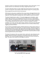
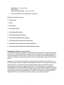
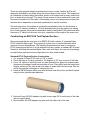
EZ675-5KM
Model Rocket Altimeter
User’s Manual
© Mike Dorffler
2418 Greenway Circle
Canon City, Colorado 81212
USA
[email protected]
1
Altitude Measurement
The EZ675-5KM altimeter determines peak altitude reached by comparing the lowest
barometric pressure measured during flight to the launch site barometric pressure.
Atmospheric pressure decreases as altitude increases. The software algorithm within the
microprocessor constantly samples the atmospheric pressure as the rocket ascends. A
change from decreasing to increasing pressure indicates that a peak in altitude has been
reached and the rocket is then descending. The two barometric pressures are then
mathematically translated to altitude in feet. The altitude at the launch site is subtracted
from the maximum altitude, and the difference is reported as the flight altitude reached.
The mathematical routines used in the EZ675-5K code to first measure and then convert
atmospheric pressure to altitude are quite sophisticated and lengthy. First, the Microchip
microprocessor code algorithm measures the output voltage of the MPXH6115 pressure
sensor using a 12-Bit A/D (Analog to Digital) converter. The A/D count is then converted
to a kPa value X 100. The altitude is then computed using the kPa value;
As used in the EZ675-5K code;
kPa = ((A/D count * 2713) / 1000) + 1055
Example using the 12-Bit A/D count of 3234 retrieved using EZ675-5K code;
kPa = ((3234 * 2713) / 1000) + 1055 = 9828 (98.28)
Compare to kPa calculated from Motorola MPXH6115 specification;
kPa = ((3234 / 4096) + 0.095) / 0.009 = 98.28
Altitude is computed within the EZ675-5K code using the accepted NOAA equation;
Altitude in feet = (1-(kPa/101.325)^0.190284)*145366.45
Altitude for a kPa of 98.28 = 840.6 feet
If we use 2 consecutive 12-Bit A/D counts we can compute the typical resolution using the
algorithms used in the EZ675-5K code;
A/D Count = 2947 = 90.50kPa = 3092 feet
A/D Count = 2948 = 90.52kPa = 3084 feet
Resolution = 8 feet per A/D Count @ ~3000 feet ASL
Altimeter Operation
When the altimeter is first turned on, the altitude reached in the previous flight is retrieved
from the internal EEPROM memory and reported twice. The altitude was stored in the
internal EEPROM as soon as the value was calculated during the flight. This feature is
2
intended to preserve the flight result if the battery dislodges upon a hard landing, or if the
altimeter cannot be recovered before the battery voltage drops below 6 volts.
The ground elevation pressure is then sampled each second during a 16 second wait
period. A running total is accumulated and kept with each sample. The resulting total is
then averaged and saved as the launch site pressure.
With the launch site pressure established, the microprocessor code algorithm then looks
for a sudden decrease in pressure equal to an increase in altitude of 100 feet (30 meters).
When the 100-foot threshold is exceeded, the code is satisfied a launch has occurred.
The launch threshold test is made at 1.5 second intervals and is indicated by a short
audible ‘beep’. Note that it is not necessary that the EZ675-5K be in its final installed
position inside the rocket payload section prior to launch for the launch detect testing to
work correctly. The precision pressure sensor will always correctly measure whether the
100 foot altitude threshold has been reached. The user can complete the altimeter
installation in the rocket, prep the model for flight, install the model on the pad, and attach
the ignition clips to the igniter, and then proceed with launch countdown without falsely
triggering the threshold detect.
Once the 100-foot threshold has been exceeded after launch, the barometric pressure is
continuously sampled at 100 millisecond (1/10 second) intervals. Because the pressure
decreases as the rocket ascends, each reading will be less than the previous reading. As
the rocket slows and approaches peak altitude, the pressure differences begin to diminish
and eventually reach zero. Peak altitude is determined when the present pressure sample
becomes greater than the previous sample.
The launch site pressure is then converted to feet as well as the value detected at peak
altitude. The ground altitude is subtracted from the peak altitude and is stored in the
EEPROM. The circuitry then begins beeping out this value as the altitude reached this
flight. The beep-out will continue until the battery is removed.
The Top Side EZ675-5K Components
3
Power For The Altimeter
The EZ675-5K altimeter is powered by a standard 12 volt “N” size remote battery.
Appropriate part numbers are Duracell MN21/23, GP A23, Energizer A23, and Radio
Shack 23-144. Please do not attempt to use any other type of battery with the EZ675-5K
altimeter.
We hope the user will always install the battery correctly. If however it is inadvertently
installed backwards, a reverse protection diode is included in the circuitry so that the unit
will not be harmed. Some A23 manufacturers use a black plastic disk at the negative end,
and a red disk for the positive end. All manufacturers mark the polarities on the exterior of
the battery. Always be careful to install the battery with the negative end against the
battery holder spring.
To install the battery Hold the altimeter on its edges with the thumb and fore finger of one hand. Push the
negative end of the battery into the battery holder and against the spring. Use the end of
your other thumb to apply pressure on the positive end of the battery to compress the
spring, and then rock the battery into the proper holder position.
To remove the battery Use your thumbnail to grip the edge of positive battery end. Apply downward pressure on
the battery and then rock it out of the holder.
Always remove the battery from the holder after each flight. This is to both preserve
battery life, and to keep the molded battery holder from being deformed over time.
Leaving the battery in place and using a small insulator inserted at either battery end as a
‘switch’ is not recommended.
Battery Life A cautionary note regarding the A23 battery; The EZ675-5K draws a continuous 6 ma of
current. This translates to roughly 8 hours of continuous use from a fresh battery.
Assuming a span of 30 minutes of use from the point the battery is installed, the altimeter
is flown and recovered and the battery removed, the battery will provide 16 flights of use.
Shorter use times will yield a greater number of flights per battery. If in doubt whether the
battery has adequate power remaining for another flight, measure the voltage with the
battery in place. If the voltage is greater than 7.0 volts, the battery is good to use.
Battery and Altimeter Storage We recommend that both the altimeter and battery be physically protected from damage
when not in use. One simple method is to remove the battery and store battery and
altimeter in separate plastic pill bottles. Screw-cap are better than snap-lids for this
purpose. Use a length of bubble wrap around each in their respective bottles for damage
protection during transport in a flight box. Do not use a ‘soft’ material for wrapping around
the altimeter. Loose particles of paper, foam, and the like can separate and enter the
pressure sensor port causing potential damage.
4
General Operation Notes
How the Altitude Is Reported Pre-Loaded Count___________________
Your unit has been shipped with a pre-loaded altitude achieved during the final checkout.
That value is written above, and is saved in the EEPROM memory. As previously noted,
this value will be beeped out twice the first time the altimeter is powered up. This ‘practice’
value allows the user to familiarize himself with the way the audible count sounds out the
altitude. The battery can be removed and re-installed as many times as the user wishes to
hear the count. This count will remain in memory serving as the previous flight altitude
until the altimeter is flown. Just remember to wait about 10 seconds between removing
the battery and re-installing it during each practice run.
Always remember that the code is written so that the battery can be removed immediately
after the saved altitude is read out. It is not necessary to wait though the total pre-launch
sequence to remove the battery to replay the count.
The same method for hearing the stored flight altitude count is true after any flight. In the
event the user has difficulty reading the stored altitude, simply remove the battery, wait
about 10 seconds, and re-install the battery. The altimeter will re-start, and the altitude will
be sounded out twice more. Again, this can be repeated as many times as desired as the
stored altitude will only change after the completion of a new flight.
How the Altitude is reported by the Audio Transducer The individual digits of the flight altitude result are always reported in the same manner. A
long low transducer tone indicates the sequence start. The individual numbers are then
reported beginning with the first of a maximum of 5 digits. A flight to 367 feet for example,
will report only these 3 digits. A flight to 2,432 feet will report 4 digits, and a flight to 11,765
feet will report 5 digits. If the EZ675-5K has been built for Metric operation, the maximum
number of digits will be 4. A short pause occurs between digits to isolate them audibly
from one another.
Any leading zeros are not reported. The 367 foot flight example will begin with the 3, or
‘hundreds’ digit, not with 2 zeros for the missing ‘ten-thousands’ or ‘thousands’. The 2,432
example will begin with the 2 at the ‘thousands’ digit, and the 11,765 feet example will
begin with the first 1 at the ‘ten-thousand’ digit.
As an example, a measured altitude of 1024 will be reported as follows:
Long low tone beep – Sequence Start
Silent Pause
Beep - (1) thousands of feet
Silent Pause
Beeeeeeep – (0) hundreds of feet
Silent Pause
5
Beep-Beep – (2) tens of feet
Silent Pause
Beep-Beep-Beep-Beep – (4) ones of feet
Wait 5 seconds then the sequence is repeated Digits are reported simply as:
0 -- Beeeeeeep
1 – Beep
2 – Beep-Beep
3 – Beep-Beep-Beep
4 – Beep-Beep-Beep-Beep
5 – Beep-Beep-Beep-Beep-Beep
6 – Beep-Beep-Beep-Beep-Beep-Beep
7 -- Beep-Beep-Beep-Beep-Beep-Beep-Beep
8 -- Beep-Beep-Beep-Beep-Beep-Beep-Beep-Beep
9 -- Beep-Beep-Beep-Beep-Beep-Beep-Beep-Beep-Beep
Installing the Altimeter in your Rocket The EZ675-5K needs to be placed in a payload section forward of the main power section
of your rocket. The payload section must be built so that the interior is totally isolated from
any ejection gases from the motor. Failure to do so may allow the heat and pressure of
the ejection charge to penetrate the payload section, and damage or destroy the pressure
sensor.
Remember, the key design element for proper altimeter operation is the ability for it to
‘breath’ properly. The code samples the atmospheric pressure 10 times per second as the
rocket ascends. The payload section must be properly vented to allow the internal
payload section pressure to rapidly equalize to the outside pressure. The way this is
accomplished is to vent the payload section with an array of equally spaced through-holes.
The holes allow a quick flow of pressure differences to either enter or escape the payload
section during rocket ascent and descent. The EZ675-5K will fail to properly measure
flight altitude if it cannot quickly track the changes in atmospheric pressure.
6
There are other payload design considerations to bear in mind. Laminar air flow will
always be disturbed by any break along the exterior shape of the rocket. This means that
air turbulence is induced along the exterior surface of a model rocket at every radial body
joint, or break along its length. The worst of these occurs at the joint where the nose cone
fits into the forward end of the rocket. Unfortunately, this is very nearly where we place the
altimeter that is dependant on pressure equalization to function correctly.
The work-around for this problem is to place the equalization holes for the altimeter a
minimum of 3 calibers (a caliber is 1.0 body diameter) back from the nose cone mating
joint. As an example, the pressure equalization holes for an Estes BT-50 tube should be a
minimum of 3” back from the nose cone joint, regardless of the length of the nose cone.
Constructing an EZ675-5K Test Payload Section –
We recommend that the new user of an EZ675-5K build a simple ‘C’-powered Estes
BT-50 sized test flight model. The purpose is to learn how to use the altimeter with a
minimum of motor expenditures. The following illustrations show how to construct a
BT-50 sized payload section to fly the altimeter with any number of standard BT-50 sized
Estes kits, including the standard Alpha. After a few test flights, the user can then design
and build other payload section configurations for other sized models.
Standard BT-50 Payload Section Construction –
1. Cut a length of Estes BT-20 tube to 2.78” in length.
2. Pierce the tube in 3 places, spaced at 120 degrees, 0.35” from one end of the tube.
3. Use a 1/8” drill bit to carefully round out each pierced hole. Apply thin cyanoacrylate
glue around the edge of each hole and allow to cure. Then lightly sand the interior and
exterior surfaces of the tube at the hole edges to make them nice and crisp. Run the
drill bit through the holes again to remove any fuzz.
4. Insert an EB-20A engine block even with the same end of the tube, and bond in place
using the thin cyanoacrylate adhesive.
5. Bond an Estes AR-2050 adapter ring with its rear edge 3/8” from the end of the tube
with the engine block.
6. Bond another AR-2050 adapter ring even with the other end of the tube.
7
7. The base body tube fitting for this payload section uses one of the 2 needed Estes
PIN-50Y plastic nose cone inserts. The fit will be too loose in the BT-50 section
without modification. First cut a ½” length of BT-50, then cut out a 1/8” wide section on
one side. This will make a spacer that corrects the loose fit of the PIN-50Y.
8. Wrap and bond the slit tube around one of the PIN-50Y adapters. Make sure the
edges of both parts match.
9. Cut a disk of 1/16” plywood or very hard balsa to make a slide fit in a BT-50 tube. This
will be the ejection charge gas bulkhead.
10. Lightly sand the open edge of the PIN-50Y and spacer tube. Then carefully align and
bond the ply disk to this edge.
11. Apply thin cyanoacrylate to the exposed face of the disk to seal it against gas flow.
12. Cut a 4.0” length of BT-50 tubing. Pierce the tube in 3 places, spaced at 120 degrees,
0.94” from one end of the tube.
13. As with the BT-20 tube, use a 1/8” drill bit to carefully round out each pierced hole.
Again apply thin cyanoacrylate around the edge of each hole and allow to cure. Then
lightly sand the interior and exterior surfaces of the tube at the hole edges to make
them nice and crisp. Run the drill bit through the holes again to remove any fuzz.
14. Bond the base adapter assembly inside this end of the payload section with the holes.
8
15. Remove the attachment loop from the remaining PIN-50Y adapter. Lightly sand the
face of the part smooth, and then bond the adapter inside the base of the PNC-50Y
nose cone.
This completes the assembly steps for the altimeter test payload section.
Test fit the inner BT-20 altimeter holder tube into the BT-50 tube. Insert the EZ675-5K into
the holder tube with the transducer at the lower adapter end.
Always remember to install the altimeter in the payload section with the pressure sensor
at the forward end.
The payload section is designed so that the bottom printed circuit board edge stops at the
edge of the EB-20A engine block. Test fit the nose cone into the forward open end of the
tube. The fit must be tight so the altimeter isn’t ejected during deceleration or at the shock
of parachute opening. Use layers of masking tape around the nose cone adapter to
achieve the needed tight fit.
Phantom View Of EZ675-5K Inside Payload Section
9
You can paint the exterior of the completed payload section almost any way you like.
However, do NOT paint it black or other dark color. Dark colors will heat the interior of the
payload in sunlight and this is to always be avoided.
In use, make sure the pressure vent ports are never obstructed in any way. Keep your
back toward the sun when handling and inserting the EZ675-5K in the payload section.
Direct sunlight can adversely affect the way the pressure sensor operates, and is why the
suggested payload section is designed to block it.
When planning other payload section designs, always try to follow the ‘3 X 3’ rule – place
three equally spaced holes in the body section placed at a minimum of 3 calibers aft of the
nose cone / body tube joint. The use of the 3 holes helps to eliminate any false threshold
triggering during handling or on the launch pad waiting for launch. They also help
minimize any pressure variations on all sides at any orientation of the rocket during flight.
Always make sure the vent holes have clean and smooth edges on any payload section
you build. Use the technique described in the payload section construction above for
piercing, drilling, and sealing the hole’s edges. Try to make the diameter of the holes
approximately 8% - 10% of the diameter of the payload section.
Operation of the EZ675-5K Altimeter
The user should always follow a specific order of flight preparation sequence when using
the EZ675-5K. Take a few more moments to double check each step before launch.
Otherwise, the altitude readings may be incorrect.
1. Start by removing the nose cone or forward closure from the altimeter payload section.
Also remove the altimeter holding fixture from within the payload section if used.
2. Prepare the rocket for flight in normal fashion. Select and install the motor with igniter.
Insert the proper amount of flameproof wadding. Roll, fold and insert the parachute(s),
then temporarily mate the empty payload section to the main power section.
3. Insert the 12 volt A23 battery to turn the altimeter ON. The altitude of the previous flight
will be reported two times. This indicates the altimeter is operating correctly. Once this is
confirmed the user can begin the process of installing the altimeter in the payload section.
4. Use caution not to install the altimeter too quickly. The air in the payload section must
be allowed to exit freely to prevent false launch site readings as the altimeter is slides into
position. This can occur if altimeter installation spans the silent 15 second launch site
pressure measuring mode.
5. When the 15 second period ends the altimeter will indicate readiness with a short
“beep” repeated every 1.5 seconds. At this point the rocket is ready to launch.
10
6. Reinstall the nose cone or forward payload section closure. Place the rocket on the
launch pad, attach the igniter power leads, and prepare for launch in the typical fashion.
When the rocket is recovered after flight, the EZ675-5K will be reporting the peak altitude
attained. Since this reading is saved in memory, there is no rush to remove the altimeter
from the payload section to hear and record the altimeter reading. If desired, the user can
open the payload section and remove the battery to hear the altitude at a later time.
Otherwise, listen and record the altitude reached as displayed by the transducer.
Reminders:
o
o
o
o
o
o
o
o
o
Avoid touching the circuit board traces or components when powered.
Avoid allowing any metallic object to touch the altimeter when powered.
Protect the altimeter from severe temperature fluctuations before operation.
Avoid strong wind gusts flowing past the altimeter payload section prior to launch.
Always protect the altimeter pressure sensor from direct sunlight.
Do not allow the altimeter to come in contact with water.
Replace the battery when the voltage falls to under 7.0 volts.
Protect the pressure sensor from excessive pressures.
Always follow proper operational sequencing as listed in preflight checklist.
Warranty
The purchase of an EZ675-5K altimeter includes a 90 day warranty against defects in
parts and workmanship. Your EZ675-5K will be replaced if it should fail in use during this
time period. This warranty applies only to the altimeter, and does not cover any rocket,
rocket motors, or any other part, parts, and any other equipment associated with the use
of the EZ675-5K altimeter.
Not covered by this warranty is damage due to misuse, mechanical or circuitry alterations,
and failures caused by use outside of the recommended operating conditions. Any
damage to the pressure sensor caused by diaphragm puncture or pressure sensor
damage caused by ejection charge pressure or heat, are not covered under this warranty.
Liability
This product has been designed and constructed with the highest quality materials. As the
installation, setup, preparation, maintenance, and use of this product is beyond the
control of the manufacturer, the purchaser and user accept sole responsibility for the safe
and proper use of this product.
The principals, employees, and vendors of the manufacturer shall not be held liable for
any damage or claims resulting from any application of this product. If the purchaser and
user are not confident in their ability to use the product in a safe manner it should be
returned to the point of purchase immediately. Any use of this product signifies
acceptance of the above terms by the purchaser and user.
11