1
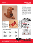
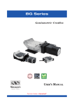
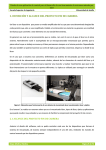
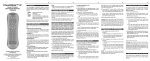
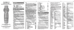
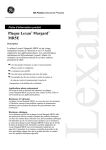
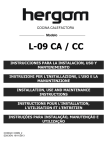
RTM Series
High-Performance Annular Rotation Stages
High-Performance Annular Rotation Stages
RTM Series
1.0 Introduction
This manual provides operating instructions for the rotation stage that you
have purchased in the RTM Series:
• RTMPP
• RTMPE
• RTMCCHL
• RTMCC
• RTMMS
It indicates equally minimum maintenance operations, useful to a good
equipment functioning.
RECOMMANDATION
We recommend you to read attentively the chapter “Connection to electronics” before RTM stage using.
1
EDH0160En1011 – 07/97
RTM Series
High-Performance Annular Rotation Stages
2.0 Description
RTM Series rotation stages offer high-precision angular positioning accuracy with high load-carrying capacity and a compact, annular design. Precise
rotation is ensured by a precision-ground, hardened worm and gear drive
(worm gear ratio: 1/180), which provides smooth motion. A double-row of
pre-loaded, recirculating ball-bearings supports the rotating platform,
adding the benefits of high load capacity and excellent rigidity.
All RTM stages are equipped with mechanical limit switches (±165° for
RTM80 and RTM120, ±170° for other sizes) and a home position allows the
stage to be returned to a reference origin position.
Position measuring is performed with a 2000 pts/rev. encoder, integral with
the motor shaft.
All RTM Series stages are equipped with a knurled knob for a manual control.
0
31
32
0
33
0
While all featuring 0.001 deg angular resolution, the modular design of RTM
stages brings you the flexibility to choose the drive configuration that best
matches your specific application requirements: manual, DC motor or stepper motor driven versions, with mini-step or full-step drive options, highertorque 20 °/sec versions.
For optimum positioning performance and seamless compatibility, we
recommend our MotionMaster family of motion controllers for these
devices. The RTM Series stages are supplied with a 3-meter cable for
connection to the MotionMaster controllers.
EDH0160En1011 – 07/97
2
RTM Series
High-Performance Annular Rotation Stages
3.0 Characteristics
3.1
Position Precision
Specifications of our products are established in reference to ISO 230 norm
part II “Determination of the position, precision and repetability of the
machine tools with CNC”.
This norm gives definition of position uncertainty which depends of the 3
following quantitites:
Position Error
Difference of postion between ideal position and real position.
Position Repetabilty (Repetability)
Variation between ideal postion and real position approached “n” times.
Reversal Error (Hysteresis)
Difference of position dued to direction of approach of ideal position.
Position uncertainty depends of 2 quantities:
• The first one is dued to service condition (temperature, position of
article on the carriage) and to uncertainty on screw pitch.
• The second one is dued to conception of our positionning stages.
The first quantity varies on a linear way with travel. It can be compensated
by mean of controller.
The second term is intrinsic to our stages ans cannot be compensated. We
call it on axis accuracy.
NOTE
In this manual we will use: On axis accuracy, repetability, Hysteresis.
Those definitions are valid for linear stages as well as for rotary stages.
The controls of on axis accuracy, repetability, and reversal error are made systematically with our test equipement in an air-conditioned room (20 °C ±1 °C).
Linear stages are controlled with laser interferometry (Hewlett-Packard,
resolution 10 nm).
Rotary stages are controlled with precision optical encoder (Heidenhain,
resolution 5/10000°).
For each stage a linear cycle with 21 measures on travel and 4 cycles in
each direction gives a total of 164 points.
3
EDH0160En1011 – 07/97
RTM Series
High-Performance Annular Rotation Stages
3.2
Mechanical Specifications Definitions
Sensitivity (unidirectional)
Minimum motion that a stage can make. Our stages and our kinematic
chain are conceived on such a way that sensitivity is better than resolution
of encoders (tipically 1 µm, 0.1 µm or 1/1000 deg).
Resolution
The smallest motion a metrology fixed to the stage can measure.
For manual stages, resolution is given by graduation on micrometer.
For motorized stages, resolution is given by reading of encoder information, as well for translation stage as for rotation stages.
Concentricity
Displacement of the geometric center of a rotation stage from the rotation
axis in the plan defined by bearings.
Wobble
Tilt of rotation axis during rotation of a stage.
3.3
Mechanical Specifications
Diameters
(mm) 80; 120; 160; 240; 350
Drive
Stepper
(PP; PE)
DC
(CCHL; CC)
Manual
(MS)
0.015
(RTM80)
On Axis Accuracy
(°)
0.010
(RTM120 to RTM350)
Repeatability
(°) 0.002
Hysteresis
(°) 0.006
(RTM80)
0.004
(RTM120 to RTM350)
50
(RTM80)
(RTM120; RTM160)
Wobble
(µrad) 40
60
(RTM240; RTM350)
Concentricity
(µm) 5
3.4
Load Specifications Definitions
Load Capacity (Cz)
Maximum load a stage can move.
This value is given with speed and accelaration specified for each stage,
and with a load perpendicalar to bearings.
Off-Centerd Load (Q)
Maximum cantiliver-load a stage can move: Q ≤ Cz / (1 + D/a)
D:
Cantilever distance.
a:
Construction parameter.
On Axis Load Capacity (Cx)
Direct load capacity on axis with specified speed and acceleration.
EDH0160En1011 – 07/97
4
RTM Series
High-Performance Annular Rotation Stages
Angular stiffness (kα)
This is dued to stage cosntruction.
We specify this stiffness around X axis (kαx) and around Y axis (kαy) for
translation, and perpendicular to rotatio axis for rotary stages. It allows
determination of stages deformations dued to off-centered load.
Nominal Torque (Mz)
Maximum torque a rotary stage can supply. This value is specific to the
motor used. So we specify it for each kind of motor.
When rotary stages are used in vertical, the load moment is created by an
off-centered load.
Maximum inertia
Maximum inertia that a stage can move around its rotation axis.
3.5
Off-center Load Characteristics
RTM80
RTM120
Cz
(N) 600
1200
a
(mm)
30
40
kα
(µrad/N.m)
21
3
(PE)
1.8
10
Mz (PP)
(N.m)
1.8
8
(1)
(CC)
1.8
10
1)
RTM80CCHL only.
RTM160
1800
50
2.2
20
14
11
RTM240
2700
70
1.3
24
17
13
RTM350
4200
100
0.5
27
18
14
with:
Z
Q
D
: Off-center load,
Q ≤ Cz / (1 + D/a)
Q
Cz
kα
Mz
3.6
Cz : Normal center load capacity on
bearings
D : Cantilever distance in millimeters
a : Construction parameter
kα
: Transversal stiffness
Mz
: Nominal torque
Motorized Stages Weight
Weights indicated into the below table are average values for stages with
the drive unit.
RTM80
(kg) 1.2
RTM120
(kg) 4.5
RTM160
(kg) 6.5
RTM240
(kg) 10
RTM350
(kg) 16
The weight variation according to the drive unit is not very significant.
5
EDH0160En1011 – 07/97
RTM Series
High-Performance Annular Rotation Stages
4.0 Drives
4.1
Stepper Motor Drive
Stepper-motor-driven stages are offered in two variants:
• One mini-step drive version: RTMPP.
• One full-step version: RTMPE.
RTM120 to 350PE
RTM120 to 350PP
RTM80PE
RTM80PP
Full-Step Drive
Is used for stepper motors, when 1 pulse emmited by electronic corresponds to theoritical physical motion of 1 full step of the motor.
Our full-step stages have one more specification: minimum increment of
kinematic chain equals encoder resolution.
Mini-Step Drive
Is used for stepper motors, when 1 pulse emmited by electronic corresponds to theoritical physical motion of a fraction of a full step of the motor.
For these stages a mini-step equals 1/10 of a full step.
Stepper Motor Performance Specifications
Resolution
Speed
(°)
(°/sec)
RTM80PP
UE41PP
RTM120PP
UE62PP
RTM160PP
0.001
RTM240PP
20
UE63PP
RTM350PP
EDH0160En1011 – 07/97
Motor
6
RTM Series
High-Performance Annular Rotation Stages
Resolution
Speed
(°)
(°/sec)
Motor
RTM80PE
UE31PP
RTM120PE
RTM160PE
0.001
2
UE41PP
RTM240PE
RTM350PE
4.2
DC Motor Drive
Two DC-motor-driven configurations are available:
• One version equipped with a tachometer: RTM80CCHL; RTM120CC;
RTM160CC; RTM240CC; RTM350CC.
• One low-power version: RTM80CC.
RTM120 to 350CC
RTM80CCHL
RTM80CC
DC Motor Performance Specifications
Resolution
Speed
(°)
(°/sec)
Motor
RTM80CCHL
UE404CC
RTM120CC
RTM160CC
0.001
20
UE511CC
RTM240CC
RTM350CC
RTM80CC
4.3
0.001
2.5
UE31CC
Manual Drive
One manual drive version is available, equipped with a rotary encoder:
RTMMS.
Our CV1000 Display Counter permits to read the position.
RTM120 to 350MS
RTM80MS
Manual Performance Specifications
Resolution
Nb
(°)
(°/rev.)
RTMMS
0.001
7
2
EDH0160En1011 – 07/97
RTM Series
High-Performance Annular Rotation Stages
5.0 Motorization
5.1
Motor
UE31PP
UE41PP
UE62PP
UE63PP
Angle by Step
(°)
3.6
1.8
1.8
1.8
Newport Stepper Motor Characteristics
Current
(A)
0.56
1.2
1.8
2.9
5.2
Resistance
(Ω)
7.6
3
2.6
1.16
Inductance
(mH)
8.4
4.3
4.9
2.0
Newport
Utilization
Full-Step
Full-Step or Mini-Step
Mini-Step
Mini-Step
Command Signals for Newport Stepper Motors
Command Signals
UE41PP, UE62PP, UE63PP
Command Signals
UE31PP
1
2
3
1
4
Phase 1
Phase 1
Phase 2
Phase 2
Phase 3
Phase 3
Phase 4
Phase 4
Direction –
Displacement
Direction +
Direction –
2
3
4
Displacement
Direction +
Direction +
EDH0160En1011 – 07/97
8
Direction +
RTM Series
High-Performance Annular Rotation Stages
5.3
Motor
UE31CC
UE404CC
UE511CC
Newport DC Motor Characteristics
Mechanical Power
(W)
2.53
40
110
5.4
Nominal Voltage
(V)
24
75
75
Armature Resistance
(Ω)
57
18.6
5.1
Tachometer
(V/Krpm)
–
3 (±10%)
7 (±10%)
Command Signals for Newport DC Motors
+ Motor
+ Tacho Generator
+V
+ Motor
+ Tacho Generator
+V
– Motor
– Tacho Generator
–V
– Motor
– Tacho Generator
–V
Displacement
Direction +
Direction –
Displacement
Direction +
Direction +
In the above drawings, + Motor signal is referred to – Motor signal, + Tacho
Generator signal is referred to – Tacho Generator signal.
1 When the stage moves in + Direction, the + Motor voltage is higher than
– Motor voltage, and + Tacho Generator voltage is higher than – Tacho
Generator voltage.
2 When the stage moves in – Direction, the + Motor voltage is lower than
– Motor voltage, and + Tacho Generator voltage is lower than – Tacho
Generator voltage.
5.5
Sensors Position
Home Position
– EOR Limit
+ EOR Limit
Mechanical
Zero
Index Pulse
Index Pulse
Stage Travel Range
Displacement
Direction +
End-of-Run and Mechanical Zero are “Open Collector” type output signals.
Their use needs a pull-up resistance connected to the power supply (generally the power supply of the board where signals are sent).
9
EDH0160En1011 – 07/97
RTM Series
High-Performance Annular Rotation Stages
Newport
Stage
User
Output Signal
User Power Supply
(ex.: 4.7 kΩ)
Pin #22
0 V Encoders and Sensors
+5 V Power
Pin #21
Index Pulse and Index Pulse are “differential pair” type output signals.
Using these signals permits a high immunity to noise. Emission circuits
generally used by Newport are 26LS31 or MC3487. Reception circuits to use
are 26LS32 or MC3486.
5.6
Feedback Signals Position
1
Encoder
Phase A
Encoder
Phase A
Encoder
Phase B
Encoder
Phase B
2
3
4
1
1
Encoder
Phase A
0
1
Encoder
Phase A
0
1
Encoder
Phase B
0
1
Encoder
Phase B
0
Displacement
Direction +
2
3
4
1
0
1
0
1
0
1
0
Direction –
Displacement
Direction +
Direction +
The incremental sensor operates following the photoelectric measurement
principle, with a disk including slides. When the sensor shaft turns, the sensor generates square signals in quadrature, sent to pins #19, #20, #23 and
#24 of the 25-pin Sub-D connector.
Newport
Stage
User
Encoder Phase A
Pin #19
Encoder Phase A
Pin #23
Encoder Phase B
Pin #20
Encoder Phase B
Pin #24
Pin #21
Pin #22
Output Signals
+5 V Encoders and Sensors
0 V Power
Encoders are “differential pair” type output signals. Using these signals permits a high immunity to noise. Emission circuits generally used by Newport
are 26LS31 or MC3487. Reception circuits to use are 26LS32 or MC3486.
EDH0160En1011 – 07/97
10
RTM Series
High-Performance Annular Rotation Stages
5.7
Pinouts
14
25
1
13
The 25-pin Sub-D connection for each RTM stage is given in the following
table:
UE31PP & UE41PP:
UE31CC:
UE404CC:
Manual:
RTMPE
RTM80CC
RTM80CCHL
RTMMS
UE41PP; UE62PP; UE63PP:
UE511CC:
RTMPP
RTM120CC to RTM350CC
1
Phase 1
N.C.
+ Tacho Generator
N.C.
2
Phase 1
N.C.
+ Tacho Generator
N.C.
3
Phase 2
N.C.
– Tacho Generator
N.C.
4
Phase 2
N.C.
– Tacho Generator
N.C.
5
Phase 3
+ Motor
+ Motor
N.C.
6
Phase 3
+ Motor
+ Motor
N.C.
7
Phase 4
– Motor
– Motor
N.C.
8
Phase 4
– Motor
– Motor
N.C.
9
Common phase 3-4
N.C.
N.C.
N.C.
10
N.C.
N.C.
N.C.
N.C.
11
Common phase 1-2
N.C.
N.C.
N.C.
12
N.C.
N.C.
N.C.
N.C.
13
Mechanical Zero
Mechanical Zero
Mechanical Zero
Mechanical Zero
14
Shield Ground
Shield Ground
Shield Ground
Shield Ground
15
Encoder Index Pulse I
Encoder Index Pulse I
Encoder Index Pulse I
Encoder Index Pulse I
16
0 V logic
0 V logic
0 V logic
0 V logic
17
+ End-of-Run
+ End-of-Run
+ End-of-Run
+ End-of-Run
18
– End-of-Run
– End-of-Run
– End-of-Run
– End-of-Run
19
Encoder Phase A
Encoder Phase A
Encoder Phase A
Encoder Phase A
20
Encoder Phase B
Encoder Phase B
Encoder Phase B
Encoder Phase B
21
Encoder Power: +5 V
Encoder Power: +5 V
Encoder Power: +5 V
Encoder Power: +5 V
22
0 V Encoder
0 V Encoder
0 V Encoder
0 V Encoder
23
Encoder Phase /A
Encoder Phase /A
Encoder Phase /A
Encoder Phase /A
24
Encoder Phase /B
Encoder Phase /B
Encoder Phase /B
Encoder Phase /B
25
Encoder Index Pulse /I
Encoder Index Pulse /I
Encoder Index Pulse /I
Encoder Index Pulse /I
11
EDH0160En1011 – 07/97
RTM Series
High-Performance Annular Rotation Stages
6.0 Connection to a Newport Electronics
6.1
Warnings on electronic units
Electronic units are intended for use by qualified personnel who recognize
shock hazards and are familiar with safety precautions required to avoid
possible injury. Read the electronics manual carefully before operating the
instrument and heed all written warnings and cautions.
WARNING
Disconnect the power plug under the following circumstances:
• If the power cord or any attached cables are frayed or damaged in
any way.
• If the power plug is damaged in any way.
• If the unit is exposed to rain, excessive moisture, or liquids are spilled
on the unit.
• If the unit has been dropped or the case is damaged.
• If you suspect service or repair is required.
• Whenever you clean the case.
CAUTION
To protect the unit from damage, be sure to:
• Keep all air vents free of dirt and dust.
• Keep all liquids away from the unit.
• Do not expose the unit to excessive moisture (>85% humidity).
• Read this manual before using the unit for the first time.
WARNING
All attachment plug receptacles in the vicinity of this unit are to be of the
grounding type and properly polarized.
Contact your electrician to check your receptacles.
WARNING
This product is equipped with a 3-wire grounding type plug.
Any interruption of the grounding connection can create an electric
shock hazard.
If you are unable to insert the plug into your wall plug receptacle,
contact your electrician to perform the necessary alterations to assure
that the green (green-yellow) wire is attached to earth ground.
WARNING
This product operates with voltages that can be lethal.
Pushing objects of any kind into cabinet slots or holes, or spilling any
liquid on the product, may touch hazardous voltage points or short out
parts.
EDH0160En1011 – 07/97
12
RTM Series
High-Performance Annular Rotation Stages
Connection
On each stage is represented a label which indicates its name, its serial
number and the motor it is equipped (ex.: UE31PP).
RTM80PE
ENCODER:5V
Stepper Motor
S/N#
MOTOR:UE31PP
U=30VDC I=1A
WARNING
Before to begin any connection, make sure that the name of the motor
indicated on the stage corresponds to the name of the motor indicated
on the driver module.
WARNING
Always turn power OFF electronics units to link up before to connect
them stages.
Stages may be connected to the rear panel motor connectors labeled
“Motor…” any time prior to power-up with the supplied cable assemblies.
WARNING
Damage to stage may occur if the stage is not the same type as shown on
driver label located near the stage interface connector (see drawing
below).
Check that the option number specified on this label correspond to the
number indicated in the driver module options table for your stage (see
next page).
To protect the
Stage and/or
Driver Module
during
Fault Condition
!
STEPPER MOTOR
OPTIONS # 05/45/46
UE31PE
U = 30VDC I = 0.4A
Encoder Supply 5VDC
Do not connect or
disconnect while
power is applied
FUSES
F0.5A/250V
!
CAUTION
Made in
France
Do not connect or
disconnect while
power is applied
Remote Controle Interface
25-pin male connector
REMOTE
CONTROLE
Stage Interface
25-pin female connector
Stage dependent
CAUTION
Made in
France
STEPPER MOTOR
FUSES
F0.5A/250V
OPTIONS # 05/45/46
UE31PE
U = 30V I = 0.4A
Encoder Supply5V≈
6.2
REMOTE
CONTROL
WARNING
Do not mistake the 25-pin Remote Control Interface Connector with one
of the Stage Connector Interface on MD1000 and MM2500 units.
13
EDH0160En1011 – 07/97
RTM Series
High-Performance Annular Rotation Stages
6.3
Driver Module Options
Driver modules for our MotionMaster (MM) Series controllers are available
for each of the RTM Series stages.
They are referenced as 2-digit coded options to be used in the motion
controller part number and are listed in the following table.
MM2000
MD1000
MM2500
MM3000
MM4005
Electronics:
Display +
Manual Control:
Without
With
Without
With
(1)
Display +
Keyboard
RTM80PP
–
12
51
12
51
12
12
RTM120PP
–
15
55
15
55
14
15
RTM160 à 350PP
–
1A
5A
1A
5A
08
1A
RTM80PE
–
05
46
05
46
03
05
RTM120 à 350PE
–
1H
5J
1H
5J
05
1H
RTM80CCHL
–
72
92
–
–
72
7G
RTM120 à 350CC
–
79
96
–
–
76
7H
RTM80CC
05
64
83
–
–
63
64
1)
6.4
Front panel with keypad and display is ordered as a chassis option.
Cables
All our stages are delivered with a 3-meter cable with 25-pin Sub-D connector.
So they can be directly connected to our controllers/drivers of MM series.
Locking
Knobs
Ø 10.3
25-Pin
Sub-D
54
Disconnected: 59
Statical: 104
Dynamical: 166
WARNING
These cables are shielded correctly. For a correct operating, make sure
for connectors locking (grounds continuity provided by cables).
For long distance applications, higher lengths cables are available in standard.
Electronic cable from MM controllers/drivers to stages with 25-pin Sub-D
connector are available in 5 m or 10 m length.
EDH0160En1011 – 07/97
14
RTM Series
High-Performance Annular Rotation Stages
WARNING
Cables creep into a typical industrial environment: separtes motor cables
and power supply cables. Motor cables must be a specific csbles creep.
Electronic components included in our stages need 5V regulated voltage.
If you use cables longer than 3 m, you have to add a voltage regulator.
25-Pin Sub-D
Male
25-Pin Sub-D
54
Female
62
This regulator with 25-pin Sub-D connector has to be fixed on the stage.
Others lengths (up tu 25 m) are available on request.
Please contact your sales representative.
A Sub-D 25M/Sub-D 25F cable is necessary to connect a stage from a MM2000
board, via a UIB box.
7.0 Connection to other electronics
AVERTISSEMENT
The responsibility of Newport will not be able to be committed in case of
bad functioning or damage of a stage used with an electronics non provided by Newport.
15
EDH0160En1011 – 07/97
RTM Series
High-Performance Annular Rotation Stages
8.0 Mounting
WARNING
Before to use a RTM stage, it is imperative to fix it:
• directly on a rectified working surface,
• on an other stage, directly or with a mounting interface.
but in no case, the stage has to remain without fastening.
It is equally necessary to fasten the device to move on the carriage.
CAUTION
The working surface flatness directly influences on stages accuracy and
performances.
9.0 Dimensions
9.1
RTM80
H max.
13.5
4 holes M4 thd on
11
55 x 17.5
95
170
180
190
Ø 80
L
Both sides:
4 holes M3 thd at 90° on Ø 57
Depth: 4
160
38
200
0
15
21
0
22
0
14
0
0
250
110
0
100
260
90
270
Ø 62
25-pin Sub-D connector
12
24
0
0
13
23
Ø 50 H7
80
280
70
290
60
0
30
50
0
31
32
40
0
62.5
33
30
0
340
350
0
10
20
Model shown: RTM80PP.
Dimensions in millimeters.
L
80.5
129
141
106.5
90.5
RTM80PP
RTM80PE
RTM80CCHL
RTM80CC
RTM80MS
EDH0160En1011 – 07/97
16
H
42
32
48.5
32
32
RTM Series
High-Performance Annular Rotation Stages
9.2
RTM120
60
max.
20.5
180
Ø 120
L
170
21
80 x 28.5
190
200
160
21
0
0
15
22
0
0
0
250
110
24
0
0
12
0
13
23
100
Ø 78 H7
260
90
270
Ø 94
Both sides:
4 holes M4 thd at 90° on Ø 87.5
Depth: 6
14
53
4 holes M6 thd on
Depth: 10
144.2
80
280
70
290
60
0
30
50
0
31
32
92.5
40
0
33
0
30
340
20
350
0
10
Model shown: RTM120CC.
Dimensions in millimeters.
L
121
129.5
192
143.4
RTM120PP
RTM120PE
RTM120CC
RTM120MS
9.3
RTM160
60
max.
20.5
180
Ø 160
170
21
90 x 28.5
L
160
53
4 holes M6 thd on
Depth: 10
158.2
190
200
21
0
15
0
22
14
0
0
0
13
23
0
0
250
11 0
0
12
24
100
Ø 110 H7
260
90
270
Ø 131
80
280
70
290
0
60
30
1
0
50
31
114.75
Both sides:
6 holes M5 thd at 60° on Ø 120
depth: 7
32
40
0
33
30
0
340
350
20
0
10
Model shown: RTM160PP.
Dimensions in millimeters.
L
146.5
129.5
192
143.4
RTM160PP
RTM160PE
RTM160CC
RTM160MS
17
EDH0160En1011 – 07/97
RTM Series
High-Performance Annular Rotation Stages
9.4
RTM240
60
max.
20.5
180
21
140 x 28.5
L
170
55
4 holes M6 thd on
Depth: 10
206,2
190
200
160
Ø 240
21
0
15
0
22
0
14
0
0
0
12
0
13
23
24
0
110
260
100
250
Ø 175 H7
90
270
Ø 195
80
280
70
290
0
60
30
50
0
154.75
31
1
Both sides:
6 holes M5 thd at 60° on Ø 187.5
Depth: 7
32
40
0
33
30
0
340
20
350
0
10
Model shown: RTM240PP.
Dimensions in millimeters.
L
146.5
129.5
192
143.4
RTM240PP
RTM240PE
RTM240CC
RTM240MS
EDH0160En1011 – 07/97
18
RTM Series
High-Performance Annular Rotation Stages
9.5
RTM350
60
max.
22.5
4 holes M6 thd on
248.2
180
21
L
170
59
182 x 32 – Depth: 10
190
200
160
21
0
15
0
Ø 350
22
14
0
0
0
0
13
23
0
0
12
24
260
100
250
110
Ø 280 H7
90
270
Ø 310
80
280
70
290
0
60
30
0
50
31
211.75
Both sides:
6 holes M6 thd at 60° on Ø 295
Depth: 7
32
40
0
1
33
30
0
340
20
350
0
10
Model shown: RTM350PP.
Dimensions in millimeters.
L
146.5
129.5
192
143.4
RTM350PP
RTM350PE
RTM350CC
RTM350MS
19
EDH0160En1011 – 07/97
RTM Series
High-Performance Annular Rotation Stages
10.0 Maintenance
10.1
Maintenance
RTM Series stages necessitate no particular maintenance. Nevertheless,
this are precision mechanical device that must be maintained and manipulated with precaution.
PRECAUTIONS
RTM Series stages must operate, or to be stocked in a clean environment,
without dusts, humidity, solvent or other substances.
10.2
Repairing
CAUTION
Never attempt to disassemble an element of the stage that has not been
specified in this manual (base and interface plates).
To disassemble a non specified element can provoke a bad functioning
of the stage.
If you observe a bad functioning of your stage, please contact immediately
your sale representative that will know to indicate you manipulations to
undertake, or instructions to return us the equipment.
CAUTION
All disassembling attempt or repair of stage without authorization will
interrupt your warranty.
10.3
Control
CAUTION
It is recommended to return us your stage every year for a control of its
specifications.
EDH0160En1011 – 07/97
20
Service Form
Your Local Representative
Tel. :
Fax:
Name:
Return Authorization #:
(Please obtain prior to return of item)
Compagny:
Adress:
Date:
Country:
Phone Number:
P.O. Number:
Fax Number:
Item(s) Being Returned:
Model #:
Serial #:
Description:
Reasons of return of goods (please list any specific problems):
21
EDH0160En1011 – 07/97
EDH0160En1011 – 07/97
22
Motorized
Translation &
Rotation Stages
EC Declaration of Conformity
We declare that the accompanying product, identified with the
“ ” mark, meets all relevant requirements of Directive
89/336/EEC for Electro-Magnetic Compatibility.
Compliance was demonstrated to the following specifications:
EMISSION:
Radiated and Conducted Emission per EN 50081-1
“Residential, Commercial and Light Industry” Standard.
IMMUNITY:
Radiated and Conducted Immunity per EN 50082-2
“Industrial” Standard.
Alain DANIELO
VP European Operations
Zone Industrielle
45340 Beaune-la-Rolande, France
RTM High-Performance
Annular Rotation Stages
USER’S MANUAL
RTM Series
High-Performance Annular Rotation Stages
Warranty
Newport Corporation warrants this product to be free from defects in
material and workmanship for a period of 1 year from the date of shipment.
If found to be defective during the warranty period, the product will either
be repaired or replaced at Newport’s option.
To exercise this warranty, write or call your local Newport representative,
or contact Newport headquarters in Irvine, California. You will be given
prompt assistance and return instructions. Send the instrument, transportation prepaid, to the indicated service facility. Repairs will be made and
the instrument returned, transportation prepaid. Repaired products are
warranted for the balance of the original warranty period, or at least 90
days.
Limitation of Warranty
This warranty does not apply to defects resulting from modification or
misuse of any product or part.
CAUTION
Warranty does not aplly to dammages resulting from:
• a bad utilization
– Load on the stage graeter than specified load.
– Carriage speed higher than specified speed.
– Non respected grounds continuity.
¬ Connectors locking.
¬ When the load on the stage represents an electrical risk, inevitably it must be connected to the ground.
– Bad mounting stage or fixing load.
• Modification of the stage or any part.
This warranty is in lieu of all other warranties, expressed or implied, including any implied warranty of merchantability or fitness for a particular use.
Newport Corporation shall not be liable for any indirect, special, or consequential damages.
No part of this manual may be reproduced or copied without the prior written approval of Newport Corporation.
This manual has been provided for informations only and product specifications are subject to change without notice. Any changes will be reflected
in future printings.
P.A. de Saint Guénault – 3 bis, rue J. Mermoz – BP 189 – 91006 – Evry Cedex – France
Tel.: 33 (0)1.60.91.68.68 – Fax: 33 (0)1.60.91.68.69
EDH0160En1011 – 07/97
ii
RTM Series
High-Performance Annular Rotation Stages
Table of Contents
Warranty .................................................................................................................ii
Table of Contents..................................................................................................iii
Warnings .................................................................................................................v
Caution ...................................................................................................................vi
1.0
— Introduction .................................................................................1
2.0
— Description ...................................................................................2
3.0
— Characteristics ............................................................................3
3.1
3.2
3.3
3.4
3.5
3.6
4.0
Position Precision .....................................................................................3
Mechanical Specifications Definitions....................................................4
Mechanical Specifications........................................................................4
Load Specifications Definitions ...............................................................4
Off-center Load Characteristics ..............................................................5
Motorized Stages Weight .........................................................................5
— Drives ..............................................................................................6
4.1 Stepper Motor Drive .................................................................................6
4.2 DC Motor Drive..........................................................................................7
4.3 Manual Drive..............................................................................................7
5.0
5.1
5.2
5.3
5.4
5.5
5.6
5.7
6.0
6.1
6.2
6.3
6.4
7.0
— Motorization ................................................................................8
Newport Stepper Motor Characteristics................................................8
Command Signals for Newport Stepper Motors ...................................8
Newport DC Motor Characteristics ........................................................9
Command Signals for Newport DC Motors ............................................9
Sensors Position........................................................................................9
Feedback Signals Position......................................................................10
Pinouts......................................................................................................11
— Connection to a Newport Electronics...........................12
Warnings on electronic units.................................................................12
Connection ...............................................................................................13
Driver Module Options...........................................................................14
Cables .......................................................................................................14
— Connection to other electronics ......................................15
iii
EDH0160En1011 – 07/97
RTM Series
High-Performance Annular Rotation Stages
8.0
— Mounting......................................................................................16
9.0
— Dimensions .................................................................................16
9.1
9.2
9.3
9.4
9.5
RTM80.......................................................................................................16
RTM120.....................................................................................................17
RTM160.....................................................................................................17
RTM240.....................................................................................................18
RTM350.....................................................................................................19
10.0 — Maintenance ..............................................................................20
10.1 Maintenance.............................................................................................20
10.2 Repairing ..................................................................................................20
10.3 Control......................................................................................................20
Service Form
....................................................................................................21
We declare that the accompanying product, identified with the “ ” mark, meets
all relevant requirements of Directive 89/336/EEC for Electro-Magnetic
Compatibility.
Generic Standard:
Emission
Immunity
EN50081-1
EN50082-2
“Residential, Commercial and Light Industry” and per IEC 1000-4-5 “Surge
Immunity” Standard.
Newport Corporation shall not be liable for damages when using the product:
• Modification of the product.
• Using modified connector, or modified or not supplied cables.
• Connecting this product to non-CE equipments.
EDH0160En1011 – 07/97
iv
RTM Series
High-Performance Annular Rotation Stages
Warnings
WARNING
Do not use this stage when its motor is emitting srnoke is unusually hot
to the touch is emitting any unusual odor or noise or is in any other
abnormal state.
Stop using the stage immediately switch off the motor power and then
disconnect the electronics power supply.
After checking that smoke is no longer being emitted contact your
Newport service facility and request repairs. Never attempt to repair the
stage yourself as this is dangerous.
WARNING
Do not use this stage if any water has entered the stage. Switch off the
motor power and then disconnect the electronics power supply.
Contact your Newport service facility and request repairs.
WARNING
Do not use this stage if any foreign objects have entered the stage. Switch
off the motor power and then disconnect the electronics power supply.
Contact your Newport service facility and request repairs.
WARNING
If this stage has been dropped or the case has been damaged, switch off
the motor power and then disconnect the electronics power supply.
Contact your Newport service facility and request repairs.
WARNING
Do not place this stage in unstable locations such as on a wobbly table or
sloping surface, where it may fall or tip over and cause injury.
WARNING
Take care that this stage is not exposed to moisture and that water does
not get into the stage.
WARNING
Do not insert or drop metallic or inflammable foreign objects into this
stage, this may cause an electric shock, or lock the drive.
WARNING
Do not attempt to modify this stage, this may cause an electric shock, or
downgrade its performances.
v
EDH0160En1011 – 07/97
RTM Series
High-Performance Annular Rotation Stages
Caution
CAUTION
Do not place this stage in a damp or dusty place. This may cause an electric shock, or alter mechanical parts.
CAUTION
Do not place this equipment in a location affected by oil fumes or steam.
This may cause an electric shock.
CAUTION
Do not leave this equipment in places subject to extremely high temperatures. This may cause an electric shock.
CAUTION
Do not move this stage if its power motor is on.
Then ensure that the cable to electronics is disconnected before moving
the stage. Failure to do so may damage the cable and cause an electrical
shock.
CAUTION
Be careful that the stage is not bumped when it is being carried. This
may cause it to malfunction.
CAUTION
When handling this stage, always unplug the equipment from the power
source for safety.
CAUTION
Contact your Newport service facility to request cleaning and specification control every year.
EDH0160En1011 – 07/97
vi