1
PL7 Micro / Junior
PL7-2 Application Converter
User’s Manual
March 2005
front1_eng_PM6_convPL72.fm Page 1 Monday, January 10, 2005 11:13 AM
PL7-2 application converter
W913293990301A_01
eng
March 2005
PL7-2 application converter
___________________________________________________________________________
Section
Page
1 Presentation of the converter
3
1.1
Introduction
1.2
Preliminary transfer of the application binary file and the symbols table 4
1.3
Procedure for converting a PL7-2 application to PL7
2 Application conversion
3
5
7
2.1
Accessing the converter
2.2
Choosing the elements to be converted
2.2-1 Selecting the PL7-2 application
2.2-2 Selecting the module
2.2-3 Selecting Ladder rungs
2.2-4 Reassigning objects
7
7
9
11
12
2.3
Result of the conversion
15
2.4
Reconfiguring PL7 objects
17
2.5
Importing the Ladder or Grafcet source file
18
2.6
Correspondence file
20
3 Appendix
7
21
3.1
Correspondences between PL7-2 and PL7 objects
21
3.2
Differences between PL7-2 and PL7
25
3.3
Special cases
26
___________________________________________________________________________
1
___________________________________________________________________________
___________________________________________________________________________
2
Presentation of the
converter1
Section
1 Presentation of the converter
1.1
Introduction
The PL7-2 application converter is used for the sophisticated conversion of
PL7-2 TSX 17 or PL7-2 TSX 27/47 applications to PL7. It is used to port applications
already present on TSX 37 and TSX 57 PLCs in a simple and efficient manner.
Although it is integrated into PL7 (Micro or Junior), the installation of this conversion tool
is optional, in order not to "overload" those users who have no use for it.
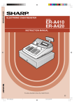
Once this converter is installed, it can convert :
• the symbols and comments, contained in an .SCY file,
• the Ladder language rungs of a PL7-2 program module (MAST, FAST, PRL or POS),
with the symbols, constants and preset values referenced in the program,
• the Grafcet chart and Ladder rungs (steps and transitions) for the CHART program
module, with the symbols, constants and preset values referenced in the program.
Conversion is automatic, with the exception of some PL7-2 objects which have no PL7
equivalent or Grafcet editor constraints (CHART module). On completion of conversion,
the user has the following files at his disposal :
• a program source file, the result of the conversion, .LD extension (conversion of a
Ladder language module) or .GR7 (conversion of a Grafcet module). This file can be
imported under PL7,
• a report file, .RPT extension, which contains the context of the conversion, the
correspondence between the objects, faults encountered during conversion and
objects to be configured. This file can be displayed or printed from the converter,
• a correspondence file, .C72 extension, which provides the correspondence between
objects contained in the old application and the objects which have been converted
(automatically or manually). This file is not generated automatically, but on the
initiative of the user (Save command in the object reassignment screen).
Ladder PL7 source
(*.LD file)
PL7-2 binary application
(hardware and software
configuration, constants,
Ladder language and
Grafcet) (*.BIN file)
and/or
symbols table
(*.SCY file)
Grafcet PL7 source
(*.GR7 file)
PL7-2
APPLICATION
CONVERTER
conversion report
(*.RPT file)
PL7-2 / PL7
object correspondence
(*.C72 file)
___________________________________________________________________________
3
Presentation of the converter
Warning
Since some objects do not have an automatic correspondence in PL7 (I/O, text
blocks, fast counters, etc) a program may not operate correctly following the
conversion. The following manual operations must therefore be performed in order
to complete the conversion :
• modify the PL7 configuration, following the instructions contained in the conversion
report,
• import the source (*.LD or *.GR7), following the instructions contained in the
conversion report,
• complete the Ladder rungs or the incomplete Grafcet charts.
1.2
Preliminary transfer of the application binary file and the
symbols table
This operation may be necessary if the binary file to be converted is not present on the
hard disk (or on floppy disk) or if the symbols are contained in an *.SYM file :
• when the *.BIN file is in the PLC memory or in a program cartridge, it must be
transferred to hard disk before it is converted. To do this, the PL7-2 under DOS or
PL7-2 under OS/2 software is required,
• when the symbols are contained in a *.SYM file, the file must previously be converted
to *.SCY. To do this, PL7-2 under DOS or PL7-2 under OS/2 is also required.
___________________________________________________________________________
4
Presentation of the converter
1.3
Procedure for converting a PL7-2 application to PL7
The conversion tool for PL7-2 applications is called from a PL7 station, which can be
accessed using one of the following commands :
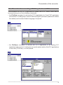
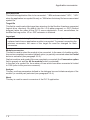
• the File/New command, to retrieve the PL7-2 application to a "new" PL7 application
and convert it. A dialog box is used to select the type of processor (and thus to define
the station) and to select Grafcet language if required :
• the File/Open command, to retrieve the PL7-2 application to an existing PL7
application and convert it. A dialog box is used to select which of the PL7 applications
on the disk (.STX files), is to be opened :
___________________________________________________________________________
5
Presentation of the converter
Then perform the following procedure to convert the application :
Access the PL7-2 application
converter.
File / Convert / PL72 application command
(see section 2.1)
(see section 2.2)
Choose the elements to be
converted (application, module,
rungs).
If necessary :
• modify the PL7 configuration, as
indicated on the screen,
• reassign the objects.
(see section 2.3-4)
(see section 2.4)
Initiate the conversion, which
generates the .LD, .GR7, .RPT and
C72 files.
Modify the PL7 configuration,
following the instructions in the
conversion report.
Import the .LD or .GR7 file under
the program editor, following the
instructions in the conversion
report.
Update the incomplete Ladder
rungs or Grafcet charts.
(see section 2.5)
(see section 2.6)
(see section 2.6)
___________________________________________________________________________
6
ApplicationSection
conversion2
2 Application conversion
2.1
Accessing the converter
To access the conversion tools, a PL7 application must first be opened (File/New or File/
Open command). The PL7-2 application converter can then be accessed via the File
menu, by activating the Convert/PL72 application command.
2.2
Choosing the elements to be converted
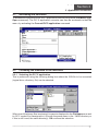
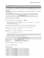
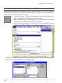
2.2-1 Selecting the PL7-2 application
This is performed using the following dialog box where the .BIN file to be converted
(logical drive, directory, file) can be selected.
When one of the binary files is selected, its name is displayed in the File Name zone and
its .SCY symbol file is assigned to it (file with the same name in the ..\MOD directory or
if this is not found, the same directory). OK confirms the selection.
___________________________________________________________________________
7
Application conversion
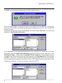
If however, there is no symbol file with the same name as the PL7-2 binary file, the user
is asked if he would like to associate another symbol file to it.
If the user selects No, no symbol file will be associated with the .BIN file. Conversely,
if the user selects Yes, the following dialog box is displayed so that an .SCY symbol file
may be chosen.
This same dialog box will also be displayed if the user selects SCY File in the following
dialog box (Application Selection).
If the application to be converted comprises only a symbol file, select this as shown
previously, using the Application Selection dialog box (logical drive, directory). In the
List Files of Type ... field, select the Symbol Files (*.scy) item, which displays the list
of symbol files. Select a file which will then appear in the File Name field, then confirm
with OK. In this case, only those objects with a direct equivalent in PL7 are converted.
The converter generates the source file (.LD or .GR7) which contains the result of the
conversion, however, it does not create a report file (.RPT).
___________________________________________________________________________
8
Application conversion
Note
If an application symbol file is greater than 1000 lines, all lines in excess of 1000 will
be ignored during conversion. This is indicated by a dialog box which enables the
symbol analysis to be continued or quit.
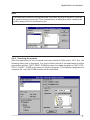
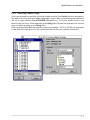
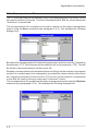
2.2-2 Selecting the module
After the application to be converted has been selected (.BIN and/or .SCY file), the
following dialog box is displayed. It is used to define which of the application modules
are to be converted : FAST, MAST, SYMB the case of a Ladder program or FAST, PRL,
POST, CHART, SYMB in the case of a Grafcet program. If the selected application is
a symbol file, only the SYMB module can be accessed.
___________________________________________________________________________
9
Application conversion
Activated files
This field lists application files to be converted : *.BIN and associated *.SCY, *.SCY
when the application is a symbol file only or *.BIN when the binary file has no associated
symbol file.
Target file
This field is used to select the target tree-structure for the file after it has been converted
(logical drive, directory). By default, this file .LD (Ladder program) or .GR7 (Grafcet
program) takes the name of the PL7-2 source application. It can, nevertheless, be
modified as long as the .LD or .GR7 extension is retained.
Important
This file is created during the initial conversion but is consequently overwritten and
replaced each time an application module is converted. To prevent overwriting the
previous conversion, the name of the target file must be changed for each
conversion.
Module conversion
This field is used to select the module to be converted. In the case of a Ladder module,
this can be completely converted (default option) or partially converted when the Partial
button is activated (see paragraph 2.2-3).
Grafcet modules and symbol files are completely converted (the Conversion option
field is grayed out and the All the module button is activated).
In the case of a symbol file, the number of lines which have been converted is limited
to 1000 (refer to the previous comment).
Analyze
This key confirms parameters defined in the dialogue box and initiates analysis of the
module (or module part) selected (see paragraph 2.2-4).
Abort
This key is used to cancel conversion of the PL7-2 application.
___________________________________________________________________________
1 0
Application conversion
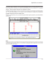
2.2-3 Selecting Ladder rungs
If the user chooses to partially convert a Ladder module (the Partial button is activated),
the label of the first and last Ladder language rungs to be converted must be defined in
the list of rungs offered (List of RUNGS dialogue box). To do this, double click on the
label for the first rung. It then appears in the Rung field. Repeat the operation for the last
rung. Its label appears in the Rung field.
After confirming with OK, the selected rungs (for example, %L25 to %L95) are displayed
in the selection dialog box for the module which will then be partially converted.
___________________________________________________________________________
1 1
Application conversion
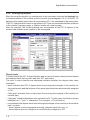
2.2-4 Reassigning objects
After choosing the module (or module part) to be converted, activate the Analyze key
to initiate analysis of the module by the converter (see paragraph 2.2-3). All the PL7-2
objects in the module which have an equivalent in PL7, are translated to the new syntax.
The PL7-2 objects which have no equivalent in PL7 are not translated and their positions
in the Ladder language rungs or Grafcet charts will remain empty.
After the analysis, the following dialog box summarizes all the PL7-2 objects in the
module and enables some objects to be reassigned.
Object family
This field lists all the PL7-2 object families and is used to choose a family whose objects
are displayed with their symbol and their PL7 equivalent.
The color in which families are displayed indicates whether the objects have been
translated :
• black indicates that PL7-2 objects were found during the analysis of the module (or
the module part) and that objects of the same type have been automatically assigned
in PL7,
• "dark gray" indicates that no object was found during the analysis of the module (or
module part),
• "light gray" indicates that there is no equivalent in PL7 (in this case, the family is shown
between two "<" and ">" characters. For example, <<Text block>>),
• red indicates that objects were found during the analysis of the module (or the module
part), but that :
- these objects must be assigned manually (discrete input bits, etc), or
- these objects are not configured or insufficiently configured in PL7.
___________________________________________________________________________
1 2
Application conversion
Used
For the selected family this field displays :
• in the Source zone : the first and last objects found during the analysis of the module
(or module part). The total number of objects founds appears in brackets. For
example, from B0 to B208 (64),
• in the Target zone : the PL7 objects equivalent to the objects found during the analysis
of the module (or module part). The total number of objects found appears in brackets.
For example, from %M0 to %M208 (64). During automatic conversion, the address of
the objects is not modified. For example, B56 becomes %M56.
Configured
This field indicates the number of objects configured under PL7, for the selected family.
For families whose objects must be assigned manually (for example discrete output
bits), the message "NOT ASSIGNED" is displayed.
For families whose objects have not been fully configured in PL7, the message
"INSUFFICIENT" is displayed. In this case, it is advisable to initiate the configuration
editor, then access the configuration of PL7 objects, so that it can be modified for objects
which have not been fully configured (their family name is displayed in red in the Object
family field and INSUFFICIENT appears in the Configured field).
Reassign
One or more objects of the selected family can be reassigned in this field. As the syntax
of the objects is given in the entry zones (for example, Bi), only the address of the object
needs to be entered (for example, B6) :
• from : first PL7-2 object to be reassigned,
• to : last PL7-2 object to be reassigned,
• into : first PL7 object of the target range.
Notes
It is also possible to define the first and last objects to be reassigned, by clicking on objects in the
PL7_2 column of the Proposals field.
To reassign a single object, it is advisable to enter the destination object directly in the PL7 column
of the Proposals field.
Proposals
This field gives the list of conversions performed for the selected family. For each object
converted it gives the symbol of the object, the name of the PL7-2 object and its
equivalent in PL7. The PL7 object can be modified by positioning the cursor on the object
on the object concerned (right column) and then by changing its address via the
keyboard.
Parameters
This field is used to create (Save) or load (Retrieve) a correspondence file *.C72 (see
section 2.6).
Select. Module
This key displays the selection dialogue box for a module (see paragraph 2.2-2).
Quit
This key is used to quit the conversion function for PL7-2 applications.
___________________________________________________________________________
1 3
Application conversion
Convert
This key starts the translation of the PL7-2 module (or module part) to source PL7 (.LD
or .GR7 file), which generates the report file .RPT (see section 2.4).
In the case of a Grafcet module, the converter translates the chart first then the ladder
language rungs associated with the chart (steps and transitions).
Once a Grafcet page has been converted, all the Grafcet pages of the module are
converted, even if they are empty. The Grafcet should therefore be imported into a "new"
CHART module.
The Grafcet conversion in itself does not require any reconfiguration. However, some
graphic combinations are no longer authorized under the PL7 Grafcet editor. These non
converted paths are indicated in the report file .RPT and must be modified either under
PL7-2 (recommended), or when the source file is imported under the PL7 Grafcet editor.
Warning
If a single programmed element (step or transition) is deleted or moved when
imported, it will no longer be possible to continue : importing the source corresponding
to the deleted step or transition is no longer possible since the line / column labels
do not correspond to the elements on the screen. The entire import is therefore
cancelled.
The non-converted graphic combinations are described in section 3.2.
The conversion of ladder language rungs is identical whether the rung belongs to a
Ladder module (or module part) or whether it is associated with a Grafcet module (step
or transition programmed in Ladder).
If there are no ladder language rungs programmed in a Grafcet module, the conversion
tables are empty after analysis and the user has the possibility to convert the Grafcet.
In this case, the conversion report indicates that the translated module does not contain
any ladder language rungs.
___________________________________________________________________________
1 4
Application conversion
2.3
Result of the conversion
After converting a PL7-2 application, the user has at his disposal a Ladder or Grafcet
source file and also a report file (*.RPT) which is automatically displayed and which can
be printed.
This text file enables the converted application to be retrieved under PL7. To do this, it
has two parts :
• RECOMMENDATIONS which guide the user through the remaining operations :
• CONVERSION REPORT which contains the result of the conversion. In the case of
a Grafcet module this comprises the chart conversion report, then the associated
Ladder conversion report (steps and transitions).
___________________________________________________________________________
1 5
Application conversion
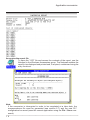
Accessing the report file
To open the *.RPT file and access the contents of the report, use the
Notepad in the Windows Accessories group. The Notepad enables the
report to be displayed and printed and, if required, customized using the
entry functions.
Note
If the conversion is interrupted in order to be completed at a later date, the
correspondence file must be generated (see section 2.7) and the new PL7
configuration be saved (save the current application using the File / Save command).
___________________________________________________________________________
1 6
Application conversion
2.4
Reconfiguring PL7 objects
If families of PL7 objects were not configured when the objects were reassigned (see
paragraph 2.2-4), the list of these objects appears at the beginning of the conversion
report (RECOMMENDATIONS part). The following must be completed :
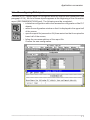
• initiate the configuration editor then access the configuration of the PL7
objects,
• resize the configuration window so that it is displayed in the upper half
of the screen,
• open the report file (see section 2.4) then resize it so that it occupies the
lower half of the screen,
• follow the recommendations of the report file.
Confirm the new configuration.
___________________________________________________________________________
1 7
Application conversion
2.5
Importing the Ladder or Grafcet source file
If the conversion has been interrupted after the creation of the .LD or .GR7 source file,
reestablish the conversion context by opening the .STX file which has been saved. To
import the Ladder or Grafcet source file :
• initiate the Ladder or Grafcet station editor then resize the window so
that it is displayed in the upper half of the screen,
• open the report file if it is not on the screen (see section 2.4) then resize
it so that it occupies the lower half of the screen,
• follow the recommendations in the report file ; that is, initiate the import
of the .LD or .GR7 file (File menu, Import command).
• define the tree-structure of the source file (.LD or .GR7) to be imported (logical drive,
directory, file name) then start its import with OK.
___________________________________________________________________________
1 8
Application conversion
During the import operation, all the Ladder language rungs or Grafcet charts which have
been converted correctly are inserted automatically into the selected PL7 program
module. These program elements are displayed in black.
Ladder language rungs or charts converted incorrectly are incomplete and displayed in
red. The recommendations in the report must be followed to update the incomplete
program elements and thus validate them.
Graphic combinations not converted during the chart import operation, are described in
section 3.2
Note :
Program elements are imported as "discrete" logic and the import stops when it meets an incorrectly
converted program element. The error is indicated in a dialog box which enables the user to either
correct or continue the import.
___________________________________________________________________________
1 9
Application conversion
2.6
Correspondence file
The .C72 correspondence file enables a copy of the reassignments to be saved, so that
they can be retrieved if need be. This file is associated with a .BIN file, whose name and
"checksum" is memorized.
The correspondence file is created on the user's initiative on the object reassignment
screen using the Save command (see paragraph 2.2-4). This displays the following
dialogue box :
By default the correspondence file takes the same name as the source file, followed by
the extension .C72. The file name can be modified, but not its extension (.C72). This will
be saved in the same directory as the source file.
Reading a correspondence file enables objects resulting from the analysis of a program
module (or a module part) to be reassigned, according the values saved in this source
file. A check is performed to ensure that a .C72 file can only be loaded if it corresponds
to the .BIN file used for the save (name and "checksum" check).
The correspondence file is read from the object reassignment screen using the Retrieve
command (see paragraph 2.2-4). This displays the following dialogue box :
___________________________________________________________________________
2 0
Appendix3
Section
3 Appendix
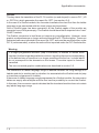
3.1
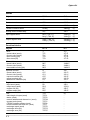
Correspondences between PL7-2 and PL7 objects
PL7-2 objects with a direct equivalent in PL7 are automatically translated by the
converter. Objects with no direct equivalent can be reassigned by the user in the "Object
reassignment" screen or replaced under the program editor when importing. These
objects are indicated in the tables via the reference numbers :
(1) these objects do not have a direct equivalent. They must be reassigned by the user
in the "Object reassignment" screen.
(2) these objects do not have a direct equivalent. They are translated as "blanks" by the
converter.
(3) system objects with a direct equivalent in PL7 are automatically reassigned by the
converter. The remaining system objects must be reassigned by the user in the
"Object reassignment" screen.
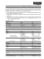
Immediate values
Objects
PL7-2
PL7
Base10 integer
1234
1234
Base 2 integer
L'10011110'
2#10011110
Base 16 integer
H'ABCD'
#ABCD
Character string
M'aAbBcB'
'aAbBcC'
Objects
PL7-2
PL7
Input bit
RUN / STOP input
Event-triggered input
Ix,i (TSX 17)
Iy,i (TSX 27)
Ixy,i (TSX 47)
I0,0 (TSX 17)
I0,24 and I0,25 (TSX 17)
%Ix(y).i
(1)
%Ixy.i
(1)
%Ixy.i
(1)
%I1.8 (TSX 37) (1)
%I1.0 to %I1.3 (TSX 37)(1)
SECU output
Ox,i (TSX 17)
Oy,i (TSX 27)
Oxy,i (TSX 47)
O0,0 (TSX 17)
%Qx(y).i
%Qx(y).i
%Qx(y).i
%Q2.0 (TSX 37)
Bits
Output bit
(1)
(1)
(1)
(1)
Internal bit
Bi
%Mi
System bit
SYi
%Si
Step bit
Xi
%Xi
Fault bit
Sx,i (TSX 17)
I/Oxy,S (TSX 27/47)
%Ix(y).MOD.ERR (module)
%Ix(y).i.ERR (channel) (2)
(3)
Bit j of internal word i
Wi,j
%MWi:Xj
Bit j of system word i
SWi,j
%SWi:Xj
(3)
Bit k of common word j
of station i
COMi,j,k
%NWi.j:Xk
(1)
Bit j of input register word i
IWx,i,j
%IWx(y).i:Xj
(1)
Bit
j of output register word i
OWx,i,j
%QWx(y).i:Xj
(1)
___________________________________________________________________________
2 1
Appendix
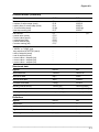
Words
Objects
PL7-2
PL7
Internal word
Wi
%MWi
Constant word
CWi
%KWi
System word
SWi
%SWi
(3)
TELWAY common word
COMi,j
%NW{i}j
(1)
Activity time of Grafcet step
Xi,V
%Xi.T
Input register word
IWx,i (TSX 17)
IWxy,i (TSX 47)
%IWx(y).i
%IWx(y).i
Output register word
OWx,i (TSX 17)
OWxy,i (TSX 47)
%QWx(y).i (1)
%QWx(y).i (1)
(1)
(1)
Function blocks
Objects
PL7-2
PL7
Timer
• preset value (word)
• current value (word)
• timer running (bit)
• timer done (bit)
Ti
Ti,P
Ti,V
Ti,R
Ti,D
%Ti
%Ti.P
%Ti.V
%Ti.R
%Ti.D
Monostable
• preset value (word)
• current value (word)
• monostable running (bit)
Mi
Mi,P
Mi,V
Mi,R
%MNi
%MNi.P
%MNi.V
%MNi.R
Up/down counter
• preset value (word)
• current value (word)
• upcount overflow (bit)
• preset reached (bit)
• downcount underflow (bit)
Ci
Ci,P
Ci,V
Ci,E
Ci,D
Ci,F
%Ci
%Ci.P
%Ci.V
%Ci.E
%Ci.D
%Ci.F
Register
• input word (word)
• output word (word)
• register full (bit)
• register empty (bit)
Ri
Ri,I
Ri,O
Ri,F
Ri,E
%Ri
%Ri.I
%Ri.O
%Ri.F
%Ri.E
Text
• table length in bytes (word)
• status (word)
• module address and channel no. (word)
• request code (word)
• TELWAY station address (word)
• communication text block no. (word)
• exchange report (word)
• exchange done (bit)
• exchange error (bit)
TXTi
TXTi,L
TXTi,S
TXTi,M
TXTi,C
TXTi,A
TXTi,T
TXTi,R
TXTi,D
TXTi,E
(2)
-
___________________________________________________________________________
2 2
Appendix
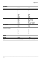
Function blocks (continued)
Objects
PL7-2
PL7
Drum controller
• number of active steps (word)
• activity time of current step (word)
• 16 control bits (word)
• last step running (bit)
Di
Di,S
Di,V
Di,Wj
Di,F
%DRi
%DRi.S
%DRi.V
%DRi.Wj
%DRi.F
Fast counter
• preset value (word)
• current value (word)
• external reset (bit)
• preset reached (bit)
• counter running (bit)
FC
FC,P
FC,V
FC,E
FC,D
FC,F
-
(2)
Real-time clock
• "WEEK" or "YEAR" type
day selection MTWTFSS (word)
• start of setpoint (word)
• end of setpoint (word)
• current value < setpoint (bit)
• current value = setpoint (bit)
• current value > setpoint (bit)
H
-
(2)
-
-
Objects
PL7-2
PL7
Word extract bit
<word>,i
<word>:Xi
Internal bit table
Bi[L]
%Mi:L
Internal word table
Wi[L]
%MWi:L
Constant word table
CWi[L]
%KWi:L
Indexing internal words
<word>(Wi)
<word>[%MWi]
Indexed word extract bit
<word>(Wi),j
<word>[%MWi]:Xj
Indexing table by word
<object>(Wi)[L]
<object>[%MWi]:L
Structured data
Delimiters
Objects
PL7-2
PL7
Assignment
->
:=
Left bracket for indexing
(
[
Right bracket for indexing
)
]
Table length
[length]
:length
___________________________________________________________________________
2 3
Appendix
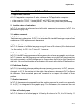
Operators
Objets
PL7-2
PL7
+
*
/
AND
OR
XOR
MOD
+
*
/
AND
OR
XOR
REM
BIN
BCD
CPL
BTA
ATB
INT_TO_BCD
BCD_TO_INT
NOT
INT_TO_STRING
STRING_TO_INT
SLC
SRC
ROL
ROR
>
<
>=
<=
=
<>
>
<
>=
<=
=
<>
Binary operator
Unary operator
Shift operator
Comparison operator
Labels
Objects
PL7-2
PL7
Label
Li i = 0 to 999
%Li i = 0 to 999
___________________________________________________________________________
2 4
Appendix
3.2
1
Differences between PL7-2 and PL7
Application structure
A PL7-2 application comprises 2 tasks, whereas a PL7 application comprises :
• in the case of a TSX 37, 2 tasks (MAST and FAST) plus event processing,
• in the case of a TSX 57, 3 tasks (MAST, FAST and AUX) plus event processing.
2
Ladder order of evaluation
In PL7-2, evaluation is performed from left to right, sequence by sequence. In PL7, it is
performed rung by rung.
3
Ladder comment
In PL7-2, the comment is integrated in a Ladder language rung and has a maximum of
15 alphanumeric characters. In PL7, it is integrated in a Ladder language rung and has
a maximum of 255 alphanumeric characters.
4
Size of Ladder rungs
In PL7-2, the size of a Ladder language rung is 4 lines of 10 columns (9 for the test and
1 for the action). In PL7, it is 7 lines of 11 columns.
5
Grafcet convergences and divergences
In PL7-2, the AND convergences and divergences do not have any graphic restrictions.
In PL7, however, an AND convergence is always drawn from right to left (step/transition
link) and conversely, an AND divergence is always drawn from left to right (transition/
step link). Non-converted paths are indicated in the report with details of their position.
6
Pathline in Grafcet
In PL7-2, it is possible to draw a pathline above an incoming connector. In PL7, however,
this is not allowed. This is because the annotation of the connector numbering has
changed : in PL7-2, the number is to the right of the reference, whereas in PL7 it is above
the reference. Non-converted paths are indicated in the report with details of their
position.
7
Grafcet comment
In PL7-2, the comment is separate from the graphic page and is saved in an appendix
file. In PL7, it is integrated in the graphic page. For this reason, the comments are not
converted.
8
Size of Grafcet pages
In PL7-2, the size of a Grafcet page is 14 lines by 8 columns. In PL7, it is 14 lines by 11
columns.
___________________________________________________________________________
2 5
Appendix
3.3
1
Special cases
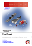
Problems associated with evaluation of a Ladder rung
The following examples concern PL7-2 Ladder rungs which are converted to PL7, with
an identical graphic form, but which are evaluated differently (different result on
execution). These Ladder rungs contain an object which is simultaneously evaluated
and updated; it is updated using a coil or function block.
• Updating by a coil
- with PL7-2, the contact B2 (%M2) was evaluated before the coil B2 (%M2),
- with PL7, the coil %M2 is updated before contact %M2 is evaluated.
%M0
%M2
%M2
%M0
%M2
%M4
%M2
%M4
• Updating by a function block
- with PL7-2, timer T1 (%T1) was called before contact T1,R (%T1.R) was evaluated,
- with PL7, contact %T1.R is evaluated before timer %T1 is called.
%T1.R
%M0
E
%T1
%M2
%T1.R
%M0
D
%M1
E
%T1
%M2
%M4
D
%M1
C
R
C
R
Note
These different evaluations are not detected by the converter.
___________________________________________________________________________
2 6
Appendix
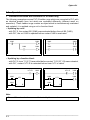
2
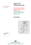
Ladder rungs not permitted in PL7
Certain Ladder rungs (very rare) entered
in PL7-2, are not accepted in the
compilation by PL7. For example, nested
rungs which can be entered under PL7-2,
are not permitted in PL7 as they are
inconsistent with the new evaluation order.
These Ladder rungs prohibited in PL7, are
detected on import of the conversion result.
The user must therefore delete or modify
them in order to continue the import.
3
%T1.R
STOP
E
C
%T1
%M0
D
R
%T1.D
%M1
Saved bits
I/O and internal bits, not saved in PL7-2, are systematically saved in PL7. This may result
in different operations on a warm restart.
4
Pre-configuration of TSX 47 PLC I/O
I/O bits present in a PL7-2 TSX 47 program cannot be differentiated by the converter
(Ixy,i input bits or Oxy,i output bits) unless they are configured in PL7-2. This only applies
to PL7-2 application programs for TSX 47 or TSX 47-20.
5
Remote I/O
PL7 remote I/O objects cannot be reassigned as PL7-2 I/O objects.
6
Constant words
The values of CWi constant words encountered during a conversion are translated.
The presence of an indexed CWi in a converted program (only possible for constant
words CW0 and CW127) results in the translation of all CW0 to CW127 constant words.
In PL7-2, in order to recuperate the value of constant words which cannot be
accessed by program (≥ CW128), transfer the value to an internal word table (for
example, CW200[40] -> MW10[40]). The presence of this type of instruction in the
converted program results in the translation of tranferred CWi and their values. All
transferred CWi therefore appear in the "Constant word" family.
___________________________________________________________________________
2 7
Appendix
7 Bit and word tables
When a bit table (for example, I1,8[16] in PL7-2 notation or %I1.8:16 in PL7 notation) is
present in the program to be translated, a "non-configured object" message may appear
during import of the conversion report. The Ladder rungs concerned must therefore be
rectified before continuing with the import or the PL7 configuration modified, if this is
possible.
When a word table (for example, W512[60] in PL7-2 notation or %MW512:60 in PL7
notation) is present in the program to be translated, a "non-configured object" message
may appear during import of the conversion report. The Ladder rungs concerned must
therefore be rectified or the PL7 software configuration modified (number of %MWi),
according to the maximum size of the imported word table.
Note
The converter does not accept bit table or word table objects in its object family, only
bit or word objects referenced in the program (for example %I1.8 or %MW512 in the
examples above). This note does not apply to constant words (see 6 - Constant
words)
8 ASCII / Binary and Binary /ASCII conversions
The conversion of PL7-2 operators : BTA (Binary To ASCII) and ATB (ASCII To Binary)
is special because the corresponding PL7 operators (INT_TO_STRING and
STRING_TO_INT) do not work on the same type of objects. For example,
PL7-2
PL7
BTA CW10 -> W50
%MB100:6 := INT_TO_STRING(%KW10)
ATB W4 -> W50
%MW50 := STRING_TO_INT(%KB8:6)
BTA outputs 3 words (W50, W51 and W52 in the example above) whereas
INT_TO_STRING supplies a string of 6 characters.
9 MAST and FAST task
Differences in structure and operating modes for the tasks of a PL7-2 application and
those of a PL7 application (presence of event processing, etc) may result in a different
organization of the programs.
___________________________________________________________________________
2 8
Index
Index
PL7-2 application converter
A
Activated files
Activity time of Grafcet step
All the module
Analyze
Application selection
Application structure
ASCII/Binary conversion
F
10
22
10
10, 12
8
25
28
B
*.BIN file
Binary/ASCII conversion
Bits
Bit table
Black
4
28
21
28
12
C
CHART
Chart conversion report
Checksum
Comment in Grafcet
Comment in Ladder
Configuration editor
Configured
Constant words
Convergences and divergences
Conversion option
Convert
Correspondence file
9
15
20
25
25
17
13
27
25
10
14
3, 20
D
Delimiters
Drum controller
23
23
E
Event-triggered input
21
FAST
Fast counter
FAST mask
File Name
File name
File/Convert/PL7-2 application
File/Convert/PL72 application
File/Import
File/New
File/Open
File/Save
Function blocks
9
23
28
7
8
6
7
18
5, 7
5, 7
16
22, 23
G
Grafcet
Grafcet source file
Gray
5
18
12
I
Immediate values
INSUFFICIENT
21
13
L
Labels
Ladder conversion report
Ladder evaluation
25,
Ladder language rungs not permitted in
PL7
Ladder source file
List Files of Type
List of RUNGS
24
15
26
27
18
8
11
M
MAST
MAST task
Module conversion
..\MOD Directory
Modules in Grafcet
Modules in Ladder
Monostable
9
28
10
7
9
9
22
___________________________________________________________________________
29
B
Index
N
NOT ASSIGNED
Notepad
T
13
16
O
Object family
Operator
12, 13
24
13
10, 11
25
9
27
9
3
13
13
10
22
22
U
Up/down counter
Used
P
Parameters
Partial
Pathline
POST
Pre-configuration of I/O
PRL
Program source file
Proposals
Target
Target file
Text
Timer
22
13
W
Words
Word table
22
28
R
Reassign
RECOMMENDATIONS
Red
Register
Remote I/O
Report file
Retrieve
RUN/STOP input
Rung
13
15
12
22
27
3, 14, 16
13, 20
21
11
S
Save
Saved bits
.SCY file
SECU output
Select. Module
Size of Grafcet pages
Size of rungs
Source
Structured data
*.SYM file
SYMB
Symbol Files (*.scy)
13, 20
27
3, 8
21
13
25
25
13
23
4
9
8
___________________________________________________________________________
30
02
*W913293990301A*
W913293990301A 02
Schneider Electric Industries SAS
Headquarters
89, bd Franklin Roosevelt
F - 92506 Rueil Malmaison Cedex
Owing to changes in standards and equipment,
the characteristics given in the text and images
in this document are not binding us
until they have been confirmed with us.
http://www.schneider-electric.com
Printed in
March 2005