1
TI Designs
Smart Electrical Meter Development Platform (SMB 3.0)
Design Guide
TI Designs
TI Designs provides the foundation that you need
including methodology, testing, and design files to
quickly evaluate and customize and system. TI
Designs helps you accelerate your time to market.
Design Resources
www.ti.com/product/lm3s1b21
Application Processor
www.ti.com/product/trf7970a
www.ti.com/product/cc3000
www.ti.com/tool/cc2530emk
www.ti.com/smartgrid
RFID
CC3000
CC2530
Smart Grid
ASK Our E2E Experts
WebBench Calculator Tools
Kit Contents and Requirements
• Smart Meter Board + AC Power Coord
• SimpleLink™ CC3000 Wi-Fi Evaluation
Module
• TRF7970A RFID Target Board
• PLC Daughter Boards and Module
• 2 CC2530 RF Transceiver Daughter Boards
• IHD430, Low-Cost Segment Based In-Home
Display
• 1-Phase Metrology Module
(MSP430AFE253)
• Application Microcontroller Module
(Stellaris® LM3S1B21)
• Data Concentrator Board (Not Included)
• Wi-Fi GUI SW is Provided in the Zip File
Accompanying this Document.
Design Features
• Modular and Scalable Smart Meter
Development Platform Helps Developers
Design Low-End to Advanced Smart Meters
for AMR and AMI Systems.
• Open Platform Lets Developers Customize
their Designs for Further Development or
Differentiation.
• ARM® Cortex™-M Application
Microcontrollers
• Wi-Fi Capability Allows Smart Meters to
Connect to an IP Network so Customers can
Communicate with the Smart Meter through
a Wi-Fi-Connected Computer, Smartphone
or Tablet, without the Additional Cost and
Complexity of a Gateway.
• Support for Low-Power RF (Sub-1GHz and
2.4-GHz ZigBee) Implementations Connects
a Meter to a Home Area Network (HAN) for
Short-Range Communication.
• Easy Software Integration with Support for
TI Smart Grid Software Libraries, including
ZigBee SEP 1.x and 2.0, WMBUS,
802.15.4g, One-Phase/Two-phase
metrology, THD, DLMS, Pre-Payment,
MIFARE™ and Encryption.
• Supports PLC for PRIME/G1/G3/P1901.2 for
Low-Frequency Narrowband
Communication.
• NFC Capabilities Introduce Options for PrePayment of Energy.
An IMPORTANT NOTICE at the end of this TI reference design addresses authorized use, intellectual property matters and other
important disclaimers and information.
All trademarks are the property of their respective owners.
TIDU213 – February 2014
Submit Documentation Feedback
Smart Electrical Meter Development Platform (SMB 3.0) Design Guide
Copyright © 2014, Texas Instruments Incorporated
1
Overview
1
www.ti.com
Overview
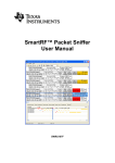
The Smart Meter Board (SMB) from Texas Instruments is a comprehensive modular and scalable tool
to demonstrate the capabilities of a Smart Meter along with the smart grid’s most prolific
communications protocols. The SMB is a unique modular and scalable environment that lets
developers include multiple wired and wireless communication protocols including power line
communication ( PLC), near field communication (NFC), Wi-Fi, sub-1GHz and 2.4GHz ZigBee ® Smart
Energy Profile (SEP) on e-metering applications. The SMB performs energy or electricity metering and
has the capability of transferring key meter data via wired and wireless sensors to showcase Automatic
Meter Reading (AMR) and Automatic Metering Infrastructure (AMI) systems.
2
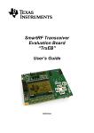
Block Diagram
SMB3.0 Outline
WiFi
ZigBee/Sub 1GHz
LCD
Connector X1
UART1
SPI0
Connector X0
Module B
Module A
SPI0
UART1
Metrology
RFID
Connector Y0
Default: AFE430
Single Phase, Two
Phase, Three
Phase
UART0
Connector X2
UART0
SPI1
Application
Processor
Module D
Module C
UART2
PLC
SPI1
Connector Z0
UART2
Module E
Module F
POWER
App Processor Peripherals Available:
SPI – 2
I2C – 2
UART – 3
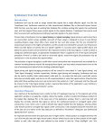
Figure 1. SMB Block Diagram
2
Smart Electrical Meter Development Platform (SMB 3.0) Design Guide
Copyright © 2014, Texas Instruments Incorporated
TIDU213 – February 2014
Submit Documentation Feedback
Overview of Block Diagram
www.ti.com
3
Overview of Block Diagram
The SMB from Texas Instruments is a comprehensive tool to demonstrate the capabilities of a Smart
meter. The Smart Meter Board (SMB) performs energy or electricity metering and has the capability of
transferring key meter data via wired and wireless sensors to form a simple Automatic Meter Reading
(AMR) system.
The SMB board supports the following Modules (Refer to Figure 1):
Application processor available peripherals are 3 UART’s, 2 SPI and 2 I2C.
Modules Supported by SMB and Communication Interface to Application Processor
Module
Supported Modules
Module A
•
•
•
•
•
•
Sub 1 GHz Transceiver
Sub 1 GHz SoC Module
ZigBee Transceiver
ZigBee SoC Module
RFID
WiFi
Module B
• Sub 1 GHz Transceiver
• Sub 1 GHz SoC Module
• ZigBee SoC
Module C
•
•
•
•
•
•
Sub 1 GHz Transceiver
Sub 1 GHz SoC Module
ZigBee Transceiver
ZigBee SoC Module
RFID
WiFi
Communication
interface to
Application
Processor
Notes
SPIO
20x2 Pin Connector X0
UART1
20x2 Pin Connector X1
ZigBee Transceiver
Module not supported
SPI1
20x2 Pin Connector X2
Module D
Metrology(1, 2, 3 Phases)
UART0
Connector Y
Module E
PLC
UART2
34 Pin Connector Z
ModuleC
Application Processor (Stellaris/Sitara...)
N/A
From Modules Supported by SMB and Communication Interface to Application Processor, it can be
inferred that
• Connector's A, B, and C support multiple daughter boards.
• Connector METROLOGY dedicated for Metrology.
• Connector PLC_CONNECTOR dedicated for PLC.
TIDU213 – February 2014
Submit Documentation Feedback
Smart Electrical Meter Development Platform (SMB 3.0) Design Guide
Copyright © 2014, Texas Instruments Incorporated
3
Overview of Block Diagram
www.ti.com
Table 1 lists all use cases that can be supported or not supported by SMB at any time.
Note: As METROLOGY and PLC_CONNECTOR are dedicated to Metrology and PLC, the assumption
that the 2 daughter boards (Metrology and PLC) are plugged into SMB can be made.
Table 1. Supported and Not Supported Daughter Boards
Use Case No
Connector A (SPI)
Connector B (UART)
Connector C (SPI)
Supported(√)
1
ZigBee SoC
Sub 1GHz SoC
WiFi
√
2
ZigBee Transceiver
Sub 1GHz SoC
WiFi
√
3
ZigBee SoC
Sub 1GHz Transceiver
WiFi
√
4
ZigBee Transceiver
Sub 1GHz Transceiver
WiFi
√
5
ZigBee SoC
Sub 1GHz SoC
RFID
√
6
ZigBee Transceiver
Sub 1GHz SoC
RFID
√
7
ZigBee SoC
Sub 1GHz Transceiver
RFID
√
8
ZigBee Transceiver
Sub 1GHz Transceiver
RFID
√
9
RFID
Sub 1GHz Transceiver
WiFi
√
10
RFID
Sub 1GHz SoC
WiFi
√
11
RFID
ZigBee SoC
WiFi
√
12
RFID
ZigBee Transceiver*
WiFi
Not Supported (X)
X
Only 5 modules can be active at the same time, so the RFID, ZigBee, WiFi, and <1 GHz can not function
simultaneously.
4
Smart Electrical Meter Development Platform (SMB 3.0) Design Guide
Copyright © 2014, Texas Instruments Incorporated
TIDU213 – February 2014
Submit Documentation Feedback
Set-Up Instructions
www.ti.com
4
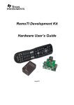
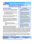
Set-Up Instructions
Figure 2. Smart Meter Board Top View
4.1
Step 1: Set Up Access Point
•
•
•
Connect the power adaptor to the access point and turn it on using the Power Button.
Verify that the Power LED is on and the Wireless LED is blinking.
The access point may take ~30 seconds to reach an operational state; then, you can find the access
point in the list of wireless networks on your computer
TIDU213 – February 2014
Submit Documentation Feedback
Smart Electrical Meter Development Platform (SMB 3.0) Design Guide
Copyright © 2014, Texas Instruments Incorporated
5
Set-Up Instructions
www.ti.com
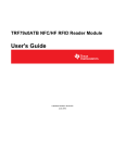
Figure 3. Access Point
The blue-colored port shown in Figure 3 is the WAN port and is not used for this setup. Only the yellowcolored ports should be used.
4.2
Step 2: Check Orientation of Daughter Boards
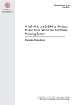
Check the orientation of the daughter boards on SMB if they are placed correctly and facing inward as
shown in Figure 4. Failure to have the right orientation will damage the daughter cards.
Figure 4. Daughter Boards Orientation
6
Smart Electrical Meter Development Platform (SMB 3.0) Design Guide
Copyright © 2014, Texas Instruments Incorporated
TIDU213 – February 2014
Submit Documentation Feedback
Set-Up Instructions
www.ti.com
4.3
Step 3: Set Jumper Settings
Set the jumper settings on SMB and application processor board as listed below to be able to demonstrate
the board successfully.
1. 3.1) RF_A_SSI Jumper: Place the Jumpers on [4 3 2 1] as shown in Figure 5.
2. 3.2) LCD_GPIO_SSI Jumper: Place the Jumpers on [4 3 2 1] as shown in Figure 5.
3. 3.3) X1_UART Jumper: Place the Jumpers on [2 1] as shown in Figure 5.
Figure 5. SMB Jumper Location
4. SMB_PWR Jumper: Place the Jumper on SMB_PWR on Application processor board as shown in
Figure 6
Figure 6. SMB-Application Processor Jumper Location
TIDU213 – February 2014
Submit Documentation Feedback
Smart Electrical Meter Development Platform (SMB 3.0) Design Guide
Copyright © 2014, Texas Instruments Incorporated
7
Set-Up Instructions
4.4
www.ti.com
Step 4: Prepare and Configure the CC3000, PowerSMB, and Your PC
Ensure the Wi-Fi daughter card is connected as mentioned in Section 4.2. Supply power to SMB by
connecting AC power cable as shown in Figure 2. Associating CC3000 Wi-Fi enabled device with an
access point and the First time Configuration process details can be obtained by referring to “Using a
Laptop” section in the link below:
http://processors.wiki.ti.com/index.php/CC3000_First_Time_Configuration
4.5
Step 5: Download Software Zip File
Download Wi-Fi GUI SW provided in the zip file. The Wi-Fi GUI was developed in Processing, download
Processing 1.5.1 to run the GUI at http://processing.org/download/
Figure 7. Wi-Fi GUI
8
Smart Electrical Meter Development Platform (SMB 3.0) Design Guide
Copyright © 2014, Texas Instruments Incorporated
TIDU213 – February 2014
Submit Documentation Feedback
Set-Up Instructions
www.ti.com
4.6
Step 6: Prepare Data Concentrator Kit
•
•
•
•
•
•
Power on AM335x data conecntrator
Wait at least one minute for the board to boot
PRIME DC will start automatically and four green LEDs next to the Ethernet connection will light up
when it has started
Run TI DC Manager to view the nodes connected
– IP Address: 192.168.0.1
– Port: 20000
Use putty to read data sent by SMB
– Putty download link: http://www.chiark.greenend.org.uk/~sgtatham/putty/download.html
• Hostname: 192.168.0.1
• Port: 22
Run "./MeterDataRead" when connected
Figure 8. Putty Configuration
TIDU213 – February 2014
Submit Documentation Feedback
Smart Electrical Meter Development Platform (SMB 3.0) Design Guide
Copyright © 2014, Texas Instruments Incorporated
9
Set-Up Instructions
4.7
www.ti.com
Step 7: Prepare ZigBee In-Home Display (IHD)
The ZigBee IHD device has its own setup mechanism and joins the ZigBee network once powered ON.
1. Provide power with 2 AAA batteries, a Flash emulation tool (FET), or an external supply. The power
source is selected by configuring jumpers on VCC and BATT headers and the power is supplied to the
on-board MSP430 by placing a jumper on PWR1 header. The power setup options are provided:
• Set jumper for battery power:
– Place jumper on BATT header.
– Place jumper on PWR1 header.
• Set jumper for Flash emulation tool power:
– Place jumper on pins [1-2] on VCC 3-pin header.
– Place jumper on PWR1 header.
• Set jumper for external power
– Place jumper on pins [2-3] on VCC 3-pin header.
– Place jumper on PWR1 header.
2. Ensure jumper is placed on RF_PWR header, which has been provided to enable and disable power to
CC2530.
With the jumper selections completed as recommended above, the IHD430 is ready to be used.
Figure 9. In-Home Display
10
Smart Electrical Meter Development Platform (SMB 3.0) Design Guide
Copyright © 2014, Texas Instruments Incorporated
TIDU213 – February 2014
Submit Documentation Feedback
Running the Demo
www.ti.com
5
Running the Demo
This section described the procedure to run the demo.
Note: Before running the demo, the set-up instructions from Section 4 must be completed:
1. Check if the access point is powered ON and verify its visible in the Wireless Network list of your
computer.
2. Check if the jumpers are set on the Smart Meter Board (Refer to Section 4.3).
3.
4. Connect AC power cable to Smart Meter Board. Press the switch on SMB to supply power to the
board. TI logo is displayed on the LCD, followed by active power in watts and status of PLC, Wi-Fi, and
RFID.
Note: Status of Wi-Fi must display connected for demo to work successfully.
5. Connect a load such as a lamp, laptop, and so on to the Load socket on SMB. The instantaneous
power consumption (meter data) of the connected load is displayed on the LCD screen.
6. Check if data concentrator is powered ON. If yes, then push the PLC_RESET button on the Smart
Meter Board to initiate data transfer to the data concentrator from SMB. Wait ~40 seconds for the
status of PLC to change from INIT to Connected. On successful connection, the meter data sent by
SMB to the data concentrator can be read using putty (refer to Section 4.6).
7. Run the Wi-Fi GUI on the PC to read the meter data transmitted over Wi-Fi.
8. Turn on the IHD to see the instantaneous power sent by SMB.
Note: The IHD must be turned ON only after the CC2530 on SMB is turned ON.
9. Place the RFID card over the RFID daughter board to showcase the RFID capabilities via the
contactless interface.
TIDU213 – February 2014
Submit Documentation Feedback
Smart Electrical Meter Development Platform (SMB 3.0) Design Guide
Copyright © 2014, Texas Instruments Incorporated
11
Hardware Description
6
www.ti.com
Hardware Description
The description of the daughter boards that can be plugged into the SMB Motherboard
6.1
Microcontroller Overview
The Application/Host processor is the 32-bit ARM® Cortex™-M3 80-MHz processor. The On-chip memory
features 256 KB Flash, 96 KB SRAM; internal ROM loaded with StellarisWare® software. Full-featured
debug solution with debug access via JTAG and Serial Wire interfaces and test pads are provided on the
application processor module. The processor is the communication processor and also the metrology
engine.
Figure 10. Application Processor Board
6.1.1
Debugging
The ICDI board is used to download and debug programs on the Application Processor board. The
ICDI_PWR jumper on the application processor board must be placed to use the debugger. The
application processor board receives 5 V from the USB bus and a DC regulator generates 3.3 V for onboard circuits. The headers are on the board, a 10 pin JTAG/SWD header J4, an 8-pin header J2. The 10pin and 8-pin headers are used to connect to the application processor board.
Figure 11. ICDI Debug Board
6.1.2
Reset
A reset switch and R-C network connects to the microcontroller’s RSTn input.
12
Smart Electrical Meter Development Platform (SMB 3.0) Design Guide
Copyright © 2014, Texas Instruments Incorporated
TIDU213 – February 2014
Submit Documentation Feedback
Hardware Description
www.ti.com
6.2
Sub-1GHz Overview
The CC1120 Evaluation Module for sub-1GHz performs the Automatic meter Reading (AMR) portion of
SMB. The evaluation Module demonstrates good techniques for CC1120 decoupling and RF layout. For
optimum RF performance, these parts should be copied correctly. The Evaluation Module is a 4-layer
design with a discrete balun and SMA antenna connector designed for a single ended 50 ohm antenna.
The RF Section has been designed for operation in the 863 to 870 MHz (EU) and 902 to 928MHz (US)
frequency bands.
Figure 12. Sub-1GHZ Radio
TIDU213 – February 2014
Submit Documentation Feedback
Smart Electrical Meter Development Platform (SMB 3.0) Design Guide
Copyright © 2014, Texas Instruments Incorporated
13
Hardware Description
6.3
www.ti.com
ZigBee Overview
The CC2520 Evaluation Module (EM) is an add-on/plug-in daughter card for SMB. The CC2520EM is
usable with a motherboard, typically SmartRF05EB and SMB. The CC2520 EM is a ZigBee/IEEE 802.5.4
RF Transceiver designed for RF Application in the 2.4GHz unlicensed ISM band and contains the RF IC
and necessary external components and matching filters for getting the most out of the radio. The
communication interface to the application processor is via UART. The module is used to perform the
Smart energy/Automatic Meter Reading (AMR) portion of SMB. The instantaneous power consumption is
sent periodically to the ZigBee module for wireless transmission. The EM can be used as reference design
for antenna and RF layout.
SmartRF Studio is a PC application developed for configuration and evaluation of many of the RF-IC
products from Texas Instruments, including the CC2520. The application is designed for use with an
applicable SmartRF evaluation board, such as the SmartRF05EB, and runs on Microsoft® Windows®.
The latest version of SmartRF Studio can be downloaded from the Texas Instruments website
(www.ti.com/smartrfstudio), where you will also find a complete user manual.
Figure 13. ZigBee Radio
14
Smart Electrical Meter Development Platform (SMB 3.0) Design Guide
Copyright © 2014, Texas Instruments Incorporated
TIDU213 – February 2014
Submit Documentation Feedback
Hardware Description
www.ti.com
6.4
Metrology Overview
The MSP430 device performs the metrology portion of SMB. The MSP430 microcontrollers for e-metering
are designed specifically for the demands of smart grid applications, TI's MSP430 microcontroller is the
perfect combination of ultra-low power and high performance analog integration. MSP430 offers devices
for one to three-phase electricity metering, as well as radio frequency wireless interfaces for automated
meter reading (AMR). The development ecosystem is optimized to support quick ramp to production thru
access to various application notes, software suites and evaluation modules. The 1-Phase, 2-Phase or 3Phase metrology daughter boards are supported on SMB. The communication interface to the application
processor is via UART.
Figure 14. Metrology Module
6.5
Power Line Communication (PLC)
Power line communications technology enhances intelligence and reliability across a broad range of smart
grid applications, including smart electrical meters. The C2000 Power Line Communication SOM enables
easy development of software-based Power Line Communication (PLC) modems. The SOM includes the
C2000 TMS320F28069 and TI's advanced PLC analog front end AFE031. The PLCSuite software
supports several communication techniques, including OFDM (PRIME/G3 and FlexOFDM) and SFSK. The
SOM includes onboard USB JTAG emulation. The communication interface to the application processor is
via the UART. A female 0.05 mil receptacle (2x17) will be used on the motherboard. Must be keyed so
that the module cannot be placed backwards
Figure 15. Power Line Communication (PLC) Module
TIDU213 – February 2014
Submit Documentation Feedback
Smart Electrical Meter Development Platform (SMB 3.0) Design Guide
Copyright © 2014, Texas Instruments Incorporated
15
Hardware Description
6.6
www.ti.com
RFID Overview
The TRF7970ATB target board incorporates the TRF7970A multi-protocol 13.56-MHz RFID/Near Field
Communications (NFC) Transceiver IC and is hardwired for SPI communications, allowing for design and
development of ultralow power high-frequency (HF) RFID systems. The TRF7970A target board supports
NFC Modes (RFID Reader and Writer, Peer to Peer and Card Emulation), ISO14443/ISO 15693 standard
based transponders. The secure RFID pre-payment feature of SMB is showcased by the contactless
transmission of data and automatic target recognition takes place through the RF signal.
Figure 16. RFID Module
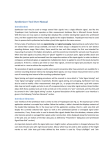
6.7
WiFi Overview
The CC3000 is a self-contained wireless network processor that simplifies the process of implementing
internet connectivity. SimpleLink™ Wi-Fi minimizes host microcontroller (MCU) software requirements,
making it the ideal solution for embedded applications using any low-cost and low-power MCU.
The CC3000 Evaluation Module (EM) board is provided to aid evaluation, reduce development time, and
minimize the amount of RF expertise required. The EM board contains the CC3000 module, and standard
RF1 and RF2 headers to connect to SMB motherboard. Additionally, this complete platform solution
includes software drivers, sample applications, API guide, and user documentation. The communication
interface to the application processor is via SPI.
The benefits of CC3000 Wi-Fi module are universal IP connectivity enabled anywhere, longer range, and
smaller board space for compact layouts.
Figure 17. Wi-Fi Module
16
Smart Electrical Meter Development Platform (SMB 3.0) Design Guide
Copyright © 2014, Texas Instruments Incorporated
TIDU213 – February 2014
Submit Documentation Feedback
IMPORTANT NOTICE FOR TI REFERENCE DESIGNS
Texas Instruments Incorporated ("TI") reference designs are solely intended to assist designers (“Buyers”) who are developing systems that
incorporate TI semiconductor products (also referred to herein as “components”). Buyer understands and agrees that Buyer remains
responsible for using its independent analysis, evaluation and judgment in designing Buyer’s systems and products.
TI reference designs have been created using standard laboratory conditions and engineering practices. TI has not conducted any
testing other than that specifically described in the published documentation for a particular reference design. TI may make
corrections, enhancements, improvements and other changes to its reference designs.
Buyers are authorized to use TI reference designs with the TI component(s) identified in each particular reference design and to modify the
reference design in the development of their end products. HOWEVER, NO OTHER LICENSE, EXPRESS OR IMPLIED, BY ESTOPPEL
OR OTHERWISE TO ANY OTHER TI INTELLECTUAL PROPERTY RIGHT, AND NO LICENSE TO ANY THIRD PARTY TECHNOLOGY
OR INTELLECTUAL PROPERTY RIGHT, IS GRANTED HEREIN, including but not limited to any patent right, copyright, mask work right,
or other intellectual property right relating to any combination, machine, or process in which TI components or services are used.
Information published by TI regarding third-party products or services does not constitute a license to use such products or services, or a
warranty or endorsement thereof. Use of such information may require a license from a third party under the patents or other intellectual
property of the third party, or a license from TI under the patents or other intellectual property of TI.
TI REFERENCE DESIGNS ARE PROVIDED "AS IS". TI MAKES NO WARRANTIES OR REPRESENTATIONS WITH REGARD TO THE
REFERENCE DESIGNS OR USE OF THE REFERENCE DESIGNS, EXPRESS, IMPLIED OR STATUTORY, INCLUDING ACCURACY OR
COMPLETENESS. TI DISCLAIMS ANY WARRANTY OF TITLE AND ANY IMPLIED WARRANTIES OF MERCHANTABILITY, FITNESS
FOR A PARTICULAR PURPOSE, QUIET ENJOYMENT, QUIET POSSESSION, AND NON-INFRINGEMENT OF ANY THIRD PARTY
INTELLECTUAL PROPERTY RIGHTS WITH REGARD TO TI REFERENCE DESIGNS OR USE THEREOF. TI SHALL NOT BE LIABLE
FOR AND SHALL NOT DEFEND OR INDEMNIFY BUYERS AGAINST ANY THIRD PARTY INFRINGEMENT CLAIM THAT RELATES TO
OR IS BASED ON A COMBINATION OF COMPONENTS PROVIDED IN A TI REFERENCE DESIGN. IN NO EVENT SHALL TI BE
LIABLE FOR ANY ACTUAL, SPECIAL, INCIDENTAL, CONSEQUENTIAL OR INDIRECT DAMAGES, HOWEVER CAUSED, ON ANY
THEORY OF LIABILITY AND WHETHER OR NOT TI HAS BEEN ADVISED OF THE POSSIBILITY OF SUCH DAMAGES, ARISING IN
ANY WAY OUT OF TI REFERENCE DESIGNS OR BUYER’S USE OF TI REFERENCE DESIGNS.
TI reserves the right to make corrections, enhancements, improvements and other changes to its semiconductor products and services per
JESD46, latest issue, and to discontinue any product or service per JESD48, latest issue. Buyers should obtain the latest relevant
information before placing orders and should verify that such information is current and complete. All semiconductor products are sold
subject to TI’s terms and conditions of sale supplied at the time of order acknowledgment.
TI warrants performance of its components to the specifications applicable at the time of sale, in accordance with the warranty in TI’s terms
and conditions of sale of semiconductor products. Testing and other quality control techniques for TI components are used to the extent TI
deems necessary to support this warranty. Except where mandated by applicable law, testing of all parameters of each component is not
necessarily performed.
TI assumes no liability for applications assistance or the design of Buyers’ products. Buyers are responsible for their products and
applications using TI components. To minimize the risks associated with Buyers’ products and applications, Buyers should provide
adequate design and operating safeguards.
Reproduction of significant portions of TI information in TI data books, data sheets or reference designs is permissible only if reproduction is
without alteration and is accompanied by all associated warranties, conditions, limitations, and notices. TI is not responsible or liable for
such altered documentation. Information of third parties may be subject to additional restrictions.
Buyer acknowledges and agrees that it is solely responsible for compliance with all legal, regulatory and safety-related requirements
concerning its products, and any use of TI components in its applications, notwithstanding any applications-related information or support
that may be provided by TI. Buyer represents and agrees that it has all the necessary expertise to create and implement safeguards that
anticipate dangerous failures, monitor failures and their consequences, lessen the likelihood of dangerous failures and take appropriate
remedial actions. Buyer will fully indemnify TI and its representatives against any damages arising out of the use of any TI components in
Buyer’s safety-critical applications.
In some cases, TI components may be promoted specifically to facilitate safety-related applications. With such components, TI’s goal is to
help enable customers to design and create their own end-product solutions that meet applicable functional safety standards and
requirements. Nonetheless, such components are subject to these terms.
No TI components are authorized for use in FDA Class III (or similar life-critical medical equipment) unless authorized officers of the parties
have executed an agreement specifically governing such use.
Only those TI components that TI has specifically designated as military grade or “enhanced plastic” are designed and intended for use in
military/aerospace applications or environments. Buyer acknowledges and agrees that any military or aerospace use of TI components that
have not been so designated is solely at Buyer's risk, and Buyer is solely responsible for compliance with all legal and regulatory
requirements in connection with such use.
TI has specifically designated certain components as meeting ISO/TS16949 requirements, mainly for automotive use. In any case of use of
non-designated products, TI will not be responsible for any failure to meet ISO/TS16949.
Mailing Address: Texas Instruments, Post Office Box 655303, Dallas, Texas 75265
Copyright © 2014, Texas Instruments Incorporated