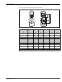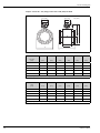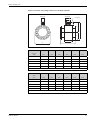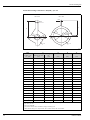
1
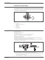
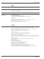
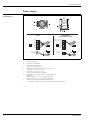
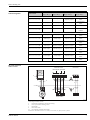
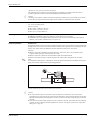
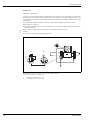
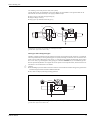
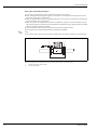
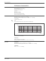
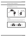
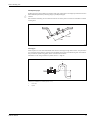
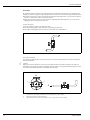
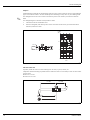
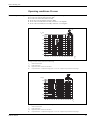
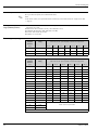
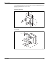
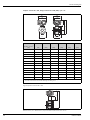
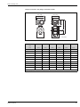
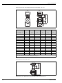
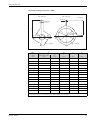
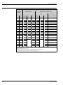
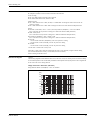
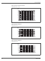
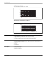
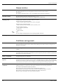
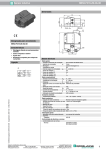
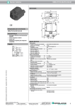
Technical Information
Proline Promag 55S
Electromagnetic Flow Measuring System
Flow rate measurement of liquids with solids content or
inhomogeneous liquids
Application
Electromagnetic flowmeter for bidirectional measurement of liquids with a minimum conductivity
of ≥ 5 μS/cm – in particular fluids with solids, and fluids
which are abrasive, inhomogeneous or tend to build-up,
for example:
• Chemical/mechanical pulps, paper pulp or wood pulp
with solids contents up to 15 Vol.-%
• Fruit mashes, fruit concentrates and final products
(salad dressings, soups with vegetable pieces)
• Slurries containing high amounts of sand or stone with
an abrasive effect, e.g. ore slurry or mortar
• Chemically inhomogeneous fluids (e.g. additives)
• Thick wastewater sludges
• Flow measurement up to 9600 m3/h
• Can be used up to +180 °C and max. 40 bar
• Fitting lengths as per DVGW/ISO
Application-specific linings and electrodes:
• Natural rubber, hard rubber, polyurethane, PTFE or
PFA linings
• Flat, bullet nose, neck, bow or brush electrodes
Approvals for hazardous area:
• ATEX, FM, CSA
TI071D/06/en/12.07
71066493
Connection to process control system:
• HART, PROFIBUS PA, FOUNDATION Fieldbus
Your benefits
Promag measuring devices offer you cost-effective flow
measurement with a high degree of accuracy for a wide
range of process conditions.
The Proline transmitter concept comprises of:
• High degree of efficiency due to the modular device
and operating concept
• Software options for: electrode cleaning, advanced
diagnostics, calculation of mass flow and solids content
The robust Promag S sensors offer:
• Universal devices, even for difficult fluids
• Excellent accuracy and repeatability
• High resistance to abrasion thanks to industryoptimized linings and measuring electrodes
• Optimum operational safety due to advanced,
permanent self-diagnosis
• Simple installation and commissioning
• Insensitive to vibration
• No pressure loss
Proline Promag 55S
Table of contents
Function and system design. . . . . . . . . . . . . . . . . . . . . 3
Measuring principle . . . . . . . . . . . . . . . . . . . . . . . . . . . . . . . . . . . 3
Measuring system . . . . . . . . . . . . . . . . . . . . . . . . . . . . . . . . . . . . . 3
Input . . . . . . . . . . . . . . . . . . . . . . . . . . . . . . . . . . . . . . 4
Measured variable . . . . . . . . . . . . . . . . . . . . . . . . . . . . . . . . . . . . 4
Measuring range . . . . . . . . . . . . . . . . . . . . . . . . . . . . . . . . . . . . . . 4
Operable flow range . . . . . . . . . . . . . . . . . . . . . . . . . . . . . . . . . . . 4
Input signal . . . . . . . . . . . . . . . . . . . . . . . . . . . . . . . . . . . . . . . . . 4
Output . . . . . . . . . . . . . . . . . . . . . . . . . . . . . . . . . . . . . 4
Output signal . . . . . . . . . . . . . . . . . . . . . . . . . . . . . . . . . . . . . . . . 4
Signal on alarm . . . . . . . . . . . . . . . . . . . . . . . . . . . . . . . . . . . . . . 5
Load . . . . . . . . . . . . . . . . . . . . . . . . . . . . . . . . . . . . . . . . . . . . . . 5
Low flow cutoff . . . . . . . . . . . . . . . . . . . . . . . . . . . . . . . . . . . . . . 5
Galvanic isolation . . . . . . . . . . . . . . . . . . . . . . . . . . . . . . . . . . . . . 5
Switching output . . . . . . . . . . . . . . . . . . . . . . . . . . . . . . . . . . . . . 5
Power supply . . . . . . . . . . . . . . . . . . . . . . . . . . . . . . . . 6
Electrical connection measuring unit . . . . . . . . . . . . . . . . . . . . . . . 6
Electrical connection terminal assignment . . . . . . . . . . . . . . . . . . . 7
Electrical connection remote version . . . . . . . . . . . . . . . . . . . . . . . 7
Electrical connections . . . . . . . . . . . . . . . . . . . . . . . . . . . . . . . . . . 8
Cable entries . . . . . . . . . . . . . . . . . . . . . . . . . . . . . . . . . . . . . . . . 8
Cable specifications (remote version) . . . . . . . . . . . . . . . . . . . . . . 8
Power consumption . . . . . . . . . . . . . . . . . . . . . . . . . . . . . . . . . . . 9
Power supply failure . . . . . . . . . . . . . . . . . . . . . . . . . . . . . . . . . . . 9
Potential equalization . . . . . . . . . . . . . . . . . . . . . . . . . . . . . . . . . . 9
Performance characteristics. . . . . . . . . . . . . . . . . . . . 13
Materials . . . . . . . . . . . . . . . . . . . . . . . . . . . . . . . . . . . . . . . . . .
Material load diagrams . . . . . . . . . . . . . . . . . . . . . . . . . . . . . . . .
Fitted electrodes . . . . . . . . . . . . . . . . . . . . . . . . . . . . . . . . . . . .
Process connections . . . . . . . . . . . . . . . . . . . . . . . . . . . . . . . . . .
Surface roughness . . . . . . . . . . . . . . . . . . . . . . . . . . . . . . . . . . .
37
37
39
39
39
Human interface . . . . . . . . . . . . . . . . . . . . . . . . . . . . 40
Display elements . . . . . . . . . . . . . . . . . . . . . . . . . . . . . . . . . . . .
Operating elements . . . . . . . . . . . . . . . . . . . . . . . . . . . . . . . . . .
Language groups . . . . . . . . . . . . . . . . . . . . . . . . . . . . . . . . . . . .
Language groups . . . . . . . . . . . . . . . . . . . . . . . . . . . . . . . . . . . .
40
40
40
40
Certificates and approvals . . . . . . . . . . . . . . . . . . . . . 40
CE mark . . . . . . . . . . . . . . . . . . . . . . . . . . . . . . . . . . . . . . . . . .
C-tick mark . . . . . . . . . . . . . . . . . . . . . . . . . . . . . . . . . . . . . . . .
Ex certification . . . . . . . . . . . . . . . . . . . . . . . . . . . . . . . . . . . . . .
Sanitary compatibility . . . . . . . . . . . . . . . . . . . . . . . . . . . . . . . . .
Pressure measuring device approval . . . . . . . . . . . . . . . . . . . . . .
FOUNDATION Fieldbus certification . . . . . . . . . . . . . . . . . . . . .
PROFIBUS PA certification . . . . . . . . . . . . . . . . . . . . . . . . . . . . .
Other standards, guidelines . . . . . . . . . . . . . . . . . . . . . . . . . . . .
40
40
40
40
40
40
41
41
Ordering information. . . . . . . . . . . . . . . . . . . . . . . . . 41
Accessories . . . . . . . . . . . . . . . . . . . . . . . . . . . . . . . . 41
Supplementary documentation . . . . . . . . . . . . . . . . . 41
Registered trademarks . . . . . . . . . . . . . . . . . . . . . . . . 42
Reference conditions . . . . . . . . . . . . . . . . . . . . . . . . . . . . . . . . . 13
Maximum measured error . . . . . . . . . . . . . . . . . . . . . . . . . . . . . 13
Repeatability . . . . . . . . . . . . . . . . . . . . . . . . . . . . . . . . . . . . . . . . 13
Operating conditions: Installation . . . . . . . . . . . . . . . 14
Installation instructions . . . . . . . . . . . . . . . . . . . . . . . . . . . . . . . . 14
Operating conditions: Environment. . . . . . . . . . . . . . 20
Ambient temperature . . . . . . . . . . . . . . . . . . . . . . . . . . . . . . . . . 20
Storage temperature . . . . . . . . . . . . . . . . . . . . . . . . . . . . . . . . . . 20
Degree of protection . . . . . . . . . . . . . . . . . . . . . . . . . . . . . . . . . . 20
Shock and vibration resistance . . . . . . . . . . . . . . . . . . . . . . . . . . 20
Electromagnetic compatibility (EMC) . . . . . . . . . . . . . . . . . . . . . 20
Operating conditions: Process . . . . . . . . . . . . . . . . . . 21
Medium temperature range . . . . . . . . . . . . . . . . . . . . . . . . . . . . 21
Conductivity . . . . . . . . . . . . . . . . . . . . . . . . . . . . . . . . . . . . . . . 22
Limiting medium pressure range (nominal pressure) . . . . . . . . . . 22
Pressure tightness (lining) . . . . . . . . . . . . . . . . . . . . . . . . . . . . . . 22
Nominal diameter and flow rate . . . . . . . . . . . . . . . . . . . . . . . . . 23
Pressure loss . . . . . . . . . . . . . . . . . . . . . . . . . . . . . . . . . . . . . . . . 23
Measuring tube specifications . . . . . . . . . . . . . . . . . . . . . . . . . . . 24
Mechanical construction . . . . . . . . . . . . . . . . . . . . . . 26
Design, dimensions . . . . . . . . . . . . . . . . . . . . . . . . . . . . . . . . . . 26
Weight . . . . . . . . . . . . . . . . . . . . . . . . . . . . . . . . . . . . . . . . . . . . 36
2
Endress+Hauser
Proline Promag 55S
Function and system design
Measuring principle
Faraday’s law of induction states that a voltage is induced in a conductor moving in a magnetic field.
In electromagnetic measuring, the flowing medium corresponds to the moving conductor. The induced voltage
is proportional to the flow velocity and is detected by two measuring electrodes and transmitted to the amplifier. Flow volume is computed on the basis of the pipe’s diameter. The constant magnetic field is generated by
a switched direct current of alternating polarity.
Ue
I
V
B
I
L
A0003191
Ue = B · L · v
Q=A·v
Ue
B
L
v
Q
A
I
Measuring system
induced voltage
magnetic induction (magnetic field)
electrode gap
flow velocity
volume flow
pipe cross-section
current strength
The flow measuring system consists of the following components:
• Promag 55 transmitter
• Promag S sensor (DN 15 to 600)
Two versions are available:
• Compact version: Transmitter and sensor form a single mechanical unit.
• Remote version: Transmitter and sensor are installed separately.
Measurement of solids flow rates
In combination with a density meter, e.g. with "Gammapilot M" from Endress+Hauser, Promag 55S also
determines the throughput of solids in mass, volume or percentage rates.
The following order specifications are required for this: order option for software function "Solids content flow"
(F-CHIP) and order option for a current input.
rM
rC
rS
m
1
2
V
A0006118
Solids content flow measurement (m) with the aid of a density and flow measuring device. If the solid density (ρS ) and the
density of the carrier liquid (ρC ) are also known, they can be used to calculate the solids flow.
1
2
Endress+Hauser
Flow measuring device (Promag 55S) → volume flow (V). The solid density (ρS ) and the density of the transport
liquid (ρC ) must be entered in the transmitter.
Density measuring device (e.g. "Gammapilot M") → total fluid density (ρM ) (transport liquid and solids)
3
Proline Promag 55S
Input
Measured variable
• Flow rate (proportional to induced voltage)
• Conductivity (without temperature compensation)
Measuring range
• Flow rate: Typical v = 0.01 to 10 m/s with the specified measuring accuracy
• Conductivity σ = 5 to 2000 μ/cm
not for sensors without reference electrode (Promag S with brush electrodes)
Operable flow range
Over 1000 : 1
Input signal
Status input (auxiliary input):
U = 3 to 30 V DC, Ri = 5 kΩ, galvanically isolated
Configurable for: totalizer(s) reset, positive zero return, error-message reset
Current input:
active/passive selectable, galvanically isolated, full scale value adjustable, resolution: 3 μA
temperature coefficient: typically 0.005% o.f.s./°C;
• active: 4 to 20 mA, Ri ≤ 150 Ω, Uout = 24 V DC, short-circuit proof
• passive: 0/4 to 20 mA, Ri ≤ 150 Ω, Umax = 30 V DC
Output
Output signal
Current output:
active/passive selectable, galvanically isolated, time constant selectable (0.01 to 100 s),
full scale value adjustable, temperature coefficient: typically 0.005% o.f.s./°C, resolution: 0.5 μA
• active: 0/4 to 20 mA, RL < 700 Ω (for HART: RL ≥ 250 Ω)
• passive: 4 to 20 mA; supply voltage VS : 18 to 30 V DC; Ri ≥ 150 Ω
Pulse/frequency output:
active/passive selectable (Ex i version passive only), galvanically isolated
•
•
•
•
active: 24 V DC, 25 mA (max. 250 mA over 20 ms), RL > 100 Ω
passive: open collector, 30 V DC, 250 mA
Frequency output: end frequency 2 to 10000 Hz (fmax = 12500 Hz), on/off ratio 1:1, pulse width max. 10 s
Pulse output: pulse value and pulse polarity selectable, pulse width configurable (0.05 to 2000 ms)
PROFIBUS PA interface:
• Transmission technology (Physical Layer): IEC 61158-2 (MBP), galvanically isolated
• Profile version 3.0
• Current consumption: 11 mA
• Permissible supply voltage: 9 to 32 V
• Bus connection with integrated reverse polarity protection
• Error current FDE (Fault Disconnection Electronic): 0 mA
• Function blocks: 2 x analog input, 3 x totalizer
• Output data: volume flow, calculated mass flow, totalizer 1 to 3
• Input data: positive zero return (ON/OFF), totalizer control, value for local display
• Cyclic data transmission compatible with previous model Promag 35S
• Bus address adjustable via miniature switches or local display (optional) at the measuring device
4
Endress+Hauser
Proline Promag 55S
FOUNDATION Fieldbus interface:
• FOUNDATION Fieldbus H1
• Transmission technology (Physical Layer): IEC 61158-2 (MBP), galvanically isolated
• ITK version 5.0
• Current consumption: 12 mA
• Inrush current: <12 mA
• Error current FDE (Fault Disconnection Electronic): 0 mA
• Permissible supply voltage: 9 to 32 V
• Bus connection with integrated reverse polarity protection
• Function blocks:
– 5 x Analog Input (execution time: 20 ms each)
– 1 x PID (50 ms)
– 1 x Descrete Output (20 ms)
– 1 x Arithmetic (20 ms)
– 1 x Signal Characterizer (20 ms)
– 1 x Input Selector (20 ms)
– 1 x Integrator (25 ms)
• Total VCRs: 48
• Total link objects in VFD: 40
• Output data: volume flow, calculated mass flow, temperature, totalizer 1 to 3
• Input data: positive zero return (ON/OFF), reset totalizer
• Link Master (LM) functionality is supported
Signal on alarm
Current output:
Failsafe mode selectable (e.g. according to NAMUR recommendation NE 43)
Pulse/frequency output:
Failsafe mode selectable
Relay output:
"de-energized" in the event of a fault or power supply failure
Load
See "output signal"
Low flow cutoff
Switch points for low flow cut off freely selectable.
Galvanic isolation
All circuits for inputs, outputs, and power supply are galvanically isolated from each other.
Switching output
Relay output:
Normally closed (NC or break) or normally open (NO or make) contacts available
(default: relay 1 = NO, relay 2 = NC),
max. 30 V / 0.5 A AC; 60 V / 0.1 A DC, galvanically isolated.
Configurable for: error messages, empty pipe detection (EPD), direction of flow, limit values.
Endress+Hauser
5
Proline Promag 55S
Power supply
Electrical connection
measuring unit
B
A
d
b
a
a
b d (d)
PROFIBUS PA*
FOUNDATION Fieldbus*
HART
f
– 27
+ 26
– 25
+ 24
– 23
+ 22
– 21
+ 20
N (L-) 2
L1 (L+)1
d
e
c
PA – / FF –
PA + / FF +
–
+
f
–
+
–
+
27
26
25
24
23
22
21
20
N (L-) 2
L1 (L+) 1
b
d
e
c
b
A0006187
Connecting the transmitter, cable cross-section max. 2.5 mm 2
A
B
View A (field housing)
View B (wall-mount housing)
*)
a
b
Fixed communication boards
Connection compartment cover
Cable for power supply: 20 to 260 V AC / 20 to 64 V DC
Terminal No. 1: L1 for AC, L+ for DC
Terminal No. 2: N for AC, L– for DC
Ground terminal for protective conductor
Signal cable: see "Electrical connection terminal assignment"
Fieldbus cable:
Terminal No. 26: PA + / FF + (with polarity protection)
Terminal No. 27: PA – / FF – (with polarity protection)
Ground terminal for signal cable shield / Fieldbus cable
Service adapter for connecting service interface FXA193 (Fieldcheck, FieldCare)
c
d
e
f
6
Endress+Hauser
Proline Promag 55S
Electrical connection
terminal assignment
Terminal No. (inputs / outputs
Order version
20 (+) / 21 (–)
22 (+) / 23 (–)
24 (+) / 25 (–)
26 (+) / 27 (–)
Fixed communication boards (fixed assignment)
55***-***********A
-
-
Frequency output
Current output
HART
55***-***********B
Relay output 2
Relay output 1
Frequency output
Current output
HART
PROFIBUS PA
55***-***********H
FOUNDATION
Fieldbus
55***-***********K
Flexible communication boards
55***-***********C
Relay output 2
Relay output 1
Frequency output
Current output
HART
55***-***********D
Status input
Relay output
Frequency output
Current output
HART
55***-***********L
Status input
Relay output 2
Relay output 1
Current output
HART
55***-***********M
Status input
Frequency output 2
Frequency output 1
Current output
HART
55***-***********2
Relay output
Current output 2
Frequency output
Current output 1
HART
55***-***********3
Current input
Current output 2
Frequency output
Current output 1
HART
55***-***********4
Current input
Relay output
Frequency output
Current output
HART
55***-***********5
Status input
Current input
Frequency output
Current output
HART
Electrical connection
remote version
Electrode circuit
Coil circuit
Meas.signal Pipe EPD
S1 E1 E2 S2GND E S
a
6
7
8
4 37 36
42 41
2
d
1
c
5
b
n.c.
n.c.
5
7
n.c.
4 37
42 41
E1 E2 GND E
A0004323-en
Connecting the remote version
a
Connection compartment, wall-mount housing
b
Cover of connection housing, sensor
c
Signal cable
d
Coil current cable
n.c. unconnected, insulated cable shields
Terminal no. and cable colors: 6/5 = brown; 7/8 = white; 4 = green; 36/37 = yellow
Endress+Hauser
7
Proline Promag 55S
Electrical connections
20 to 260 V AC, 45 to 65 Hz
20 to 64 V DC
Cable entries
Power-supply and signal cables (inputs/outputs):
• Cable gland M20 x 1.5 (8 to 12 mm)
• Cable entries for thread ½" NPT, G ½"
Fieldbus cable:
• Fieldbus connector for PROFIBUS PA, M12 x 1 / PG 13.5 plus adapter PG 13.5 / M20.5
• Fieldbus connector for FOUNDATION Fieldbus, 7/8-16 UNC x M20
Connecting cable for remote version:
• Cable gland M20 x 1.5 (8 to 12 mm)
• Cable entries for thread ½" NPT, G ½"
Cable specifications
(remote version)
Coil cable
• 2 x 0.75 mm2 PVC cable with common, braided copper shield (∅ ∼ 7 mm)
• Conductor resistance: ≤37 Ω/km
• Capacitance: core/core, shield grounded: ≤120 pF/m
• Operating temperature:
– Cable not permanently routed: –20 to +80 °C
– Cable permanently routed: –40 to +80 °C
• Cable cross-section: max. 2.5 mm2
Signal cable
• 3 x 0.38 mm2 PVC cable with common, braided copper shield (∅ ∼ 7 mm) and individually shielded cores
• With Empty Pipe Detection (EPD): 4 x 0.38 mm2 PVC cable with common, braided copper shield
(∅ ∼ 7 mm) and individually shielded cores
• Conductor resistance: ≤50 Ω/km
• Capacitance: core/shield: ≤420 pF/m
• Operating temperature:
– Cable not permanently routed: –20 to +80 °C
– Cable permanently routed: –40 to +80 °C
• Cable cross-section: max. 2.5 mm2
1
2
3
4
5
6
7
a
b
A0003194
a
b
Signal cable
Coil current cable
1
2
3
4
5
6
7
Core
Core insulation
Core shield
Core jacket
Core reinforcement
Cable shield
Outer jacket
As an option, Endress+Hauser can also deliver reinforced connecting cables with an additional, reinforcing
metal braid. We recommend such cables for the following cases:
• Directly buried cable
• Cables endangered by rodents
• Device operation which should comply with the IP 68 (NEMA 6P) standard of protection
8
Endress+Hauser
Proline Promag 55S
Operation in zones of severe electrical interference
The measuring device complies with the general safety requirements in accordance with EN 61010-1,
the EMC requirements of IEC/EN 61326 and NAMUR recommendation NE 21.
"
Power consumption
Caution!
Grounding of the shield is by means of the ground terminals provided for the purpose inside the connection
housing. Keep the stripped and twisted lengths of cable shield to the terminals as short as possible.
AC: <45 VA at 260 V AC; <32 VA at 110 V AC (incl. sensor)
DC: <19 W (including sensor)
Switch-on current:
• max. 2.00 A (<700 ms) at 20 V AC
• max. 2.28 A (<5 ms) at 110 V AC
• max. 5.5 A (<5 ms) at 260 V AC
Power supply failure
Lasting min. 1 power cycle:
• EEPROM or HistoROM/T-DAT saves measuring system data if power supply fails
• HistoROM/S-DAT: exchangeable data storage device which stores sensor characteristic data (nominal
diameter, serial number, calibration factor, zero point etc.)
Potential equalization
Standard case
Perfect measurement is only ensured when the medium and the sensor have the same electrical potential. Most
Promag sensors have a reference electrode installed as standard, which guarantees the required potential equalization. This usually means that additional potential equalization measures are unnecessary.
Promag S:
• Reference electrode is standard for electrode materials 1.4435/316L, Alloy C-22, tantalum, Duplex,
tungsten carbide coating (for electrodes made of 1.4435)
• Reference electrode is optional for electrode material platinum/rhodium 80/20
• Reference electrode not present in measuring tubes with natural rubber lining and brush electrodes
!
Note!
For installation in metal pipes, it is advisable to connect the ground terminal of the transmitter housing to the
piping. Also, observe company-internal grounding guidelines.
A0004375
Potential equalization by means of the transmitter's ground terminal
"
Endress+Hauser
Caution!
• For sensors without reference electrodes or without metal process connections, carry out potential
equalization as per the instructions for special cases described below. These special measures are particularly
important when standard grounding practice cannot be ensured or extremely strong matching currents are
expected.
• As sensors with a natural rubber lining do not have a reference electrode, ground disks must be installed if
necessary to ensure sufficient potential equalization to the fluid. This applies in particular to ungrounded
metal pipes → Page 10.
9
Proline Promag 55S
Special cases
Metal, ungrounded piping
In order to prevent outside influences on measurement, it is necessary to use ground cables to connect each
sensor flange to its corresponding pipe flange and ground the flanges. Connect the transmitter or sensor connection housing, as applicable, to ground potential by means of the ground terminal provided for the purpose
(see diagram).
The ground cable for flange-to-flange connections can be ordered separately as an accessory from
Endress+Hauser → Page 41.
"
• DN ≤ 300: The ground cable is in direct connection with the conductive flange coating and is secured by
the flange screws (A).
• DN ≥ 350: The ground cable connects directly to the metal transport bracket (B).
Caution!
Also, observe company-internal grounding guidelines.
A
B
A0004376
Potential equalization with equalizing currents in ungrounded, metal pipes
(ground cable: copper wire, at least 6 mm 2)
A
B
10
Installing ground cable at DN ≤ 300
Installing ground cable at DN ≥ 350
Endress+Hauser
Proline Promag 55S
Pre-installed ground cable for DN ≤ 300 (order option)
Ground cables which are preinstalled on the sensor flange, are also available. These ground cables can be
mounted and connected electrically to the piping in different ways:
• Using a screw on the side of the pipe flange (a)
• Using the flange screws (b)
• Using a pipe clip installed around the pipe (c)
b
c
a
A0006117
Possibilities for connecting and mounting pre-installed ground cables
(ground cable: copper wire at least 6 mm 2)
Plastic pipes and isolating lined pipes
Normally, potential is matched using the reference electrodes in the measuring tube. However, in exceptional
cases it is possible that, due to the grounding plan of a system, matching currents flow over the reference electrodes. This can lead to destruction of the sensor, e.g. through electro-chemical decomposition of the electrodes. In such cases, e.g. for fiberglass or PVC pipings, it is therefore essential that you use additional ground
disks for potential equalization. This applies also to two-phase or two-component flow, where the fluid is not
well mixed or its constituents are not mixable.
"
Caution!
• Risk of damage by electrochemical corrosion. Note the electrochemical insulation rating, if the ground disks
and measuring electrodes are made of different materials.
• Also, observe company-internal grounding guidelines.
A0004377
Potential equalization/ground disks in the case of plastic pipes or isolating lined pipes
(ground cable: copper wire at least 6 mm 2)
Endress+Hauser
11
Proline Promag 55S
Plastic pipes and isolating lined pipes
In such cases, install the measuring instrument without potential in the piping:
• When installing the measuring device, make sure that there is an electrical connection between the two
piping runs (copper wire, at least 6 mm2).
• When using ground disks in plastic or isolating lined pipes, ensure that they are electrically connected with
each other (copper wire at least 6 mm2).
• Make sure that the mounting material used does not establish a conductive connection between the pipe
and the measuring device and that the mounting material withstands the torques applied when the threaded
fasteners are tightened during installation.
• Check the galvanic isolation using an insulation tester (protection against contact).
• Also comply with the regulations applicable to potential-free installation.
!
Note!
For the remote version, both the sensor and the transmitter must be installed so that they are potential-free.
2
2
1
A0004378
Potential equalization and cathodic protection (connecting cable: copper wire at least 6 mm2)
1
2
12
Isolation transformer power supply
Electrically insulated
Endress+Hauser
Proline Promag 55S
Performance characteristics
Reference conditions
To DIN EN 29104 and VDI/VDE 2641:
• Fluid temperature: +28 °C ± 2 K
• Ambient temperature: +22 °C ± 2 K
• Warm-up time: 30 minutes
Installation:
• Inlet run >10 x DN
• Outlet run > 5 x DN
• Sensor and transmitter grounded.
• Sensor centered relative to the pipe.
Maximum measured error
!
Pulse output:
• Standard: ±0.2% o.r. ± 2 mm/s (o.r. = of reading)
• With brush electrodes (Option): ±0.5% o.r. ± 2 mm/s (o.r. = of reading)
Current output:
in addition typically ± 5 μA
Note!
Supply-voltage fluctuations have no effect within the specified range.
[%]
2.5
2.0
1.5
1.0
0.5
0
0
1
2
4
6
8
10
v [m/s]
A0004456-en
Max. measured error in % of reading
Conductivity
• Max. measuring error not specified
• Without temperature compensation (cell constant is a factory setting)
Repeatability
Volume flow
• Standard: max. ±0.1% o.r. ± 0.5 mm/s (o.r. = of reading)
• With brush electrodes (Option): max. ±0.2% o.r. ± 0.5 mm/s (o.r. = of reading)
Conductivity
• Max. ±5% o.r. (o.r. = of reading)
Endress+Hauser
13
Proline Promag 55S
Operating conditions: Installation
Installation instructions
Location
The accumulation of air or gas bubbles in the measuring tube could result in an increase in measuring errors.
Avoid the following locations:
• At the highest point of a pipeline. Risk of air accumulating.
• Directly upstream from a free pipe outlet in a vertical pipeline.
h ³ 2 x DN
A0003202
Installing pumps
Do not install the sensor on the intake side of a pump. This precaution is to avoid low pressure and the consequent risk of damage to the lining of the measuring tube. Information on the lining's resistance to partial
vacuum → Page 22.
It might be necessary to install pulse dampers in systems incorporating reciprocating, diaphragm or peristaltic
pumps. Information on the measuring system's resistance to vibration and shock → Page 20.
A0003203
14
Endress+Hauser
Proline Promag 55S
Partially filled pipes
Partially filled pipes with gradients necessitate a drain-type configuration. The Empty Pipe Detection function
offers additional protection by detecting empty or partially filled pipes.
"
Caution!
Risk of solids accumulating. Do not install the sensor at the lowest point in the drain. It is advisable to install a
cleaning valve.
³ 2 x DN
³ 5 x DN
A0003204
Down pipes
Install a siphon or a vent valve downstream of the sensor in down pipes longer than 5 meters. This precaution
is to avoid low pressure and the consequent risk of damage to the lining of the measuring tube. This measure
also prevents the system losing prime, which could cause air inclusions.
Information on the lining's resistance to partial vacuum → Page 22.
1
h
2
A0003205
Measures for installation in a down pipe (h > 5 m)
1
2
Endress+Hauser
Vent valve
Siphon
15
Proline Promag 55S
Orientation
An optimum orientation position helps avoid gas and air accumulations and deposits in the measuring tube.
Promag, nevertheless, supplies a range of functions and accessories for correct measuring of problematic fluids:
• Electrode Cleaning Circuit (ECC) for applications with fluids producing build-up, e.g. electrically conductive
deposits → "Description of Device Functions" manual.
• Empty Pipe Detection (EPD) ensures the detection of partially filled measuring tubes, e.g. in the case of
degassing fluids or varying process pressures
Vertical orientation
A vertical orientation is ideal in the following cases:
• For self-emptying piping systems and when using empty pipe detection.
• For sludge containing sand or stones and where the solids cause sedimentation.
A0003206
Horizontal orientation
The measuring electrode plane should be horizontal. This prevents brief insulation of the two electrodes by
entrained air bubbles.
"
Caution!
Empty Pipe Detection functions correctly with the measuring device installed horizontally only when the
transmitter housing is facing upward (see diagram). Otherwise there is no guarantee that Empty Pipe Detection
will respond if the measuring tube is only partially filled or empty.
A
1
2
2
A
3
A0003207
1
2
3
16
EPD electrode for empty pipe detection (not for lining made of natural rubber)
Measuring electrodes for signal detection
Reference electrode for potential equalization (not for lining made of natural rubber)
Endress+Hauser
Proline Promag 55S
Vibrations
Secure and fix both the piping and the sensor if the vibrations are severe.
"
Caution!
It is advisable to install sensor and transmitter separately if vibration is excessively severe. Information on the
permitted resistance to vibration and shock → Page 20.
L
A0003208
Measures to prevent vibration of the measuring device (L > 10 m)
Foundations, supports
"
If the nominal diameter is DN ≥ 350, mount the sensor on a foundation of adequate load-bearing strength.
Caution!
Risk of damage.
Do not support the weight of the sensor on the metal casing: the casing would buckle and damage the internal
magnetic coils.
A0003209
Endress+Hauser
17
Proline Promag 55S
Adapters
Suitable adapters to DIN EN 545 (double-flange reducers) can be used to install the sensor in larger-diameter
pipes. The resultant increase in the rate of flow improves measuring accuracy with very slow-moving fluids.
The nomogram shown here can be used to calculate the pressure loss caused by cross-section reduction.
!
Note!
The nomogram applies to fluids of viscosity similar to water.
1.
Calculate the ratio of the diameters d/D.
2.
From the nomogram, read off the pressure loss as a function of fluid velocity (downstream from the
reduction) and the d/D ratio.
[mbar]
100
8 m/s
7 m/s
6 m/s
10
5 m/s
4 m/s
max. 8°
3 m/s
d
D
2 m/s
1
1 m/s
0.5
0.6
0.7
0.8
0.9
d/D
A0003213
Inlet and outlet runs
If possible, install the sensor well clear of fittings such as valves, T-pieces, elbows, etc.
Compliance with the following requirements for the inlet and outlet runs is necessary in order to ensure measuring accuracy.
• Inlet run ≥ 5 x DN
• Outlet run ≥ 2 x DN
5 x DN
2 x DN
A0003210
18
Endress+Hauser
Proline Promag 55S
Length of connecting cable
In order to ensure measuring accuracy, comply with the following instructions when installing the remote
version:
• Secure the cable run or route the cable in an armored conduit. Movement of the cable can falsify the measuring signal, particularly if the fluid conductivity is low.
• Route the cable well clear of electrical machines and switching elements.
• Ensure potential equalization between sensor and transmitter, if necessary.
• The permissible cable length Lmax depends on the fluid conductivity (see Figure).
[µS/cm]
50
40
L max
30
20
10
5
0
0
10
20
30
40
50
[m]
L max
A0006116-en
Permitted lengths for connecting cable in remote version, as a function of the conductivity of the fluid
Gray shaded area = permissible area
Lmax = Length of connecting cable
Endress+Hauser
19
Proline Promag 55S
Operating conditions: Environment
Ambient temperature
Transmitter:
• Standard:
– Compact version: –20 to +50 °C
– Remote version: –20 to +60 °C
• Optional:
– Compact version: –40 to +50 °C
– Remote version: –40 to +60 °C
!
Note!
At ambient temperatures below –20 °C, the readability of the display may be impaired.
Sensor:
• Flange material carbon steel: –10 to +60 °C
• Flange material stainless steel: –40 to +60 °C
"
Caution!
Do not exceed the min. and max. temperatures for the lining of the measuring tube (→ "Medium temperature
range").
Note the following points:
• Install the device at a shady location. Avoid direct sunlight, particularly in warm climatic regions.
• If both fluid and ambient temperatures are high, install the transmitter at a remote location from the sensor
(→ "Medium temperature range").
Storage temperature
The storage temperature corresponds to the operating temperature range of the transmitter and sensor.
Degree of protection
• Standard: IP 67 (NEMA 4X) for transmitter and sensor
• Optional: IP 68 (NEMA 6P) for remote version of Promag S sensor
Shock and vibration resistance
Acceleration up to 2 g by analogy with IEC 600 68-2-6
(High temperature version: no data available)
Electromagnetic compatibility
(EMC)
20
According to IEC/EN 61326 and NAMUR recommendation NE 21
Endress+Hauser
Proline Promag 55S
Operating conditions: Process
Medium temperature range
The permitted temperature depends on the lining of the measuring tube:
• 0 to +60 °C for natural rubber (DN 65 to 600)
• 0 to +80 °C for hard rubber (DN 65 to 600)
• –20 to +50 °C for polyurethane (DN 25 to 1000)
• –20 to +180 °C for PFA (DN 25 to 200), restrictions → see diagrams
• –40 to +130 °C for PTFE (DN 15 to 600), restrictions → see diagrams
HT
TA [°C]
60
40
20
0
PFA
-20
-40
m
PTFE
-40 -20
0
20
40
60
80 100 120 140 160 180
[°C]
TF
A0006119-en
Promag S compact versions (with PFA or PTFE lining)
TA
TF
HT
➀
Ambient temperature
Fluid temperature
High temperature version with insulation
Gray shaded area → temperature range from –10 to –40 °C applies only to stainless steel flanges
HT
TA [°C]
60
40
20
0
PFA
-20
-40
m
PTFE
-40 -20
0
20
40
60
80 100 120 140 160 180
[°C]
TF
A0002671-en
Promag S remote versions (with PFA or PTFE lining)
TA
TF
HT
➀
Endress+Hauser
Ambient temperature
Fluid temperature
High temperature version with insulation
Gray shaded area → temperature range from –10 to –40 °C applies only to stainless steel flanges
21
Proline Promag 55S
Conductivity
Minimum conductivity:
• ≥5 μS/cm for all liquids (incl. demineralized water)
!
Limiting medium pressure
range (nominal pressure)
Note!
In the remote version, the required minimum conductivity is also influenced by the length of the cable
→ Page 19
• EN 1092-1 (DIN 2501): PN 10 (DN 200 to 600), PN 16 (DN 65 to 600), PN 25 (DN 200 to 600),
PN 40 (DN 15 to 150)
• ANSI B16.5: Class 150 (DN ½ to 24"), Class 300 (DN ½ to 6")
• JIS B2220: 10K (DN 50 to 300), 20K (DN 15 to 300)
• AS 2129: Table E (DN 25, DN 50)
• AS 4087: Cl. 14 (DN 50)
Pressure tightness (lining)
Promag S
Nominal
diameter
Measuring tube
lining
[mm]
Resistance of measuring tube lining to partial vacuum
Limit values for abs. pressure [mbar] at various fluid temperatures
25 °C
50 °C
80 °C
100 °C
130 °C
150 °C
180 °C
25 to 600
Polyurethane
0
0
-
-
-
-
-
65 to 600
Natural rubber
0
0
-
-
-
-
-
65 to 600
Hard rubber
0
0
0
-
-
-
-
Promag S
Nominal
diameter
Measuring tube
lining
[mm]
Resistance of measuring tube lining to partial vacuum
Limit values for abs. pressure [mbar] at various fluid temperatures
25 °C
80 °C
100 °C
130 °C
150 °C
180 °C
15
PTFE
0
0
0
100
–
–
25
PTFE / PFA
0/0
0/0
0/0
100/0
–/0
–/0
32
PTFE / PFA
0/0
0/0
0/0
100/0
–/0
–/0
40
PTFE / PFA
0/0
0/0
0/0
100/0
–/0
–/0
50
PTFE / PFA
0/0
0/0
0/0
100/0
–/0
–/0
65
PTFE / PFA
0/0
*
40/0
130/0
–/0
–/0
80
PTFE / PFA
0/0
*
40/0
130/0
–/0
–/0
100
PTFE / PFA
0/0
*
135/0
170/0
–/0
–/0
125
PTFE / PFA
135/0
*
240/0
385/0
–/0
–/0
150
PTFE / PFA
135/0
*
240/0
385/0
–/0
–/0
200
PTFE / PFA
200/0
*
290/0
410/0
–/0
–/0
250
PTFE
330
*
400
530
–
–
300
PTFE
400
*
500
630
–
–
350
PTFE
470
*
600
730
–
–
400
PTFE
540
*
670
800
–
–
450
PTFE
500
PTFE
600
PTFE
Partial vacuum is impermissible
* No value can be quoted.
22
Endress+Hauser
Proline Promag 55S
Nominal diameter and
flow rate
The diameter of the pipe and the flow rate determine the nominal diameter of the sensor. The optimum flow
velocity is between 2 and 3 m/s. The flow velocity (v), moreover, has to be matched to the physical properties
of the fluid:
• v < 2 m/s: for abrasive fluids where solids do not cause sedimentation (e.g. lime milk)
• v > 2 m/s: for fluids producing build-up (e.g. wastewater sludge)
• v > 2 m/s: for abrasive sludge with a high sand or stone content and where the solids easily cause sedimentation (e.g. ore slurry)
!
Note!
Flow velocity can be increased, if necessary, by reducing the nominal diameter of the sensor through the use
of adapters → Page 18.
Flow rate characteristic values - Promag S
Nominal
diameter
[mm]
Pressure loss
Endress+Hauser
Recommended flow rate
min./max. full scale value
(v ≈ 0.3 or 10 m/s)
Factory settings
Full scale value
(v ≈ 2.5 m/s)
Pulse value
(≈ 2 pulse/s)
Low flow cut off
(v ≈ 0.04 m/s)
15
4 to 100 dm3/min
25 dm3/min
0.20 dm3
0.5 dm3/min
25
9 to 300 dm3/min
75 dm3/min
0.50 dm3
1 dm3/min
32
15 to 500 dm3/min
125 dm3/min
1.00 dm3
2 dm3/min
40
25 to 700 dm3/min
200 dm3/min
1.50 dm3
3 dm3/min
50
35 to 1100 dm3/min
300 dm3/min
2.50 dm3
5 dm3/min
65
60 to 2000 dm3/min
500 dm3/min
5.00 dm3
8 dm3/min
80
90 to 3000 dm3/min
750 dm3/min
5.00 dm3
12 dm3/min
100
145 to 4700 dm3/min
1200 dm3/min
10.00 dm3
20 dm3/min
125
220 to 7500 dm3/min
1850 dm3/min
15.00 dm3
30 dm3/min
150
20 to 600 m3/h
150 m3/h
0.025 m3
2.5 m3/h
200
35 to 1100 m3/h
300 m3/h
0.05 m3
5.0 m3/h
250
55 to 1700 m3/h
500 m3/h
0.05 m3
7.5 m3/h
300
80 to 2400 m3/h
750 m3/h
0.10 m3
10 m3/h
350
110 to 3300 m3/h
1000 m3/h
0.10 m3
15 m3/h
400
140 to 4200 m3/h
1200 m3/h
0.15 m3
20 m3/h
450
180 to 5400 m3/h
1500 m3/h
0.25 m3
25 m3/h
500
220 to 6600 m3/h
2000 m3/h
0.25 m3
30 m3/h
600
310 to 9600 m3/h
2500 m3/h
0.30 m3
40 m3/h
• No pressure loss if the sensor is installed in a pipe of the same nominal diameter.
• Pressure losses for configurations incorporating adapters according to DIN EN 545 → Page 18
23
Proline Promag 55S
Measuring tube specifications
Nominal
diameter
Inside diameter of
measuring tube
PU1)
[mm]
HR1)
[mm]
15
–
–
23
26
24
–
20K
32
35
32
–
Cl 150
20K
36
41
38
–
Cl.14
Cl 150
10K
48
52
50
–
–
–
–
10K
63
67
66
66
PN 16
–
–
Cl 150
10K
75
80
79
79
4"
PN 16
–
–
Cl 150
10K
101
104
102
102
125
–
PN 16
–
–
–
10K
126
129
127
127
150
6"
PN 16
–
–
Cl 150
10K
154
156
156
156
200
8"
PN 10
–
–
Cl 150
10K
201
202
204
204
250
10"
PN 10
–
–
Cl 150
10K
–
256
258
258
300
12"
PN 10
–
–
Cl 150
10K
–
306
309
309
350
14"
PN 10
–
–
Cl 150
–
–
337
342
342
400
16"
PN 10
–
–
Cl 150
–
–
387
392
392
450
18"
PN 10
–
–
Cl 150
–
–
432
437
437
500
20"
PN 10
–
–
Cl 150
–
–
487
492
492
600
24"
PN 10
–
–
Cl 150
–
–
593
594
594
AS 4087
ANSI
[lbs]
JIS
[inch]
EN (DIN)
[bar]
AS 2129
[mm]
15
½"
PN 40
–
–
Cl 150
20K
–
25
1"
PN 40
Table E
–
Cl 150
20K
32
–
PN 40
–
–
–
40
1½"
PN 40
–
–
50
2"
PN 40
Table E
65
–
PN 16
80
3"
100
1)
24
Pressure rating
with PFA with PTFE
[mm]
[mm]
Abbreviations (lining): PU = Polyurethane, HR = Hard rubber
Endress+Hauser
Proline Promag 55S
Inside diameter of
measuring tube with natural rubber
Thickness of lining material
natural rubber
[mm]
[mm]
[mm]
65
52
10
80
65
10
91
10
116
10
142
12
200
190
12
250
244
12
300
292
13
350
322
14
369
16
450
417
14
500
466
17
600
562
20
250
243
12
300
291
12
350
320
13
368
14
450
417
14
500
465
16
600
563
16
150
400
400
Endress+Hauser
PN 10
125
150 lbs
100
PN 16/150 lbs
Nominal diameter
25
Proline Promag 55S
Mechanical construction
Dimensions: Wall-mount housing (non hazardous area and II3G / zone 2)
D
Design, dimensions
Esc
-
E
C
B
+
F
G
E
K
J
J
S
M
S
O
R
P
Q
L
H
N
A
P
A0001150
Metric units [mm]
26
A
B
215
250
C
D
E
90.5 159.5 135
F
G
H
J
K
L
M
N
O
P
90
45
>50
81
53
95
53
102
81.5
11.5
Q
R
192 8xM5
Endress+Hauser
Proline Promag 55S
There is a separate mounting kit for the wall-mounted housing. It can be ordered from Endress+Hauser as an
accessory. The following installation variants are possible:
• Panel-mounted installation
• Pipe mounting
Installation in control panel
210
+0.5
–0.5
245
+0.5
–0.5
~110
A0001131-en
Pipe mounting
Ø 20…70
~155
A0001132-en
Endress+Hauser
27
Proline Promag 55S
Compact version DN ≤ 300, Flange connections to EN (DIN) / JIS / AS
227
187
207
Esc
-
E
C
A
B
+
160
168
E
K
L (DVGW)
A0005423-en
DN
L
A
B
C
K
E
[mm]
[mm]
[mm]
[mm]
[mm]
[mm]
15
200
341
257
84
120
94
25
200
341
257
84
120
94
32
200
341
257
84
120
94
40
200
341
257
84
120
94
50
200
341
257
84
120
94
65
200
391
282
109
180
94
80
200
391
282
109
180
94
100
250
391
282
109
180
94
125
250
472
322
150
260
140
150
300
472
322
150
260
140
200
350
527
347
180
324
156
250
450
577
372
205
400
156
300
500
627
397
230
460
166
1)
EN (DIN) / JIS /AS
[mm]
The fitting length (L) is always the same, regardless of the pressure rating.
1)
Only DN 25 and DN 50 are available for flanges according to AS.
A1
110
B1
High temperature version DN ≤ 300
A0005529-en
Measurement A1, B1 = Measurement A, B of the standard compact version plus 110 mm
28
Endress+Hauser
Proline Promag 55S
Compact version DN ≤ 300, Flange connections to ANSI
187 (7.36)
227 (8.94)
207 (8.15)
E
C
A
+
B
Esc
-
160 (6.30)
168 (6.61)
E
K
L (DVGW)
mm (inch)
A0005423-ae
DN
L
A
B
C
K
E
ANSI
[inch]
[inch]
[inch]
[inch]
[inch]
[inch]
[inch]
½"
7.87
13.43
10.12
3.31
4.72
3.70
1
7.87
13.43
10.12
3.31
4.72
3.70
1½"
7.87
13.43
10.12
3.31
4.72
3.70
2"
7.87
13.43
10.12
3.31
4.72
3.70
3"
7.87
15.39
11.10
4.29
7.09
3.70
4"
9.84
15.39
11.10
4.29
7.09
3.70
6"
11.81
18.58
12.68
5.91
10.24
5.51
8"
13.78
20.75
13.66
7.09
12.76
6.14
10"
17.72
22.72
14.65
8.07
15.75
6.14
12"
19.69
24.69
15.63
9.06
18.11
6.54
The fitting length (L) is always the same, regardless of the pressure rating.
Endress+Hauser
29
Proline Promag 55S
Remote version DN ≤ 300, Flange connections to EN (DIN) / JIS / AS
129
163
C
A
B
102
143
E
K
L (DVGW)
A003219-en
DN
L
A
B
C
K
E
EN (DIN) / JIS / AS1)
[mm]
[mm]
[mm]
[mm]
[mm]
[mm]
[mm]
15
200
286
202
84
120
94
25
200
286
202
84
120
94
32
200
286
202
84
120
94
40
200
286
202
84
120
94
50
200
286
202
84
120
94
65
200
336
227
109
180
94
80
200
336
227
109
180
94
100
250
336
227
109
180
94
125
250
417
267
150
260
140
150
300
417
267
150
260
140
200
350
472
292
180
324
156
250
450
522
317
205
400
156
300
500
572
342
230
460
166
The fitting length (L) is always the same, regardless of the pressure rating.
1)
Only DN 25 and DN 50 are available for flanges according to AS.
A1
110
B1
High temperature version DN ≤ 300
A0005570-en
Measurement A1, B1 = Measurement A, B of the standard compact version plus 110 mm
30
Endress+Hauser
Proline Promag 55S
Remote version DN ≤ 300, Flange connections to ANSI
129 (5.08)
163 (6.42)
C
A
B
102 (4.02)
143 (5.63)
E
K
L (DVGW)
mm (inch)
A0003219-ae
DN
L
A
B
C
K
E
ANSI
[inch]
[inch]
[inch]
[inch]
[inch]
[inch]
[inch]
½"
7.87
11.26
7.95
3.31
4.72
3.70
1"
7.87
11.26
7.95
3.31
4.72
3.70
1½"
7.87
11.26
7.95
3.31
4.72
3.70
2"
7.87
11.26
7.95
3.31
4.72
3.70
3"
7.87
13.23
8.94
4.29
7.09
3.70
4"
9.84
13.23
8.94
4.29
7.09
3.70
6"
11.81
16.42
10.51
5.91
10.24
5.51
8"
13.78
18.58
11.50
7.08
12.76
6.14
10"
17.72
20.55
12.48
8.07
15.75
6.14
12"
19.69
22.52
13.46
9.06
18.11
6.54
The fitting length (L) is always the same, regardless of the pressure rating.
Endress+Hauser
31
Proline Promag 55S
Compact version DN ≥ 300, Flange connections to EN (DIN) und ANSI
187 (7.36)
207 (8.15)
168 (6.61)
Esc
+
E
C
A
B
-
mm (inch)
160 (6.30)
227 (8.94)
E
K
L
A0005424-ae
DN
L
A
B
C
K
E
EN (DIN)
[mm]
[mm]
[mm]
[mm]
[mm]
[mm]
[mm]
350
550
738.5
456.5
282.0
564
276
400
600
790.5
482.5
308.0
616
276
450
650
840.5
507.5
333.0
666
292
500
650
891.5
533.0
358.5
717
292
600
780
995.5
585.0
410.5
821
402
The fitting length (L) is always the same, regardless of the pressure rating.
DN
L
A
B
C
K
E
ANSI
[inch]
[inch]
[inch]
[inch]
[inch]
[inch]
[inch]
14"
21.65
29.07
17.97
11.10
22.20
10.87
16"
23.62
31.12
19.00
12.12
24.25
10.87
18"
25.59
33.09
19.98
13.11
26.22
11.50
20"
25.59
35.10
20.98
14.12
28.23
11.50
24"
30.71
39.19
23.03
16.16
32.32
15.83
The fitting length (L) is always the same, regardless of the pressure rating.
32
Endress+Hauser
Proline Promag 55S
Remote version DN ≥ 300, Flange connections to EN (DIN) und ANSI
129 (5.08)
163 (6.42)
mm (inch)
C
A
B
102 (4.02)
143 (5.63)
E
K
L
A0003220-ae
DN
L
A
B
C
K
E
EN (DIN)
[mm]
[mm]
[mm]
[mm]
[mm]
[mm]
[mm]
350
550
683.5
401.5
282.0
564
276
400
600
735.5
427.5
308.0
616
276
450
650
785.5
452.5
333.0
666
292
500
650
836.5
478.0
358.5
717
292
600
780
940.5
530.0
410.5
821
402
The fitting length (L) is always the same, regardless of the pressure rating.
DN
L
A
B
C
K
E
ANSI
[inch]
[inch]
[inch]
[inch]
[inch]
[inch]
[inch]
14"
21.65
26.91
15.81
11.10
22.20
10.87
16"
23.62
28.96
16.83
12.13
24.25
10.87
18"
25.59
30.93
17.81
13.12
26.22
11.50
20"
25.59
32.93
18.82
14.11
28.23
11.50
24"
30.71
37.03
20.87
16.16
32.32
15.83
The fitting length (L) is always the same, regardless of the pressure rating.
Endress+Hauser
33
Proline Promag 55S
Ground disk for flange connections to EN (DIN) / JIS / AS
DN £ 300
DN ³ 350
Ø9
H
H
Ø 6.5
ØB
Ø
ØB
Ø
A
A
ØD
ØD
t=2
t=2
A0003221-en
DN1)
A
B
D
H
EN (DIN) / JIS /
AS 4) [mm]
PTFE, PFA, PU, HR 5)
[mm]
NR 5)
[mm]
[mm]
[mm]
[mm]
15
16
–
43
61.5
73
25
26
–
62
77.5
87.5
32
35
–
80
87.5
94.5
40
41
–
82
101
103
50
52
–
101
115.5
108
65
68
53
121
131.5
118
80
80
66
131
154.5
135
100
104
91.5
156
186.5
153
125
130
117
187
206.5
160
150
158
143.5
217
256
184
200
206
192
267
288
205
250
260
245
328
359
240
300 2)
312
294.5
375
413
273
300
3)
310
–
375
404
268
350
2)
343
323.5
433
479
365
400 2)
393
371
480
542
395
450
2)
439
420
538
583
417
500
2)
493
469
592
650
460
600 2)
593
566
693
766
522
1) Ground
disks at DN 15 to 250 can be used for all flange standards/nominal pressures available as standard.
PN 10/16, Cl 150
3)
PN 25, JIS 10K/20K
4) Only DN 25 and DN 50 are available for flanges according to AS
5)
Abbreviations (lining): PU = Polyurethane, NR = Natural rubber, HR = Hard rubber
2)
34
Endress+Hauser
Proline Promag 55S
Ground disk for flange connections to ANSI
DN ³ 350 (14")
DN £ 300 (12")
mm [inch]
Ø 9 (0.35)
H
H
Ø 6.5 (0.26)
ØB
Ø
ØB
Ø
A
A
ØD
ØD
t = 2 (0.08)
t = 2 (0.08)
A0003221-ae
DN1)
A
ANSI
[inch]
PTFE, PFA, PU, HR2)
[inch]
½"
B
D
H
NR 2)
[inch]
[inch]
[inch]
[inch]
0.63
–
1.69
2.42
2.87
1"
1.02
–
2.44
3.05
3.44
1½"
1.61
–
3.23
3.98
4.06
2"
2.05
–
3.98
4.55
4.25
3"
3.15
2.60
5.16
6.08
5.31
4"
4.09
3.60
6.14
7.34
6.02
6"
6.22
5.65
8.54
10.08
7.24
8"
8.11
7.56
10.51
11.34
8.07
10"
10.24
9.65
12.91
14.13
9.45
12"
12.28
11.59
14.76
16.26
10.75
14"
13.50
12.74
17.05
18.86
14.37
16"
15.47
14.61
18.90
21.34
15.55
18"
17.28
16.54
21.18
22.95
16.42
20"
19.41
18.46
23.31
25.59
18.11
24"
23.35
22.28
27.28
30.16
20.55
1) Ground
2)
Endress+Hauser
disks can be used for all pressure ratings.
Abbreviations (lining): PU = Polyurethane, NR = Natural rubber, HR = Hard rubber
35
Proline Promag 55S
Weight
Weight in kilograms [kg]
Nominal
diameter
Compact version
Remote version (without cable)
Sensor
6.5
6.5
6.5
4.5
4.5
4.5
6.0
25
1"
7.3
7.3
7.3
5.3
5.3
5.3
6.0
32
1¼"
8.0
7.3
–
6.0
5.3
–
6.0
40
1½"
9.4
8.3
9.4
7.4
6.3
7.4
6.0
50
2"
10.6
9.3
10.6
8.6
7.3
8.6
6.0
65
2½"
12.0
11.1
–
10.0
9.1
–
6.0
80
3"
14.0
12.5
14.0
12.0
10.5
12.0
6.0
100
4"
16.0
14.7
16.0
14.0
12.7
14.0
6.0
125
5"
21.5
21.0
–
19.5
19.0
–
6.0
150
6"
25.5
24.5
25.5
23.5
22.5
23.5
6.0
200
8"
45
41.9
45
43
39.9
43
6.0
250
10"
65
69.4
75
63
67.4
73
6.0
300
12"
70
72.3
110
68
70.3
108
6.0
350
14"
115
175
113
173
6.0
400
16"
135
205
133
203
6.0
450
18"
175
255
173
253
6.0
500
20"
175
285
173
283
6.0
600
24"
235
405
233
403
6.0
PN 16
PN 10
JIS
ANSI
Class 150
EN (DIN)
/ AS*
10K
½"
PN 16
ANSI
PN 40
15
PN 10
JIS
Class 150
[inch]
10K
[mm]
PN 40
EN (DIN)
/ AS*
Transmitter
(Wall-mount housing)
Transmitter (compact version): 3.4 kg
High temperature version: +1.5 kg
(Weight data valid for standard pressure ratings and without packaging material)
* Only DN 25 and DN 50 are available for flanges according to AS
36
Endress+Hauser
Proline Promag 55S
Materials
Transmitter housing:
• Compact and remote version: Powder-coated die-cast aluminum
Sensor housing:
• DN 15 to 300: Powder-coated die-cast aluminum
• DN 350 to 600: Painted steel (Amerlock 400)
Measuring tube:
• DN < 350: Stainless steel 1.4301 (SS 304) or 1.4306/304L. For flanges of carbon steel with Al/Zn
protective coating.
• DN > 300: Stainless steel 1.4301/304. For flanges of carbon steel with Amerlock 400 paint finish.
Flange:
• EN 1092-1 (DIN 2501): 316L / 1.4571 (SS 316Ti); RSt37-2 (S235JRG2) / C22 / FE 410W B
(DN < 350: with Al/Zn protective coating; DN > 300 with Amerlock 400 paint finish)
• ANSI: A105; F316L
(DN < 350 with Al/Zn protective coating; DN > 300 with Amerlock 400 paint finish)
• JIS: RSt37-2 (S235JRG2) / HII / 1.0425 / 316L
(DN < 350 with Al/Zn protective coating; DN > 300 with Amerlock 400 paint finish)
• AS 2129:
– DN 25: A105 or RSt37-2 (S235JRG2), with Al/Zn protective coating
– DN 50: A105 or St44-2 (S275JR), with Al/Zn protective coating
• AS 4087:
– DN 50: A105 or St44-2 (S275JR), with Al/Zn protective coating
Ground disks: 1.4435/316L or Alloy C-22
Electrodes: 1.4435/316L, platinum/rhodium 80/20, Alloy C-22, tantalum, tungsten carbide coating
(for electrodes made from 1.4435), 1.4310/302 (for brush electrodes)
Seals: according to DIN EN 1514-1
Material load diagrams
Caution!
The following diagrams contain material load curves (reference curves) for various process connections relating
to the fluid temperature. But the maximal permissible fluid temperature always depends on the lining material
of the sensor and/or the sealing material.
Flange connection to EN 1092-1 (DIN 2501)
Flange material: RSt37-2 (S235JRG2) / C22 / Fe 410W B
[bar]
40
PN 40
35
30
25
PN 25
20
15
10
5
PN 16
PN 10
PN 6
0
-60 -40 -20
0
20 40 60 80 100 120 140 160 180 [°C]
A0005594-en
Endress+Hauser
37
Proline Promag 55S
Flange connection to EN 1092-1 (DIN 2501)
Flange material: 316L / 1.4571
[bar]
40
PN 40
35
30
25
PN 25
20
15
10
5
PN 16
PN 10
PN 6
0
-60 -40 -20
0
20 40 60 80 100 120 140 160 180 [°C]
A0005304-en
Flange connection to ANSI B16.5
Flange material: A105
[bar]
60
50
Class 300
40
30
20
Class 150
10
0
-40 -20
0
20 40 60 80 100 120 140 160 180 [°C]
A0003226-en
Flange connection to ANSI B16.5
Flange material: F316L
[bar]
60
50
40
Class 300
30
20
10
Class 150
0
-40 -20
0
20 40 60 80 100 120 140 160 180 [°C]
A0005307-en
38
Endress+Hauser
Proline Promag 55S
Flange connection to JIS B2220
Flange material: RSt37-2 (S235JRG2) / H II / 1.0425
[bar]
30
20K
20
10K
10
0
-40 -20
0
20 40 60 80 100 120 140 160 180 [°C]
A0003228-en
Flange connection to AS 2129 Table E or AS 4087 Cl. 14
Flange material: A105 / RSt37-2 (S235JRG2) / St44-2 (S275JR)
[bar]
20
15
10
5
0
-40 -20
0
20 40 60 80 100 120 140 160 [°C]
A0005595-en
Fitted electrodes
Reference and empty pipe detection electrodes:
• Comes as standard with: 1.4435/SS 316L, Alloy C-22, tantalum, Duplex,
tungsten carbide coating (for electrodes made of 1.4435)
• Optionally available: only for measuring electrodes made of platinum/rhodium 80/20
• Not available: for measuring tubes with natural rubber lining and brush electrodes
Process connections
Flange connection:
• EN 1092-1 (DIN 2501; DN < 300: Form A; DN > 300: Form B; DN 65 PN 16 and DN 600 PN 16
exclusively according to EN 1092-1)
• ANSI B16.5
• JIS B2220
• AS 2129 Table E
• AS 4087 Cl. 14
Surface roughness
• Lining with PFA: ≤0.4 μm
• Electrodes: 0.3 to 0.5 μm
All data relate to wetted parts.
Endress+Hauser
39
Proline Promag 55S
Human interface
Display elements
•
•
•
•
Liquid-crystal display: illuminated, four lines with 16 characters per line
Custom configurations for presenting different measured values and status variables
3 totalizers
At ambient temperatures below –20 °C, the readability of the display may be impaired.
Operating elements
• Onsite operation with three optical sensor keys (S/O/F)
• Application-specific Quick Setup menus for straightforward commissioning
Language groups
Language groups available for operation in different countries:
• Western Europe and America (WEA):
English, German, Spanish, Italian, French, Dutch, Portuguese
• Eastern Europe/Scandinavia (EES):
English, Russian, Polish, Norwegian, Finnish, Swedish, Czech
• South and East Asia (SEA):
English, Japanese, Indonesian
• China (CN):
English, Chinese
!
Language groups
Note!
You can change the language group via the operating program "FieldCare."
via HART protocol
Certificates and approvals
CE mark
The measuring system described in these Operating Instructions therefore complies with the legal requirements
of the EU Directives. Endress+Hauser confirms this by affixing the CE mark to it and by issuing the CE
declaration of conformity.
C-tick mark
The measuring system meets the EMC requirements of the "Australian Communications and Media Authority
(ACMA)".
Ex certification
Information on the currently available Ex-rated versions (ATEX, FM, CSA, etc.) is available on request from
your Endress+Hauser sales outlet. All information relevant to explosion protection is available in separate documents that you can order as necessary.
Sanitary compatibility
No applicable approvals or certification
Pressure measuring device
approval
All measuring devices, including those with a nominal diameter smaller than or equal to DN 25, correspond
to Article 3(3) of the EC Directive 97/23/EC (Pressure Equipment Directive) and have been designed and
manufactured according to good engineering practice. For nominal diameters greater than DN 25 (depending
on the fluid and process pressure), there are additional optional approvals according to category II/III.
FOUNDATION Fieldbus
certification
The flow device has successfully passed all the test procedures carried out and is certified and registered by the
Fieldbus Foundation. The device thus meets all the requirements of the following specifications:
•
•
•
•
•
40
Certified to FOUNDATION Fieldbus Specification
The device meets all the specifications of the FOUNDATION Fieldbus H1
Interoperability Test Kit (ITK), revision status 5.0 (device certification number: on request)
The device can also be operated with certified devices of other manufacturers
Physical Layer Conformance Test of the Fieldbus Foundation
Endress+Hauser
Proline Promag 55S
PROFIBUS PA
certification
The flowmeter has successfully passed all the test procedures carried out and is certified and registered by the
PNO (PROFIBUS User Organization). The device thus meets all the requirements of the following
specifications:
• Certified in accordance with PROFIBUS Profile Version 3.0 (device certification number: available on
request)
• The measuring device can also be operated with certified devices of other manufacturers (interoperability)
Other standards, guidelines
• EN 60529
Degrees of protection by housing (IP code)
• EN 61010-1
Protection Measures for Electrical Equipment for Measurement, Control,
Regulation and Laboratory Procedures
• IEC/EN 61326
"Emission in accordance with requirements for class A".
Electromagnetic compatibility (EMC requirements).
• NAMUR NE 21
Electromagnetic compatibility (EMC) of industrial process and laboratory control equipment.
• NAMUR NE 43
Standardization of the signal level for the breakdown information of digital transmitters with analog output
signal.
• NAMUR NE 53
Software of field devices and signal-processing devices with digital electronics.
Ordering information
The Endress+Hauser service organization can provide detailed ordering information and information on
specific order codes on request.
Accessories
Various accessories are available for the transmitter and the sensor. These can be ordered separately from
Endress+Hauser.
!
Note!
For detailed information on specific order codes, please contact the Endress+Hauser service organization.
Supplementary documentation
•
•
•
•
•
Endress+Hauser
Flow Measurement (FA005D/06/en)
Operating Instructions Promag 55 (BA119D/06/en, BA120D/06/en)
Operating Instructions Promag 55 PROFIBUS PA (BA124D/06/en, BA125D/06/en)
Operating Instructions Promag 53 FOUNDATION Fieldbus (BA126D/06/en, BA127D/06/en)
Supplementary documentation on Ex-ratings: ATEX, FM, CSA
41
Proline Promag 55S
Registered trademarks
HART®
Registered trademark of HART Communication Foundation, Austin, USA
PROFIBUS ®
Registered trademark of the PROFIBUS User Organisation, Karlsruhe, Germany
FOUNDATIONTM Fieldbus
Registered trademark of the Fieldbus Foundation, Austin, USA
HistoROM™, S-DAT®, T-DAT®, F-CHIP ®, FieldCare®, Fieldcheck®, Applicator®
Registered or registration-pending trademarks of Endress+Hauser Flowtec AG, Reinach, CH
42
Endress+Hauser
Proline Promag 55S
Endress+Hauser
43
Instruments International
Endress+Hauser
Instruments International AG
Kaegenstrasse 2
4153 Reinach
Switzerland
Tel. +41 61 715 81 00
Fax +41 61 715 25 00
www.endress.com
[email protected]
TI071D/06/en/12.07
71066493
FM+SGML6.0/ProMoDo