1
BB 8100 SS Operator’s Manual & Troubleshooting Guide
FCC NOTICE
This equipment has been tested and found to comply with the limits for a Class A
digital device, pursuant to Subpart J of Part 15 of the FCC Rules. These limits are
designed to provide reasonable protection against harmful interference when the
equipment is operated in a commercial environment. This equipment generates, uses
and can radiate radio frequency energy and, if not installed and used in accordance
with the instructions manual, may cause harmful interference to radio
communications.
Operation of this equipment in a residential area is likely to cause harmful interference
in which case the user will be required to correct the interference at his/her own
expense.
[1]
BB 8100 SS Operator’s Manual & Troubleshooting Guide
1.
CONTENTS
1.
CONTENTS ...................................................................................................................................... 2
2.
INTRODUCTION ............................................................................................................................ 4
3.
INSTALLATION ............................................................................................................................... 5
4.
3.1
Preparation............................................................................................................................. 5
3.2
Connections ........................................................................................................................... 5
3.3
Connecting The Power Supply......................................................................................... 5
CONFIGURATION .......................................................................................................................... 7
4.1
Overview ................................................................................................................................. 7
4.2
Accessing The Menus .......................................................................................................... 7
4.2.1
5.
4.3
Setup Menu Descriptions .................................................................................................. 8
4.4
User Menu Descriptions ................................................................................................... 11
4.5
Exiting The Menus.............................................................................................................. 13
CALIBRATION ............................................................................................................................... 14
5.1
Calibration Overview......................................................................................................... 14
5.1.1
Before You Begin..................................................................................................... 14
5.1.2
Test Weights ............................................................................................................. 14
5.2
Zero Calibration (F16) ....................................................................................................... 15
5.3
Span Calibration (F17)....................................................................................................... 15
5.3.1
5.4
6.
5.4.1
Key-In Zero Calibration Value (F19) ................................................................... 16
5.4.2
Key-In Span Calibration Value (F20) .................................................................. 17
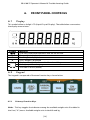
FRONT PANEL CONTROLS ....................................................................................................... 18
6.1
Display ................................................................................................................................... 18
6.2
Keypad ................................................................................................................................... 18
Primary Function Keys ........................................................................................... 18
GENERAL SCALE OPERATION ................................................................................................. 20
7.1
8.
Calibration Troubleshooting ............................................................................... 16
View Calibration Values (F18) ......................................................................................... 16
6.2.1
7.
Menu Structure .......................................................................................................... 8
Weighing An Item .............................................................................................................. 20
RECHARGEABLE BATTERY INFORMATION .......................................................................... 21
[2]
BB 8100 SS Operator’s Manual & Troubleshooting Guide
8.1
Overview ............................................................................................................................... 21
8.2
When To Charge The Internal Battery.......................................................................... 21
8.3
How To Charge The Internal Battery ............................................................................ 21
8.4
How Long To Charge The Internal Battery ................................................................. 21
8.5
Replacing The Battery ....................................................................................................... 22
9.
LEGAL FOR TRADE SEALING .................................................................................................... 23
10.
SPECIFICATIONS.................................................................................................................. 24
11.
SERIAL PORT INFORMATION ........................................................................................... 25
11.1
Serial Port Modes .......................................................................................................... 25
11.1.1
Demand Duplex Mode .......................................................................................... 25
11.1.2
Continuous Duplex Mode .................................................................................... 25
11.1.3
Recognized Host Commands .............................................................................. 25
11.2
OUTPUT STRINGS .......................................................................................................... 26
11.2.1
Text Print Ticket ....................................................................................................... 26
12.
ERROR CODES ...................................................................................................................... 27
13.
Certificate of Calibration .................................................................................................. 28
[3]
BB 8100 SS Operator’s Manual & Troubleshooting Guide
2.
INTRODUCTION
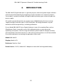
The BB 8100 SS Digital Indicator is a general purpose, industrial grade weight indicator
with advanced functionality for weighing animals and other non-stationary objects.
One model is currently available, distinguishable by display type, enclosure type and
power supply.
All models operate identically, can readout up to 50,000 display divisions and can
supply enough current for up to 4-350 Ω load cells. All setup parameters may be
entered via the front panel keys, including calibration.
If your Model BB 8100 SS Series Digital Indicator is part of a complete floor scale or
Weighbeam Scale, it normally arrives fully calibrated and you may skip to the
operating instructions. Prior to using the indicator, please read this chapter carefully
and completely. Store the manual in a safe and convenient place so it will be available
if you have questions concerning the operation of the scale.
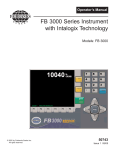
Model: BB 8100 SS
Display: Backlit LCD
Enclosure: Stainless Steel
Power Source: 12V DC, 800mA A/C Adapter or internal 6V rechargeable battery.
[4]
BB 8100 SS Operator’s Manual & Troubleshooting Guide
3.
3.1
INSTALLATION
Preparation
Any precision instrument requires a suitable environment in which to operate as
intended. Please review each of the following prior to installation:
Electrical Power The BB 8100 SS indicator has been designed to operate from 10 to 12
VDC and ships with an AC adapter designed to operate from the local line voltage. To
avoid electrical noise interference and/or stray AC electrical transients, try to operate
the indicator from a circuit separate from any equipment containing inductive devices
such as a contactor coil, solenoid, relay coil, or motor. Be sure to use shielded cables
for the load cell connections (ground shield wire at indicator) and run these cables
away from your AC/DC power cables if possible. In extreme cases, it may be necessary
to install surge suppressors, line conditioners or even UPS (Uninterruptible Power
Supplies) systems (not included).
Environment - Avoid installing the indicator in areas of direct sunlight or high
humidity - Avoid sudden temperature change – if this is unavoidable allow equipment
to ‘soak’ at a constant temperature for at least three hours before use - Ensure that
steady, clean AC power is available to the unit
IMPORTANT: The installer is ultimately responsible to assure that a particular
installation is safe and operable under the specific conditions encountered.
3.2
Connections
The BB 8100 SS typically comes with two five-pin round quick disconnect ports. In
most installations, you will only need to use one of these. It does not matter which
port you use; simply plug in the home run cable to one of the two ports and tighten
the ring screw to ensure a good connection.
In some instances, one of these two ports may be wired to the internal RS-232 port to
allow for the connection of a printer or to a computer. This is typically done by special
request at the time that you order your scale but is a simple field modification should
you desire to modify your indicator. See chapter XREF for more information on
modifying indicator ports.
3.3
Connecting The Power Supply
The BB 8100 SS indicator ships standard with an external AC adapter that can be used
both to operate the unit and charge the internal battery. Simply plug the AC adapter
into the indicator’s DC Power Jack first, and then plug into a standard wall outlet.
[5]
BB 8100 SS Operator’s Manual & Troubleshooting Guide
IMPORTANT: Make sure that the AC voltage at the wall outlet matches the input
voltage marked on the AC adapter.
[6]
BB 8100 SS Operator’s Manual & Troubleshooting Guide
4.
4.1
CONFIGURATION
Overview
The indicator contains two main configuration menus: The Setup (“F”) menu, which
configures the indicator to your weigh platform, and; The User (“A”) menu, which
configures the serial communication port and enables some user options. The Setup
and User menus consist of several menu selections, each with its own sub-menu of
selections or programming procedures. To configure the indicator you must first enter
the appropriate menu mode. Once there, four of the front panel keys become
directional navigators to move around in the menus, and one key is used to save or
SET the selections.
4.2
Accessing The Menus
To access the Setup (“F) menu:
1. Power off the indicator.
2. Locate the slide switch on the rear cover and move it to the opposite position.
NOTE: A metal plate held on by two drilled-head screws may
conceal the slide switch. (In some jurisdictions it is necessary to
seal the indicator to place it “In Service.” These drilled screws
allow for a wire to be passed through them and sealed, thereby
preventing the indicator from being reprogrammed.)
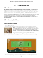
3. Power on the indicator. The display shows” F 1” to indicate that you are in Setup
Menu mode.
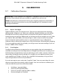
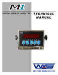
4. Use the navigation keys shown in the figure below to move through the menus.
[7]
BB 8100 SS Operator’s Manual & Troubleshooting Guide
To access the User (“A) menu:
1. Enter the Setup (“F”) menu as described above.
2. Use the right or left directional keys shown below to move right or left in the Setup
(“F”) menu until the indicator shows ” A 1”.
4.2.1
Menu Structure
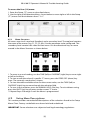
All menus consist of a top level (heading) and a secondary level. The top level contains
the name of the menus (e.g. F1, F2, F3, etc. ) for the parameter to be configured. The
secondary level contains the value for that menu. Use the directional keys to move
around in the Menu Structure as shown below.
1. To move to a new heading, use the TARE (left) or ON/PRINT (right) key to move right
or left in the Menu.
2. To view or edit the value of a specific “F” menu, press the ZERO/OFF (down) key
once. The currently saved value is shown.
3. To view the other available values for the current value, use the TARE (left) or
ON/PRINT (right) key to move through the selection field.
4. To save a new selection, press the ANIMAL HOLD (Set) key .To exit without saving,
press the UNITS (up) key to return to the current “F” menu.
5. Repeat Steps 2 through 5 until the Menu is programmed.
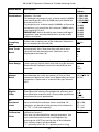
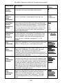
4.3
Setup Menu Descriptions
This section provides more detailed descriptions of the selections found in the Setup
Menu Chart. Factory-set defaults are shown bold and underlined.
IMPORTANT: Some selections are subject to local legal metrology regulations
[8]
BB 8100 SS Operator’s Manual & Troubleshooting Guide
Menu Name
Description
F1
Graduations
Specifies number of full-scale graduations, i.e.
capacity / division.
For example, to program your scale to weigh 5,000lbs
you would set this value to 5000, and you would set
the value of F9 to 1.
To program your scale to weigh 10,000lbs at 2 pound
increments, you would set this value to 5,000lbs and
you would set F9 to 2.
IMPORTANT: Value should be consistent with legal
regulations and environmental limits on the useful
system resolution.
F2
Sampling
Rate
F3
Zero Track
Band
Selects the sampling rate of the indicator. Selections
are in samples per second (Hz).
Possible
Values
500 1,000
1,500 2,000
2,500 3,000
4,000 5,000
6,000 8,000
10,000
12,000
20,000
30,000
40,000
50,000
10, 80
Selects the range within which the scale will
automatically zero. Note that the scale must be in
standstill to automatically zero. Selections are in
displayed in divisions (d).
0
0.5
1
3
5
F4
Zero Range
Selects the range (expressed as a percentage of full
scale capacity) within which the scale may be zeroed.
Note that the indicator must be in standstill to zero
the scale.
100%
1.9%
2%
20%
F5
Motion
Band
Sets the level at which motion is detected. If motion is
not detected, the scale can process a Print or Zero
command. Maximum value varies depending on local
regulations. Expressed as scale divisions per second
(d/s).
0.25, 1,3, 5,
10, 15, 20, 30,
40, 50
F6
Digital
Filter
Averages weight readings to produce higher stability.
The higher the setting, the greater the accuracy but
the slower the response time. Choose the speed that
works best for your application.
F7
Overload
Limit
Selects the desired formula which determines the
point at which the indicator shows overload. All
selections are based on the primary unit selected in
F8 ("FS" = Full scale capacity)
F8
Calibration
Units
Selects the primary unit of measure to be used in the
calibration process.
This also sets the default for normal operation. You
can switch between Pounds and Kilograms by
pressing the UNITS key on the face of the indicator.
This setting simply sets the default.
"1" = primary unit is lb. "2" = primary unit is in kg.
[9]
1, 2,
4 ,8,
16, 32
62, 128
FS
FS + 2%
FS + 1d
FS + 9d
1 = Pounds
2= Kilograms
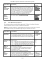
BB 8100 SS Operator’s Manual & Troubleshooting Guide
Possible
Values
1
2
5
Menu Name
Description
F9
Display
Divisions
Determines the desired weight increments. Value
should be consistent with legal requirements.
F10
Decimal
Point
Placement
Sets the decimal point, should you need to weigh in
tenths, hundredths, thousandths of pounds, etc.
0,0.0, 0.00,
0.000,
0.0000, 00
F11
Initial Zero
Setting
Mechanism
(IZSM)
Selects the range (expressed as a percentage of full
scale capacity) within which the scale automatically
zeroes upon power-up (initialization). If you need the
indicator to recall how much weight is on the scale
when you first turn on the scale, set this to zero. This
is useful for grain carts or other scales that always
have weight on them.
Sets the percentage change required for the indicator
to reset and take a new weight. For example, if two
animals accidently jump on the scale and the scale
locks at 3500lbs, the scale will automatically reset
itself if there is a change in weight of +/- x% of
3500lbs..
When calibrating the scale, set this value to “1” to
begin zero calibration. You usually want to make sure
there is nothing on your scale before doing this.
100
0
2
10
20
100
When calibrating the scale, set this value to “1” to
begin Span Calibration. You must place your test
weights on the scale prior to beginning this
sequence. When the sequence begins you will have
an opportunity to enter the amount of weight you are
calibrating your scale with.
When you calibrate the scale at F16 and F17, the
indicator translates the signal from the load cells into
a numeric value. There is one numeric value for ZERO
pounds, and another numeric value for the amount of
weight you used to calibrate the indicator in F17. This
menu allows you to view those numeric values. This is
VERY useful if you ever need to recalibrate your scale
in the field and you do not have test weights. See F19
and F20 for more information.
When you calibrated the scale at ZERO pounds in F16,
above, the indicator assigned a numeric value to
ZERO. You can view the value at F18, above, then
enter it here to mimic ZERO calibration. The scale
must be calibrated first using F16 before this will
work.
Press
ZERO/OFF
to begin
calibration.
F12
SmartSense
Animal
Weighing
F16
Zero
Calibration
F17
Span
Calibration
F18
View
Calibration
Settings
F19
Zero
Calibration
Override
[10]
5, 10, 20, 50,
75,100 (off).
Press
ZERO/OFF
to begin
calibration
Press
ZERO/OFF
to view
values
Press
ZERO/OFF
to begin
procedure
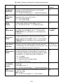
BB 8100 SS Operator’s Manual & Troubleshooting Guide
Menu Name
Description
F20
Span
Calibration
Override
When you calibrated the scale at F17, you entered a
SPAN weight (the amount of your test weights). The
indicator translated that to a numeric value that you
can view at F18. Enter the SPAN value here to mimic
your SPAN calibration. The scale must be calibrated
first using F17 for this to work. Use this procedure
only in an emergency. It is always better to use
certified test weights to calibrate your scale.
This completely erases all of the settings in all of your
“A” and “F” Menus. USE WITH CAUTION.
F21
Reset
Factory
Settings
4.4
Possible
Values
Press
ZERO/OFF
to begin
procedure
Press the
ZERO
button
TWICE to
activate
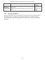
User Menu Descriptions
This section provides more information about the “A” Menu (User Menu) functions.
Default indicator values are shown in bold and underlined.
NOTE: To get to the “A” Menus, simply follow the instructions to enter the “F” menus
and use the arrow keys to scroll left or right until you reach the “A” menus.
Menu Name
Description
A1
Baud Rate
Selects the baud rate for data transmission through
the serial port. (The connection to the serial port is
not installed by default. You must first wire a port to
the internal RS-232 wire block on the mother board.)
A2
Data Bits and
Parity
Selects the number of data bits and parity of serial
transmission.
"8n" = 8 data bits with no parity bit and one stop bit
"7O" = 7 data bits with odd parity bit and one stop bit
"7E" = 7 data bits with even parity bit, one stop bit
"7n" = 7 data bits with no parity bit and two stop bits
Selects when data will be sent out of the serial port
to a printer or computer:
"C" = Continuous mode; send data continuously
"d" = Demand mode; send data when a PRINT
command is issued
from the printer, computer, or indicator.
Actuates the function that illuminates all digit
segments, decimal points, and LCD annunciators in a
test sequence. Pressing the ZERO/OFF key to scroll
down one level begins the test sequence
A3
Mode of
Serial
Transmission
A4
Display
Check
[11]
Possible
Values
1200 2400
4800 9600
19200
8n
7O
7E
7n
C
d
Press
ZERO/OFF
key to begin
sequence
BB 8100 SS Operator’s Manual & Troubleshooting Guide
Menu Name
Description
A5
Disable the
LB/KG key
Allows the lb/kg key to be disabled so that an
operator cannot accidentally press the key and
change the displayed units.
"0" = Disable the lb/kg key "1" = Enable the lb/kg key
A6
Serial Port
Mode
Selects the mode of the RS-232 serial port: Refer to
Appendix B for more information.
"0" = Full Duplex Mode
"1" = Print Ticket Mode
0
1
A7
ID No.
Enable
Allows the ID number to be disabled in the Print
Ticket mode. Valid only when A6 is set to “1”.
"0" = Disable the ID No. "1" = Enable the ID No.
0
1
A8
ID No. Entry
Actuates the function that allows entry of a new ID
No. Valid only when A6 is set to “1”. Pressing the
ZERO/OFF key to scroll down one level begins the
sequence.
0 – 999999
123456
A9
No. of Line
Feeds
Actuates the function that allows entry of the desired
number of line feeds to be printed in Print Ticket
Mode. Valid only when A6 is set to “1”. Pressing the
ZERO/OFF key to scroll down one level begins the
sequence.
Selects the automatic power off time in minutes that
indicator must be inactive before the indicator will
automatically shut off. Setting this value to “OFF “ will
cause the indicator to always remain on.
0 - 99
8
A10
Auto Power
Off Timer
A11
Animal Hold
Mode
A12
Handshake
Enable
A13
Print Header
Activates automatic animal hold mode in which the
weight of the object on the platform is frozen until
the weight is decreased by the percentage of weight
specified in F12. Selects the ‘‘H old’’ mode to use.
‘‘0’’ = Disabled
‘‘1’’ = Automatic H old,
‘‘2’’ = Manual H old w/ display freeze
‘‘3’’ = Peak Animal H old
Enables hardware handshaking for Print Ticket Mode.
Valid only
when A6 is set to “1”.
"0" = Disable Handshaking "1" = Enable Handshaking
Tells MP-20 printer to print the header information.
Valid only when
A6 is set to “1”.
"0" = Do NOT Print Header "1" = Print Header
[12]
Possible
Values
0
1
Off
1, 2, 3, 5 , 8
10, 15, 20, 30
0
1
2
3
0
1
0
1
BB 8100 SS Operator’s Manual & Troubleshooting Guide
Menu Name
Description
A14
Minimum
Hold Weight
When automatic hold mode (A11) is enabled, sets the
minimum
weight that can be held; expressed in scale divisions
(“d”).
4.5
Possible
Values
1, 2, 5 , 10,
20
50, 100, 200,
500,
1000
Exiting The Menus
Exit the configuration menus by moving the slide switch on the rear of the indicator to
its original position. The display will go through a digit check, and then settle into
Normal Operating mode. All front panel keys will now return to their normal mode of
operation.
[13]
BB 8100 SS Operator’s Manual & Troubleshooting Guide
5.
5.1
CALIBRATION
Calibration Overview
IMPORTANT: If your indicator was shipped as a complete scale, then calibration is not
necessary. Please check with your installer or supplier if you are unsure.
NOTE: B and B Scales recommends having your weighing equipment checked by a
qualified scale technician at least once a year depending on its intended use and
working environment.
5.1.1
Before You Begin
Digital indicators work on internal counts. They do not inherently know anything
about pounds, kilograms, etc. When you calibrate a digital indicator, you are telling
the indicator how many internal counts are equal to zero pounds and how many
internal counts are equal to 500 pounds (or however much test weight you use). After
you “define” 0lbs and 500lbs, the internal logic is able to convert counts to pounds
across the entire capacity of the scale. It is a good practice to try to calibrate the
indicator with an amount of weight that is close to what you will actually be weighing.
If you are weighing cattle, for example, you will get more accurate readings if you use
at least 1200lbs of test weights.
5.1.2
Test Weights
Certified scale companies are required to use test weights that are inspected and
certified annually by their local Department of Weights and Measures (usually part of
the State Dept. of Agriculture). If you are planning to sell / trade / auction / barter any
commodity (including animals) based on its weight, you are required to have your
scale certified and “Placed in Service” by a certified scale company or by your local
Dept. of Agriculture in almost all jurisdictions.
If you do not require your scale to be “Legal for Trade,” here are some ideas for some
common items that are routinely sold by weight. You can use these to calibrate your
scale provided that you know what they weigh:
•
•
•
•
Salt Blocks (typically 50lbs)
Sacks of Feed (typically 50lbs)
Sacks of Concrete (typically 50lbs or 80lbs)
Exercise Weights (as marked)
[14]
BB 8100 SS Operator’s Manual & Troubleshooting Guide
The indicator requires two types of calibration: zero and span. Zero calibration (F16)
requires the scale to be empty (nothing on scale) and the span calibration (F17)
requires known test weights. After a successful calibration, you should record all
calibration values using the F18 View Calibration procedure. In the unlikely event that
any calibration value is lost, the setup menu makes provisions for re-entering these
values via F19 and F20; thus eliminating the need for re-calibration with test weights.
NOTE: This section assumes that the indicator is in Setup (“F”) Menu mode. If the
indicator is not in Setup Menu mode, refer to previous section for instructions.
5.2
Zero Calibration (F16)
1. While in the Setup mode, scroll to "F 16", then scroll down once using the ZERO/OFF
key to enter zero calibration menu. The display will momentarily show "C 0" followed
by a value. This value is the internal A/D count and can prove useful when trying to
troubleshoot setup problems.
2. After making sure that there are no test weights on the platform, press the ZERO key
to zero out the displayed value. The indicator should be stable at 0 and should not
jump around. If you cannot zero the indicator at F16, check your load cell connections
and try again. This is usually a load cell issue.
3. Press the ANIMAL HOLD key to save the zero point value. The display will show
"EndC0" momentarily, and then revert back up to F16. At this time, proceed to the F17
span calibration to complete indicator calibration.
5.3
Span Calibration (F17)
1. While in the Setup mode, scroll to "F 17", then scroll down once using the ZERO/OFF
key to enter span calibration menu. The display will momentarily show "C 1" for the
span calibration point, followed by a value with one flashing digit. This value will be
zero with the Decimal Point parameter selected in F10.
2. Place the test weights in the center of the weighing platform.
3. Use the four directional keys to change the displayed value to the actual test weight
value. Increase the flashing digit by pressing the UNITS key. Decrease the flashing digit
by pressing the ZERO/OFF key. Pressing the TARE key or the ON/PRINT key will change
the position of the flashing digit.
4. After entering the exact value, press the ANIMAL HOLD key to save the value. If the
calibration was successful, the display will show "EndC1" momentarily, and then revert
back up to F17
5. At this time it is suggested that the calibration values be recorded for future use (see
next section).
[15]
BB 8100 SS Operator’s Manual & Troubleshooting Guide
5.3.1
Calibration Troubleshooting
If the calibration was not successful, one of the error messages below will appear. Take
the indicated action to correct the problem, then perform a new calibration.
"Err0" - The calibration test weight or the keyed-in weight is larger than the full
capacity of the scale. Change the calibration test weight or check the input data.
"Err1" - The calibration test weight or the keyed-in weight is smaller than 1% of the
full capacity of the scale. Change the calibration test weight or check the input data.
Remember, the more weight you can use to calibrate your scale, the more accurate it
will be.
"Err2" – There is not enough signal from the load cells to establish a proper calibration.
Most common causes include incorrect load cell wiring, a mechanical obstruction or a
faulty (damaged) load cell or junction box.
•
•
•
•
•
5.4
Check to make sure that the arrows on the load cells are all pointing the
same direction (it does not matter if they are pointing up or down as long as
they are all the same.)
Check the connections in your junction box.
Try switching the white and green wire on the cable that connects the
junction box to the indicator. This is a frequent cause of this error.
Check that the feet on the load cells are not preventing the load cell from
deflecting.
Rarely, a wire will come loose inside the indicator. Remove the back panel of
the indicator and make sure that the quick disconnect ports are properly
wired into the wire block on the motherboard.
View Calibration Values (F18)
Note: The values displayed in this procedure are valid only after a successful
calibration has been performed using F16 and F17
1. While in the Setup mode, scroll to "F 18", then scroll down once using the ZERO/OFF
key to enter View calibration menu.
2. The display will show the information listed on your calibration certificate at the
back of this manual. The code will display briefly followed by the value. Press any key
to continue down the list. At the completion of the list, the indicator reverts back up to
F18.
5.4.1
Key-In Zero Calibration Value (F19)
Note: This procedure is intended for emergency use only in the case of non-volatile
memory loss.
A valid zero calibration value, obtained from a successful F16 calibration procedure,
must be used. 1. While in the Setup mode, scroll to "F 19", then scroll down once using
[16]
BB 8100 SS Operator’s Manual & Troubleshooting Guide
the ZERO/OFF key. The display will momentarily show "CAL 0", followed by a value of
zero 2. Use the four directional keys to enter in the actual zero calibration value. 3.
After entering the exact value, press the NET/GROSS key to save the value. The display
will show "E CAL 0" momentarily, and then revert back up to F19.
5.4.2
Key-In Span Calibration Value (F20)
Note: This procedure is intended for emergency use only in the case of non-volatile
memory loss. Valid span calibration values, obtained from a successful F17 calibration
procedure, must be used.
1. While in the Setup mode, scroll to "F 20", and then scroll down once using the
ZERO/OFF key. The indicator will prompt you to enter the span calibration data from
the Calibration Certificate at the back of this manual.
2. Use the four directional keys to enter in the actual calibration value
3. After setting the exact value, press the NET/GROSS key to save the value.
4. If the entered values are entered successfully, the display will show "E CAL 1"
momentarily before reverting back up to F20.
[17]
BB 8100 SS Operator’s Manual & Troubleshooting Guide
6.
6.1
FRONT PANEL CONTROLS
Display
This model utilizes a 6-digit LCD (Liquid Crystal Display). The table below summarizes
the display annunciators.
Symbol
0
T
N
G
Lb, kg
6.2
Meaning
True zero, within the tolerances that are set for zero.
Tare weight is displayed
Net Weight is displayed
Gross Weight is displayed
Displayed weight is measured in Pounds or Kilograms
Battery requires recharging
The scale is at rest (stable).
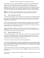
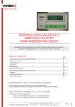
Keypad
The keypad is composed of fourteen function keys shown below.
6.2.1
Primary Function Keys
Units – This key toggles the indicator among the available weight units if enabled in
the User (“A”) menu. Available weight units include lb and kg.
[18]
BB 8100 SS Operator’s Manual & Troubleshooting Guide
Zero/Off - This key sets the indicator to display zero provided the following conditions
are met:
1. The indicator is displaying Gross weight.
2. The displayed weight is within the zero reset range that is programmed in
F4 of the Setup (“F”) Menu.
3. The scale is not in motion.
4. The scale is not in overload (see Appendix D for error codes). When held
for five seconds, shuts the unit off.
Animal Hold - This key toggles turns on and off the manual Animal Hold provided
that the Animal Hold function is programmed in manual mode (A11).
Tare - This key is used to establish a Tare provided the following conditions are met:
1. The indicator is not at or below Gross zero.
2. The scale is not in motion.
3. The scale is not in overload (see Appendix D for error codes).
On/Print – When the unit is off, turns the unit on. When the unit is on, this key is used
to send weight information out to the serial port provided the following conditions
are met:
1. The scale is not in motion.
2. The scale is not in overload (see Appendix D for error codes).
[19]
BB 8100 SS Operator’s Manual & Troubleshooting Guide
7.
7.1
GENERAL SCALE OPERATION
Weighing An Item
1. Select the desired weighing unit by pressing the UNITS key until that unit is
indicated on the display.
2. If necessary, press the ZERO/OFF key to obtain a weight reading of zero.
3. If weighing an item in a container, place the empty container on the scale’s platter
and, after allowing the weight indication to stabilize, press the TARE key. The display
shows zero weight and turns the NET annunciator on
4. Place the object to be weighed on the scale’s platter and allow the weight
indication to stabilize. If the item weight exceeds the scale’s weight capacity, it
displays “oooooo”.
5. Read the weight shown on the display. If you have established a tare, you may
toggle between the gross weight and the net weight by pressing the NET/GROSS key
WEIGHING ANIMALS Here are some tips when using the automatic hold function
(A11) to weigh animals:
•
•
•
Use a setting of “8” or lower for F6 (Digital Filter). Using higher settings will
likely cause the indicator to lock onto the wrong weight prematurely.
Use the Motion Band setting (F5) to adjust for the motion of the loads. If the
setting is too low, then the indicator may never lock onto a weight. If the
setting is too high, the indicator may not lock the weight accurately.
Another approach is to completely disable automatic hold (A11) and use a
large setting for Digital Filter (F6).
[20]
BB 8100 SS Operator’s Manual & Troubleshooting Guide
8.
8.1
RECHARGEABLE BATTERY INFORMATION
Overview
IMPORTANT: Your scale contains an internal lead-acid rechargeable battery. Before
using the indicator for the first time, please charge the battery overnight.
The indicator’s battery should operate for about 40 hours if connected to a four load
cell platform and left on continuously. Greater usage times can be achieved by
selecting an appropriate Auto Power Off Period under A10 of the User Menu.
The battery can be charged while ON or OFF and the indicator can be operated while
it’s charging unless the state of charge is very low.
8.2
When To Charge The Internal Battery
The best time to charge the sealed lead-acid type battery is any time the indicator is
not in use. You need not wait for the Low Battery Indication – in fact it’s best that you
don’t. Charging the battery when not in use keeps the battery “fresh” and is the
recommended way to manage it. When the battery needs to be charged, the Low
Battery Indicator will slowly flash in the upper left hand corner of the display. The
indicator may be used for an additional 10 minutes without damage to the internal
battery. Halfway thru this time, the Low Battery Indicator will start to flash quickly.
Eventually, the indicator will display “bAtt” for 2-3 seconds and then automatically
power down. It is imperative that you charge the battery at this time to avoid
damage.
8.3
How To Charge The Internal Battery
1. Connect the charger (AC Adapter 12 VDC, 800mA) to the scale, and then plug the
charger into an AC outlet. Make sure that the AC voltage appearing at the wall outlet
matches the input voltage marked on the AC adapter.
2. After the charging period expires, unplug the charger from the AC outlet, then from
the scale. The scale is now ready for use under its own battery power. NOTE: The
charger may be left connected to the scale indefinitely without damage to the internal
battery.
8.4
How Long To Charge The Internal Battery
In general, the battery should be allowed to charge a minimum of 1.5 hours for every
hour of use. If you discharge the battery below 50% and do not allow the proper time
for charging, you may start to notice a decline in the usage period. This is normal and
eventually the battery must be replaced.
[21]
BB 8100 SS Operator’s Manual & Troubleshooting Guide
8.5
Replacing The Battery
The recommended practice when removing the battery is to disconnect the ground
connection (black) first, then the red terminal. This ensures that a short circuit will not
occur from a battery lead or fuse lead touching the grounded housing while
disconnecting the other terminal. Similarly, the ground should be connected last
when installing a new battery.
IMPORTANT: The US government has classified the internal battery as hazardous
waste. Do not discard battery in a landfill. An automotive store or a local waste agency
may accept the batteries for recycling. Contact the manufacturer for more information.
[22]
BB 8100 SS Operator’s Manual & Troubleshooting Guide
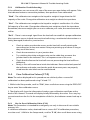
9.
LEGAL FOR TRADE SEALING
This indicator can be sealed for commercial (Legal for Trade) applications as follows.
1. Power off the indicator.
2. On the back of the indicator, locate the setup/calibration switch cover.
3. Thread a wire security seal through both drilled head screws securing the calibration
switch cover as well as the single drilled head screw holding on the rear panel.
[23]
BB 8100 SS Operator’s Manual & Troubleshooting Guide
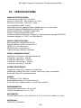
10. SPECIFICATIONS
ANALOG SPECIFICATIONS
Full Scale Input Signal ±3.125 mV/V
Minimum Sensitivity - Non trade 0.3 V / grad
Minimum Sensitivity - H-44 0.6 V / grad
Input Impedance 30M , typical
Internal Resolution Approximately 280,000 counts @ 2mV/V input
Display Resolution 50,000 display division max
Measurement Rate 10 Hz/80 Hz selectable
System Linearity Within 0.02% of FS
Calibration Method Software Calibration, with long term storage in EEPROM
Excitation Voltage +4.7 VDC, 4 x 350 load cells
DIGITAL SPECIFICATIONS
Microcontrollers Winbond W78E516
Program Memory 64K x 8, internal to C
SRAM: 512 x 8, internal to C
EEPROM: 256 x 8, external to C
Digital Filtering Software selectable
SERIAL COMMUNICATIONS
Serial Port Full Duplex, selectable Baud rate
8 data bits, no parity, 1 stop bit
7 data bits, odd parity, 1 stop bit
7 data bits, even parity, 1 stop bit
7 data bits, no parity, 2 stop bits
OPERATOR INTERFACE
Display 0.8" (20 mm) 7-segment, LCD, 6 Digit
Additional Symbols Net, Gross, Stable, Tare, lb, kg, Zero, Low battery
Keyboard 5-key flat membrane panel
POWER
AC Adapter 12 VDC, 800 mA
Rechargeable Battery 6 V, 3Ah lead-acid
DC Power Consumption 70mA + 13mA/350 Load Cell
ENVIRONMENTAL
Operating Temperature –10° to +40 C
Storage Temperature -25° to +70 C
MECHANICAL
Overall Dimensions (L x W x H) 9.0" x 5.5" x 2.9" (231mm x 140mm x 72mm)
APPROVALS
NTEP COC # 94-080A2
[24]
BB 8100 SS Operator’s Manual & Troubleshooting Guide
11. SERIAL PORT INFORMATION
11.1 Serial Port Modes
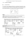
11.1.1
Demand Duplex Mode
The Demand Duplex Mode (A3 = ‘d’, A6 = ‘0’) provides a two way serial transmission
mode In this mode, the output information is transmitted on demand; either by
pressing the PRINT key on the indicator’s front panel or upon receiving a recognized
command from a host device (i.e. computer). NOTE: Ensure that your cabling contains
the proper handshaking.
11.1.2
Continuous Duplex Mode
The Continuous Duplex Mode (A3 = ‘C’, A6 = ‘0’) provides a two-way serial
transmission mode. In this mode, the output information is transmitted continuously
making it a popular choice for remote displays and other remote devices requiring a
constant data stream. The transmission automatically occurs at the end of each display
update. The indicator will react upon receiving a recognized command from a host
device.
11.1.3
Recognized Host Commands
These commands apply to both demand and continuous duplex modes.
“P” - This command is sent to the indicator to print the indicated display. The indicator
will not respond if the scale is in motion, positive overload or negative overload.
“Z” - This command is sent to the indicator to zero the scale. The indicator will not
respond if the scale is in motion, positive overload or negative overload. The indicator
will also not respond if it is not in gross mode or within the zero range specified in F4
of the Setup Menu.
“T” - This command is sent to the indicator to tare the scale. The indicator will not
respond if the scale is in motion, positive overload or negative overload. The indicator
will also not respond if it displaying a negative gross value.
“G” - This command is sent to the indicator to switch to gross mode. The indicator will
not respond if the scale is in motion, positive overload or negative overload.
“N” - This command is sent to the indicator to revert to net. The indicator will not
respond if the scale is in motion, positive overload or negative overload. The indicator
will also not respond if a tare has yet to be established.
“C” - This command is sent to the indicator to toggle among the configured units of
measure.
[25]
BB 8100 SS Operator’s Manual & Troubleshooting Guide
11.2 OUTPUT STRINGS
11.2.1
Text Print Ticket
The Text Print Ticket is designed specifically for a serial printer. Ensure that A6 is set to
‘1’. For printers with limited buffers, this mode supports DTR pin handshaking. The DTR
pin from the serial printer is wired to the indicator’s RXD pin which then functions as a
CTS pin. Refer to the printer’s user manual to confirm which pin is the DTR pin.
NOTES:
1. The TARE and NET fields are not printed unless a tare has been established in the
system.
2. The ID number field is not printed if it is disabled in A7 of the User Menu.
STRING FORMAT 1 (Condec Demand String) String Format 1 is designed for two-way
communication. Ensure that A3 is set to ‘d’ and A6 is set to ‘0’.
STRING FORMAT 2 (Condec Continuous String)
String Format 1 is designed for one-way communication. Ensure that A3 is set to ‘C’
and A6 is set to “0.”
[26]
BB 8100 SS Operator’s Manual & Troubleshooting Guide
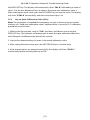
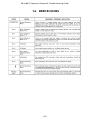
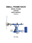
12. ERROR CODES
[27]
BB 8100 SS Operator’s Manual & Troubleshooting Guide
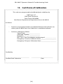
13. Certificate of Calibration
This scale was programmed and calibrated prior to delivery by
B&B Scales LLC
5386 Santa Teresita Dr.
Santa Teresa, NM 88008
New Mexico Department of Agriculture License No. 00546
As follows:
Scale was pre-programmed but not calibrated because the indicator was
sold as part of a Build Your Own Scale Kit or a standalone indicator.
Scale was calibrated as follows:
Type of Scale_____________________
Calibrated Capacity _______________
Resolution ______________________
NIST Class F Cert. Test Weights used during cal: _______________
Emergency F19 (zero) Calibration Value: _____________________
Emergency F20 (span) Calibration Value: _____________________
Certified by:
_________________________________
Certified Scale Technician
______________________________
Date
[28]
BB 8100 SS Operator’s Manual & Troubleshooting Guide
[29]
B & B Scales LLC
www.bbscales.com
[email protected]
575-332-4111