1
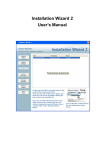
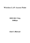
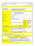
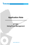
Installation Wizard 2 User’s Manual Rev. 1.1a, July, 2014 Contents Chapter 1 Installation................................................................................ 1-2 1.1 Software Installation ..................................................................... 1-2 Chapter 2 Using Installation Wizard 2 ...................................................... 2-6 2.1 User Interface............................................................................... 2-6 2.1.1 Functional Buttons .............................................................. 2-11 2.2 Smart Setup ............................................................................... 2-13 2.2.1 System Setup ..................................................................... 2-14 2.2.2 Change Host Name............................................................ 2-15 2.2.3 PPPoE Setting ................................................................... 2-16 2.2.4 DDNS Setting ..................................................................... 2-18 2.2.5 Wireless Setting ................................................................. 2-21 2.3 Manual Setup ............................................................................. 2-30 2.3.1 System Setting ................................................................... 2-31 2.3.2 Network Setting .................................................................. 2-34 2.3.3 Port Setting ........................................................................ 2-39 2.3.4 DDNS Setting ..................................................................... 2-40 2.3.5 Wireless Setting ................................................................. 2-43 2.3.6 Apply to selected device .................................................... 2-60 2.4 Access Information..................................................................... 2-62 2.5 Upgrade Firmware(s) ................................................................. 2-66 2.5.1 Device Information ............................................................. 2-67 2.5.2 Firmware Information ......................................................... 2-68 2.5.3 Select Firmware ................................................................. 2-68 2.5.4 Start Upgrade ..................................................................... 2-70 2.5.5 Upgrading Firmware for Multiple Cameras ......................... 2-71 2.6 Restore Default .......................................................................... 2-74 Revision History Rev. 1.0: Initial release. Rev. 1.1: Updated description for CD autorun program, supported ASCII code, and wireless connection processes. Rev. 1.1a: Added description for the Search function. 1 Chapter 1 Installation 1.1 Software Installation The following are steps for the software installation. STEP 1: Put the Installation disk into your optical drive, and the product utilities autorun should start automatically. Figure 1-1 Installation Wizard 2 Installation Window If the installation does not start, click on the “Start” button to unfold at the lower left corner of your Windows desktop, open “My Computer” and double-click on the optical drive icon. The auto run screen should appear as shown above. Click on Software Utilities. NOTE: Installation Wizard 2 will be shorted as IW2 in the following discussions throughout this document. 1-2 STEP 2: Click on Installation Wizard 2 on the Software Utilities menu. Figure 1-2 Software Utilities Window STEP 3: Click on Installation Wizard 2 to start installation. Figure 1-3 Installation Wizard 2 Window 1-3 Figure 1-4 Installation Wizard 2 Installation Window STEP 4: The License Agreement page will prompt. Please read the license agreement first, and then click on “I Agree” to continue the installation process. The Installation Options page will prompt as shown below. The “Create shortcut on desktop” checkbox is selected by default. Deselect the checkbox if you do not prefer a desktop shortcut. Click on the “Next” Button to proceed. Figure 1-5 Select components to install STEP 5: Select the installation directory for this application software and click on “Install” button. You can also change the installation directory using the “Browse…” button. Click on the “Install” button to continue. 1-4 Figure 1-6 Destination Location for Installation STEP 6: The installation will start and a progress bar will display on the dialog. Click on the “Close” button when the process is completed (Figure 1-7). Figure 1-7 Installation is Completed NOTE: You may also download the latest revision of IW2 from VIVOTEK’s website. 1-5 Chapter 2 Using Installation Wizard 2 2.1 User Interface Figure 2-1 Analyze network environment The Installation Wizard 2 automatically analyzes and categorizes your network environment into 6 typical types. They include: Private fixed IP, Private DHCP, PPPoE, Public fixed IP, Public DHCP and No Connection to Internet. Once you run the Installation Wizard 2 program, it will first analyze your network and display your network environment type as shown above. For example, if there is a DHCP server on your LAN, using DHCP function to set up the device is easier than the other options. 2-6 Click on the “Next” button to continue. After a brief search, the Device Selection window will prompt as shown below. Every network cameras connected in the local network will be listed if DHCP service is present and they are assigned with IP addresses. On this window, most of the functional buttons will not be available until you click to select a camera from the list. Select a camera and click on the double-arrow button to display more functional buttons on the left of the screen. They include: ”Manual Setup,” “Access Information,” “Upgrade Firmware(s),” “Restore Default” and “About IW2”(Figure 2-3). Figure 2-2 User interface of Installation Wizard 2 IW2 allows you to setup one device at one time and upgrade the firmware of multiple devices (of the same model) at the same time. You can use the Shift key and left mouse click to select multiple cameras. If you selected different models, then the “Upgrade Firmware(s)” button will be disabled. 2-7 Figure 2-3 IW2 with All Functional Buttons Search: You can enter a complete or incomplete model name, MAC address, or IP address of cameras to search for those matching the search condition. For example, you can enter “IP” in the search field only. All models having a name starting with IP will be listed. To end the search process, remove all characters from the search entry field. NOTE: You may also see NR, ND (NVR) series, ST7501, VAST, VIVOTEK’s PoE managed switches, and Matrix stations on the IP list. However, their presence 2-8 is for reference only. To access these stations, open a management session with their IPs using software utilities such as the LiveClient or PlayBack. The management stations running the 32-channel ST-7501 software are not shown on the IP list. As shown below, functions provided with the IW2 can not apply to a VAST station. 2-9 Figure 2-4 Refresh devices The “Refresh Devices” button polls the local network for all connected cameras, video servers, and/or ST7501/VAST servers. Refreshing the device list will take several seconds. If you want to establish a management session with a device, double-click on it, and a session on the IE browser will start. 2-10 2.1.1 Functional Buttons Figure 2-5 Function buttons This function guides you through the important configuration steps using automated process tools. Click on this button to modify the setting of the selected devices. For more details, please refer to Section 2.3 for more information 2-11 Click on this button to upgrade the firmware of the selected devices. For more detail, please refer to 2.5 Upgrade Click on this button to get the access information, it will show you the IP Address information, DDNS information, UPnP Port Forwarding information, and PPPoE connecting information. For more detail, please refer to 2.4 Access Information. Click on this button to restore the selected device to factory defaults. Click on this button to get version information of the Installation Wizard 2. 2-12 2.2 Smart Setup Click to select one or more devices in the selection list, the “Smart Setup” button will be enabled. Click on it to configure the settings of the selected device. The IW2 will attempt to connect to the selected device. If user name and password have been configured on the device (network camera), a confirm box will prompt. Enter User name and Password for access to the device. If you fail three times, the IW2 will display a warning message and abort the connection. Figure 2-6 Authentication Dialog Window Figure 2-7 Authentication error 2-13 2.2.1 System Setup Once connected to the device, the IW2 will display the system setting page. Figure 2-8 System setting page Click to cancel the setup progress. Click to keep the present setting and proceed. 2-14 2.2.2 Change Host Name The “Hostname” is displayed on a device’s web browser homepage and on the title bar with every video feeds from the device. The maximum string length is 40 characters or 13 characters in double-byte-character- systems like Chinese or Japanese. Although some cameras support Unicode, the maximum string length depends on the characters you enter, and the actual length may be less than 20 alphabetic characters. A warning message will prompt if you enter invalid characters that are not supported by the ASCII code. Figure 2-9 Host Name Error Message 2.2.2.1 Change root password To change the administrator’s password, type identical passwords in both “Password” and “Confirm Password” text boxes. The maximum length of password depends on the camera you connected. A warning message will prompt if you enter invalid characters that are not supported by the ASCII code. When done, click on the Next button to proceed. The User name for the administrater login is “root,” and can not be changed. 2-15 2.2.3 PPPoE Setting During the initiation process the IW2 automatically analyzes your network environment, and will prompt you for configuring PPPoE connection. If you attach cameras to a local area network, the PPPoE prompt might not appear. If your network connection is made via PPPoE, click Yes to begin configuration. 1. On the Internet Account Settings page, enter PPPoE username and PPPoE password distributed to you by your ISP. 2. You can use the Test button to verify the connectivity via PPPoE. 2-16 The IW2 will try to connect via the cable/DSL modem with your ISP server. 3. Upon successful connection, the following message will prompt. 4. Continue your configuration using the Next button. If PPPoE service is not valid or you entered the wrong user name/password, the following message will prompt. Consult your ISP for correct PPPoE setup. 2-17 2.2.4 DDNS Setting Figure 2-10 DDNS Setting The DDNS (Dynamic Domain Name Service) is a method of keeping a domain name mapping to a dynamic public IP address. In many cable/DSL connections, a dynamic public IP address is assigned for every connection request. After you set up your DDNS service, the DDNS service provider will automatically update your connection information if the public IP address has been changed. You have to enter the “Host name”, “E-Mail address”, “Key” and “Confirm key” to initiate the DDNS. The “Host name” should be 1 to 64 character(s) long, and the “E-Mail address” will be used to receive some DDNS 2-18 information, please enter a valid e-mail address. If you have a fixed public IP, or you don’t plan to access the camera via Internet, you may deselect the “Enable DDNS” checkbox to disable the DDNS function. If you forgot your DDNS key (password), you can enter the Hostname and E-mail address first, and then click on the “Forget Key” button. The forgotten key will be delivered to you via an e-mail by the DDNS provider. Make sure the host name has not been registered before, you should click on the “Register DDNS” button to proceed. The DDNS provider usually has a minimal time interval between registrations. For the Safe100.net server, the interval is about 10 minutes. If the host name has already been used, the following messages will prompt. If you want to use another DDNS server provider other than safe100.net, you can click on “Advanced Information” to change the DDNS provider. There are two check circles for service providers in the advanced setting, one is saf100.net (by VIVOTEK) and another is Custom DDNS server. If you choose the Custom DDNS server, you have to manually enter the Server address and 2-19 the DDNS domain name as shown below. You can then click the Next button to proceed. Figure 2-11 Advanced DDNS Setting When successfully registered to a DDNS provider, the following messages will prompt: 2-20 2.2.5 Wireless Setting Figure 2-12 Wireless Setting Confirm Box The above message will prompt ONLY when you are working with a model that comes with wireless connection capability. It allows you to configure the wireless connection setting. Click Yes, and you will enter the Wireless configuration screen. The IW2 borrows wireless camera’s networking capability to detect and accomplish wireless configuration. No wireless adapter card is required on your PC running the IW2 utility when using the Smart Setup function. After a brief search, all reachable APs at the network camera’s installation site will be listed. Their key information, including SSID (Service Set Identifier), mode, Channel, Encryption, and Signal Length will also be detected. 2-21 Figure 2-13 Wireless Setting Click to select a preferred AP and click Next to proceed. Click Yes to connect to a wireless AP. You will be prompted if WEP or WPA-PSK encryption key is required. 2-22 Figure 2-14 Wireless Access Authentication Depending on the quality of your wireless connections, you may need to retry the connections. 2-23 When successfully connected, the below message will be displayed. Figure 2-15 Wireless Connection Success Information 2-24 If the connection fails, a different message will display. Figure 2-16 Wireless Connection Failed When the wireless connection is successfully made, you can unplug your LAN cable. Click Apply on the following screen to end the Smart Setup process. Figure 2-17 Apply Settings 2-25 The Apply process will take several seconds. Your network camera will automatically reset during the process. The Access Information page will prompt, showing access links to the network camera. Figure 2-18 Access Information 2-26 The Access from Home provides an access link from the PC where you run the IW2 to the network camera. The Access from Internet provides an access link to the network camera via Internet. The Access from Cellphone provides an access link to the network camera’s MPEG4 video stream. The default is using stream #3 in MPEG-4 format, which is usually set as a minimized-size streaming for remote monitoring via 3GPP-compatible cell phones or other mobile devices. Running over the RTSP protocol, it should be noted that most players on cell phones do not support RTSP authentication. The firmware default for RTSP authentication is disabled. Error Messages: Some error messages might appear due to network problems or inappropriate configuration. Shown below are the messages and suggestions to resolve the problems: DHCP service is not present in your local network. Consult your network administrator for correct configuration. If you need to utilize a direct connection with a PC using a cross cable, the default password for a VIVOTEK network camera is <169.254.0.99.> If there are multiple cameras in your network, they will be assigned with addresses starting from 169.254.0.99, and the IP addresses will be determined by the MAC address of each camera. A camera that comes with a larger MAC address number will be assigned a larger IP address number. You router does not have specific ports opened for routing access from Internet via UPnP ports. Consult your network administrator for more information. 2-27 Figure 2-19 Error Messages This message might prompt if you use PPPoE configuration and the IP has changed after a system reboot. You may use DDNS service to replace the non-static IP. Preserving Access Information Add to My Favorite: The access links created by IW2 will be added to your IE browser’s favorites. Figure 2-20 Access Information Saved to My Favorites Export to Desktop: An HTML file containing the access links will be placed on your desktop. Double-click to open the HTML record. 2-28 Figure 2-21 Access Information in HTML Advanced Information: Hexadecimal or ASCII. Figure 2-22 Advanced Information Click on the Advanced Information button to reveal more information about the current connection settings. 2-29 2.3 Manual Setup IMPORTANT! Write down the fixed IP or the IP address acquired through a DHCP service for your camera before you proceed. This IP will be necessary if you need to configure wireless network connections afterwards. When you select one device in the selection list, the “Manual Setup” button will be enabled. Click on it to modify the settings of the selected device. The IW2 will attempt to connect to the selected device. If user name and password have been configured on the device, a confirm box will prompt. Enter User name and Password for access to the device. If you failed three times, the IW2 will display a warning message (see below) and abort the connection. Figure 2-23 Authentication Dialog Window 2-30 Figure 2-24 Authentication error 2.3.1 System Setting After connected to the selected device, the Installation wizard 2 will switch to system setting page as shown in Figure 2-25. 2-31 Figure 2-25 System setting page Click to cancel the setup progress. Click to keep the present setting and proceed. 2.3.1.1 Change Host Name The “Hostname” is displayed on a camera’s web browser homepage and is displayed on the title bar with every video feeds from the camera. The maximum string length is 40 characters or 13 characters in double-byte-character- systems like Chinese or Japanese. Although some devices support Unicode, the maximum string length depends on the 2-32 characters you enter, and the actual length may be less than 20 alphabetic characters. A warning message will prompt if you enter invalid characters that are not supported by the ASCII code. Figure 2-26 User Name Error Message 2.3.1.2 Change root password To change the administrator’s password, type the new password in both “Password” and “Confirm Password” text boxes identically. The maximum length of password depends on the server you connected. A warning message will prompt if you enter invalid characters that are not supported by the ASCII code. The default administrator name is “root,” and this name can not be changed. 2.3.1.3 Adjust date and time Figure 2-27 Date/Time setup There are three ways to adjust system date and time: 1. "Synchronize with computer time": The easiest way is to make device synchronized with the computer running IW2. 2-33 2. “Set date and time manually”: Set the date and time manually by entering new values. Notice the format in the related field while typing. 3. “Synchronize to network time server automatically”: Make device automatically synchronized with time servers over the Internet every hour. Note that the NTP time server setting is made through a browser management session with the network camera. The configuration is found in System -> System Time -> NTP server. If you want to keep the current date and time, please choose “Keep current date and time”. 2.3.2 Network Setting The IW2 can help you setup the network connection with LAN or PPPoE. After you clicked on the “Next” button from the System page, the IW2 will prompt you for making the PPPoE setting (Figure 2-28). If you want to connect your network camera to Internet via PPPoE, please click on “Yes” to start the PPPoE setting process, or click on “No” to invoke the LAN setting. NOTE: If you accidentally click Yes while you do not want to set up network on PPPoE, close the General Settings window and start again. Figure 2-28 Choosing the network type 2-34 2.3.2.1 PPPoE Setting Figure 2-29 Network Setting for PPPoE If you click on “Yes” in the “Network Type” dialog, you will enter the PPPoE setting page. Enter “PPPoE username” and “PPPoE password” provided by your Internet Service Provider. If you do not know the account information, please contact your ISP. After entering the account information, please click on the “Next” button to continue. The maximum length of user name is 128 characters and 64 for the password. A warning message will prompt if you enter invalid characters that are not supported by the ASCII code. During the initiation process the IW2 automatically analyzes your network environment, and will prompt you for configuring PPPoE connection. If you 2-35 attach cameras to a local area network, the PPPoE prompt might not appear. If your network connection is made via PPPoE, click Yes to begin configuration. 1. On the Internet Account Settings page, enter PPPoE username and PPPoE password distributed to you by your ISP. 2. You can use the Test button to verify the connectivity via PPPoE. The IW2 will try to connect via the cable/DSL modem with your ISP server. 3. Upon successful connection, the following message will prompt. 2-36 4. Continue your configuration using the Next button. If PPPoE service is not valid or you entered the wrong user name/password, the following message will prompt. Consult your ISP for correct PPPoE setup. 2-37 2.3.2.2 LAN Setting If you click on “No” in the “Network Type” dialog, you will enter the Network Setting page. In this page, you can manually enter a static IP, subnet mask, default gateway, primary DNS server, and secondary DNS server. Please consult your network administrator for networking information. Figure 2-30 Network Setting for LAN You can set up the network with DHCP or fixed IP: 1. DHCP: Select the "Get IP by DHCP Server automatically" checkbox will force the device to renew its IP address whenever it reboots, and the related network configuration is provided by the DHCP server. 2. Fixed IP: If you want the device to use a fixed IP, please deselect the "Get IP by DHCP Server automatically" checkbox and assign a valid IP address, subnet mask, default gateway and DNS server for the device. 2-38 2.3.3 Port Setting If your device is located behind the router (such as private fixed IP or private DHCP) and you want to access the device through the Internet, your router must be configured first. The UPnP port forwarding will configure your router automatically, but if your router does not support UPnP, you need to manually configure the port numbers and port forwarding feature. The IW2 will detect whether your router support UPnP or not. If your router supports UPnP, IW2 will automatically select an apporpriate “UPnP port forwarding” configuration for you, otherwise it will recommend the “Manual” mode and you have to inspect those port numbers and make the port mapping on your router manually. Figure 2-31 UPnP Port Forwarding Setting You can manually enter a port number (1025~65535) for RTSP, RTP video, 2-39 RTCP video, or RTP audio ports. If you enter a port number not among the range from 1025 to 65535, an error message will prompt. Figure 2-32 Port Number Error Message 2.3.4 DDNS Setting Figure 2-33 DDNS Setting 2-40 The DDNS (Dynamic Domain Name Service) is a method of keeping a domain name mapping to a dynamic public IP address. In many cable/DSL connections, a dynamic public IP address is assigned for every connection request. After you setup your DDNS service, and then the device will automatically update your connection information if the public IP address has been changed. You have to enter the “Host name”, “E-Mail address”, “Key” and “Confirm key” to initiate the DDNS. The “Host name” should be 1~64 character(s), and the “E-Mail address” will receive some DDNS information, please input your e-mail address carefully. If you have a fixed public IP, or you don’t plan to access the camera via Internet, you may deselect the “Enable DDNS” to disable the DDNS function. If you forgot your DDNS key (password), you could input the Hostname and E-mail address first, and then click on the “Forget Key” button. The key will be sent to you via an e-mail by the DDNS provider. Make sure the host name has not been registered before, you should click on the “Register DDNS” to proceed. The DDNS provider usually has a minimal time interval between registrations. For Safe100.net, it is about 10 minutes. If the host name has already been used, the following messages will prompt. 2-41 If you want to use another DDNS server provider rather than safe100.net, you can click on “Advanced Information” to change the DDNS provider. There are two service providers in the advanced setting, one is saf100.net and another is Custom DDNS server. If you choose the Custom DDNS server, you have to manually enter the Server address and the DDNS domain name as shown below. Figure 2-34 Advanced DDNS Setting 2-42 2.3.5 Wireless Setting Figure 2-35 Wireless Setting Confirm Boxn The message above will only display when you select a network camera with wireless connection capability. If you click Yes, you can continue with wireless connection setting. Please refer to Figure 2-36 below. 2-43 Figure 2-36 Wireless Setting 2.3.5.1 Basic Settings “SSID” (Service Set Identifier), it is a name which identified a wireless network. Access Points and wireless clients attempting to connect to a specific WLAN (Wireless Local Area Network) must use the same SSID. The default setting is default. Note: The maximum length of SSID is 32 using single-byte characters. “Wireless mode” Click on the pull-down menu, and you can see the following options: 1. “Infrastructure” - Connect the device to the WLAN via an Access Point (The default setting). “Ad-Hoc” - Connect the device directly to a host computer that is equipped with a wireless adapter in a peer-to-peer mode. 2. “Channel” While in the infrastructure mode, the channel will be automatically set to the same channel setting of the selected Access Point. While in Ad-Hoc mode, the channel must be set to the same channel for each wireless adapter. The default channel setting depends on the network setting of your installation site. 2.3.5.2 Data Encryption “Encrypt” You can choose the encryption type you want in the pull-down menu, there are three items: None, WEP and WPA-PSK. 2.3.5.3 None If your wireless environment doesn’t need encryption, please choose “None”. 2.3.5.4 WEP If your encryption is WEP, please choose the “WEP” in the Encrypt pull-down menu, and you have to enter the following information. 2-44 Figure 2-37 WEP Setting page “Auth. Mode” Choose one of the following modes, “Shared” – allows communication only with other devices on identical WEP settings. “Open” – communicates the key across the network. “Key length”: The administrator can select the key length among 64 or128 bits. The selection will depend on the selected device. “Key format”: Hexadecimal or ASCII. “HEX” digits consist of the numbers 0~9 and the letters A~F. “ASCII” is a code for representing English letters as numbers from 0-127 except “, <, > and space characters. “Key”: Enter a key in either hexadecimal or ASCII format. When selecting different key length, acceptable input length is listed as following: 64 bits key length: 10 Hex digits or 5 characters. 128 bites key length: 26 Hex digits or 13 characters. 2-45 2.3.5.5 WPA-PSK If your encryption type is WPA, please select “WPA-PSK”. And you have to enter the pre-shared key and select a proper encryption algorithm (TKIP or AES). Figure 2-38 WPA-PSK Setting Page When all wireless-related settings are done, click Next to proceed. You will enter the Apply Settings page, click on the Apply button. Open a command prompt window (or click on Windows Start menu, type “cmd” in the Run command field). Ping the camera’s LAN port IP address (use the <ping xxx.xxx.xx.xx –t> argument in the command). 2-46 Figure 2-39 Pinging the Camera’s LAN Port Watch closely when the pinging process displays “Request timed out.” That means the wireless connection is taking over. Unplug your LAN port from the camera’s RJ45 LAN port immediately. The camera should automatically restart. When the camera comes back online, you should be able to receive the below message with the Apply Setting Status. 2-47 As shown in the Advanced Information panel on the Access Information page, the Wireless status should be stated as “Connected.” Figure 2-40 Wireless Connection Status 2-48 2.3.5.6 Ad-hoc Mode Connection NOTE: Not all wireless cameras support Ad-hoc connections, such as IP8336W. To configure your wireless connection in Ad-hoc mode, 1. Configure a fixed IP for the network camera. 2. Configure wireless connection for the camera in the “Infrastructure” mode as previously described. 3. Return to the IW2 Wireless setting page, and change the Wireless mode into “Ad-hoc”. Select the encryption mode and a Wireless mode channel. Figure 2-41 Wireless Ad-Hoc Mode 4. Configure the PC or laptop that is equipped with a wireless adaptor in the following way: 4-1. Enter Control Panel -> Network and Internet Connections -> Network Connections. 4-2. Select a Wireless Network Connection and right-click on it to select the Properties command. 2-49 Figure 2-42 Wireless Network Connections - Properties 4-3. Select Wireless Networks from the tabbed menu on the top. 2-50 4-4. Select the first checkbox: Use Windows to configure my wireless network settings. 4-5. Click Add to create a new wireless connection. 4-6. On the Properties window, enter a name for the network and configure the Data encryption option. 4-7. Click to select the ad hoc checkbox at the bottom of this window. You may also configure a WEP network key for secure connection. 2-51 4-8. Click OK when the setting is done. You will return to the Properties window. 4-9. Click on the Advanced button. 2-52 4-10. Select the “Computer-to-computer (ad hoc) networks only” checkbox. 2-53 5. Return to the IW2 Wireless page and click on the Next button to proceed. 6. The Apply Settings page will prompt. Click on the Apply button. 7. The below message will prompt. When you see the messages below, you can return to your Windows Network Connections window. 2-54 Figure 2-43 Apply Settings Successful Depending on the connection quality of your wireless network, the apply process can take several minutes. 2-55 NOTE: If the wireless connection should fail or if a camera firmware hangs, you can manually reset the wireless camera by inserting a straightened paper clip and press down the reset button for 2 or 3 seconds. The location of the reset button may vary on different cameras. Figure 2-44 Resetting a Camera 8. Return to the Network Connections page, right-click on the Wirelss Network Connection icon and select the “View Available Wireless Networks” command. 2-56 9. Your wireless camera’s SSID should appear on the list of Wireless Networks. Left-click to select and click on the Connect button at the lower right to proceed. 2-57 10. Windows will start connecting to your network camera. 11. Wait for the connection to be established. The process can take several minutes. When done, the connection status should be stated as Connected. 12. Open a command prompt window. Ping the camera’s IP to ensure the connection is up and running. 2-58 13. You may then use the access links on the Access Information page to connect to the wireless camera. 2-59 2.3.6 Apply to selected device After configuring all the settings, the apply page will show up. Click on “Apply” button to apply the changes to the selected device or click on “Back” button to go back to the previous page and modify the setting again. Figure 2-45 Apply page When you click on the “Apply”, it will start to update your settings to server. When completed, it will show the access information of this server for you. Please refer to 2.4 Access Information for the details. 2-60 Figure 2-46 Applying Device Configuration Figure 2-47 Access Information 2-61 2.4 Access Information Figure 2-48 Access Information The access information page shows you all the information about how to access the server. There are three access types: 1. Access from Home: If you access the camera from home, you can use the domain name (or IP address) and port number (if the http port is not 80) for access to the camera. 2. Access from Internet: If you access the camera from Internet, or you want to share the access to camera with another user, you should use this IP Address (or domain name) and port. If the server is behind a router, it will check whether the UPnP or port mapping is enabled. If the UPnP and port mapping is not available, it will display a red “Warning Icon” after the link. If the “Warning Icon” appears after the link, the camera can not be 2-62 accessed from Internet. 3. Access from Cellphone: If your camera supports RTSP streaming, a link will be displayed for you to access using QuickTime or players that support RTSP protocol (such as a 3GPP Mobile Phone). You can access the camera’s video feed via this link. Figure 2-49 Access Information In the access information page, you can click on the “Advanced Information” to get more information. 1. Network type: The network type for access to the camera, it could be PPPoE, DHCP, or Fixed IP 2. 3. 4. UPnP status: The UPnP status. It could be Disabled, Success, or Failed DDNS status: The DDNS status. It could be Disabled, Success, or Failed PPPoE status: The PPPoE status. It could be Disabled, Success, or Failed 5. Wireless status: If your device supports wireless connection, the status will be Connected or Disconnected. If the device does not support wireless 2-63 connection, it will be stated as “unsupported.” For cameras that do not have information for certain fields in the advanced information, “Unknown” is shown in some status fields. Two function buttons: “Add to my favorite” and “Export to desktop” are available on this page: 1. “Add to my favorite” is for you to add the Access Information to your browser’s bookmarks. It helps preserve the links for access to the camera. Figure 2-50 Add to my favorite message Figure 2-51 Links Added to My Favorites 2. “Export to desktop” will generate an HTML file on your desktop, and you can open this file by your browser and see the access information for this camera. Figure 2-52 Generated HTML File Message 2-64 Figure 2-53 HTML File Placed on Desktop 2-65 2.5 Upgrade Firmware(s) When you select one or multiple devices (of the same model), the “Upgrade Firmware(s)” button will be enabled. Click on it to upgrade the firmware of the selected device(s). The IW2 will try to connect the selected camera(s) and guide you through the upgrade firmware(s) process. Figure 2-54 Upgrade Firmware 2-66 2.5.1 Device Information When connected to the selected camera(s), the Upgrade Firmware(s) panel will display as shown below. If you select more than one camera, then the information for all cameras will be shown. You can switch to individual camera information by clicking on the tabbed panel. Figure 2-55 Device information 2-67 Figure 2-56 Multiple devices information 2.5.2 Firmware Information The selected firmware information will show the information about the package file that you selected. Firmware version: The revision number of the selected firmware. 2.5.3 Select Firmware You can use the “Select firmware” button to browse for the file that you want to upload to the selected camera(s). When the firmware file is selected, IW2 will examine whether the file you selected is correct. If it is the correct version, then more information about the package will be displayed and the “Start Upgrade” button is enabled. You can then click on the button to upgrade the firmware. If not, a warning message will prompt. 2-68 Figure 2-57 Select firmware Figure 2-58 Firmware Information 2-69 Figure 2-59 Unmatched Firmware 2.5.4 Start Upgrade Click on the “Start Upgrade” button to upgrade the firmware of the selected device(s). A dialog box will prompt showing the progress of the upgrade process. It takes about 5 to 10 minutes to complete the upgrade process. Depending on your camera model and network bandwidth, we recommend you perform the upgrade process in a wired LAN environment rather than PPPoE or wireless environment. Figure 2-60 Update Progress When the upgrade process is done, a confirm message will prompt. Click “OK” to end the process. Figure 2-61 Upgrade Is Complete 2-70 2.5.5 Upgrading Firmware for Multiple Cameras The firmware of multiple cameras of the same model can be upgraded in one procedure. Below is the sample process. The upgrade firmware task can be performed on to a maximum of 16 cameras. 1. Select multiple cameras using the key combination of Shift and left mouse clicks. 2. Cameras selected will be displayed on a tabbed panel. 3. Click on the Select firmware button to locate a firmware package file (that ususally comes in the *.pkg file format) 4. If you select a wrong type of firmware, e.g., firmware for a different model, 2-71 the IW2 will prompt a warning message. Contact technical support or check on VIVOTEK’s website for an appropriate release of firmware. 5. Once an appropriate firmware is selected, click on the Start upgrade button. 6. A progress window will prompt. Wait for the upgrade to complete. 2-72 7. Below are the messages that might appear after the upgrade. 2-73 2.6 Restore Default The restore default function erases user’s settings, such as preset locations, Host name, image preferences, Motion Detection, Privacy Mask, etc., and restores factory default settings. To restore defaults for a camera, 1. Left-click to select a camera, and click on the Restore Default button. 2. Click Yes to proceed. Note that your previous configuration on the camera will all be lost. 3. If you have preset password for the camera, you will need to enter the password for the administrator login. 2-74 4. The progress bar will prompt, and the process can take up to several minutes. 5. Click OK to end the process. 6. You can now open a management session with the camera to re-configure it. 2-75