1
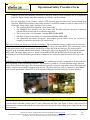
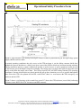
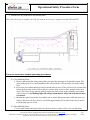
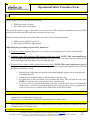
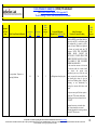
Status: PROCESSED
Saved:
Submitted: 1/23/2014 8:28:28 AM
Person: Hernandez-Garcia, Carlos ([email protected])
Org: ACCCIS
Operational Safety Procedure Review and Approval Form # 34782
(See ES&H Manual Chapter 3310 Appendix T1 Operational Safety
Procedure (OSP) and Temporary OSP Procedure for Instructions)
Click for OSP/TOSP Procedure Form
Click for LOSP Procedure Form
Type:
OSP
Serial Number:
FEL-14-34782-OSP
Issue Date:
1/27/2014
Expiration Date:
1/27/2017
Title:
FEL Gun Test Stand (GTS)
Location:
Location
Detail:
(where work is being performed)
(specifics about
Low Energy Recovery Facility (LERF) - 109A where in the
selected
location(s) the
work is being
performed)
GTS enclosure
adjacent to the
FEL vault,
GTS control
room is 217.
Risk Classification:
Without mitigation measures (3 or 4):
3
(See ES&H Manual Chapter 3210 Appendix T3 Risk Code Assignment)
With mitigation measures in place (N, 1, or 2):
1
Reason:
This document is written to mitigate hazard issues that are :
Determined to have an unmitigated Risk code of 3 or 4
Owning Organization:
FEL
Document Owner(s):
Hernandez-Garcia, Carlos ([email protected]) Primary
Supplemental Technical Validations
Gas (Dick Owen, Jennifer Williams)
Sources-Prompt Radiation & Induced Radioactivity (Keith Welch, Vashek Vylet)
Document History
Revision Reason for revision or update Serial number of superceded document
Renewing expired OSP
Comments for
reviewers/approvers:
FEL-11-002-OSP
Document was previously sent to you directly for your review. The uploaded
document incorporates your suggestions. Regarding ionizing radiation, the
document does not contain anything different from when the shielding calculations
ere done in 2007.
Attachments
Procedure: GTS OSP 2014_Rev02.pdf
THA: GTS THA 2014_Rev02.pdf
Additional Files:
Convert to PDF
Review Signatures
Subject Matter Expert : Oxygen Deficiency Hazards (ODH)->Gas
Subject Matter Expert : Radiation - Ionizing->Sources-Prompt
Radiation & Induced Radioactivity
Signed on 1/24/2014 10:04:42 AM by Dick
Owen ([email protected])
Signed on 1/24/2014 1:12:40 PM by Vashek
Vylet ([email protected])
Approval Signatures
Division Safety Officer : FEL
Org Manager : FEL
Safety Warden : Free Electron Laser (FEL) 109A
Signed on 1/27/2014 2:43:58 PM by Steve Benson
([email protected])
Signed on 1/27/2014 1:55:45 PM by George Neil
([email protected])
Signed on 1/27/2014 8:29:17 AM by Jason Delk ([email protected])
fa
Operational Safety Procedure Form
(See ES&H Manual Chapter 3310 Appendix T1
Operational Safety Procedure (OSP) and
Temporary OSP Procedure for instructions.)
DEFINE THE SCOPE OF WORK
FEL Gun Test stand (GTS)
Title:
Location:
FEL Building 18, room 217 (GTS control room) and room 109A
(GTS shielded enclosure).
Risk Classification
(per Task Hazard Analysis attached)
(See ESH&Q Manual Chapter 3210 Appendix T3 Risk Code Assignment.)
Owning Organization:
FEL
Document Owner(s):
Carlos Hernandez-Garcia
Type:
X OSP
TOSP
Highest Risk Code Before
Mitigation (3 or 4):
3
Highest Risk Code after
Mitigation (N, 1, or 2):
1
Date:
January 23, 2014
Document History (Optional)
Revision:
Serial number of superseded
document
Reason for revision or update:
Renewal and updates related to added electron gun configuration.
FEL-11-002-OSP
ANALYZE THE HAZARDS
1.
Purpose of the Procedure – Describe in detail the reason for the procedure (what is being done and why).
The purpose of this OSP is to describe in detail safe operating procedures for conducting DC photocathode gun
studies and electron beam experiments in the FEL Gun Test Stand (GTS).
2.
Scope – include all operations, people, and/or areas that the procedure will affect.
This procedure applies to the area known as the Gun Test Stand AKA GTS. The GTS is located in the
FEL Building 18. Room 217 is the control room, Room 109A is the shielded enclosure that is under room
217 and also adjacent to the FEL vault. The GTS enclosure houses three major systems:
1. A DC photocathode gun that can be either a version of the FEL gun, or a version of the CEBAF
inverted insulator gun. See description and pictures below.
2. A gas insulated (10 psi of SF6) high voltage power supply (HVPS) capable of generating up 600
kV at 5 mA DC, covered by FEL-14-33223-OSP, and
3. A mode-locked Nd:YLF drive laser with a regenerative amplifier and frequency doubler
producing 527 nm, 50 ps FWHM pulses at 200 micro-Joules and 10 Hz repetition rate, covered by
FEL-13-010-LOSP.
Systems 2 and 3 can be operated independently, regardless of the presence of an electron gun. However,
since both are interlocked to the GTS Personal Safety System, they can only be operated in conjunction
with this OSP. When the high voltage power supply is connected to the electron gun AND the a
photocathode is installed in the gun, AND the laser is aligned to illuminate the photocathode, the
For questions or comments regarding this form contact the Technical Point-of-Contact Harry Fanning
This document is controlled as an on line file. It may be printed but the print copy is not a controlled document. It is the user’s responsibility to ensure that the
document is the same revision as the current on line file. This copy was printed on 1/23/2014.
Page
1 of 22
Operational Safety Procedure Form
combined system can potentially deliver up to 600 keV beam at 10 Hz repetition rate to a diagnostics
beam line, about 2 meters long that terminates on a Faraday cup beam dump.
For safe operations of any of those systems, GTS operators must be trained on Concrete Shield Door
operation, PSS/LPSS procedures, and remote operation (via EPICS terminal located in control room 217)
of the high voltage power supply and drive laser systems.
• The concrete shield door operation is part of this OSP.
• The PSS/LPSS user manual is also part of this OSP. The Safety Systems group in coordination
with the FEL division keeps its certification up-to-date.
• The Laser system is covered under a separate FEL-13-010-LOSP.
• The High Voltage Power Supply is covered under FEL-14-33223-OSP.
• The operational procedures for the DC photocathode gun and Drive Laser are covered in a
separate document located in the GTS control room.
FEL style electron gun, Figure 1a (Cylindrical insulator): The conditioning resistor is connected to an extension
tube, 5 inches in diameter, which in turn connects to the high voltage end of the HVPS. The conditioning resistor
is then placed between the extension tube and the high voltage end of the electron gun. The electron gun is
enclosed in an Aluminum tank that bolts directly to the nipple, effectively sharing the SF6 environment with the
HVPS tank. The nipple then serves as a ‘bridge’ between the HVPS and the FEL style electron gun. In this
configuration, all of the HVSP and gun electrical components are enclosed in tanks pressurized to 10 psi with
SF6 .
CEBAF style, Figure 1 b (Inverted conical insulator): The conditioning resistor is connected to an epoxy (R30 or
R28, depending on the experiment) receptacle. The receptacle is bolted to a 20 inch OD blank flange, which in
turn is bolted down to the nipple The receptacle therefore provides electrical connection between the resistor and
a cable, and provides mechanical support to the resistor. The other end of the cable is connected to the CEBAFstyle electron gun that has either a R28 or R30 insulator holding the electrode inside the vacuum chamber.
Figure 1a) FEL style electron gun , Figure 1b) CEBAF style gun
3.
Description of the Facility – include floor plans and layout of a typical experiment or operation.
The Gun Test Stand consists of a control room (Bldg 18, room 217) and an enclosure (Bldg 18, room 109A) with
concrete shield walls that is under room 217 and is adjacent to the FEL vault. Figure 2 shows a copy of the civil
drawing of the enclosure showing the locations of the electron gun, the high voltage power supply and the drive
laser enclosure.
For questions or comments regarding this form contact the Technical Point-of-Contact Harry Fanning
This document is controlled as an on line file. It may be printed but the print copy is not a controlled document. It is the user’s responsibility to ensure that the
document is the same revision as the current on line file. This copy was printed on 1/23/2014.
Page
2 of 22
Operational Safety Procedure Form
Figure 2. GTS enclosure civil drawing showing the location of the DC photocathode gun, the high voltage power
supply (HVPS) and laser table.
In normal operating conditions, the only access to the GTS enclosure is via the sliding concrete shield door.
Behind the concrete shield door, a sliding steel door is part of the LPSS to block any laser non-ionizing radiation.
During installation periods, a metal overhead roll-up door is used for access to move equipment in and out such
as the electron gun or the High Voltage Power Supply. The roll-up door is located at the opposite end of the room
and is locked from the inside with a chain. This roll-up door IS NOT AN EXIT during nominal GTS operating
conditions. Concrete shield blocks are placed outside the roll-up door, therefore no access is possible through this
door. Since the GTS is the plenum for the FEL vault HVAC, there is a vent between the FEL emergency exit
staircase and the GTS.
Figure 3 shows a civil drawing of the second floor (room 217) above the GTS enclosure (room 109A) indicating
locations for the HVPS 208 VAC disconnect and PSS contactor.
For questions or comments regarding this form contact the Technical Point-of-Contact Harry Fanning
This document is controlled as an on line file. It may be printed but the print copy is not a controlled document. It is the user’s responsibility to ensure that the
document is the same revision as the current on line file. This copy was printed on 1/23/2014.
Page
3 of 22
Operational Safety Procedure Form
Figure 2. Civil drawing of the GTS second floor, room 217.
4.
Authority and Responsibility:
4.1
Who has authority to implement/terminate
George Neil.
4.2
Who is responsible for key tasks
Carlos Hernandez-Garcia is responsible for training GTS operators, for ensuring safe operation of
the Gun Test Stand (GTS) and for leading the R&D program. Approved GTS operators will be
added to a list of the Approved/Trained individuals sheet to be posted at the entrance of the GTS
enclosure Room 109A, and by the high voltage power supply disconnect in the GTS control room
217.
4.3
Who analyzes the special or unusual hazards (See ES&H Manual Chapter 3210 Appendix T1 Work Planning, Control,
and Authorization Procedure)
Ionizing Radiation - V. Vylet
Oxygen Deficiency Hazards – Dick Owen
FEL Safety Officer – Steve Benson.
GTS Enclosure Sweep Procedures – Henry Robertson.
4.4
What are the Training Requirements (See http://www.jlab.org/div_dept/train/poc.pdf)
•
•
•
•
SAF100 ES&H Orientation
SAF103 Oxygen Deficiency Hazard
SAF104 Lock, Tag and Try
SAF143kd FEL Safety awareness
For questions or comments regarding this form contact the Technical Point-of-Contact Harry Fanning
This document is controlled as an on line file. It may be printed but the print copy is not a controlled document. It is the user’s responsibility to ensure that the
document is the same revision as the current on line file. This copy was printed on 1/23/2014.
Page
4 of 22
Operational Safety Procedure Form
•
5.
This document
Personal and Environmental Hazard Controls Including:
5.1
Shielding
The prompt ionizing radiation hazard is due to x-ray emission caused by electrons impinging on a
material, typically vacuum chambers and beam lines. The maximum voltage in the power supply is 600
kV and although the current will be limited to a maximum of 100 micro-Amperes, in the worst case
scenario the field emission current could potentially reach 5 mA DC, the physical limit of the HVPS. At
this current and voltage, the potential dose rate at the staircase vent is approximately 5 R/hr (see
calculations below). This is above the 1 R/hr level at which engineered controls must be implemented.
SHIELDING CALCULATIONS by Vashek Vylet
Radiation dose rates around the GTS were estimated assuming a simple point source geometry and using Xray production source terms for 600 keV electrons from NCRP Report no. 51. The gun, the associated SF6
tank and vacuum pipe present a complex geometry. Our estimates are based on a simple assumption that
any exiting X-ray encounters 0.5” of steel, which is likely very conservative for a range of directions and
angles through the vessel walls and/or flanges (see Figure 1). Calculations were done for a number of
locations, only those with the highest dose rates are reported here: a) outside door leading to the entrance
maze to FEL, and b) exit point of the cable penetration on the 2nd floor, above the GTS enclosure. Dose
rates are highest at the point a) because it is in direct view from the source through a ventilation opening in
the concrete wall of the entrance maze. In these estimates both normal operation and accident scenarios
were considered.
Normal Operation: 600 kV, Iav = 10 nA (1 nC/pulse @ 10 Hz)
The highest dose rates in this regime are 2-3 orders of magnitude lower than natural background .
Maximum Credible Accident: Laser operates in CW mode, leading to Iav = 5 mA and deterioration of
vacuum. It is likely that this condition would be terminated within 10 seconds by a vacuum sensor.
However, if the latter fails, a SF6 leak would likely develop within 1 – 2 minutes due to damage caused by
the HV arc. Due to the uncertainty of the source term, we estimate that the total dose accumulated over 2
minutes could be somewhere in the range of 41 – 160 mrem at the maze and 2.3 to 9.2 mrem at the cable
penetration. These values do not exceed the current limits for accident scenarios specified in the ESH
Manual (6310-T2: Prompt Radiation Control Policy) as “less than 15 rem in any one hour”.
Summary: Current shielding (as of December 2007) of the GTS is satisfactory and compliant with
applicable JLab policies.
Note: All the shielding is the same as when first installed in Dec 2007 and verified in Jan 2014.
5.2
Interlocks
The Safety Systems Group has written a complete Personal Safety System User Guide (Revision 1.0
January 10 2008) that is part of this OSP. Important PSS information and related sweep procedures
taken from that document follow.
The FEL-GTS personnel safety system is an engineered interlock system to help protect personnel from
exposure to prompt ionizing radiation (PIR) that results from operation of the electron gun in the GTS. The
For questions or comments regarding this form contact the Technical Point-of-Contact Harry Fanning
This document is controlled as an on line file. It may be printed but the print copy is not a controlled document. It is the user’s responsibility to ensure that the
document is the same revision as the current on line file. This copy was printed on 1/23/2014.
Page
5 of 22
Operational Safety Procedure Form
GTS is composed of a completely enclosed concrete enclosure Room 109A (AKA GTS enclosure) and a
control room outside the test cave on its mezzanine Room 217. There are two personnel doors, a moving
concrete slab and a sliding steel plate. It is through these doors that personnel enter and exit the GTS during
a sweep. A rollup over-head door is only used for loading large pieces of equipment. This door is
interlocked and is blocked by concrete shielding during operations.
There are presently two high voltage power supply (HVPS) sources. The Gun 600kVDC, 5mA Power
Supply and the Drive Laser Power Supply.
The Personnel Safety System must be able to ensure that a HVPS is only allowed to operate when safe to
do so. It is the job of the PSS logic to determine the status of the test cave and, if a fault is detected, all
HVPS sources are shut off.
An interlock between the nitrogen source and the air-handling unit has been installed and is
operational as an engineered control. The interlock is a fail-closed solenoid valve up-stream of the
nitrogen manifold and mounted outside of the GTS enclosure that closes when the air handing unit
is not working.
5.3
Monitoring systems
The GTS enclosure has one Radiation Alarming Monitor (CARM) connected to the FEL radiation
monitoring system to alert personnel working in the GTS enclosure in the event of FEL electron beam loss
(one gamma probe is located behind the laser table attached to the air vent, one neutron probe is located
also inside the GTS to one side of the laser table in the upper-left corner).
The GTS enclosure has its own CARM radiation monitoring system consisting of one gamma probe located
next to the concrete shield door controls outside the enclosure, one more gamma probe is located in the
FEL exit staircase and the last of three gamma probes is located in the GTS control room 217 on top of the
PSS rack.
ODH sensors are inside the GTS enclosure, in the rear stair well, and at collection points in the FEL vault.
The Safety System Group electronics continuously monitor the ODH sensor.
5.4
Ventilation
The GTS enclosure is part of the air conditioning system of the FEL vault. When the air conditioning
system is operational, any SF6 spill or leak off the high voltage power supply would be quickly dispersed
due to the high flow rate of the air conditioning system. When the air conditioning system is off, any SF6
would drain out of the GTS vault through the air conditioning recovery port and into the rear stair well of
the FEL vault and then into the FEL vault.
The GTS enclosure is designed as an ODH 0 area.
The ODH assessment is addressed under a separate document JLAB-TN-07-082 and also in the high
voltage power supply FEL-14-33223-OSP. The floor area of room 109A was measured as 606.5 square
feet with a 10-foot ceiling (6065 cubic feet). At one end of the room is an intake duct to the air-handling
For questions or comments regarding this form contact the Technical Point-of-Contact Harry Fanning
This document is controlled as an on line file. It may be printed but the print copy is not a controlled document. It is the user’s responsibility to ensure that the
document is the same revision as the current on line file. This copy was printed on 1/23/2014.
Page
6 of 22
Operational Safety Procedure Form
unit that supplies heated or cooled air mixed with fresh air to the FEL accelerator room. At the other end of
the room is a hole in the wall that is open to the accelerator room and is covered with steel screen.
Therefore, the GTS enclosure room 109A is considered a plenum. There is one roll up door, normally
closed, and a concrete door, normally open. The concrete doorway has plastic panels to eliminate airflow
through the doorway. In accordance with Appendix 6500-T3, reliable ventilation may be considered a
relevant factor in this ODH assessment if the volume of air in the room is replaced with fresh air at a
minimum of once an hour. The ventilation for this room comes from an air-handling unit. This unit
operates 24 hours a day and 7 days a week. Because this room is a plenum, the air changes are larger than
50 air changes an hour.
5.5
Other (Electrical, ODH, Trip, Ladder) (Attach related Temporary Work Permits or Safety Reviews as appropriate.)
The following hazards are detailed in attached Task Hazard Analysis.
• ODH
• Exposure to ionizing radiation
• Exposure to non-ionizing radiation
• Potential to crushing of limbs by operation of the concrete shield door.
• Potential to tripping off while stepping over the concrete shield door trench.
6.
List of Safety Equipment:
6.1
List of Safety Equipment:
Personal Protective Equipment (PPE) is required when making the system safe. The system is made safe
by powering off the high voltage power supply disconnect (located in GTS control room 217), and
following Lock-Tag & Try procedures to apply hasp and personal labels to the high voltage power supply
disconnect. PPE includes:
1. Non-melting/untreated natural fiber long pants and long sleeved shirt or jacket
2. Safety glasses.
3. Hearing protection.
The listed PPE has been accepted by Todd Kujawa as meeting the newest edition (2012) of NFPA 70E.
Additionally, in the GTS control room 217, laser safety goggles are located next to the PSS/LPSS console.
Inside the GTS enclosure, the PPE box contains leather gloves and safety glasses.
6.2
Special Tools:
Ground Sticks are provided inside the GTS enclosure near the high voltage power supply tank.
Ground sticks are required when:
• Accessing the inverted insulator in the Gun, or the high voltage cable receptacle on the high
voltage power supply side is required, or
• Access to the FEL style electron gun is required for photocathode work.
Lock-Tag & Try personal lock(s), labels and a hasp to be used in the HVPS disconnect are located
inside a toolbox just below the HVPS disconnect.
For questions or comments regarding this form contact the Technical Point-of-Contact Harry Fanning
This document is controlled as an on line file. It may be printed but the print copy is not a controlled document. It is the user’s responsibility to ensure that the
document is the same revision as the current on line file. This copy was printed on 1/23/2014.
Page
7 of 22
Operational Safety Procedure Form
DEVELOP THE PROCEDURE
1.
Associated Administrative Controls
The configuration of the gun and laser systems is highly dependent on administrative procedures and
configuration control. There are several assumptions concerning HVPS system configuration that form part of
this logic.
•
Safety Systems Group staff will be responsible for:
o LPSS engineered controls
o PSS administrative and engineered controls
•
FEL staff will be responsible for:
o LPSS administrative controls
o SF6 administrative and engineered controls
*Administrative controls includes: Authority/responsibility, Procedures, Postings, and PPE
•
•
•
•
•
•
•
•
•
2.
FEL GTS personnel are responsible for safe operation of the GTS facility. This includes limiting beam
power to fall within the identified operations and safety parameters.
FEL vault PSS logic manages the FEL exit labyrinth door switches and Run/Safe Box 204 to provide an
“Area Secure” signal to the GTS logic
The GTS enclosure is currently rated ODH 0
o Since SF6 is heavier than air, one active ODH sensor is installed under the HVPS tank and will set
the off the alarm in the event of SF6 leakage
FEL staff provides the following to the PSS/LPSS:
o Gun HVPS interface
o Laser HVPS interface
o Laser shutter interface
The PSS shall provide “Run” mode status to FEL owned Gun HVPS control chassis
The Radiation Control Group provides CARMs/probes as needed
Fixed and removable shielding - i.e. concrete and steel walls, doors, vents and blocks - are adequate to
meet all safety requirements that are not protected by functions of the PSS or LPSS.
FEL / Facilities Management staff provides a door/gate to secure the exit labyrinth area
The Laser HVPS does not provide its operational status (e.g. OFF/SAFE) to the LPSS
Operating Guidelines
For questions or comments regarding this form contact the Technical Point-of-Contact Harry Fanning
This document is controlled as an on line file. It may be printed but the print copy is not a controlled document. It is the user’s responsibility to ensure that the
document is the same revision as the current on line file. This copy was printed on 1/23/2014.
Page
8 of 22
Operational Safety Procedure Form
Staffing
When the GTS is in sweep mode or higher, there must be a cognizant1 person in the FEL building responsible for
GTS PSS operation. That is, someone who is aware of, and responsible for safe operation of the GTS; typically
the personnel conducting gun and/or beam studies.
GTS shift change over
At the end of a shift, the Principle Investigator or designee must either return the GTS to Open Access, or
formally turn over oversight duties to another GTS qualified operator. The incoming GTS qualified operator
must sign in the PSS logbook, indicating that they are now responsible for GTS PSS operations.
The outgoing GTS qualified operator should brief the incoming GTS operations staff on the following items:
PSS/LPSS Status
PSS/LPSS faults or alarms during shift
PSS/LPSS Logbook
All PSS operations and changes of state shall be recorded in the PSS logbook, located on the PSS console in the
GTS control room. This log is a legal record of PSS operation.
GTS Operation
Operation of the GTS includes use of a Personnel Safety System (PSS) and a Laser Personnel Safety System
(LPSS). These involve using the proper door configuration, sweep and mode procedures, and securing of the
GTS test cave and FEL Exit Labyrinth area described below in this document.
GTS Operator Requirements
Additionally to the training listed in section 4.4, the GTS operator must:
1. Read and understand this OSP that includes PSS sweep procedures and .
2. Receive the practical training on this OSP and on Gun operational procedures from system owner (Carlos
Hernandez-Garcia) or designee
3. Perform walkthrough of the following areas: GTS control room, mezzanine, spiral staircase, and
enclosure
3.
Notification of Affected Personnel (who, how, and when)
Safety: FEL Safety Warden, Jason Delk 269-5609
Safety: FEL Division Safety Officer, Steve Benson, 269-5029
GTS system owner: Carlos Hernandez-Garcia, 269-6862, cel. 757-303-1038
ODH, Fire: CEBAF Crew Chief: 269-7045, cel. 757-630-7050.
Emergency: Guard gate 269-5822
1
Cognizant is defined as a person or persons trained in the operation and operational hazards of the FEL-GTS and associated
systems, including the Personnel Safety System/Laser Personnel Safety System.
For questions or comments regarding this form contact the Technical Point-of-Contact Harry Fanning
This document is controlled as an on line file. It may be printed but the print copy is not a controlled document. It is the user’s responsibility to ensure that the
document is the same revision as the current on line file. This copy was printed on 1/23/2014.
Page
9 of 22
Operational Safety Procedure Form
4.
List the Steps Required to Execute the Procedure: from start to finish.
The GTS enclosure can operate in two modes: a) Laser Alignment and b) Run mode. Laser Alignment mode is
utilized for laser work only and no high voltage operations are permitted by LPSS/PSS. The enclosure is shielded
from non-ionizing laser radiation to the outside by a sliding steel door interlocked to the LPSS/PSS. In case of
emergency, this door can be manually slide open form the inside or outside. If the door is opened while in Laser
Alignment mode permit, it will crash the LPSS and therefore close laser shutters and cut power to the laser.
In Run mode, the PSS gives “Gun Permit” which allows high voltage operations and Laser operations. A sliding
concrete shield door in front of the steel sliding door shield the enclosure from prompt ionizing radiation during
high voltage operations. Procedures to operate the sliding concrete shield door are described at the end of this
section.
The PSS/LPSS console is located in the GTS control room. The figure below shows a sketch of the console.
SSI Status
The Safety System Interface (SSI) status lamps display the active permits to the Gun, Drive Laser, and future RF
systems.
"Gun Permit" will light when the gun HVPS has a PSS permit.
"Laser Permit" will light when the Drive Laser has PSS & LPSS HVPS permits and Shutter permit.
For questions or comments regarding this form contact the Technical Point-of-Contact Harry Fanning
This document is controlled as an on line file. It may be printed but the print copy is not a controlled document. It is the user’s responsibility to ensure that the
document is the same revision as the current on line file. This copy was printed on 1/23/2014.
Page
10 of 22
Operational Safety Procedure Form
Door Status
The Door Status lamps are used to indicate the important positions of the doors.
The moveable concrete door is the standard personnel door.
Note: this door will automatically open when any PSS/LPSS crash switch is pushed.
The sliding steel door is used to control light emitting from the cave during Laser Alignment mode.
Note: This door must also be closed during and after a PSS sweep.
The roll-up door is only used to install large pieces of equipment.
Keyswitch Controls
The keyswitch controls are used to change the state of the PSS and LPSS operating modes and reset non-access
control faults.
The colored LEDs indicate the status of the PSS operating mode. For the PSS there are two keyswitches and one
key used in the operation of the GTS. The left hand keyswitch is used to switch between OPEN mode and
SWEEP mode. The key can only be removed when in the “Sweep” position. The same key is used for the sweep
so that the GTS cannot be accidentally switched to RUN while a sweep team is in the test cave. When a sweep is
completed the key is returned to the right hand key switch and used to set the operating mode to RUN.
If a non-access control fault occurs, such as a radiation monitor trip, the key must be cycled from RUN to
SWEEP then back to RUN in order to reset the PSS system.
Note: Switching the keyswitch from Sweep to RUN starts a timer. The gun HVPS and Laser shutters may not be
operated until the timer has reached 30 seconds.
For LPSS Laser Alignment there are two keyswitches with a shared key. The keyswitch on the panel is used to
switch between RUN mode and ALIGNMENT mode. The key can only be removed when in the “Alignment”
position. The same key is used in the Laser permit status box in the cave so that the GTS cannot be accidentally
switched to RUN while laser qualified staff are performing tests. The keyswitch in the cave is used to switch the
shutter permits to ALIGNMENT mode. When testing is complete, the key is returned to the control room panel
keyswitch and used to set the operating mode to RUN.
Note: Switching the cave keyswitch to ALIGNMENT starts a timer. The Laser shutters will not operate until the
timer has reached 30 seconds.
Safety Crash
The Safety Crash is used to shutdown all GTS systems in an emergency.
This crash switch will remove permits to all high voltage power sources and the laser shutters. It will also crash
the sweep and force the concrete door to open.
Door Configurations
Gun Operations
In this mode, the moving concrete door, the sliding steel door, and the roll-up door must be closed completely.
Laser Alignment Operations
For questions or comments regarding this form contact the Technical Point-of-Contact Harry Fanning
This document is controlled as an on line file. It may be printed but the print copy is not a controlled document. It is the user’s responsibility to ensure that the
document is the same revision as the current on line file. This copy was printed on 1/23/2014.
Page
11 of 22
Operational Safety Procedure Form
In this mode the moving concrete door must be fully open, the sliding steel door and the roll-up door must be
closed completely.
PSS Operational Modes
Pre-operational Checks:
In order to avoid having to re-sweep, the following preoperational checks should be made:
• Confirm that the FEL Exit Labyrinth is secure.
• Door operation
o Check that the roll-up door is closed
o Check that there are no obstacles blocking the moving concrete and sliding steel doors
Open Mode
Open mode is the default state for the PSS. In this mode all Run/Safe boxes are not armed and the gun HVPS
and laser shutter permits are OFF. This mode can be reached by turning the sweep keyswitch to OPEN or by
pushing any PSS/LPSS crash switch.
Conditions:
– No Gun HVPS permitted
– Laser Power Supply permitted when Class 1 enclosure is secure
– Roll-up door may be open
– FEL vault can be in any state
Note: Moving concrete door must be fully open to meet other life safety requirements
• Sweep Mode
Prior to beginning operations in the GTS, the beam enclosure and the FEL Exit Labyrinth must be secure. Both
areas must be searched by 2 qualified personnel.
Note: See Section 8.0 of this user's guide for instructions that describe the proper sweep procedures and
patterns.
Conditions:
–
–
–
–
–
No Gun HVPS permitted
Laser Power Supply permitted when Class 1 enclosure is secure
Roll-up door must be closed
Sliding steel door must be fully closed when sweep complete
Moving concrete door must be fully closed when sweep complete
• Ready Mode
“Ready Mode” is an internal PSS mode. It serves as a mode that the PSS will drop to when there is a non-access
control fault, such as a radiation monitor.
For questions or comments regarding this form contact the Technical Point-of-Contact Harry Fanning
This document is controlled as an on line file. It may be printed but the print copy is not a controlled document. It is the user’s responsibility to ensure that the
document is the same revision as the current on line file. This copy was printed on 1/23/2014.
Page
12 of 22
Operational Safety Procedure Form
• Run Mode
In order to enter and remain in RUN mode, all PSS interlocks must be OK.
Conditions:
– Area must be swept and secured
– Gun HVPS permitted (30 second delay)
– Laser Power Supply permitted
– Moving concrete door closed
– Sliding steel door closed
– Roll-up door closed
– Crash buttons active
– Audible warnings (for 30 seconds)
– Visible warnings (continuous)
– PSS shutters open (30 second delay)
– CARMs active
– Sweep Key in RUN position
– Laser Alignment Key in RUN position (Run Mode excludes Laser Alignment mode)
– FEL exit labyrinth area must be secure
Note: If a CARM trips the PSS, turn the key from RUN back to Sweep, then back to RUN in order to reset the
fault.
What happens if someone is in the test cave when it is switched to RUN Mode?
• In all areas the Run/Safe box lamps switch to “Unsafe”
•
An alarm klaxon sounds for 30 seconds before the gun is enabled.
•
Personnel should immediately exit the tunnel, hitting the nearest crash switch on the way out.
If someone is present in the cave after a sweep is complete, it may be a DOE reportable incident. All operations
must cease at once and assistance given to any injured personnel, if required. The Principle Investigator must
write down the names of all personnel on shift and that of the person(s) that were in the cave. The Principle
Investigator must then contact the accelerator division safety officer and the radiation control group leader for
further instructions.
• Returning to Open Mode
•
•
•
•
Turn off the gun HVPS
Switch the cave to “Sweep” mode
Remove key and insert in left hand key switch
Switch the cave to “OPEN” mode
For questions or comments regarding this form contact the Technical Point-of-Contact Harry Fanning
This document is controlled as an on line file. It may be printed but the print copy is not a controlled document. It is the user’s responsibility to ensure that the
document is the same revision as the current on line file. This copy was printed on 1/23/2014.
Page
13 of 22
Operational Safety Procedure Form
• LPSS Operational Modes
Pre-operational Checks:
• The FEL Exit Labyrinth may be open.
• Door operation
o Check that the roll-up door is closed
o Check that there are no obstacles blocking the sliding steel door
o Moving concrete door must be fully open to meet life safety requirements
• Open Mode
Open mode is the default state for the LPSS. This mode can be reached by turning the PSS sweep keyswitch to
OPEN or by pushing any PSS/LPSS crash switch.
Conditions:
– No Gun HVPS permitted
– Laser Power Supply permitted when Class 1 enclosure is secure
– Roll-up door may be open
– FEL vault can be in any state
• Laser Alignment Mode
In order to enter and remain in Laser Alignment mode, all LPSS interlocks must be OK
Conditions:
– PSS Keyswitch is in the “OPEN” position
– No Gun HVPS permitted
– Laser Power Supply permitted
– Class 4 laser operations permitted with proper LPE
– Moving block must be fully open
– Roll-up door must be closed
– Sliding door must be closed
– PSS shutters open (30 sec. delay)
– Audible warnings (for 30 seconds)
– Visible warnings (continuous)
– Crash buttons active
– Administrative “sweep” of room
– Laser Alignment Keyswitch set (Laser Alignment Mode excludes Run mode)
• Returning to Open Mode
•
•
•
•
If open, close the covers of the laser hutch
Turn the Laser keyswitch in the cave counter-clockwise and remove
Open the sliding steel door
Return to the control room
For questions or comments regarding this form contact the Technical Point-of-Contact Harry Fanning
This document is controlled as an on line file. It may be printed but the print copy is not a controlled document. It is the user’s responsibility to ensure that the
document is the same revision as the current on line file. This copy was printed on 1/23/2014.
Page
14 of 22
Operational Safety Procedure Form
•
Insert the Laser keyswitch and turn clockwise to “RUN” mode to allow for gun operations
Sweep Procedures
General Duties of the Sweep Team
The sweepers should ensure that all of the appropriate doors are closed. Confirm that the PSS panel or screens
indicates that the doors are closed and the PSS panel LEDs read “Sweep Mode” for both system A and B.
It is the duty of the sweep team to thoroughly search an area for personnel. During the sweep, the team members
must assume that there may be personnel who did not hear announcements or are incapacitated.
The sweepers should not perform any other tasks when doing a tunnel sweep. Once the sweep starts, a 2 minute
timer also starts. If the sweep is not completed within 2 minutes, the sweep will drop and will have to be reswept.
At least one of the sweepers shall be a qualified lead sweeper. This is someone who is familiar with the sweep
procedures for the GTS and FEL, and has swept the area at least once.
If anyone is found in the enclosure during a sweep, the person(s) must accompany the sweep team back to the
GTS control room. The lead sweeper or the principle investigator shall record the names of the personnel found
during the sweep in the PSS logbook. The Principle Investigator shall then inform the Safety Systems Group
Leader within one business day.
GTS Sweep Procedure for Gun Operations
Identify two qualified personnel as the sweep team.
Walk through the test cave
• Ask any personnel in the cave to leave immediately
• Confirm that the roll-up door is closed
• Confirm that the concrete door is fully open
Return to the control room
• Look at the PSS panel.
o Verify that the doors indicates their proper positions
o Verify that the all system permits are OFF
o Verify that the FEL Exit Area lamp is ON
•
Switch the PSS left hand keyswitch to Sweep mode and remove the sweep key
o Verify that the PSS changes to Sweep mode
o Take a copy of the sweep map if desired
For questions or comments regarding this form contact the Technical Point-of-Contact Harry Fanning
This document is controlled as an on line file. It may be printed but the print copy is not a controlled document. It is the user’s responsibility to ensure that the
document is the same revision as the current on line file. This copy was printed on 1/23/2014.
Page
15 of 22
Operational Safety Procedure Form
Two sweepers exit the control room area. One is posted at the entrance of the test cave while the other enters
through the concrete door.
•
•
•
•
•
•
•
Close the sliding steel door
Arm the first Run/Safe box (RS02) on the west wall
o Verify that the Yellow “Operational” indicator is lit
Arm the second Run/Safe box on the east wall
o Verify that the Yellow “Operational” indicator is lit
Exit the test cave closing the sliding steel door
Close the moving concrete door. It must close within 60 seconds in order to maintain the sweep
Return to the control room
Place the sweep key in the right hand keyswitch and switch it to “Run” mode to begin operations
Note: Once the sweep is complete, the sweepers have exited the test cave and closed the concrete door,, the PSS
will automatically go to “Ready” mode.
For questions or comments regarding this form contact the Technical Point-of-Contact Harry Fanning
This document is controlled as an on line file. It may be printed but the print copy is not a controlled document. It is the user’s responsibility to ensure that the
document is the same revision as the current on line file. This copy was printed on 1/23/2014.
Page
16 of 22
Operational Safety Procedure Form
GTS Sweep Procedure for Laser Alignment
Note: The detailed Sweep requirements for Laser Alignment mode are explained in the GTS LSOP.
FEL exit labyrinth area may be secured prior to start of GTS cave sweep.
Walk through the test cave
• Ask any personnel in the cave to leave immediately
• Confirm that the roll-up door is closed
• Confirm that the concrete door is fully open
Return to the control room
• Look at the PSS panel.
o Verify that the doors indicates their proper positions
o Verify that the all system permits are OFF
•
Switch the Laser keyswitch to Alignment mode and remove the key
The sweeper exits the control room area and enters the cave through the concrete door
•
•
•
•
Close the sliding steel door
Check for any remaining personnel
Use appropriate LPE
Insert the key into Laser permit status box in the cave and turn it clockwise to the “Alignment” position to
begin tests
o The Laser warning horn on the Laser permit status box in the cave will sound for 30 seconds
o Once the 30 second timer is complete, the LPSS will provide a "Shutter Permit"
o The yellow strobe outside the door will start flash
o The yellow lamp on the Laser permit status box in the cave will light
o The LPSS will automatically open the laser shutters
For questions or comments regarding this form contact the Technical Point-of-Contact Harry Fanning
This document is controlled as an on line file. It may be printed but the print copy is not a controlled document. It is the user’s responsibility to ensure that the
document is the same revision as the current on line file. This copy was printed on 1/23/2014.
Page
17 of 22
Operational Safety Procedure Form
FEL-Exit Labyrinth Area Sweep Procedure
FEL exit labyrinth area must be secured prior to switching the GTS PSS to “RUN” mode.
Identify two qualified personnel as the sweep team.
Go to the MCC and request/access the special sweep key from the Keywatcher panel
Look at the FEL screen on the PSS computer.
o Verify that the exit area doors are closed
Two sweepers enter the FEL vault. One is posted at the entrance of the exit labyrinth while the other enters
through the wire door.
•
•
•
•
•
•
•
Close the wire door
Go to the fire door and confirm that it is completely closed and locked
Arm the Run/Safe box (RS204) on the south wall
o Verify that the Yellow “Operational” indicator is lit
Exit the area closing the wire door completely
Check that the "Area Secure" light on the wall outside of the door is lit
For questions or comments regarding this form contact the Technical Point-of-Contact Harry Fanning
This document is controlled as an on line file. It may be printed but the print copy is not a controlled document. It is the user’s responsibility to ensure that the
document is the same revision as the current on line file. This copy was printed on 1/23/2014.
Page
18 of 22
Operational Safety Procedure Form
•
Return to the key to the MCC Keywatcher panel
Note: Once the sweep is complete, the PSS will send an "area secure" signal to both the FEL and GTS.
Concrete shield door normal operating procedures:
To Close Shielding Door: a. Remove the trench plate using plate-pulling tool provided and store in designated location. The
plate-pulling plate is on a hook attached to the wall inside the GTS enclosure next to the sliding
door.
b. Press door close button and keep it held in for the door to move. There will be a few seconds delay
before the door starts to move due to the pre-set time delay switch to allow pump to come up to
speed. The door will stop moving when it reaches the limit switch, at this point the close button
can be released. A red flashing light with a high volume buzzer will go off each time the door
is actuated.
c. Monitor the space between the door and the jam to ensure that no one enters while the door is in
motion. The door will move slowly, it will take approximately 45 seconds for the door to travel
from the fully open to closed.
To Open Shielding Door: a. Press open button and keep it hold in for the door to move, there will be a few seconds delay
For questions or comments regarding this form contact the Technical Point-of-Contact Harry Fanning
This document is controlled as an on line file. It may be printed but the print copy is not a controlled document. It is the user’s responsibility to ensure that the
document is the same revision as the current on line file. This copy was printed on 1/23/2014.
Page
19 of 22
Operational Safety Procedure Form
before the door starts to move due to the pre-set time delay switch to allow pump to come up to
speed. The door will stop moving when it reaches the limit switch, at this point the open button
can be released. A red flashing light with a high volume buzzer will go off each time the door
is actuated.
b. Once to door is fully open, set the trench cover plate in the trench to prevent tripping.
Note: - The control buttons must be kept depressed to move the door. When the door reaches the open or
close limit switches, it will stop moving and the button can be released. It is necessary for the door to reach
the limit switch in open or close position to activate the PSS interlocks.
5.
Back Out Procedure(s) i.e. steps necessary to restore the equipment/area to a safe level.
At any time during GTS operations, the PSS can be brought to OPEN or safe mode, in case there is a need
for accessing the enclosure or to conclude high voltage operations.
Returning the PSS to Open Mode
•
•
•
•
•
Turn off the gun HVPS from the EPICS control screen
Proceed to the PSS console and switch the key to “Sweep” mode
Remove key and insert in left hand key switch
Switch the key to “OPEN” mode
Proceed to the GTS enclosure entrance and open the sliding concrete shield door following procedure
described in step 4 List of steps required to execute the procedure.
At any moment the PSS Safety Crash buttons can be depressed. This action will cut off the gun high
voltage power supply and will close the laser shutter if those systems are operational. It will also crash the
sweep and will force open the sliding concrete shield door.
Since ionizing radiation is present in the enclosure only when the gun is at high voltage, depressing any of
the PSS Safety Crash buttons will restore the area to a safe level.
6.
Special environmental control requirements:
6.1 Environmental impacts (See EMP-04 Project/Activity/Experiment Environmental Review)
SF6 gas is used as an electrical insulating gas inside the pressurized (10 psi) high voltage power
supply and gun tanks. SF6 is a green house gas that must be re-used to avoid releasing it into the
atmosphere when there is a need to open the tanks, i.e. gun or high voltage power supply
maintenance. See High Voltage Power Supply FEL-14-33223-OSP for details on gas transferring
operations.
SF6 is a powerful green house gas, 23,900 times worse than CO2.
6.2 Abatement steps (secondary containment or special packaging requirements)
To prevent the escape of this gas we have installed a SF6 recovery system. This system passes the
gas back and forth between a flexible storage bag, located outside, and the electron gun & high
voltage power supply. The system is also equipped with a vacuum pump to ensure near complete
SF6 gas recovery. See high voltage power supply FEL-14-33223-OSP for details on gas transferring
operations.
For questions or comments regarding this form contact the Technical Point-of-Contact Harry Fanning
This document is controlled as an on line file. It may be printed but the print copy is not a controlled document. It is the user’s responsibility to ensure that the
document is the same revision as the current on line file. This copy was printed on 1/23/2014.
Page
20 of 22
Operational Safety Procedure Form
7.
Unusual/Emergency Procedures (e.g., loss of power, spills, fire, etc.)
The following is a list of currently installed alarms:
1. ODH (blue strobe + buzzer)
2. Fire (white strobe + high pitch)
The expected response to any of the alarms is to evacuate the GTS enclosure immediately, proceed to FEL
muster point located at the FEL front door, and notify the crew chief.
Return to normal operations occurs when alarms are cleared by the following personnel:
1. ODH cleared by MCC Crew Chief
2. Fire cleared by Facilities Management
Other emergency procedures not covered by alarms are:
a) Ventilation failure. Expected Response is to evacuate area immediately and convene at muster point.
b) Personnel inside GTS enclosure AND concrete shield door closed. NOTE: This event should never
occur if proper sweep procedures are followed. Expected response is to proceed to the concrete shield
door exit and press the crash button. This will open the door.
c) Electrical Power failure AND concrete shield door closed. NOTE: This event should never occur if
proper sweep procedures are followed. In case of power failure and personnel trapped inside GTS with
the concrete shield door closed:
1. Proceed to the sliding door and open the two manual hydraulic by-pass valves located on the
wall behind the ram.
2. Attach the lever chain hoist hook to the pull point on the door edge.
3. Set chain hoist to lift and operate lever to tighten the chain. This will pull the door open.
NOTE: It should not take a great deal of force to open the door.
4. If excessive force is required on the chain hoist lever: a) Set the hoist to lower, b) Release the
chain tension, c) Check to ensure the manual by-pass valves are open, d) Re-try opening door.
If still excessive force is needed call the Guard Gate at 269-5822 for help.
8.
Instrument Calibration Requirements (e.g., safety system/device recertification, RF probe calibration)
ODH heads are maintained and continuously monitored by the Safety Systems Group. CARMS are
maintained by the Radiation Control group.
Both groups are responsible for calibrations and maintenance of their systems.
9.
Inspection Schedules
PSS certifications are performed every six months by the Safety Systems Group in coordination with FEL
personnel and/or GTS system owner.
10. References/Associated Documentation
For questions or comments regarding this form contact the Technical Point-of-Contact Harry Fanning
This document is controlled as an on line file. It may be printed but the print copy is not a controlled document. It is the user’s responsibility to ensure that the
document is the same revision as the current on line file. This copy was printed on 1/23/2014.
Page
21 of 22
Operational Safety Procedure Form
•
•
•
•
•
Laser FEL-13-010-LOSP
High Voltage Power Supply FEL-14-33223-OSP
PSS/LPSS User guide Revision 1.0 January 10, 2008
ODH Assessment JLAB-TN-07-082
DC electron gun operational procedures
11. List of Records Generated (Include Location / Review and Approved procedure)
Distribution: Copies to: affected area, authors, Division Safety Officer
Expiration: Forward to ESH&Q Document Control
Form Revision Summary
Revision 1.3 – 11/27/13 – Added “Owning Organization” to more accurately reflect laboratory operations.
Revision 1.2 – 09/15/12 – Update form to conform to electronic review.
Revision 1.1 – 04/03/12 – Risk Code 0 switched to N to be consistent with 3210 T3 Risk Code Assignment.
Revision 1.0 – 12/01/11 – Added reasoning for OSP to aid in appropriate review determination.
Revision 0 – 10/05/09 – Updated to reflect current laboratory operations
ISSUING AUTHORITY
FORM TECHNICAL POINT-OF-CONTACT
APPROVAL DATE
REVIEW REQUIRED DATE
REV.
ESH&Q Division
Harry Fanning
12/01/11
12/01/14
1.3
This document is controlled as an on line file. It may be printed but the print copy is not a controlled document. It is the user’s responsibility to ensure that the
document is the same revision as the current on line file. This copy was printed on 1/23/2014.
For questions or comments regarding this form contact the Technical Point-of-Contact Harry Fanning
This document is controlled as an on line file. It may be printed but the print copy is not a controlled document. It is the user’s responsibility to ensure that the
document is the same revision as the current on line file. This copy was printed on 1/23/2014.
Page
22 of 22
Task Hazard Analysis (THA) Worksheet
Click
For
Word
Doc
(See ES&H Manual Chapter 3210 Appendix T1
Work Planning, Control, and Authorization Procedure)
Author:
Carlos Hernandez-Garcia
Date:
Task #:
January 23, 2014
If applicable
Complete all information. Use as many sheets as necessary
Task Title:
FEL Gun Test Stand (GTS) operations
Division:
FEL
Lead Worker:
Task Location:
Department:
FEL building 18, GTS enclosure room 109A and room 217
Frequency of use:
As needed
Carlos Hernandez-Garcia
Ionizing Radiation Engineered Controls
The prompt ionizing radiation hazard is due to x-ray emission caused by electrons impinging on material. The maximum
voltage in the power supply is 600 kV and although the current will be limited to a maximum of 100 microamperes,
in the worst case scenario the field emission current could potentially reach 5 mA DC, the physical limit of the
HVPS. At this current and voltage, the potential dose rate at the staircase vent is approximately 5 R/hr (Calculations
detailed in the accompanying GTS OSP have been provided by Vashek Vylet from Radiation Control Group). This
is above the 1 R/hr level at which engineered controls must be implemented.
Mitigation already in place:
Standard Protecting Measures
Work Control Documents
•
•
•
•
•
•
Concrete shielding at least 24” thick surrounds the GTS except in the vent to the FEL exit staircase
Concrete shield blocks are permanently installed outside roll-up door.
Concrete shield sliding door (only access to GTS enclosure) is interlocked to the PSS so that opening it will drop
the HVPS permit.
Two baffle steel plates are permanently installed in the vent to the FEL exit staircase and are sufficient to mitigate
radiation hazards.
A Personnel Safety System (PSS) has been designed and implemented to protect individuals from ionizing
radiation during high voltage and electron beam operations. The system has 3 Alarming Radiation Monitors
(CARM) plus one more CARM linked to the FEL PSS system.
The high voltage power supply contactor is made up only when the PSS allows it.
Exposure to Laser non-ionizing Radiation
Drive Laser hazards are mitigated through use of Class 1 interlocked laser enclosures during operation and laser goggles,
training and interlocked secured access during alignment. Laser Alignment Mode is governed by the GTS Laser Personal
Safety System, described in the GTS OSP associated with this THA. Laser hazards and procedures are fully covered under
For questions or comments regarding this form contact the Technical Point-of-Contact Harry Fanning
This document is controlled as an on line file. It may be printed but the print copy is not a controlled document. It is the user’s responsibility to ensure that the document is the same revision as the
current on line file. This copy was printed on 1/23/2014.
Page
1 of 5
Task Hazard Analysis (THA) Worksheet
(See ES&H Manual Chapter 3210 Appendix T1
Work Planning, Control, and Authorization Procedure)
a separate document FEL-13-010-LOSP.
Oxygen Deficiency Hazard
There is one active ODH sensor installed under the HVPS tank. This ODH alarm will go off in the event of SF6 leakage.
Two ODH sensor mounts have been installed in the north wall of the GTS enclosure, one close to the floor and one close to
the ceiling for future use in case Liquid Helium is ever used. The Safety System Group electronics continuously monitor
the ODH sensor. The ODH assessment is addressed under a separate document JLAB-TN-07-082 and also in the high
voltage power supply FEL-14-33223-OSP.
Crushing during Sliding Concrete Shield Door operation, Engineered controls
1. Location of controls has been set to provide clear line of sight of the doorway.
2. Activation button must be kept depressed to move the door.
3. System pressure shall be set at minimum required to move the door
Sequence
of Task
Steps
Risk
Code
(before
Task Steps/Potential Hazards
Consequence
Level
Probability
Level
mitigatio
n)
Proposed Mitigation
(Required for Risk Code >2)
Safety Procedures/
Practices/Controls/Training
Risk
Code
(after
mitigation
SF6 has an OSHA 8-hour exposure limit
of 1000 ppm.
Primary hazards
associated with SF6 are asphyxia and
frostbite. The gas is heavier than air and
oxygen monitors are in place in the GTS.
Enclosure occupancy / Oxygen
Deficiency Hazard/SF6 exposure
H
EL
1
See: “Mitigations Already in
Place”
1
In case of ventilation loss due to HVAC
failure (noticed by the sudden absence of
ambient noise and air flow in the
enclosure) personnel must leave area
immediately and proceed to muster point
located in the FEL building main
entrance.
For questions or comments regarding this form contact the Technical Point-of-Contact Harry Fanning
This document is controlled as an on line file. It may be printed but the print copy is not a controlled document. It is the user’s responsibility to ensure that the document is the same revision as the
current on line file. This copy was printed on 1/23/2014.
Page
2 of 5
Task Hazard Analysis (THA) Worksheet
(See ES&H Manual Chapter 3210 Appendix T1
Work Planning, Control, and Authorization Procedure)
Sequence
of Task
Steps
Risk
Code
(before
Risk
Code
Consequence
Level
Probability
Level
mitigatio
n)
Proposed Mitigation
(Required for Risk Code >2)
Safety Procedures/
Practices/Controls/Training
Sliding Concrete Shield door
operation/ Trip
L
M
2
A steel trench cover plate is
available for usage and located
next to the concrete shield door.
GTS OSP requires installing trench
cover plate prior to entering and removal
prior to closing.
1
Sliding Concrete Shield door
operation/ Crushing
M
M
3
See Mitigations already in place
GTS OSP requires operators to be
trained in the operation of the door and
associated risks
1
Task Steps/Potential Hazards
For questions or comments regarding this form contact the Technical Point-of-Contact Harry Fanning
This document is controlled as an on line file. It may be printed but the print copy is not a controlled document. It is the user’s responsibility to ensure that the document is the same revision as the
current on line file. This copy was printed on 1/23/2014.
(after
mitigation
Page
3 of 5
Task Hazard Analysis (THA) Worksheet
(See ES&H Manual Chapter 3210 Appendix T1
Work Planning, Control, and Authorization Procedure)
Sequence
of Task
Steps
Risk
Code
(before
Task Steps/Potential Hazards
Gun operation / Exposure to
Ionizing Radiation
Consequence
Level
M
Probability
Level
M
mitigatio
n)
3
Proposed Mitigation
(Required for Risk Code >2)
See Mitigations already in place
Safety Procedures/
Practices/Controls/Training
Risk
Code
(after
mitigation
When the HVPS permit (Run Mode) is
allowed by the PSS, a red flashing light
will automatically be turned on and a
claxon will sound. Both the red light and
the claxon are located inside the GTS
enclosure. NOTE: THE CONCRETE
SHIELD
DOOR
CANNOT
BE
PHYSICALLY CLOSED FROM THE
INSIDE. THE PSS CANNOT GO INTO
RUN MODE IF THE CONCRETE
SHIELD DOOR IS OPEN.
In the event that someone is left inside
the enclosure with the concrete shield
door
closed,
the
person
must
immediately press any of the red crash
buttons to open the concrete shield door
upon hearing this claxon. A sign just
below the red flashing light is displayed
indicating to exit immediately by
pressing the concrete shield door crash
button.
1
Two-person sweep will be done prior to
closing the GTS concrete shield door
following procedures referenced in the
GTS OSP.
Magenta beacons are activated when
high voltage interlocks are armed,
indicating potential for ionizing radiation
inside the GTS enclosure.
For questions or comments regarding this form contact the Technical Point-of-Contact Harry Fanning
This document is controlled as an on line file. It may be printed but the print copy is not a controlled document. It is the user’s responsibility to ensure that the document is the same revision as the
current on line file. This copy was printed on 1/23/2014.
Page
4 of 5
Task Hazard Analysis (THA) Worksheet
(See ES&H Manual Chapter 3210 Appendix T1
Work Planning, Control, and Authorization Procedure)
Highest Risk Code before Mitigation:
3
Highest Risk Code after Mitigation:
1
When completed, if the analysis indicates that the Risk Code before mitigation for any steps is “medium” or higher (RC≥3), then a formal Work Control Document (WCD) is developed for
the task. Attach this completed Task Hazard Analysis Worksheet. Have the package reviewed and approved prior to beginning work. (See ES&H Manual Chapter 3310 Operational
Safety Procedure Program.)
Form Revision Summary
Revision 0.1 – 06/19/12 - Triennial Review. Update to format.
Revision 0.0 – 10/05/09 – Written to document current laboratory operational procedure.
ISSUING AUTHORITY
FORM TECHNICAL
POINT-OF-CONTACT
APPROVAL DATE
EXPIRATION DATE
REV.
ESH&Q Division
Harry Fanning
06/19/12
06/19/15
0.1
This document is controlled as an on line file. It may be printed but the print copy is not a controlled document. It is the user’s responsibility to ensure that
the document is the same revision as the current on line file. This copy was printed on 1/23/2014.
For questions or comments regarding this form contact the Technical Point-of-Contact Harry Fanning
This document is controlled as an on line file. It may be printed but the print copy is not a controlled document. It is the user’s responsibility to ensure that the document is the same revision as the
current on line file. This copy was printed on 1/23/2014.
Page
5 of 5
By signing this page, you testify that you have read, understand, and agree to abide by the procedure
specified in the above referenced work control document:
Serial Number: FEL-14-34782-OSP
Title: FEL Gun Test Stand (GTS)
Name
Signature
Date