1
VIVOTEK - Built with Reliability
NR8401
Network Video Recorder
User’s Manual
16-channel • Rack-mount Enclosure •
Full Integration with VIVOTEK Cameras
Rev. 1.6.1.11
Rev. 1.0
Rev. 1.1
User's Manual - 1
VIVOTEK - Built with Reliability
Table of Contents
Revision History����������������������������������������������������������������������������������������������������������������������������������������������������� 4
Chapter One Hardware Installation and Initial Configuration�������������������������������������������������������������������������������������� 5
Introducing NR8401 Network Video Recorder������������������������������������������������������������������������������������������������������� 5
Special Features��������������������������������������������������������������������������������������������������������������������������������������������� 5
Safety�������������������������������������������������������������������������������������������������������������������������������������������������������������� 6
Physical Description ��������������������������������������������������������������������������������������������������������������������������������������������� 7
Hardware Installation���������������������������������������������������������������������������������������������������������������������������������������������� 9
Network Deployment�������������������������������������������������������������������������������������������������������������������������������������������� 12
Initial Configuration����������������������������������������������������������������������������������������������������������������������������������������������� 13
Rack-mounting����������������������������������������������������������������������������������������������������������������������������������������������������� 18
Attaching Foot Pads��������������������������������������������������������������������������������������������������������������������������������������������� 23
LED Indicators������������������������������������������������������������������������������������������������������������������������������������������������������ 23
Power Up and Power Down��������������������������������������������������������������������������������������������������������������������������������� 24
Chapter Two Login and Getting Started�������������������������������������������������������������������������������������������������������������������� 25
2-1. Login������������������������������������������������������������������������������������������������������������������������������������������������������������� 25
2-2. Graphical Layout and Screen Elements - Liveview��������������������������������������������������������������������������������������� 29
2-2-1. Camera List Panel������������������������������������������������������������������������������������������������������������������������������ 30
2-2-2. Layout������������������������������������������������������������������������������������������������������������������������������������������������� 32
2-2-3. Layout contents���������������������������������������������������������������������������������������������������������������������������������� 33
2-2-4. Logo & Menu�������������������������������������������������������������������������������������������������������������������������������������� 33
2-2-5. View Cell panel����������������������������������������������������������������������������������������������������������������������������������� 34
Adding Cameras to View Cells���������������������������������������������������������������������������������������������������������������������� 34
2-2-6. PTZ panel������������������������������������������������������������������������������������������������������������������������������������������� 43
2-2-7. Alarm panel����������������������������������������������������������������������������������������������������������������������������������������� 45
2-3. Graphical Layout and Screen Elements - Playback�������������������������������������������������������������������������������������� 49
2-3-1. Camera List Panel������������������������������������������������������������������������������������������������������������������������������ 50
2-3-2. Playback Layout��������������������������������������������������������������������������������������������������������������������������������� 51
2-3-3. Logo & Menu�������������������������������������������������������������������������������������������������������������������������������������� 51
2-3-4. Playback View Cells���������������������������������������������������������������������������������������������������������������������������� 52
2-3-5. Alarm Panel���������������������������������������������������������������������������������������������������������������������������������������� 55
2-3-6. Calendar Panel����������������������������������������������������������������������������������������������������������������������������������� 56
Chapter Three System Settings�������������������������������������������������������������������������������������������������������������������������������� 57
3-1. System���������������������������������������������������������������������������������������������������������������������������������������������������������� 58
3-1-1. System - General�������������������������������������������������������������������������������������������������������������������������������� 58
3-1-2. System - Upgrade������������������������������������������������������������������������������������������������������������������������������� 59
3-1-3. System - Backup��������������������������������������������������������������������������������������������������������������������������������� 60
3-1-4. System - Maintenance������������������������������������������������������������������������������������������������������������������������ 63
UPS support������������������������������������������������������������������������������������������������������������������������������������������� 65
3-1-5. System - DI and DO���������������������������������������������������������������������������������������������������������������������������� 66
3-2. Network��������������������������������������������������������������������������������������������������������������������������������������������������������� 67
3-2-1. Network - General������������������������������������������������������������������������������������������������������������������������������� 67
2 - User's Manual
VIVOTEK - Built with Reliability
3-2-2. Network - DDNS��������������������������������������������������������������������������������������������������������������������������������� 69
3-2-3. Network - Service������������������������������������������������������������������������������������������������������������������������������� 71
3-2-4. Network - Utility����������������������������������������������������������������������������������������������������������������������������������� 72
3-3. Camera��������������������������������������������������������������������������������������������������������������������������������������������������������� 73
3-3-1. Camera - General������������������������������������������������������������������������������������������������������������������������������� 73
3-3-2. Camera - Video����������������������������������������������������������������������������������������������������������������������������������� 79
3-3-3. Camera - Schedule����������������������������������������������������������������������������������������������������������������������������� 80
3-4. Storage���������������������������������������������������������������������������������������������������������������������������������������������������������� 82
3-4-1. Storage - Volume�������������������������������������������������������������������������������������������������������������������������������� 82
3-4-2. Storage - Disk������������������������������������������������������������������������������������������������������������������������������������� 93
3-5. Security��������������������������������������������������������������������������������������������������������������������������������������������������������� 95
3-5-1. User account��������������������������������������������������������������������������������������������������������������������������������������� 95
3-5-2. Access list������������������������������������������������������������������������������������������������������������������������������������������� 98
3-6. Alarm������������������������������������������������������������������������������������������������������������������������������������������������������������� 99
3-6-1. General����������������������������������������������������������������������������������������������������������������������������������������������� 99
3-6-2. Editing Alarms via Source, Action, and Schedule����������������������������������������������������������������������������� 109
3-6-3. Alarm - History�����������������������������������������������������������������������������������������������������������������������������������110
3-7. Logs�������������������������������������������������������������������������������������������������������������������������������������������������������������111
Chapter Four Operation�������������������������������������������������������������������������������������������������������������������������������������������114
4-1. Liveview�������������������������������������������������������������������������������������������������������������������������������������������������������114
4-1-1. Placing Cameras into the Layout�������������������������������������������������������������������������������������������������������114
4-1-2. PTZ and Other Screen Controls��������������������������������������������������������������������������������������������������������118
4-1-3. Audio������������������������������������������������������������������������������������������������������������������������������������������������� 121
4-1-4. Camera Properties and Controls������������������������������������������������������������������������������������������������������ 122
4-1-5. Alarm Panel�������������������������������������������������������������������������������������������������������������������������������������� 123
4-1-6. Layout view Control Buttons������������������������������������������������������������������������������������������������������������� 124
4-2. Playback������������������������������������������������������������������������������������������������������������������������������������������������������ 125
4-2-1. Begin Playback and Search for Past Recordings����������������������������������������������������������������������������� 125
4-2-2. Past Alarms and Bookmarks������������������������������������������������������������������������������������������������������������� 126
4-2-3. Synchronous Playback��������������������������������������������������������������������������������������������������������������������� 127
4-2-4. Export media������������������������������������������������������������������������������������������������������������������������������������� 128
4-2-5. Time Search�������������������������������������������������������������������������������������������������������������������������������������� 130
4-3. Other Functions - Using the Backup Button������������������������������������������������������������������������������������������������ 132
Technical Specifications������������������������������������������������������������������������������������������������������������������������������������������ 133
Safety and Compatibility������������������������������������������������������������������������������������������������������������������������������������������ 134
User's Manual - 3
VIVOTEK - Built with Reliability
Revision History
Rev. 1.0: Initial release.
Rev. 1.1:
* Added description for the NVR DI/DO-related functions, including DI/DO connections,
Toggle DO, NVR DI as Alarm triggers, etc.
* Added description for the Alarm History.
* Added description for the Default routing interface.
* Added storage restoration rules in the backup-restore procedure.
* Added a DI/DO connection diagram.
Read Before Use
The use of surveillance devices may be prohibited by law in your country. The Network Camera
is not only a high-performance web-ready camera but can also be part of a flexible surveillance
system. It is the user’s responsibility to ensure that the operation of such devices is legal before
installing this unit for its intended use.
It is important to first verify that all contents received are complete according to the Package
Contents listed below. Take note of the warnings in the Quick Installation Guide before the
Network Camera is installed; then carefully read and follow the instructions in the Installation
chapter to avoid damage due to faulty assembly and installation. This also ensures the product is
used properly as intended.
The Network Camera is a network device and its use should be straightforward for those who
have basic networking knowledge. It is designed for various applications including video sharing,
general security/surveillance, etc. The Configuration chapter suggests ways to best utilize the
Network Camera and ensure proper operations. For creative and professional developers, the
URL Commands of the Network Camera section serves as a helpful reference to customizing
existing homepages or integrating with the current web server.
Package Contents
■ NR8401
■ Power cord
■ Software CD
■ Warranty Card
■ Quick Installation Guide
■ Screws, Chassis ears, bezel keys, and foot pads
NOTE:
The operating system and management software are installed on a flash memory mounted on
the main board. Except for the plug-ins for onscreen display, there is no need to install software.
4 - User's Manual
VIVOTEK - Built with Reliability
Chapter One Hardware Installation and
Initial Configuration
Introducing NR8401 Network Video Recorder
NR8401 is the 16-channel Linux embedded NVR from VIVOTEK, bringing stable and efficient
system operation under a wide range of recording/network management/system settings. The
unit supports all VIVOTEK camera models, including the latest 5-Megapixel and fisheye cameras.
The NR8401 is equipped with two gigabit ethernet RJ45 ports which provide network failover/
load balance functionality to avoid the risk of recording loss. The front panel provides an easy
backup button for users to backup/restore NVR configurations, which is very useful for a rackmount chassis system. Up to 4 HDDs can be added to the NR8401 for a total storage capacity
of up to 16TB (4TB*4). Three removable HDD trays are available in the front of the unit, with
hot-swap functionality for easy replacement, and support the RAID 0/1/5 application for video
data protection and mirroring.
A CMS server running VAST software can also directly control the NR8401, and compatibility
with the iViewer application allows for remote access to the NR8401 on handheld devices. By
integrating all of the components together using VIVOTEK’s NR8401, network cameras, VAST,
and iViewer software, users can realize a fully-featured and robust next-generation surveillance
system.
Special Features
● Runs on embedded Linux
● 1U Rack Mount Design
● RAID 0, 1, 5 Storage Solution
● 4 x HDD Tray, for a max. capacity of 12TB
● 2 x Gigabit RJ45 Ethernet ports
● 3 x USB Port (1 x Front / 2 x Back)
● Size: 430 mm (W) x 421 mm (D) x 44 mm (H)
● 16-CH Live View & 4-CH Synchronous Playback
● H.264/ MPEG-4
● PTZ Support
● Snapshot / Export Media
● PiP Video Control
● Bookmark Design
● Fast Configuration Backup / Restore
● Compatible with VIVOTEK VAST Central Management Software*
● Full Integration with VIVOTEK Network Cameras
● VIVOTEK iViewer Support (iOS/Android)
*The VIVOTEK VAST Central Management Software is not included in the package.
User's Manual - 5
VIVOTEK - Built with Reliability
Safety
Connect the system to an earthed main power outlet.
Never open the housing of the power supply unit.
Install and operate the system only in a dry, weather-proof location.
Observe the following safety factors:
• Is there visible damage to the system or power cord
• Is the system operating correctly.
• Has the system been exposed to rain or moisture
• Has the system been in a long storage under harsh conditions or exposed to
unconforming stress.
The relevant electrical engineering regulations must be complied with at all times during
installation.
Ensure that all maintenance and repair work is handled by qualified personnel such as
electrical engineers or network specialists.
Read this manual before installing or operating the system. The documentation contains
important safety instructions about permitted uses.
The rated AC input is: 100-240V~ 3-1.5A, 60-50Hz; the max. output power: 150W
(+3.3V&+5V=85W)
If a fault occurs, disconnect the power cord from the power supply.
Do not install the system close to heaters or other heat sources. Avoid locations with direct
sunlight.
All ventilation openings must be not be blocked.
Use only the cables shipped with system or use appropriate cables that can withstand electromagnetic interference.
Symbols and Statements in this Document
i
INFORMATION: provides important messages or advices that might help prevent inconvenient
or problem situations.
NOTE: Notices provide guidance or advices that are related to the functional integrity of the
machine.
Tips: Tips are useful information that helps enhance or facilitae an installation, function, or
process.
WARNING! or IMPORTANT: These statements indicate situations that can be dangerous or
hazardous to the machine or you.
Electrical Hazard: This statement appears when high voltage electrical hazards might occur
to an operator.
6 - User's Manual
VIVOTEK - Built with Reliability
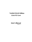
Physical Description
Front View
1
2
3 4
Disk 1
5
6
1
2
3
4
5
6
Disk 2
Power button and LED
Status LED
HDD activity LED
Restore Default button
Backup button
USB
Disk 3
Disk 4 can be installed inside the
chassis. See page 17 for information.
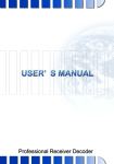
Rear View
LAN2 LAN1
USB 1 & 2
1
2
3
4
5
DO+ (12V)
DODI1+
DI1DI2+
Fan Outlet
Fan Outlet
GPIO
terminal block
6
7
8
9
10
DI2DI3+
DI3DI4+
DI4-
11
12
13
14
15
Power button 16
GND
RS232_TX
RS232_RX
GND
Power Switch
Power Cord
Socket
GND
NOTE:
DI*- (minus) stands for
Ground pins.
User's Manual - 7
VIVOTEK - Built with Reliability
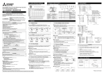
The digital output connection is diagrammed as follows:
DI-
DIVDC
DO+
DO+
DI+
BJT transistor
+12
VDC
Max.
Switch
DI+
DO-
BJT transistor
NO
NC
VDC
+12
VDC
Switch
DO-
AC
Source
NO
NC
AC
Source
Relay
Relay
AC
Device
AC
Device
The maximum load on DO pins is 50mA.
IMPORTANT:
It is important to leave a clearance of 10cm to
the rear side of the chassis. The clearance is
required to ensure an adequate airflow through
the chassis to ventilate heat. A 5cm clearance is
also required on the front of the chassis.
10cm
To ensure normal operation, maintain ambient
airflow. Do not block the airflow around chassis
such as placing the system in a closed cabinet.
5cm
8 - User's Manual
VIVOTEK - Built with Reliability
IMPORTANT:
For a RAID volume configuration, it is recommended you use hard drives of the same model
featuring the same capacity and rotation speed. It is also preferred that these drives are running
the same version of firmware.
Hardware Installation
SATA hard disk(s) are user-supplied. The network video recorder can readily accommodate
most of the off-the-shelf SATA hard drives.
1. Use the included bezel key to unlock the rotary bezel lock. Open the drive bay bezel by pulling the door latch to the side.
Bezel Lock
Door Latch
1
2
Bezel Lever
2. Install your hard disk to the drive tray. Gently put the hard disk into drive tray with its label
side facing up and the connector side facing
the inside of the chassis. Secure the hard
disk by driving screws from the bottom.
User's Manual - 9
VIVOTEK - Built with Reliability
IMPORTANT:
Avoid touching the hard drive's circuit board or connector pins. Doing so can damage the hard
drive by electro-static discharge.
3. Insert the hard drive into drive bay.
4. 4-1. Push the hard drive into bay until you feel the contact resistance.
4-2. Close the bezel lever to connect the hard drive to the back-end connector.
4-3. You should always lock the drive bezel when the drive bay is populated. This ensures the
hard drive is securely installed.
1
2
5. Repeat the process above to install more hard drives.
10 - User's Manual
VIVOTEK - Built with Reliability
Interface Connections
1 & 2. Connect CAT5e or better-quality Ethernet cables to cameras via a local, switched network, or clients through the Internet. Refer to next page for more information.
3. Connect USB devices such as USB optical drive or UPS.
4. Connect external digital input/output devices to the GPIO teminal block.
5. Make sure the power switch on the rear panel is in the OFF (O) position. Connect the supplied power cord to the power mains (100-240V AC, 50~60Hz).
Router
LAN/WAN
1
3
2
5
4
Power cord
DI/DO devices
USB devices
NOTE:
Cameras and the NVR must reside in the same subnet. Otherwise, the NVR will not be able to
recruit them as a recording configuration.
User's Manual - 11
VIVOTEK - Built with Reliability
Network Deployment
1. Connect network cameras to the NVR’s LAN ports.
2. Internet access to the NVR is made through the TCP port 80 and RTSP streaming via port
554.
16x
Clients
Router
Internet
Router
Switch
Router / Wireless AP
LAN
IMPORTANT:
1. The two LAN ports must not be managed by different DHCP servers or routers.
2. It is recommended all network cameras use static IPs. If you let a DHCP server assign IPs to
these cameras, IPs may be changed later and the NVR may not recognize them.
3. The NVR only receives H.264 and MPEG-4 video streams. If your cameras are configured to
deliver MJPEG streams, please change their video stream configuration.
4. The maximum recording bandwidth is 96Mbps using single disks or RAID0/1, and 48Mbps
using a RAID5 volume.
NOTE:
1. The two LAN ports can be configured into the same or different subnets, or into a failover or
load-sharing trunk group.
2. Client computers should support IE8 browser at a minimum of 1280x960 resolution or higher.
12 - User's Manual
VIVOTEK - Built with Reliability
Initial Configuration
1. Press the power switch on the rear panel to the ON (I) position. The NVR should start
immediately. To start the system again after the initial configuration, use the front panel power
button.
2.From a management computer, install the IW2 utility software included in the product CD.
Follow the onscreen instructions to complete the installation.
3. Start the IW2 utility. The IW2 utility will discover the NR8401 located in the same subnet.
4.Double-click on the NR8401 entry to start a
web session with the NVR system.
5. The login page will prompt. Enter "admin"
and "admin" as user name and password for
access for the first time. Click Login to begin
your configuration.
User's Manual - 13
VIVOTEK - Built with Reliability
6.The system will default to the LiveClient page. Click on the Settings button on the upper
right corner of the screen.
7.On the Settings page, click on Storage > Volume to access your storage volume
configuration.
8.On the Storage settings page, check if your hard drives are present and identified by your
system. Click on the Create... button.
14 - User's Manual
VIVOTEK - Built with Reliability
9.Depending on the number of hard drives you installed, a list of RAID volume configurations
will be listed. Select a configuration's check circle and the disk members of a volume, and
then click OK to continue. The initialization of a RAID volume will take several minutes.
Please refer to page 82 for more information about Storage configurations.
10. The initialization process will be indicated as follows.
11. When done, the RAID volume details will be indicated on the Volume screen.
User's Manual - 15
VIVOTEK - Built with Reliability
12. Click on Camera > General on the menu tree to open the camera settings page. Click on
the Search button to locate cameras installed in the subnet.
13. Cameras on the network will be listed. Click on the + button on the far left to enlist them into
your configuration. Click OK when done on this page. Click Save when you return to the
Camera page.
14. By default, cameras are configured to record all streaming at all time. You can change the
recording settings in Camera > Schedule.
15. Refer to the following chapters for more operation and configuration details.
16 - User's Manual
VIVOTEK - Built with Reliability
NOTE:
If you need to install 4 hard drives,
1. Power down the system and disconnect the power cord.
2.Open the chassis top cover by removing 4 screws from the sides, and then the hand screw at
the rear side of the chassis.
3. Remove the drive bracket by loosening 3 screws.
4. Orient the hard drive with its label side facing up and the connector side facing the front of
chassis.
5. Connect the SATA connector and SATA power.
6. Secure the hard drive to the bracket by driving screws from the sides.
#4 Drive Bracket
7. Install the drive bracket (along with the hard drive) back to the original location.
8. Re-install the chassis cover.
User's Manual - 17
VIVOTEK - Built with Reliability
Rack-mounting
IMPORTANT:
If you have either a round-holed or square-holed rack, install cage nuts or clip nuts to the
desired positions on the rack posts.
The instructions below are based on the installation to a 4-post equipment rack.
If you need to install the NVR system into a rack cabinet,
1. Install chassis ears to the sides of chassis using the included flathead screws. The rackmount rails are separately purchased.
2. Unpack the rack-mount rails' package, and detach the inner rails from the rail assembly.
Detach the inner rail by pressing on the release tab.
Release tab
Inner rail
18 - User's Manual
VIVOTEK - Built with Reliability
3. Secure the inner rails to the sides of the chassis using M4 screws.
4. Secure the L-shape brackets to the front- and rear-ends of outer rails using the black round
head screws and washers. Do not completely tighten the screws yet. Adjust the length of slide
rails by extending and matching the rails between rack posts.
User's Manual - 19
VIVOTEK - Built with Reliability
Adjusting the length of rails.
5. Secure the slide rails to rack posts using 8 M5 screws.
20 - User's Manual
VIVOTEK - Built with Reliability
6. Hold the chassis using hands on the sides of the chassis. Align the inner rails on the chassis
with the open portion of the slide rail assemblies. Push the system into the assemblies until
the system stops.
User's Manual - 21
VIVOTEK - Built with Reliability
7. The inner rails and the rail assemblies should be locked on the way into the rack cabinet.
Press the release tabs on the side to slide the chassis into rack.
Release tab
8. Secure the chassis to rack posts using a long M5 screw.
22 - User's Manual
VIVOTEK - Built with Reliability
Attaching Foot Pads
If you intend to place your chassis on a shelf or desktop, attach the foot pads
to the bottom of the chassis where you can find corner marks for reference.
LED Indicators
Name
Power button
LED
Status LED
Behavior
1
2
3
1
2
3
4
HDD LED
1
2
3
Default button
LED
Backup button
LED
1
2.
1
Off
Flashing Red
Constant Red
Constant Green
Flashing Green
Definitions
Powered down
Powering on
System is on
System is ready
Booting, proceeding with backup, restore, or restoring
default
Constant Orange System errors, system buzzer will also be sounded
Flashing Orange Errors occurred with backup, restore, or restoring
default
Constant Green Recording software is up and running
Flashing Green
Recording videos
Flashing Red
Connection errors, cameras disconnected, or no
volume is available.
Off
Not functioning
Flashing Green
Restoring system defaults
Off
Not functioning
Flashing Green
Backing up system configuration
HDD tray LEDs
Volume status
Read/write status
HDD tray LED (2) 1
2
3
4
Constant White
Off
Flashing Blue
Constant Blue
Hard disks are ready and configured into a volume
No hard disk is present
Read/write activities on hard disks
Drive is connected
User's Manual - 23
VIVOTEK - Built with Reliability
Power Up and Power Down
To power up and power down,
On the initial configuration:
1. Make sure the power switch on the rear panel is in the OFF (O) position, connect the power
cord between the system and power outlet.
2. Turn on the system by by turning the power switch to the ON (I) position.
After the initial connection,
1. Press the power button for 1 second to power on.
2. Press the power button for 1 second to power down. the system should start flushing the
cache contents in system memory and gracefully shut down.
3. If the power-down sequence does not proceed normally, press the power button for 4
seconds to shut down.
WARNING:
1. No storage system is completely fail-safe. Damage to data might occur due to file system
corruption, operating system malfunction, virus infection, HDD component failures, and so on.
Therefore, it is highly recommended to regularly back up your data, and VIVOTEK disclaims
responsibilities of data loss or recovery.
2. Always power off the system using the power button. Do not disconnect the power cord while
the system is still operating. Doing so will result in data inconsistencies. The normal power-off
procedure allows cached data to be written to disks.
NOTE:
If system buzzer is sounded, turn it off in Settings > Logs > Error page. Click the Stop
buzzer sound button.
Serious system faults, such as a missing volume, can trigger the system buzzer. Verify the
cause of system fault and turn off the buzzer.
24 - User's Manual
VIVOTEK - Built with Reliability
Chapter Two Login and Getting Started
2-1. Login
This is the login page on the browser. The minimum for resolution is 1280x960.
If you enable the IE7 compatible mode when using the IE8 browser, please disable the
compatibility function.
It is highly recommended that you should change the default user name and password. Please
refer to Settings > Security > User account page to see how to prevent unauthorized access.
The system will prompt you if you entered an incorrect user name or password.
Remember me: Your user name will be preserved in browser cookies for two days if you select
the Remember me checkbox. The user name will be automatically erased if you do not log in to
the system for two days.
User's Manual - 25
VIVOTEK - Built with Reliability
You may login to a different software utility by unfolding the
side panel on the Login button.
You can also select a different language using the
Multilingual selector menu on the lower left corner of the
Login screen. The functional items, menus, and dialogues
will then be displayed using the selected language.
Remember me:
Select the checkbox to save your user name for use
on the next login. The user name will be preserved
in browser cookies for two days. If you do not login
within the next two days, the user name will be
erased.
Login errors: below are the login errors that might occur.
A Login failure can result from the incorrect user name and passwords.
The No permission error occurs when a user logs in using an authentication that has no access
rights to the Settings page. He will then be re-directed to the Liveview page.
26 - User's Manual
VIVOTEK - Built with Reliability
Login options:
You may also mouse over the Login button to display the login options. You can then enter the
Liveview, Playback, or Settings window.
The NVR system features a very simple UI structure which consists of a Liveview window, a
Playback utility, and a system Settings window. Once logged in, you can move from one window
to another by selecting the hot link buttons on the upper right of the screen.
Liveview
Playback
Settings
User's Manual - 27
VIVOTEK - Built with Reliability
IMPORTANT:
1. Before operating the NVR, make sure you have properly installed hard drives and configured
the storage volumes. Otherwise, you will not be able to operate or try some of the system's
functionality.
2. Since the NVR system comes with 32-bit plug-ins for screen control, if your PC runs a default
64-bit IE browser and you manually enter the NVR's address on the browser, your browser
session may malfunction. Instead, if you double-click on the discovered NVR on the IW2
utility, a 32-bit IE browser will open.
3. When you log in to the Liveview or Playback interface to stream a live or recorded video,
install the ActiveX plug-ins. If it does not prompt when you log in, install plug-ins when you try
to playback a recorded video. You may then need to re-start the IE browser console.
28 - User's Manual
VIVOTEK - Built with Reliability
2-2. Graphical Layout and Screen Elements - Liveview
3
4
2
Layout
Layout contents Logo & Menu
1 Camera list
7
Alarm
panel
6
PTZ
panel
5 Viewcell panel
Once you log in, the system defaults to the Liveview page, which provides access to other
configuration utilities, live view screen, and other functional panels. The screen elements are
described as follows:
Item
1
Name
Camera List
Description
Provides a glimpse of all cameras inserted into your configuration. Basic
information is also provided along with a screenshot.
Provides access to various layouts
2
Layout
3
Layout contents Provides functions to extend, rotate, redo the layout, and control a DI/DO panel.
4
Logo & Menu
5
View cell panel Displays video streams from one or multiple cameras. Snapshot, streaming,
bookmark, and audio control functions are also available on individual view
cells.
PTZ panel
Exerts Pan/Tilt control on a selected view cell if the camera comes with
mechanical PTZ mechanism. Note that the use of joystick is currently not
available.
Alarm panel
Reports alarms transmitted via cameras' DI connections or those by the Motion
Detection, etc.
6
7
Provides access to the Playback and System Settings utilities, as well as
system time and logout function.
Each panel will be described in further discussions.
User's Manual - 29
VIVOTEK - Built with Reliability
2-2-1. Camera List Panel
The camera list displays the 16 recruited cameras by the sequential numbering order you
configured in the System Settings utility.
Sorting criteria
Camera thumbnails
Page switcher
Depending on the size and screen resolution of your monitor, the snapshots of 5 or 9 cameras
are displayed in this panel, and you should use the Page switcher buttons to see the rest of the
cameras. If a user logged in using a credential of a limited access, he may only see cameras
that he can access instead of all of the cameras.
To arrange a view cell layout, users can click and drag a camera to a view cell. Once connected,
a camera's video stream is displayed.
Camera Thumbnail:
A mouse click on the camera name under the thumbnail brings forth the summary of IP address,
model name, recording setup and DI/DO information.
Status
Snapshot
Camera index and camera name
30 - User's Manual
VIVOTEK - Built with Reliability
* Snapshot: the camera's image snapshot is replenished every 5 minutes. If a camera is
disconnected, the last image taken will be used to represent a camera.
* Camera index & Camera name: Placing the mouse cursor on top of a camera text displays
the camera index number and the camera name. You can click on the camera index to display
the information box.
* Status:
Online: the online status can be accompanied by the
DI/DO icon
Offline: camera is disconnected.
An unconfigured camera instance
Digial input is triggered
Connected and recording video to system storage
Connected with live streaming
Disconnected or trying to establish a connection
* Page switcher: Moves to the next page on the Camera list panel. The button will be grayedout if the end of the list is reached.
Sorting criteria
Use the sorting buttons to re-arrange the order of the cameras on the list. Cameras that match
the condition will be brought to higher places on the list (front of the order) regardless of its
original camera index.
Online: the online cameras.
Offline: the offline cameras.
Unconfigured camera instance
Cameras whose Digial inputs have been triggered
Cameras whose Digial outputs have been triggered
NOTE:
For online cameras, the snapshots on the camera list are refreshed by every 5 minutes, and
therefore may not represent the latest occurrences on the surveillance areas.
User's Manual - 31
VIVOTEK - Built with Reliability
2-2-2. Layout
1x1
1+3
1+5
2x2
By default, 5 typical layouts are provided for the user.
They include: 1x1, 1+3, 2x2, 1+5, and 4x4. System
default is the 4x4 layout. Cameras that do not fit into the
first page of a layout, say, a 2x2 layout, will be displayed
on the succeeding layout pages.
4x4
Each functional button on the screen is activated by a
mouse hover. For example, the below states designate
user's operation on a button:
User layout #1
1.
: not selected.
2.
: moused over, and is ready for selection.
3.
: selected, and is taking effects.
User layout #2
User layout #3
User layout #4
Because the maximum number of supported cameras is 16, the fifth and sixth view cells on the
3rd page of the 1+5 configuration will be unuseful.
Only an administrator can change and preserve a custom layout, and every user can designate
a specific layout to be displayed when he/she logs in. The default layout for each user is stored
in a browser's cookies.
Whenever changes are made to the current layout, a message prompt will appear on the side of
the layout panel reminding you to save your current setting.
Note that a user who did not log in as an administrator can change a layout, but his configuration
changes (with cameras inserted into view cells) will not be saved.
User Layouts
There are another 4 user layouts that can be individually
configured. An administrator can insert camera views into
these layouts, and save the configuration. These user layouts
can be seen by all users.
If you click the Rotate button before the configuration changes
can be saved, your configuration changes will be lost.
32 - User's Manual
VIVOTEK - Built with Reliability
2-2-3. Layout contents
A few functional buttons are available on the Layout contents page.
Clears all view cells on the current layout
Full view: extends the view cells on the current layout to the full of the screen.
Rotate: the rotate function lets system display successive layout pages by the
intervals of 10 seconds. The layout page that does not contain camera views will be
skipped.
A Rotate action will stop when you
1. move to another page,
2. move to a user layout,
3. click to select a view cell,
4. remove a camera from view cell.
DI/DO: displays the DI connection statuses and allows users to manually trigger a DO
signal.
If your current layout spans across multiple pages, use the arrow buttons to
switch from one page to another. The index number of the current page will be
shown between the arrow buttons.
When your current layout is displayed in a full view, move your cursor
to the left center of the screen to return to the default Liveview screen.
The Return button will appear.
2-2-4. Logo & Menu
A logout button, system time panel
, and 3 hot link buttons to access the Liveview,
Playback, and System Settings utilities.
The system date and time refers to the date and time kept on the
NVR system's real time clock.
Due to the limited space for the user name, user name may be
partially displayed until you hover your mouse cursor.
IMPORTANT:
Your configuration changes will be lost if you click one of the hot link buttons to move to another
utility window. For example, you have changed your Live View layout and then click on the
Playback button, you will enter the Playback window without saving your configuration. Save
your changes before you use these buttons.
User's Manual - 33
VIVOTEK - Built with Reliability
2-2-5. View Cell panel
A single view cell is shown below. Each view cell contains a video stream display area, an
information bar, and functional buttons at the bottom. A view cell is displayed in Normal,
Focused, or Maximized mode.
1. A single click selects a view cell from the View Cell panel, enables its function buttons, and
turn it into the Focused mode.
2. The 2nd click maximizes the size of the view cell to the full of the panel.
3. The 3rd click shrinks the maximized view back into the focused mode.
To deselect a view cell and return to the normal view, click on the Restore
lower right of the window.
button at the
Adding Cameras to View Cells
1. Click and drag a camera from the camera list to an unoccupied view cell.
2. Double-click a camera on the camera list. The camera will be added to the first unoccupied
view cell.
To deselect a view cell and return to the normal view, click on the Restore button at the lower
right of the window. You can also click on another view cell to continue adding other cameras.
34 - User's Manual
VIVOTEK - Built with Reliability
A view cell attempting to connect to a network camera will look like this. If the connection
attempt takes a long time, it may result from network problems or incorrect configuration with
video streaming. For example, you may have configured the camera to be streaming channel #2
using the MJPEG mode, which is not supported by the system. The NVR uses video stream #1
for recording, and stream #2 from cameras for live viewing. You should then open an individual
web console with the network camera to change its video streaming configuration.
IMPORTANT:
A camera can be inserted into multiple view cells. This way, a camera with a wide field of view,
such as a fisheye camera, can simultaneously display different regions of interest in different
view cells.
If the current layout already contain 16 cameras, the following message will prompt.
There can be more than 16 view cells across multiple layout pages, e.g., on the third page of the
1+5 layout. Placing a camera in the 17th or 18th view cell will bring out the following message.
User's Manual - 35
VIVOTEK - Built with Reliability
Information Bar
Status icon
Camera index Video time
Status icon Description
Connected with live streaming; a single click on this icon can trigger a manual
recording.
Connected and recording video to system storage.
Disconnected or trying to establish a connection.
NOTE:
If you disable the Manual recording
function on the Settings page, you
will not be able to use the Manual
Recording function on the Liveview.
A mouse hover over the status icon will produce the following messages:
1. "Connecting..." or "Cannot connect"
Connecting to a camera, or connection problem
might have occurred.
2. "Live streaming"
Video is being streamed.
3. "Recording"
Currently recording the video stream.
Camera index: an index number appointed to a camera following the order you inserted
cameras during the initial setup.
Video time: The time configured on the NVR system is displayed here.
36 - User's Manual
VIVOTEK - Built with Reliability
The time display formats are slightly different for different languages:
English
M/d/yyyy
H:mm:ss AM/PM
5/3/2011 1:07:05 AM
Deutsch
yyyy/MM/dd
HH:mm:ss
03.05.2011 01:07:05
Español
yyyy/MM/dd
HH:mm:ss
03/05/2011 1:07:05
Français
yyyy/MM/dd
HH:mm:ss
03/05/2011 01:07:05
Italiano
yyyy/MM/dd
HH:mm:ss
03/05/2011 01:07:05
yyyy/MM/dd
H:mm:ss
2011/05/03 1:07:05
日本語
Português dd-MM-yyyy
HH:mm:ss
03-05-2011 01:07:05
yyyy/M/d
H:mm:ss
2011/5/3 1:07:05
简体中文
繁體中文
yyyy/M/d
tt hh:mm:ss
2011/5/3 上午 01:07:05
tt 為上午/下午
Tool Bar Buttons
Buttons
Description
Resumes streaming.
Pauses a video stream.
Adds a Bookmark (that saves a short description and a one-minute footage from
the current feed)
Takes a snapshot.
Removes camera from the view cell.
Mutes (if there is audio input from the camera.)
Unmutes
Restores the view cell's original position on the Liveview panel.
Maximize the size of current view cell.
Activates the PiP function.
Disables digital zoom (PiP).
User's Manual - 37
VIVOTEK - Built with Reliability
Buttons
Description
Volume controller
Fisheye display modes - if the view cell contains video from a fisheye camera, the
fisheye display mode selector will be available:
1O: the orginal circular view.
1P: the panoramic view.
1R: the regional view.
Please refer to the fisheye camera's User Manual for more information.
Tool Bar Functions in Details
1. Play and Pause buttons:
These buttons pause and resume a video stream currently being played on your web browser.
Note that this operation does not affect the video recording taking place between a camera and
the NVR system.
2. Bookmark:
This function allows you to place a bookmark on a recorded stream when you observe a
situation from your live view window. The bookmark is preserved as a one-minute footage along
with a short description of a particular incident. The precondition of using this function is that
the video stream, while you are watching it on the view cell, must be recorded to the NVR at the
same time.
To add a bookmark,
1. Click on the button,
2. Enter a short description that can be as long as 120 characters.
Spotted
3. A confirm message will prompt at the lower right of the screen.
If the current video feed is not being recorded to storage, you will receive the following message:
Errors with creating bookmarks may also result from network and server errors.
38 - User's Manual
VIVOTEK - Built with Reliability
Below are two bookmarks (yellow tags) shown along with a recorded video in the Playback utility
screen. Bookmarks help find and retrieve important moments in a recoded video.
NOTE:
Bookmarks will be erased if the user/system erases the video clips they were appended to. For
example, system will recycle storage space by deleting old videos along with their bookmarks.
3. Snapshot:
This button produces a snapshot prompt. You may then right-click on the snapshot image to
save it to a preferred location.
Note that the size of a snapshot is equal to the frame size set for the video stream.
User's Manual - 39
VIVOTEK - Built with Reliability
4. Clear:
This button removes camera from the current view cell. The view cell will then be available for
other cameras
5. Mute and Unmute:
These buttons stops or resumes audio from a live stream.
6. Restore:
This button restores the view cell's original position on the Liveview panel.
7. Maximize:
This button extends the size of current view cell to the full of the Liveview panel.
8. Activate and Deactivate PiP function:
PiP is short for Picture in Picture, a function that provides digital zoom into a live video.
When activated, a Global view window will appear at the lower right of the view cell as shown
below. You can display only a portion of the complete video frame as an area of your interest.
Using a click and drag on the ROI window, you can instantly move to other areas within the
video frame.
You can resize the ROI window by a mouse hover on the lower-right corner of the window until
the resize mark appears. The default size of the ROI window is 25% of the Global view.
Click on the deactivate
button to close the PiP window.
Global view
ROI
Note that not every camera supports the PiP function. For example, the fisheye series cameras
do not support this feature.
NOTE:
The Talk function in the two-way audio is currently not supported.
40 - User's Manual
VIVOTEK - Built with Reliability
9. Volume controller:
The volume control takes effect when audio input from the network camera is available. Audio
is heard only from a focused window, one that you selected by a mouse click form the Liveview
panel. Some network cameras do not come with an embedded microphone, and its audio is
disabled by system default. The actual sound level is also dependent on the system volume of
the PC having a web console with the NVR.
The sound volume configuration will not be preserved when a camera is removed from a view
cell, web console is restarted, or when the Liveview layout is re-configured.
10. Fisheye display modes:
A view mode selector icon appears in a view cell of a fisheye camera. You can click to select a
viewing mode. The viewing modes are illustrated as follows:
1O (Original view)
1O View (Original View)
180° Hemispheric
1P (Panoramic view)
Swipe to scroll horizontally
User's Manual - 41
VIVOTEK - Built with Reliability
1R (Regional view)
1R View (Single Regional View)
Zoom In
Zoom Out
Zoom in/out
&
all-directional
navigation control
The 1R mode (or rectilinear) provides access to one image section within the hemisphere. You can
zoom in or out (using the mouse wheel or PTZ panel) or travel through to other areas within the
hemisphere using simple mouse clicks and drags. A single click on a particular object can bring the
object to the center of your view window. Click and hold down the left mouse button, and you can
swipe the view both horizontally and vertically.
Note that if your fisheye mounting type is set to the Wall Mount type, your screen control in the view cell
will be limited to 90° pan and tilt. Make sure your mounting type and camera settings have been properly
configured.
Because fisheye lens can cover a wide surveillance area, you can insert a fisheye camera into multiple
view cells, and let different regional views display in these view cells. In this way, you can have a glimpse
of multiple areas of interest, and the configuration of these different view windows will be preserved when
you save your layout settings.
42 - User's Manual
VIVOTEK - Built with Reliability
2-2-6. PTZ panel
The PTZ panel takes effect for cameras that come with mechanical PTZ functions. It does not
support digital PTZ functions. To utilize its functions, select a view cell populated by a PTZ
camera, such as a speed dome.
Depending on the individual functions that come with PTZ cameras, some functions will not be
available for every cameras. For example, the zoom controller will not apply for a PTZ camera
that comes without a mechanized zoom module, such as PD8136 and PT8133.
Preset location
selector
Pan/Tilt
controller
Zoom
controller
Auto
pan/patrol
controller
Focus
controller
Listed below are the camera models and the types of supported PTZ controls:
Model (series)
PT
VS (VS8102
and earlier)
VS84xx/88xx
PZ series
SD8xxx
SD7xxx
IP7xxx/8xxx box
camera
IP6xxx/3xxx/
2xxx box
camera
IZ series
Pan/tilt
controller
Yes
* Depends
Preset location
Zoom controller
Focus controller Auto Pan/Patrol
controller
Yes
Depends
No
Depends
No
Depends
Yes
No
Depends
Yes
Yes
Yes
Depends
Depends
Yes
Yes
Yes
Depends
Depends
Yes
Yes
Yes
Depends
Depends
Yes
Yes
Yes
Depends
Depends
Yes
Yes
Yes
Depends
No
No
No
No
No
Depends
Depends
Yes
Yes
Depends
* If the analogue cameras connected through the video server support PTZ mechanism.
NOTE:
On the the Liveview window, currently the Continuous Move and the Click-on-image functions
for PTZ cameras are not supported. Neither can you zoom in/out using the mouse wheel.
User's Manual - 43
VIVOTEK - Built with Reliability
PTZ presets: If your PTZ cameras have preset locations, click on the button to unfold the preset
menu. Click on any of the preset locations to move to the area of your interest. Refer to your
camera's User Manual for how to configure preset locations.
The following message will prompt if the camera has no
preset locations.
Pan/Tilt controller: A mouse hover over the arrow buttons activates the arrow button. Use the
buttons to navigate to a preferred location.
Zoom controller: The zoom controller buttons only apply to cameras that come with an optical
zoom module, such as a speed dome camera.
Focus controller: The focus controller buttons apply to cameras that come with focus control
over its lens module, such as a speed dome camera.
Auto Focus: If your camera supports the auto focus function, use this
button to acquire an optimal focus point.
44 - User's Manual
VIVOTEK - Built with Reliability
Auto pan/patrol controller: These buttons provides pan and patrol functions provides that
preset locations have been configured on the camera. For a speed dome camera, the pan
command tells the camera to continuously pan 360 degrees until stopped by a user command.
For PZ or PT series cameras, the pan action only takes place once to cover reachable areas.
The Stop button ends a pan or patrol tour.
2-2-7. Alarm panel
To receive alarms from cameras, you need to configure alarm triggers in the Settings > Alarm
configuration window (see page 99). Network cameras' digital inputs, digital outputs, or motion
detection, or NVR's digital inputs can all be used to detect conditions in external environments.
When the alarms are triggered, you can configure certain kind of actions to take place in
response to the alarms, such as:
1. recording the immediate video,
2. sending an Email,
3. sounding the buzzer,
4, sending snapshots to an FTP server,
5. sending event messages to web server,
6. moving camera lens to a preset location,
7. triggering an NVR/camera digital output.
The alarm panel displays the latest 10 alarm
entries with the latest alarm on top of the list.
The alarm list keeps up to 200 events. Older
events will be erased if the number exceeds
200.
The alarm panel is polled every 10 seconds. A mouse hover on an alarm entry displays full
information of the event.
Note that multiple alarms can be triggered by one incident. See page 99 for how to configure the
alarm settings.
User's Manual - 45
VIVOTEK - Built with Reliability
The alarm panel is displayed either in the list mode
or the icon mode
.
If an event is configured with a recording action, or the alarm is triggered when the associated
camera was recording to the NVR, there will be a play button to the left of the alarm message.
The alarm playback window will begin playback of footage from 10 seconds before the alarm.
The playback of an alarm-triggered recording will normally last for one minute. If, however, you
configured a shorter pre- and post-alarm recording time, your alarm recording may be slightly
shorter. The defaults for pre- and post-alarm buffer time are 5 seconds and 20 seconds.
Click and read a text-only alarm will turn off the alarm icon
. The alarm icons
unread alarms. The number of unread alarms will be listed on the title bar.
46 - User's Manual
indicate
VIVOTEK - Built with Reliability
You can click on the icon mode
button to have a glimpse of alarms indicated by their
snapshots taken by the time of the occurrences. If the alarm is triggered by NVR DI pins, no
snapshots will be available.
Move your cursor over an alarm with a recorded footage. The
Play button will become available.
The following buttons are available in the alarm playback window.
Buttons
Description
View live video: displays the live view streaming instead of the alarm recording.
Resumes the alarm playback.
Begins the alarm playback.
Pauses the current playback.
Mute or unmute the audio with the current playback. Drag the controller to
change the audio volume level.
Use the playback slider to quickly change the playback position.
User's Manual - 47
VIVOTEK - Built with Reliability
Incoming Alarms
New alarms will be indicated by the messages in bold letters, the alarm bell icons, and the
increasing number of unread messages
on the title bar.
A text-based history of past Alarms is accessed through the Alarm - History page in the
Settings window. See page 110 for information.
48 - User's Manual
VIVOTEK - Built with Reliability
2-3. Graphical Layout and Screen Elements - Playback
2
3
Layout
contents Logo & Menu
1 Camera list
6 Calendar
5
Alarm
panel
4
Playback panel
The screen elements of the Playback window are described as follows:
Item
1
2
3
Name
Camera List
Description
Provides a glimpse of all cameras that have recorded data. Basic information is
also provided along with a screenshot.
Layout contents Provides functions to extend, rotate, redo the layout, and for synchronous
playback.
Logo & Menu Provides access to the Playback and System Settings utilities, as well as
system time and logout function.
4
Playback panel Displays the playback functions. Snapshot, bookmark, and export functions are
also available on individual view cells.
5
Alarm panel
6
Calendar
Reports alarms transmitted via cameras' DI connections or those by the Motion
Detection, etc.
Shows when the recording took place, and thus enables users to quickly locate
a specific part of recording in history.
User's Manual - 49
VIVOTEK - Built with Reliability
2-3-1. Camera List Panel
The camera list displays the 16 recruited cameras by the sequential numbering order you
configured in the System Settings window. The elements in the Camera list on a Playback
window are identical to those on a Liveview window. Please refer to page 30 for details on the
Camera list panel.
There are two key differences between the Camera List on Liveview and that on the Playback
window:
1. Users can not click and drag a camera thumbnail to a playback view cell.
2. A double-click on a camera does not display video in a view cell. A double-click displays a
calendar where days with recorded videos are shown.
To begin playback and search for past recordings,
1. Double-click on a camera.
2. The Calendar panel will display the days video recording actually took place. And those days
will be highlighted by a blue background (as the 25th and 28th in the screen below.)
x2
1
2
50 - User's Manual
VIVOTEK - Built with Reliability
2-3-2. Playback Layout
3 types of layouts are provided for the Playback window. They include: 1x1, 2x2, and 1+3.
In the playback window, users can simultaneously playback up to 4 recorded videos.
Clears all view cells on the current layout
Starts or stops the Synchronous playback.
Full view: extends the view cells on the current layout to the full of the screen.
When your current layout is displayed in a full view, move your cursor
to the left center of the screen to return to the default Liveview screen.
The Return button will appear.
2-3-3. Logo & Menu
A logout button, system time panel
, and 3 hot link buttons to access the Liveview,
Playback, and System Settings utilities. This panel is identical to that on the Liveview window.
User's Manual - 51
VIVOTEK - Built with Reliability
2-3-4. Playback View Cells
The view cells in Liveview and Playback windows are similar. Their differences are listed as
follows:
1. 3 simple layout types are supported as previously discussed.
2. The information bar displays camera index and video time information only.
3. The Play and Pause buttons are not available on the Tool bar. One Export function is added
on a Playback view cell.
The functional buttons on an individual view cell are descrbed as follows:
Buttons
Description
Exports a section of the video into a 3GP or Windows exe file. The length of
exported video is configurable to 1, 3, 5, or 10 minutes.
Adds a Bookmark (that saves a short description and a one-minute footage from
the current feed)
Takes a snapshot.
Removes camera from the view cell.
Mutes (if there is audio input from the camera.)
Unmutes
Restores the view cell's original position on the liveview panel.
Maximizes the size of current view cell.
Activates the PiP function.
Disables digital zoom (PiP).
Volume controller
Fisheye viewing modes - if the view cell contains video from a fisheye camera, the
fisheye display mode selector will be available:
1O: the orginal circular view.
1P: the panoramic view.
1R: the regional view.
Please refer to the fisheye camera's User Manual for more information.
52 - User's Manual
VIVOTEK - Built with Reliability
Playback control panel
Timeline slider
Span of existing
recording
Control buttons
Playback info
Timeline zoomer
The time slide bar enables quick skimming through the recording. Its functional buttons are
described as follows:
Buttons
Description
Pause
Play. This button is available after you manually paused a playback.
Stops the current playback.
Next frame. After you paused a playback, use this button to browse video frame by
frame.
Speeds down by 1/2. The slowest speed is 1/8.
Speeds up. Increases the playback speed, to 2x, 4x, 8x, 16x, 32x, and then to a
maximum of 64x.
Displays the current playback status, such as Playing, Pause, or Stop.
Restores the view cell's original position on the liveview panel.
Maximizes the size of current view cell.
Activates the PiP function.
Disables digital zoom (PiP).
User's Manual - 53
VIVOTEK - Built with Reliability
Timeline zoomer. Use the zoomer to zoom in for more precise
skimming.
Timeline slider thumb. Click and drag this thumb button to move along and reach
a specific point in time. A click on the time line will also work.
The time line shows the length of existing recording taken on a specific time span. You can use
the timeline zoomer to scale down the span of time. For example, if the time span is reduced
to 1 hour, then each section on the time line represents 15 minutes of recording. The total time
span of a timeline starts from the minimal of 4 minutes, 20 minutes, 40 minutes, 1 hour, and up
to a maximum of 24 hours.
In Synchronous play mode, a change to the zoomer will be reflected by all synchronously
playing view cells.
Time span =12 hrs
Each section =3 hrs
Total time span
Time span =1 hrs
Each section =15 mins
If recordings take place by an event-triggered recording, the intervals between recordings can
be down to 1 minute, and the individual recordings will not be easily discernible. In this situation,
you can mouse over the timeline to pinpoint individual recording instances.
54 - User's Manual
VIVOTEK - Built with Reliability
2-3-5. Alarm Panel
The alarm panel displays the alarms or bookmarks recorded by the day of recording. Two
additional buttons are available: Page selector and Alarm filter.
Page selector
Alarm filter
See page 99 for how to configure
alarms.
• A playback button will be available with an alarm-triggered recording. The alarm panel in the
Playback window also supports the List mode and Icon mode that are similar to that in the
Liveview window.
• There can be numerous alarms occurring in a day. Use the page selector to display different
pages of alarm entries. Up to 200 entries can appear on one page. Note that the new alarms
that occurred seconds or minutes ago may not be instantaneously listed on the page.
If bookmarks are listed in the Alarm list, a bookmark entry will look like this:
Camera index. camera name (time) - bookmark
In the icon mode, a bookmark message will look like this:
Camera index. camera name bookmark, time of marking
Alarm filter:
Use the Alarm filter to find out specific alarms. Use the check circles below to narrow down
your search criteria by Alarm name, alarm type by Motion detection, DI, DO, or those manually
marked down as Bookmarks.
The alarm name is defined by users in the Settings
> Alarm page.
User's Manual - 55
VIVOTEK - Built with Reliability
2-3-6. Calendar Panel
Double-click on any of the existing cameras to display the Calendar panel. Days with recorded
videos will be highlighted in blue regardless of the length of existing recordings that occurred in
that day. You may then click on a day to begin viewing the past recordings.
1
2
3
4
You may use the arrow button to view the records in other months. If there are no recordings in
the current month, the recordings taken in the days of the following month will be shown stead.
56 - User's Manual
VIVOTEK - Built with Reliability
Chapter Three System Settings
The Settings window is accessed by clicking on the Settings button on the Logo panel.
You will enter the Overview of the Settings window. All the configuration menus are placed under
7 major categories: System, Network, Camera, Storage, Security, Alarm, and Logs. Click on
any of the menu shortcuts to begin configuration.
User's Manual - 57
VIVOTEK - Built with Reliability
Pnotify - During the configuration process, configuration errors or information will be indicated
by a small pnotify message boxes on the lower right of the screen.
3-1. System
3-1-1. System - General
The system general information window allows you to change the system host name, time zone,
system date and time, and set up a scheduled reboot of the system.
Note that if NTP time server configuration is preferred, you should configure all of your cameras
to listen to the same time server as those shown in the pull-down menu. You need to configure
camera settings over a web console, and set up the same configuration in the System >
General settings > System time page. The precondition is that the system must have access
to the Internet.
58 - User's Manual
VIVOTEK - Built with Reliability
The Schedule reboot device allows the system to clean up dirty cache by a scheduled reboot.
You can configure a reboot by a specific time within a week. Note that during the reboot the
video recording will be temporarily interrupted.
Scheduled reboot is an recurring event. Select the day within a week and a time for the reboot
using the checkboxes and drop-down menus.
3-1-2. System - Upgrade
If the need arises for updating system firmware, acquire the update from VIVOTEK's technical
support or download site. Locate the firmware binaries, and click Upgrade. The upgrade should
take several minutes to complete. Note that during the upgrade, the recording task will be
interrupted.
User's Manual - 59
VIVOTEK - Built with Reliability
3-1-3. System - Backup
On this window, you can perform 3 maintenance tasks:
1. Backup - You can backup your system configuration using the Backup function. Click
Backup, a message window will prompt. Click Save to preserve your system configurations.
Select a location for your backup file, then click Save to complete the process.
Note that the backup action does not involve the following:
1. Recorded videos and database,
2. Alarm records, bookmarks, and bookmarked footages.
60 - User's Manual
VIVOTEK - Built with Reliability
2. Restore - If you have a previously-saved profile, you can restore your previous configuration.
Click the Restore button.
A file location window will prompt. Location the backup file, and click Open. The Restore
process will take several minutes to complete, and system operation will be interrupted during
the process.
3. Restore Default - There are two kinds of defaults for the NVR systems: System defaults and
factory defaults.
The system defaults can be restored using the pushbutton on the system front panel. This
applies when users forget about its IP address or login password, while most other operation
details will remain unchanged.
The factory defaults (operated on this window) restores to its primitive state before shipping,
and hence users' configurations (such as host name, IP address, and layout settings) will be
erased.
Click Restore to restore your system defaults. A warning message will appear. Click OK to
proceed. The Restore process will take several minutes to complete, and system operation
will be interrupted during the process.
A successful operation will produce the following message.
User's Manual - 61
VIVOTEK - Built with Reliability
When Restoring the previous backup, the following should be noticed in terms of storage
configurations:
1. If storage configuration has not been changed, restoring configuration will not affect the
current storage configuration.
2. If changes have been made to storage configuration, the backup-restore action will not
displace the current storage configuration.
3. If users removed the current storage configuration, no storage volumes will be restored
after a backup-restore procedure. Users then must create new storage volumes to
proceed with recording tasks.
4. If users apply previous backup to a new NVR machine, system will detect the presence of
different hard disks, and no storage configuration from the backup file will apply.
5. If users move all hard disks and backup file from an NVR to another, storage
configurations will be stored on the new machine.
62 - User's Manual
VIVOTEK - Built with Reliability
3-1-4. System - Maintenance
This window displays basic information of various aspects, including CPU and memory usage,
LAN port operation and its bonding, disk drive temperatures, and UPS status.
The Reboot button is used to restart the NVR system.
The Reboot process will take about 2 minutes to complete.
The Refresh button polls the system for the latest system information as previously described.
User's Manual - 63
VIVOTEK - Built with Reliability
Pressing the Shutdown button will power off the NVR system. System will flush its cached
contents, and stop the recording and streaming tasks.
64 - User's Manual
VIVOTEK - Built with Reliability
UPS support
Once an UPS is connected via the USB interface, the NVR system supports the cooperating
protection against power outage. The UPS status [model name, status (Online or On battery),
battery charge level] is listed in the Maintenance page as shown below.
The NVR supports APC's Back-UPS and Back-UPS Pro series models.
Reactions on power outage:
When the UPS battery charge is lower than 10%, or can only sustain system operation for 3
minutes, the NVR system will automatically shut down. When the power source is restored, the
NVR system will automatically power up.
Back-UPS
On line
75%
User's Manual - 65
VIVOTEK - Built with Reliability
3-1-5. System - DI and DO
This window displays the digital input and output settings for the connections via the system's
terminal block. You can connect the sensor devices (such as a PIR sensor) to the termincal
block. The system will automatically detect the current connection as a high or low signal. You
can then define the normal status for the input or output pins.
66 - User's Manual
VIVOTEK - Built with Reliability
3-2. Network
3-2-1. Network - General
Two major configuration options are available here: Bonding mode and Address settings.
1. Bonding mode:
Make sure both of your LAN ports are connected to
network, and select one of the checkboxes below:
By default, the system network interfaces come in the
Standalone mode.
1-1. Failover - failover provides the capability to transfer network traffic through the
surviving LAN port if any of the two LAN ports is disconnected.
1-2. Load balance - Based on 802.3ad, Load balance enables two LAN ports to share the
load of network traffic. Non-layer 3 traffic, such as Multicast/boardcast requests will
be transmitted via one of the LAN ports. To best utilize this feature, you should use
a managed Gigabit Ethernet switch and have its 802.3ad link aggregation feature
enabled on the corresponding ports.
1-3. Standalone - When selected, different IPs will be assigned for each LAN port. The
NVR can be accessed via different subnets.
You may connect these ports to different subnets. For example, LAN1 to a router and
have the access to the Internet; and LAN2 to a private subnet. In this case, however,
you should appoint LAN1 as the default routing interface, so that Internet access is
available for DDNS settings or remote access.
User's Manual - 67
VIVOTEK - Built with Reliability
2. Address settings:
Get IP address automatically: Select this option to obtain an available dynamic IP address assigned
by the DHCP server each time the system is connected to the LAN.
Use fixed IP address: Select this option to manually assign a static IP address to the Network
Camera.
Enter the Static IP, Subnet mask, Default router, and Primary DNS provided by your ISP.
Subnet mask: This is used to determine if the destination is in the same subnet. The default value
is “255.255.255.0”.
Default gateway: This is the gateway used to forward frames to destinations in a different subnet.
Invalid router setting will fail the transmission to destinations in different subnet.
Primary DNS: The primary domain name server that translates hostnames into IP addresses.
Secondary DNS: Secondary domain name server that backups the Primary DNS.
When finished with the network settings, click on the Save button.
68 - User's Manual
VIVOTEK - Built with Reliability
3-2-2. Network - DDNS
VIVOTEK provides Safe100.net, as a free DDNS dynamic domain name service for users who
need access from the internet or a domain name service for the NVR. VIVOTEK maintains a
database of product MAC addresses for the Safe100.net service, and you can apply one domain
name for each NVR system.
Enable dynamic DNS service: Select this checkbox to enable the DDNS setting.
Make sure you have internet access. Click the Register button. The terms of service agreement window
will prompt. Click Accept to proceed.
In the Register column, fill in the Host name (xxxx.safe100.net), Email, Key, and Confirm Key, and
click Register. After a host name has been successfully created, a success message will be displayed
in the DDNS Registration Result column.
NOTE:
If one LAN port is connected to the Internet, and the other LAN port is connected to another subnet and
the default routing port is not set to the Internet port, the DDNS function will not be available.
User's Manual - 69
VIVOTEK - Built with Reliability
Enter a Host name, Email address, and password twice, and then click Register to proceed.
The acceptable characters for email address are: [0-9][a-z][A-Z][!][#][$][%][‘][*][+][-][/][=][?]
[^][_][`][{][|][}][~][.]. Two successive periods, [..], are not acceptable. The address filed can
accommodate up to 256 characters.
Use only alphabetic and numeric characters for the password. The maximum number of
characters is 64.
When completed, a confirm message will prompt. You will also receive a confirm Email. You
can now access your NVR system using the xxxx.safe100.net domain name address. Note
that access from the Internet should be routed to the private IP assigned to your NVR, using
methodologies such as port forwarding, etc. Successful and invalid input will display the
following messages.
Forget key: Click this button if you have forgotten the key to Safe100.net account. Enter host
name and Email address, and then click the Forget key button. Your account information will be
sent to your Email addres
70 - User's Manual
VIVOTEK - Built with Reliability
3-2-3. Network - Service
By default, the NVR service and video streaming are accessed via HTTP port 80 and RTSP port
554. You can designate a different port number if the need arises. Usually it is not necessary to
change these ports.
Instead of a web console, you can also access the NVR
and the subordinate cameras using the iViewer and
VIVOTEK's VAST software. The NVR can be managed as
one of the sub-stations in a hierarchical device structure.
Note that the password here should be identical to that
you use to log in to a VAST server. For iViewer, you log in
using the same user name and password for the login to
the NVR.
User's Manual - 71
VIVOTEK - Built with Reliability
3-2-4. Network - Utility
Use the test utility to test the connectivity with a network device, such as a camera. Test results
will be displayed by a message prompt.
Failure to reach a device displays the message below.
72 - User's Manual
VIVOTEK - Built with Reliability
3-3. Camera
3-3-1. Camera - General
The camera window provides management tools to recruit or disband cameras from your NVR
configuration.
1. Search:
The Search button allows you to locate all VIVOTEK cameras within a local network. Use the
check circles on top to display all cameras or only cameras that have not been recruited.
User's Manual - 73
VIVOTEK - Built with Reliability
On a listed camera, mouse over to the left of the entry to display the
Remove button.
the button. To deselect a camera, use the
Add button. Click on
Select a camera index number from the pull-down menu. The first unused number will be listed.
You may also select a different number or a number already appointed to another camera.
However, doing so will replace the existing camera.
Repeat this process to select more cameras in your deployment, and then click the OK button.
IMPORTANT:
If you select an index number already appointed to an existing camera for a new camera, the
recorded data taken from the existing camera will still be intact. However, the recorded data is
accessed through the same index number but using the name of the new camera.
New camera
Index no. taken by
an existing camera
74 - User's Manual
VIVOTEK - Built with Reliability
The legends used in the camera list are described below:
Modified
Selected
Move hover
(*) asterisk: An asterisk symbol indicates that a camera's settings have been modified.
(#) numbered:Camera index.
Name:
Camera name.
IP address: A valid camera configuration enables the IP address as a hyper link. You can
click on the hyper link to open an IE web console with the camera.
MAC address: A unique MAC address as that printed on the camera's label.
Model:
Camera model name.
Channel:
This indicates the stream number. If connected via a video server, the channel
number indicates the channel through which an analogue camera is connected.
A recent snapshot from the camera will also appear at the bottom of the camera list window.
User's Manual - 75
VIVOTEK - Built with Reliability
Left-click to select a camera, and edit the Connection and Recording configuration below:
1. Connection - You can rename the camera, and if your camera comes with password
protection, enter its User name and Password here. Otherwise, you will not be able to
manage or access the camera.
root
If preferred, the acceptable characters for a new camera name can be: [0-9][a-z][A-Z][_][-][ ].
The max. number of alphabetic and numeric characters is 64.
For a user name, the acceptable characters for a camera name can be: [0-9][a-z][A-Z][_][^][-][.]
[@][~][!][$][%]. The max. number of characters is 64.
76 - User's Manual
VIVOTEK - Built with Reliability
2. Recording:
2-1. Keep all recordings for maximum * days - determine the life span of recordings in your
system. Usually old recordings will be erased when the storage volumes become full.
When a storage volume is 90% full, the recorded videos taken on the oldest day (from
every camera) will be erased. Deletion of old files will stop when the used space falls
under 85% again.
When recycling takes place, the system buzzer will be triggered, and the recording task
can be halted temporarily until more storage space is regained.
2-2. Pre-alarm buffer time (seconds) - if the alarm-triggered recording is preferred, set up
a pre-alarm buffer for the system to record video before the occurrence of an alarm. The
configurable options are 3, 5, 10, 15, and 20 seconds. A 20MB memory space is reserved
for each camera, and therefore the pre-alarm buffer time can be shorter if the camera
video is recorded using a higher resolution.
2-3. Post-alarm buffer time (seconds) - if the alarm-triggered recording is preferred, set
up a length of time for the system to record video after the occurrence of an alarm. The
configurable options are: 10, 20, 30, 40, and 60 seconds.
2-4. Enable audio recording - Selected by default. Audio input is also recorded along with
the video. However, audio can be muted by default on some cameras. For example, a
speed dome camera requires the connection to an external microphone, and the audio
function is manually turned on through a managment session with the camera.
2-5. Enable manual recording - If this checkbox is deselected, you will not be able to enable
or disable manual recording from the Liveview view cells.
3. Delete:
To remove a camera from your list, left-click to select a camera on the list, and then click the
Delete button.
Note that once a camera is removed, all alarm settings related to the camera, such as DO and
preset location settings, will be erased.
User's Manual - 77
VIVOTEK - Built with Reliability
4. Save:
Click the Save button to preserve your configuration whenever changes are made to the
configuration or when you are leaving this page.
IMPORTANT:
Leaving the Camera - General page without saving your configuration, you will lose your
configuration changes.
78 - User's Manual
VIVOTEK - Built with Reliability
3-3-2. Camera - Video
The Video page determines the Liveview and recording streams of individual cameras in terms
of compression format, video resolutions, frame rate, and the constant bit rate settings.
The constant bit rate setting is especially important in that the sum of bandwidth consumed
for all recording streams must not exceed the 96Mbps threshold. The constant bit rate is like an
upper threshold placed on each video stream. The size of IP packets delivered from the network
camera will be maintained within the bit rate limitation.
If you configured a RAID5 volume as recording storage, the bandwidth threshold will be
48Mbps.
1. Video compression: The supported formats are: MPEG-4, H.264, and SVC. The MJPEG
format is not supported. If you change the bit rate and resolution settings of a camera,
the configuration applies to the camera firmware settings on its individual video stream. If a
camera becomes disconnected, your configuration change will not take effect util the camera
come online again.
2. Video resolution: The applicable video resolutions comes available in a pull-down menu. For
different cameras, the applicable resolutions can vary.
3. Frame rate: The applicable frame rate also varies from camera to camera. The list of
applicable frame rates is polled from individual cameras.
4. Constant bit rate: This places an upper threshold to limit the bandwidths consumed for live
viewing and recording streams. If "---" (not available) is shown, your camera stream might
have been configured using a "fixed quality" setting. You may need to open a web console
with it to convert the camera stream to be using the constant bit rate setting.
User's Manual - 79
VIVOTEK - Built with Reliability
3-3-3. Camera - Schedule
The camera recording schedule can be configured down to an hourly basis. The default settings
for cameras is to record videos at all time.
To set up a schedule,
1. Select a camera from the list using a single mouse click,
2. By default, all days and hours will be selected for continuous recording. If you want to disable
recording for specific time during a week, or enable event-triggered recording during some
time, use the Event recording and No recording buttons. Use them as a paint brush or
eraser on the weekly time chart. Click or drag your mouse cursor across the time chart to
change the recording schedule.
Change a non-recording hour to continuous recording by one click on the Continuous
recording button and then click and/or drag on the time chart.
1
- or -
2
3
The color codes for the display on the time chart are shown below:
Continuous recording
Event recording
No recording
80 - User's Manual
VIVOTEK - Built with Reliability
The Event recording is triggered by digital inputs or motion detection. You can click on the
setup button
to select or deselect the triggering options.
User's Manual - 81
VIVOTEK - Built with Reliability
3-4. Storage
3-4-1. Storage - Volume
With up to 4 disk drives, you have the following options for configuring storage volumes:
1. Single disk: The single disk configuration provides no fault tolerance. The system stores
video recordings to one or more single disk volumes in a consecutive order.
Single disks
Disk 0
Disk 1
Each single disk volume contains one disk drive.
Disk 2
2. RAID0: A RAID0 volume spreads data blocks of each file across multiple disk drives. The
volume provides no redundancy. RAID0 provides high performance by simultaneously reading
or writing to disk drives, but if a drive fails, all data within is lost. Select at least 2 disks to build
a RAID0 volume.
0
G
N/A
Disk 0
Disk 1
Disk 2
3. RAID1: A RAID1 volume provides high fault tolerance by writing the same data blocks
simultaneously to duplicate disks. Select at least 2 disks (or 4 disks) to build a RAID1 volume.
1
G
N/A
Disk 0
82 - User's Manual
Disk 1
VIVOTEK - Built with Reliability
4. RAID5: A RAID5 volume provides a balance in performance and good fault tolerance. RAID5
stripes data and also generates error correction information (parity bits). One drive’s capacity
is needed to store the error correction information from all member drives. A RAID5 volume
requires at least 3 disk drives.
Note that if a member drive fails, the rebuild process of a RAID5 volume can take about
several days to complete (using 2TB drive members). The rebuild runs in the background,
and the rebuild progress is indicated on the volume page.
G
Disk 0
Disk 1
Disk 2
On this configuration window, a "disk" refers to a physical disk drive, a "volume" refers to the
logical configuration of disk drives which may include multiple disk drives.
IMPORTANT:
If you remove a disk drive and insert it into a different drive bay, the system will consider it as a
new and different disk drive.
Some of the RAID levels provide data protection. Below is the summary of RAID level features:
RAID level
No. of HDD No. of HDD failure
Capacity
Allowed
>
=
RAID0
RAID1
2
2-4
RAID5
>
=
3
0
HDD # x (smallest HDD size)
1 or 2 (if counterparts in
HDD # / 2
the mirrored pair survives)
1
(HDD # - 1) x (smallest HDD size)
User's Manual - 83
VIVOTEK - Built with Reliability
The legends used in the Volume list are described below:
Selected
(*) asterisk: An asterisk symbol indicates that a volume's settings have been modified.
(#) numbered: Volume index.
Name:
Volume name.
Disk:
Member(s) of this volume.
RAID:
The RAID level by which this volume was made.
Total size:
Total usable capacity size in Gigabytes.
Available size: The unused capacity in Gigabytes.
Status:
The statuses can be: New, Online, Offline, Processing, Disabled, Error.
New: Individual disk drives have not been configured into usable storage volumes.
Online: The volume is ready.
Offline: A volume that has fatally failed, or its member drives are missing. Buzzer will be
sounded if a volume goes offline. Its sizes will then be indicated as unknown, "---."
Processing: A storage volume configuration is being processed.
Disabled: This volume has been disabled by users.
Error: Configuration or hard drive errors. The volume is invalid, and may need to be
manually removed.
Enable volume: It takes several seconds to disable a volume for the need to inform running
software and services and flushing cached contents.
To create a storage volume:
1. Click on the Create... button. Also check that if all your disk drives are listed. If properly
installed, they should all be listed in the Storage - Volume window.
84 - User's Manual
VIVOTEK - Built with Reliability
2. The Create volume window will
prompt. Select a RAID volume
configuration you prefer.
The available disk drives will then
be listed. Select their checkboxes to
include them into the volume.
The OK button will not be available
until you select the correct number of
disk drives; e.g., 3 or more disks for a
RAID5 volume.
3. If you create a RAID volume, the individual disk drives will be grouped into a logical volume
as shown below. The creation process should take several minutes, and is indicated in the
status bar below.
On completion, video feeds from network cameras are immediately recorded to the created
volume(s).
4. Click on the Save button to complete your configuration.
User's Manual - 85
VIVOTEK - Built with Reliability
To delete a storage volume:
1. Click to select a storage volume from the list.
2. Click on the Delete button.
3. A warning message will prompt saying all recorded data will be lost. Click OK if you want to
remove the volume.
The deletion progress will be indicated as below.
When completed, the status of the volume's member drives will be indicated as "New" drives.
As the result, all recording tasks to that volume will be cancelled.
IMPORTANT:
If you want to delete a RAID5 volume with a spare drive, remove the spare drive before you
delete the volume.
86 - User's Manual
VIVOTEK - Built with Reliability
To rebuild a storage volume:
The precondition is that you have a fault-tolerant storage volume made in a RAID5 or RAID1
configuration. A faulty drive is indicated by the front panel LED or messages in the system logs.
The White Volume LED on the drive tray will be turned off.
IMPORTANT:
Please carefully identify which disk drive has failed. Replacing the wrong drive in a logical
volume that already has a failed member will destroy the whole volume.
1. In System > Logs window, make sure which disk drive has failed. The sample screen shows
that Disk [3] has failed. A failed drive can sometimes be indicated as a removed drive.
2. Click to select the degraded volume, and then click on the Advance... button.
3. Select the faulty drive to set it as "Faulty." Click OK to proceed.
HDD tray LEDs
Volume status
Read/write status
A failed drive or a drive set as faulty will turn off its LEDs or the White I/O LED is off.
User's Manual - 87
VIVOTEK - Built with Reliability
On the Volume screen, faulty disk is indicated.
4. Replace the drive indicated as faulty. Open the bezel lock. Flip the door latch to the side and
then pull the bezel lever to remove the drive tray. Remove the HDD from the tray and replace
it with a new drive.
Bezel Lock
1
2
88 - User's Manual
VIVOTEK - Built with Reliability
5. Once the replacement disk is installed, click on the Advance... button again. Select the
replacement drive. Click OK to proceed.
During the rebuild process, further configuration of the volume will become unavailable. The
recording tasks will continue during the process. The following message will be shown if you
want to configure the volume during a rebuild.
User's Manual - 89
VIVOTEK - Built with Reliability
6. The rebuild process will start, and its progress is indicated by a progress bar in the Status
column.
The rebuild process can last for many hours using today's large capacity disk drives. The rebuild
process runs in the background and the recording tasks should continue.
To format a storage volume:
You may also format an existing storage volume in situations such as when you need to redeploy the system elsewhere.
90 - User's Manual
VIVOTEK - Built with Reliability
To add or delete a spare disk:
The spare drive option only appears when,
1. A 3-disk RAID5 volume is available.
2. An unconfigured new drive.
A spare disk (or standby disk) can immediately participate in the rebuild of a RAID5 volume,
saving the time for replacing a faulty disk. When in the "one-drive-failed" degraded mode, failing
another drive will destroy the volume. Using spare disk can reduce the chance of failing yet
another member drive.
To add a spare drive to a RAID5 volume,
1. Left-click to select a RAID5 volume, and then click on the Advance... button.
2. Select the unconfigured drive, disk #4 in this case, and then click on the OK button.
User's Manual - 91
VIVOTEK - Built with Reliability
3. The Add Spare process will take 3 to 5 minutes to complete, and the progress is indicated in
the progress bar below.
4. On completion, Disk 4 will be listed as a hot spare in the storage volume information.
NOTE:
Since RAID0 has no data protection, if a RAID0 volume has a failed member, the Advanced..
button will not be functional.
92 - User's Manual
VIVOTEK - Built with Reliability
3-4-2. Storage - Disk
The Disk window provides access to physical disk information, disk physical location, disk
health, polling for S.M.A.R.T. statuses, and bad block check.
(#) numbered: Disk index. This is determined by their loations in the chassis as shown by the
disk location graphics
on the lower right of the screen.
Model:
Disk model name.
Capacity:
Disk capacity in Gigabytes.
Status:
Disk operating status. Can be stated as:
Connected:
Identified:
Disk is properly installed, but not yet configured into storage
volume.
The storage volume this disk belongs to is operating normally.
Corrupted:
Disk is faulty.
S.M.A.R.T.:
S.M.A.R.T. status polled from the disk drive. This is not the results from a
manually-executed S.M.A.R.T. test.
Progress:
This shows the progress of drive S.M.A.R.T. test or bad block scan.
User's Manual - 93
VIVOTEK - Built with Reliability
1. Disk Information:
Model family: The brand name of the HDD manufacturer.
Device model: The disk model name.
Serial number: Serial number assigned to the disk drive.
Firmware version: The version of firmware running on this disk drive.
User capacity: The rated capacity for this disk drive.
Status: The bad block check or S.M.A.R.T. test previously executed on this drive.
2. S.M.A.R.T. test:
Attribute: The various attributes can vary from different HDD manufacturers.
Value: Value for the currently selected attribute.
Worst: Worst value acquired for that attribute.
Threshold: A predefined threshold or triggering value. The threshold below which the
normalized value will be considered exceeding specifications.
Raw vaule: The detected parameters for that attribute.
Status: The judgement made to deem the current reading as OK or failed.
3. Check disk:
Three types of check disk actions is initiated through this button. Select the action you wish to
take and click the OK button.
Bad block check: Performs read/write test to drive sectors to locate bad blocks. This action
may take several hours to complete.
Short test: Tests the electronic and mechanical performance and disk read performance,
including those on disk buffer, read head, seek time, and integrity of drive sectors. The short
test is performed on a small section of disk platters, and takes about 2 minutes to complete.
Long test: The long test is more thoroughly and is performed to all drive sectors. The actual
completion time depends on drive sizes and the attributes put to test.
The Check disk functions mentioned above, when performed during active I/Os, can consume
system resources and cause dropped frames with the recording tasks.
4. Stop check disk:
Stops the bad block check or S.M.A.R.T. test on an individual disk drive. The disk drive
currently running a disk check should have a progress bar shown in the Progress column.
94 - User's Manual
VIVOTEK - Built with Reliability
3-5. Security
3-5-1. User account
The User account window allows you to create more uers, to change user password, and
place limitations on users' privileges and administration rights. Up to 16 users can be created,
including the default administrator.
1. By default, there are two user groups: Administrator and Normal user.
2. The normal users can not access the Settings window, meaning that normal users can not
add or remove cameras, make changes to alarm, network, and all other system settings.
When a normal user tries to access the system Settings window, the following message will
prompt.
3. The administrator users can access all cameras recruited in the configuration; while the
normal users can be configured to have access to some or all cameras.
4. The system blocks out the video feeds from users who are denied of the access to particular
cameras. The alarms and the alarm-triggered recordings from those cameras will also be
inaccessible for unauthorized users.
To create users,
1. From the Security > User account window, click on the Create... button.
User's Manual - 95
VIVOTEK - Built with Reliability
2. Select a User group by unfolding its pull-down menu. Select either an Administrator or normal
user as the user group.
3. Enter the User name and password. The max. number of characters for a user name is 64,
with alphabetic and numeric characters including [0-9][a-z][A-Z][_][ ][-][.][,][@]. The max.
number for password is also 64.
4. If you are creating a normal user with limited access to cameras, deselect the checkboxes in
front of the cameras to deny the user access.
5. Click OK to close the configuration window. Repeat the process to create more users, and
please remember to click the Save button to preserve your configuration after you created all
users.
To remove users,
1. From the Security > User account window, left-click to select an existing user.
2. Click on the Remove button.
3. The user's entry will appear in lighter color with a strike-through to distinguish it as a deletion
that has not been applied.
4. Click on the Save button, and then the deletion will actually take place.
96 - User's Manual
VIVOTEK - Built with Reliability
To change the password for an existing user,
1. From the Security > User account window, click on an existing user.
2. click on the Change password... button.
3. The password prompt will appear. Enter the new password twice and click OK to confirm.
4. The user's entry will appear in a lighter color and an asterisk mark in front to distinguish it as
a changed entry that has not been applied.
5. Click Save to preserve your changes on the screen.
User's Manual - 97
VIVOTEK - Built with Reliability
3-5-2. Access list
The access control applies to the access from a web client over HTTP and RTSP protocols.
Three access configuration options are available:
1. Allow all: Allows access from all IP addresses.
2. Allow only: Allows access only from the listed IPs. You should manually enter the IPs for
computers that need to access the NVR.
Note that you can use the asterisk (*) mark to represent all decimal numbers in each
individual octet of the range of IP address: such as using 172.16.0.* for addresses ranging
from 172.16.0.1 to 172.16.0.254.
A decimal number between two asterisks, e.g., <172.*.10.*>, is considered as invalid.
3. Deny only: Denies the access from the listed IPs. You should manually enter the IPs for
computers that will be blocked out from the access. The configuration details is the same as
those for the Allow only methodology.
98 - User's Manual
VIVOTEK - Built with Reliability
3-6. Alarm
3-6-1. General
The events reported from individual cameras' digital inputs, digital outputs, and motion detection
can be accommodated in the NVR system's alarm settings. The NVR also comes with DI and
DO pins. These events will then be reported or commanding to trigger corresponding actions as
follows:
1. Reporting events via Email or system buzzer.
2. Triggering video snapshot and text message by the occurrences of events to an FTP/HTTP
site.
3. Triggering the camera(s) for its lens to move to a preset position.
4. Triggering the cameras' or the NVR's digital output.
5. Alerting the administrator with alarms indicators on the Alarm panel.
You can create up to 16 instances of alarm.
Hardware connections to DIs or DOs, e.g., window sensors, should be made separately. The
motion detection configuration is also made via a web console with individual cameras.
7
Digital input/output
Motion detection
VIVOTEK Network Cameras
6
Preset positions
Events triggered
LAN/WAN
4 FTP
5 HTTP
Web Console
Alarms
7
Digital input/output
2
7
Email
NR8401
3
Buzzer
1
Event-triggered
recording
User's Manual - 99
VIVOTEK - Built with Reliability
Below is a glimpse of alarm sources and alarm actions:
Sources
Actions
DI
►
Video recording
DO
Email
Motion detection
Buzzer
FTP
HTTP
Camera preset points
Camera/NVR DO
►video footage
►snapshots
►snapshots
►messages
To create an alarm,
1. Click on the Create... button.
2. The Create Alarm wizard window will prompt. You can manually enter a name for the current
setting. You can enter up to 16 numeric or alphabetic characters for the name, including
symbols such as [0-9][a-z][A-Z][_][ ]. You can also designate the interval between one alarm
and the next triggered alarm to avoid the situation that the alarms can be too frequently
triggered.
100 - User's Manual
VIVOTEK - Built with Reliability
The Activate alarm checkbox is selected by default. Click on the Next button to proceed.
3. On the Source window, select one or more cameras by selecting its checkboxes. The number
of DI or DOs on each camera is automatically detected and displayed through individual
checkboxes. The Motion detection function, if there are many detection windows configured
on a camera, is all triggered by one checkbox.
Note that the triggering sources will be listed even if the camera is currently not connected.
User's Manual - 101
VIVOTEK - Built with Reliability
4. On the Action window, you can select the Action type from a drop-down menu. The
configuration details of each action type is discussion below.
4-1. Recording - When an event is triggered, the selected camera will record a video footage
of the length defined by the pre-/post-event setting, to the NVR system. See below for an
Alarm playback window.
Once an alarm is triggered, it is listed on the Alarm panel on the Liveview window. See page
45 for details about the functions of alarm panel and the alarm playback function.
102 - User's Manual
VIVOTEK - Built with Reliability
4-2. Email - The Email action sends an Email to the administrator along with a snapshot of
the event.
To configure Email notification, enter valid Email addresses as the Sender and Recipient
addresses, an Email subject, and the SMTP server address through which the Email will
be delivered. If you need to log in to SMTP server to deliver an Email, enter the User
name and password for access to that account.
The Email subject and addresses can be composed of 254 characters in numeric or
alphabetic characters including: [0-9][a-z][A-Z][_][ ][-][.][,][@]. You can enter the addresses
of multiple recipients. Use semicolons, (;), to separate the addresses of multiple
recipients.
Select the checkboxes below for which camera's snapshots will be sent along with the
Email.
The file names of the snapshot jpeg files will look like this:
[MAC]_[DATE]_[TIME]_[CAMERA_INDEX].jpg
User's Manual - 103
VIVOTEK - Built with Reliability
4-3. Buzzer - The buzzer is sounded on the occurrence of the event. The buzzer tones
are categorized into: Major (1 long 2 shorts), Normal (3 shorts), and Minor (2 shorts)
depending on the importance of an event. Select a Buzzer modulation from the dropdown list. A long tone has a duration of 1 second, while a short tone 0.5 second.
Select how many times the buzzer tones will be repeated on the occurrence of an event.
If events of different importance are issued at the same time, e.g., one major and one
minor event, system will ignore the minor event and sound the buzzer tone for the major
event only. The buzzer can be sounded either by the Alarm actions or the system events.
If Alarm actions and system service events occur at the time, Alarm actions have the
higher priority.
If multiple Alarm actions occur, the currently-sounded events can be depleted by the new
event.
NOTE:
If system buzzer is sounded, turn it off in Settings > Logs > Error page. Click the Stop
buzzer sound button.
Serious system faults, such as a missing volume, can trigger the system buzzer. Verify the
cause of system fault and turn off the buzzer.
104 - User's Manual
VIVOTEK - Built with Reliability
4-4. FTP - Snapshots from specified cameras can be uploaded to an FTP site on the
occurrence of an event. Enter the FTP site address in the dotted-decimal notation, e.g.,
159.22.151.20. Enter the login name and password for the user account. You can enter
a directory name you prefer on the FTP site. The server port default is 21, a different
number between 1025 and 65535 can also be assigned.
If authentication is not applied, login will proceed using the [anonymouse] account.
The file names of the snapshot jpeg files will look like this:
[MAC]_[DATE]_[TIME]_[CAMERA_INDEX].jpg - If similar files already exist, an
additional index number will be added to the end of file name.
User's Manual - 105
VIVOTEK - Built with Reliability
4-5. HTTP - An event message is sent to an HTTP server on the occurrence of an event. The
URL format for the HTTP server address is http://host{:port}[abs_path]. The applicable
characters for the abs_path are: [0-9][a-z][A-Z][-][.][:][/][?][&][@][_][=].
If you need to log in to HTTP server, enter the User name and password for access to
that account.
The user name can be composed of 64 numeric or alphabetic characters and symbols
including [0-9][a-z][A-Z][_][ ][-][.][,].
106 - User's Manual
VIVOTEK - Built with Reliability
4-6. Camera preset points - A PTZ capable camera can move its lens to the preset position
in case of a triggered alarm. For example, a triggered sensor may indicate an area of
interest has been intruded, and a camera's field of view should be moved to cover that
area. The precondition is that you properly set up preset positions on your PTZ cameras.
4-7. Camera DO - A triggered alarm triggers a camera's DO, e.g., an alarm siren.
4-8. NVR DO - A triggered alarm triggers the NVR's DO, e.g., an alarm siren.
User's Manual - 107
VIVOTEK - Built with Reliability
5. On the Schedule page, you can select to activate or de-activate alarm triggers throughout a
specific time. For example, in some situations you can disable the alarm triggers during the
office hours, and choose to enable the triggers only during the off-office hours.
1
2
3
6. Click Finish to end the configuration. A configured instance will appear in lighter color and an
asterisk mark in front to distinguish it as a changed entry that has not been applied.
7. Click Save to preserve and enable your alarm setting.
8. Repeat the process above to create more alarms according to the needs in your surveillance
deployment.
108 - User's Manual
VIVOTEK - Built with Reliability
3-6-2. Editing Alarms via Source, Action, and Schedule
1. Editing an existing instance 1-1. To remove an existing alarm, select by a left-click, and then click on the Remove button.
2
1
1-2. To edit an existing alarm, select by a left-click, and then click on the Source, Action,
or Schedule button on the left function tree. The associated parameters will display
on different windows. You can then edit the previous configuration such as selecting a
different triggering source, reactive action, or time span on a schedule.
1
2
3
While in the editing window, the Create and Remove buttons are not available.
User's Manual - 109
VIVOTEK - Built with Reliability
3-6-3. Alarm - History
The History window provides access to search for past alarms.
You can designate your search cirteria by the triggering devices, by the time of occurrence, or
by the Event types such as Motion detection, DI, or DO. Note that the time search can only be
dated back to 180 days ago.
The search results will be listed on the right with index number, time of occurrence, alarm name,
and the Event type. The search results will display up to 200 entries. The outdated entries will
be depleted.
110 - User's Manual
VIVOTEK - Built with Reliability
3-7. Logs
By defaults, system logs will be written to every disk drives installed into the system. Up to
10,000 event logs will be kept with a segmented disk section within each drive. Old logs will be
automatically removed if exceeding the 10,000 threshold.
The logs related functions include:
1. Export button: This button can be used to export the current event logs in the CSV format.
The default export file name is [MAC]_[DATE]_[TIME].csv. For example, an exported file
may look like this: 0002D1112233_20130222_011013.csv.
2.
Page selector buttons: (from left to right) First page, Previous page, Next page,
and the Last page.
3.
Page size buttons: These buttons determines how many event
logs will be displayed on a single page. The selected number will be displayed without the
underline.
The event logs fall into he following categories: System, Recording, User, and Error. A click on
each category brings out a list of event logs belonging to that category.
Usually the Error events can trigger the onboard buzzer. Use the Stop buzzer sound button
to mute the buzzer. The will buzzer will still be sounded if the system is powered off and then
powered on until the errors can be corrected, such as a missing volume.
User's Manual - 111
VIVOTEK - Built with Reliability
The following information is shown with each event log:
1. Level: The following severity level can be applied to an event.
1-1. Error: Configuration errors such as lack of system memory or a faulty camera password.
1-2. Info: General information such as acquiring an IP from DHCP server.
1-3. Warning: Configuration and operation errors such as re-starting server service.
1-4. Config: Events that are generated due to configuration changes, such as a change in
address or that to a camera configuration.
Below are some sample messages:
Event
Level
Source
Message
DHCP renew
address
Info
[service name]
DDNS result
Reboot
System
shutdown
Restore
NTP time update
Disk insert
Disk remove
Firmware
upgrade
Recycle start
Info
Info
Info
[service name]
User: [username]
Power button
DHCP renew:
interface: [interface]
Address: [IP address]
Subnet mask: [subnet mask]
Gateway: [gateway]
DDNS result: [OK/Failed]
System reboot
System shutdown
Info
Info
Info
Info
Info
User: [username]
[service name]
[service name]
[service name]
User: [username]
Restore configuration
NTP time update: [time offset]
Disk inserted. [disk id]
Disk removed. [disk id]
Firmware upgrade
Info
[service name]
Recycle start
Info
[service name]
Recycle start:
[volume name] [volume size] [volume
free]
Recycle finish:
[camera id] [expired date] [recycle
date]
112 - User's Manual
VIVOTEK - Built with Reliability
Recycle finish
Info
[service name]
Recycle fail
error
[service name]
Recycle finish:
[volume name] [volume size] [volume
free]
Recycle fail: Disk space is insufficient
User's Manual - 113
VIVOTEK - Built with Reliability
Chapter Four Operation
IMPORTANT:
1. Before operating the NVR, make sure you have properly installed hard drives and configured
the storage volumes. Otherwise, you will not be able to operate most of the system's
functionality.
2. Since the NVR system comes with 32-bit plug-ins for screen control, if your PC runs a default
64-bit IE browser and you manually enter the NVR's address on the browser, your browser
session may malfunction. Instead, if you double-click on the discovered NVR on the IW2
utility, a 32-bit IE browser will open.
4-1. Liveview
4-1-1. Placing Cameras into the Layout
Legends and definitions of icons on the layout panel have been described on page 32.
It is presumed that you have properly inserted all network cameras in your deployment as
previously described on page 73. All 16 cameras should be listed on the Camera list.
Camera list
Note that layout design can only be performed by the system administrator.
114 - User's Manual
Layout
Layout contents
VIVOTEK - Built with Reliability
To begin the design of your layout,
1. Select a layout pattern by a single click. The options are: 1x1, 1+3, 1+5,
2x2, and 4x4.
1
3
2. Click and drag cameras from the Camera list to empty cells on your layout. Repeat the
action until you placed all your cameras into the layout. You may also double-click on a
camera's thumbnail to fill it into the first unoccupied view cell.
2
Camera list
3. When you filled up the current layout, e.g., 6 camera into the 1+5 layout, click the page
switch button to continue on the next layout page.
User's Manual - 115
VIVOTEK - Built with Reliability
4. When you are done with the current layout design, i.e., the user layout 1, click Save to
preserve your settings. This message prompts on the screen whenever any change is made
to the current layout.
5. You can create more user layouts by mouse-overing the user layout button. You may create
more user layouts for different purposes, such as for the use of different users, or playing
different views of a fisheye camera on multiple view cells.
The fisheye mode button is available on the view cell where you inserted a fisheye camera.
When a regional view is displayed, the shooting angle and image orientation is kept with the
layout. See page 41 to see more about fisheye viewing modes.
116 - User's Manual
VIVOTEK - Built with Reliability
Placing different regional views of a fisheye camera into view cells will look like this:
1R View
(Single Regional View)
NOTE:
Only an administrator can alter the display
modes of fisheye cameras. Although ordinary
users can make changes to a regional view,
his changes will not be preserved after a
console is re-started.
In addition to fisheye cameras, if a camera has a wide field of view, you may also display its
different fields of view in multiple view cells. Some view cell may also contain a PiP view that is
digitally zoomed.
If users were created and some cameras are excluded from their access, a user may log in
and see the locked-on cells as shown below:
A user who has limited access rights may still re-arrange the layout of view cells. However,
his configuration change will not be saved after he leaves the current console.
User's Manual - 117
VIVOTEK - Built with Reliability
NOTE:
By default, every users or administrator logs in to the Live view window to the last layout page
he visited. The last layout page a user visited during the previous console becomes the default
layout.
4-1-2. PTZ and Other Screen Controls
Note that the PTZ control panel only applies when you select a view cell with a camera that
comes with mechanical PTZ functions. Currently the e-PTZ function is not supported by the
NVR system.
With a PTZ camera, the buttons on the PTZ panel become functional when you mouse over
its GUI elements. For all compatible cameras and exerting Zoom, Focus, and Patrol functions,
please refer to page 43 for details. The Zoom function, for example, requires a camera that
comes with a motorized zoom module, and may not be applicable to every PTZ camera.
The preset positions and the patrol functions require the associated configuration on the
cameras via a web console. Before you make use of these functions, you should set up
the preset positions on a web console with the camera. The NVR GUI does not provide the
configuration options with PTZ preset positions.
You can use Preset button to display preset
positions and tell the camera to move and
point at the preset direction, and to perform
a camera tour to visit these positions in a
consecutive order.
118 - User's Manual
VIVOTEK - Built with Reliability
To access live view control,
1. Click on a view cell. The view cell will become a focused view cell. The streaming control
buttons will be listed at the bottom of a view cell. These buttons have been discussed on
page 37.
2. The 2nd click on a view cell enlarges it to the full of the live view area. The 3rd click
reduces its size to the original focused view.
3. To deselect a view cell, you can click on another view cell in the display area or click on the
button.
Restore
A selected, focused,
view cell.
NOTE:
If you have concerns with the display quality and frame rate per second, refer to page 79 for
how to configure video feeds for live viewing as well as for video recording. The configuration
options can be found in Settings > Camera > Video.
Note that the constant bit rate methodology is applied in this system and it sets an upper
threshold on the size of IP packets sent with the video streams. Image quality will be slightly
compromized if reaching the ceiling of allowable bandwidth.
User's Manual - 119
VIVOTEK - Built with Reliability
To place bookmarks and exert screen controls,
On a focused view cell, you can temporarily stop or start an ongoing streaming, or place a
bookmark
that saves a short description and a one-minute footage from the current feed.
The bookmark is also displayed along with the recorded video, and therefore it is easier to look
for a specific moment in time when you need to trace back for a scenario later.
The bookmark function can be executed on a live or recorded stream when you observe a
situation from your Live view or Playback window. The precondition of using this function is that
the video stream, while you are watching it on the view cell, must be recorded to the NVR at the
same time.
To add a bookmark,
1. Click on the button,
2. Enter a short description that can be as long as 120 characters.
3. Click on the + button or simply press Enter on your keyboard.
2
1
120 - User's Manual
3
VIVOTEK - Built with Reliability
To Activate and Deactivate PiP function,
PiP is short for Picture in Picture, a function that provides digital zoom into a live video.
When activated, a Global view window will appear at the lower right of the view cell as shown
below. You can display only a portion of the complete video frame as an area of your interest.
Using a click and drag on the ROI window, you can instantly move to other areas within the
video frame.
You can resize the ROI window by a mouse hover on the lower-right corner of the window until
the resize mark appears. The default size of the ROI window is 25% of the Global view.
Click on the deactivate
button to close the PiP window.
Global view
ROI
Note that not every camera supports the PiP function. For example, PTZ cameras and fisheye
cameras do not support the PiP feature.
Refer to page 37 for GUI legends and individual functionality.
4-1-3. Audio
Audio is only transmitted through the camera in a view cell that is currently selected. You can
manually tune the volume level, mute, or unmute the audio feed through a view cell.
User's Manual - 121
VIVOTEK - Built with Reliability
4-1-4. Camera Properties and Controls
You can click on the underlined name entry of a camera on the camera list to open its properties
window. Here you can find a short description of the camera name, address, and model name.
You can also enable or disable the scheduled or continuous recording set for the camera. Click
on their associated icons, , , to change their recording status.
For a camera that is not performing a continuous recording, you can click on the Manual
Recording button, , to start a manual recording. The recording will stop using the same
button.
You can also manually turn on the digital output
connected to a specific camera.
122 - User's Manual
, e.g., to trigger an external alarm that is
VIVOTEK - Built with Reliability
4-1-5. Alarm Panel
To receive alarms from cameras, you need to configure alarm triggers in the Settings > Alarm
configuration window (see page 99). Network cameras' digital inputs, digital outputs, or motion
detection can all be used to detect conditions in external environments. You can configure
certain kind of actions to take place in response to the alarms: such as
1. recording the immediate image,
2. sends an Email notification,
3. sounds the onboard buzzer,
4, sends snapshots to an FTP server,
5. sends videos to web server,
6. moves camera lens to a preset location,
7. triggers a camera's digital output.
The operation details of the Alarm panel and Alarm Playback utility have been described on
page 45.
User's Manual - 123
VIVOTEK - Built with Reliability
4-1-6. Layout view Control Buttons
1.
When editing a user layout, you can use this button to clear all view cells of inserted
cameras.
2.
This button extends the current layout to the full of the screen.
3.
The Rotate function lets system display successive pages in a user layout by the
intervals of 10 seconds. The layout page that does not contain camera views will be skipped.
A Rotate action will stop when you
1. move to another page in the user layout,
2. move to another user layout,
3. click to select a view cell,
4. remove a camera from view cell,
5. click to disable the rotation function.
to
When your current layout spans across multiple pages, use the arrow buttons
switch from one page to another. The index number of the current page will be shown between
the arrow buttons.
4.
The DI/DO panel displays the current digital input conditions and the manual trigger DO
button. When a DO is triggered, it is indicated by a white circle. Click on the circular button in
front of DO to trigger a DO signal.
A DO signal can also be associated with
the Alarm setting for the NVR to take
related actions, such as the Alarm
recording.
Note that once triggered, the DO signal
will be continuous and the DO-triggered
events will prompt continuously. Click on
the DO button again until the white circle
disappears.
124 - User's Manual
VIVOTEK - Built with Reliability
4-2. Playback
The elements in the Camera list on a Playback window are similar to those on a Liveview
window. Please refer to page 30 for details on the Camera list panel.
However, on a Playback window, you can not:
1. Users can not click and drag a camera thumbnail to a playback view cell.
2. A double-click on a camera does not display video in a view cell. A double-click displays a
calendar where days with recorded videos are shown.
4-2-1. Begin Playback and Search for Past Recordings
1. Select a layout. You can display the playback views of multiple cameras on one screen.
2. Select a view cell on the Playback window,
3. Double-click on a camera.
4. The Calendar panel will display the days video recording actually took place. And those days
will be highlighted by a blue background (as the 25th and 28th in the screen below.)
NOTE:
If a video stream is recorded in the MJPEG format, it will not be playable
on the Playback window.
1
x2
1
2
User's Manual - 125
VIVOTEK - Built with Reliability
4-2-2. Past Alarms and Bookmarks
When you selected a day when alarms took place on a camera, the alarms will be listed on
the Alarm panel. Up to 200 entries can be listed on a single page, and a max. of 1,000 entries
across multiple pages.
You may then,
1. Mouse over the alarm thumbnails and click on the play button. The Playback window will then
play back the video recorded by the time of the occurrence.
2. Unlike the Alarm playback function on the Liveview window, which only plays back the
related video for only one minute, the alarm playback will continue throughout the reccording
of that day.
If you set up multiple triggering sources on a camera,
you can use the Alarm filter
a specific type.
button to find the alarms of
You can select the check circles to narrow down the types of
listed alarms using search cirteria by Alarm name, Motion,
DI, DO, or Bookmark.
Note that if searching by the Alarm name, the search does
not apply to the camera model name that is automatically
appended to the description of an alarm. Only the name of an
alarm should apply in the search.
126 - User's Manual
VIVOTEK - Built with Reliability
Note that the bookmarks you inserted on the Liveview window will be listed on the Alarm panel,
and the bookmarks will also appear on the slide bar of the Playback window.
To retrieve or view the video clip tagged by the bookmark, click on it to play the video that was
recorded by the time bookmark was inserted.
Bookmarks
4-2-3. Synchronous Playback
The NVR supports synchronous playback, which allows you to review video clips from up to 4
cameras at the same time. These video clips will be retrieved simultaneously all playing for a
specific point in time.
To perform synchronous playback:
1. Select a layout from the Layout panel, e.g., a 2x2 layout.
button.
2. Click on the Synchronous playback
3. Double-click to select a camera from the camera list. This camera becomes the Master
camera.
4. When the Calendar panel appears, click to select a date your prefer.
5. Click and drag other cameras from the camera list to the empty view cells. These cameras
will play back videos according to your operation on the Master camera.
2
1
Note the following when using the Synchronous playback:
1. Only the alarms triggered on the Master camera will be shown. In the Synchonous mode, you
can not find the alarms or bookmarks generated for other cameras.
2. The playback speed, selection of video clips, and alarm playback of all cameras are made
synchronous.
User's Manual - 127
VIVOTEK - Built with Reliability
4-2-4. Export media
To export video clips,
button on the tool bar, while the Playback window is playing
1. Click on the Export media
a video section of your interest.
2. An Export media window will prompt.
3. Select the file format using the pull-down menu. An EXE file is an self-executable file playable
by an embedded Media Player, and is playable on systems running different OSes than the
Windows. The 3GP format is a multimedia container format for 3G UMTS services. These
files can be played on Quicktime, Realplayer, and VLC. The file name will look like this:
[MAC]_ [DATE]_[TIME]_ [CAMERA_INDEX].[3gp/exe].
4. Select an export length of video by 1, 3, 5, or 10 minutes. The actual length can be longer
due to the fact that the program needs to trace back to the previous I-frame for a complete
rendering of video frames into the media.
5. Click OK to proceed.
6. System will prompt you for the EXE file.
Click Save to proceed.
128 - User's Manual
VIVOTEK - Built with Reliability
7. Select a location to store your file.
8. When the progress is done, click
Close.
9. A self-executable EXE file should look
like this.
If users select to export videos made of two different codecs (e.g., MPEG-4 and H.264), the
following message will display:
Stop converting media due to streaming data has been changed.
Users should then find out the beginning of the time when video codec was changed in order
to export another part of the footage.
User's Manual - 129
VIVOTEK - Built with Reliability
4-2-5. Time Search
Use the time line slide bar to find the nearest recording from a specific point in time.
Timeline slider
Span of existing
recording
Control buttons
Playback info
Timeline zoomer
Details of the control bar in the Playback window can be found on page 53.
If the need arises to more accurately pin-point the occurrence of an event, you can use the
Timeline zoomer and the slider thumb on the time line for a closer view into the existing
recording.
Timeline zoomer. Use the zoomer to zoom in for more precise
skimming.
Timeline slider thumb. Click and drag this thumb button to move along and reach a
specific point in time.
4 mins
20 mins
24 hrs
40 mins
12 hrs
1 hr 4 hrs
2 hrs
You can use the timeline zoomer to scale down the span of time. For example, if the time span
is reduced to 1 hour, then each section on the time line represents 15 minutes of recording. The
total time span on a timeline starts from the minimal of 4 minutes, 20 minutes, 40 minutes, 1
hour, and up to a maximum of 24 hours.
In the Synchronous play mode, a change to the zoomer will be reflected by all synchronously
playing view cells.
130 - User's Manual
VIVOTEK - Built with Reliability
Time span =12 hrs
Each section =3 hrs
Total time span
Time span =1 hrs
Each section =15 mins
If recordings take place by an event-triggered recording, the intervals between recordings can
be down to 1 minute, and the individual recordings will not be easily discernible. In this situation,
you can mouse over the timeline to pin-point individual recording instances.
User's Manual - 131
VIVOTEK - Built with Reliability
4-3. Other Functions - Using the Backup Button
The Backup function supports USB devices formatted in FAT32 or all other FAT file format.
The Backup function saves a replica of your system configuration profile to a USB drive. Once
the USB is inserted, you should be able to hear two beeps, indicating the NVR has recognized
the presence of the USB drive. You can then press the Backup button. The status LED will flash
orange for 2 seconds, and the configuration backup is written to the USB drive.
You should then remove the USB drive.
Backup
To restore from a previous backed-up file, insert the USB drive with a previously-saved profile.
Press the Backup button for 4 to 5 seconds, and then wait for the system to reset itself. The
process should take 3 or 4 minutes.
132 - User's Manual
VIVOTEK - Built with Reliability
You can also restore from a previous backed-up file, in the System > Backup menu. Use the
Browse button to locate the backup file. Click the Restore button.
A warning message will prompt. The current recording operation will be temporarily interrupted
when restarting service. The process should take 3 or 4 minutes. After a reset, you system
configuration will be restored to the previous state.
User's Manual - 133
VIVOTEK - Built with Reliability
Technical Specifications
Technical Specifications
System
Playback
OS: Embedded Linux
Display Layout: 1x1/2x2/1+3
Playback Mode: play, pause, stop, next/frame, speed up/down
(1/8, 1/4, 1/2, 1, 2, 4, 8, 16, 32, 64)
4-channel synchronous playback
Search Mode: date/time & alarm mode (motion, DI/DO, Bookmark)
Graphical timeline
Snapshot
Bookmark design
Audio control
Export: 3GP/EXE
Channels
16-CH selectable
Storage
4 x 3.5" HDD, up to 16TB
3 x hot-swappable & lockable hard disk tray, 1 x internal hard disk tray
HDD S.M.A.R.T.(Self-Monitoring Analysis and Reporting Technology)
RAID 0, 1, 5
Connectors
2 x Gigabit RJ45 ethernet port
3 x USB 2.0 port (1 x front / 2 x back)
4 x DI and 1 x DO for external sensor or alarm
1 x RS232 (reserved)
Event/Alarm Management
Source: motion, camera DI/DO, NVR DI/DO
Actions: recording, email, buzzer, FTP, HTTP, camera preset position, camera DO,
NVR DO
Alarm history search (motion, DI, DO)
Security
User group setting with password protection
Access list
Camera Compatibility
Backup
Full integration with VIVOTEK network cameras
Manual backup
Mobile APP Support
Networking
IPv4, TCP/IP, HTTP, RTSP/RTP/RTCP, SMTP, DHCP, NTP, DNS, DDNS
Network mode (TCP/IP configuration): failover/load balance/standalone
Default: restore user name/password to default
Recording
Throughput: Max. 96 Mbps
Recording Policy: schedule (continuous/event mode) ,manual and alarm recording
Video Compression: H.264/MPEG-4
Audio Compression: AMR/G.711/AAC
Resolution: up to 5-Megapixel recording
Format: 3GP
Liveview
VIVOTEK iViewer (iOS/Android)
Dimension
430 mm (W) x 421 mm (D) x 44 mm (H)
Weight
Net: 7.2 kg (without HHD)
LED Indicator
1 x Power LED
1 x Status LED
1 x HDD LED
1 x Restore LED
1 x Backup LED
Power
Input: AC 100-240 V, 50-60 Hz
Power Consumption: Max. 70W
Display Layout: 1x1, 2x2, 4x4, 1+3, 1+5
Rotate
Frezze
Snapshot
Bookmark design
Audio Control
PiP video control
Manual Trigger Camera DI/DO, NVR DI/DO
Pan/Tilt/Zoom control of VIVOTEK cameras
Preset location
Auto pan/patrol
Approvals
CE, FCC Class A, VCCI, C-Tick
Operating Environments
Temperature: 0°C ~ 40°C
Humidity: 20%~95% RH
Warranty
24 Months
Language
English, Deutsch, Espanol, French, Italiano, Portuguese, Traditional Chinese,
Simplified Chinese, Japanese
Button
Power: on/off
Default: restore user name/password to default
Backup: backup/restore the NVR configuration file
Included Accessories
Application
Dimensions
CD Content: user's manual, quick installation guide, Installation Wizard 2
Others: guick installation guide, warranty card, power cord
421 mm
Multi-site Chain Stores
Web Browser
Site 1
430 mm
Site 2
44 mm
VAST CMS
Web Browser
VAST LiveClient/
Playback
Internet
Site 3
Part No.
VIVOTEK
iViewer App
(iOS & Android)
NR8401, USA
NR8401, EU
NR8401, UK
100097000G
100097010G
100097020G
NR8401, AU
NR8401, MEXICO
100097030G
100097100G
All specifications are subject to change without notice. Copyright © VIVOTEK INC. All rights reserved.
Distributed by:
VIVOTEK INC.
6F, No.192, Lien-Cheng Rd., Chung-Ho, New Taipei City, 235, Taiwan, R.O.C.
|T: +886-2-82455282| F: +886-2-82455532| E: [email protected]
VIVOTEK USA, INC.
2050 Ringwood Avenue, San Jose, CA 95131
|T: 408-773-8686| F: 408-773-8298| E: [email protected]
134 - User's Manual
Ver 1.1
VIVOTEK - Built with Reliability
Safety and Compatibility
Federal Communications Commission (FCC) Statement
This Equipment has been tested and found to comply with the limits for a Class A
digital device, pursuant to Part 15 of the FCC rules. These limits are designed to
provide reasonable protection against harmful interference when the equipment is
operated in a commercial environment. This equipment generates, uses and can
radiate radio frequency energy and, if not installed and used in accordance with the
instructions, may cause harmful interference to radio communications. Operation of
this equipment in a residential area is likely to cause harmful interference in which
case the user will be required to correct the interference at his own expense.
Warning:
[A shielded-type power cord is required in order to meet FCC emission limits and also
to prevent interference to the nearby radio and television reception. It is essential that
only the supplied power cord be used. ]
[Use only shielded cables to connect I/O devices to this equipment.]
You are cautioned that changes or modifications not expressly approved by the party
responsible for compliance could void your authority to operate the equipment.
[ ]: depend on EUT condition.
Information on Disposal for Users of Waste Electrical & Electronic
Equipment (private households)
This symbol on the products and/or accompanying documents means that used
electrical and electronic products should not bemixed with general household
waste.
For proper treatment, recovery and recycling, please take these products to
designated collection points, where they will beaccepted on a free of charge
basis. Alternatively, in some countries you may be able to return your products to
your local retailerupon the purchase of an equivalent new product.
Disposing of this product correctly will help to save valuable resources and prevent
any potential negative effects on humanhealth and the environment which could
otherwise arise from inappropriate waste handling. Please contact your local
authorityfor further details of your nearest designated collection point.
Penalties may be applicable for incorrect disposal of this waste, in accordance with
national legislation.
For business users in the European Union
If you wish to discard electrical and electronic equipment, please contact your dealer
or supplier for further information.
Information on Disposal in other Countries outside the European Union
This symbol is only valid in the European Union.If you wish to discard this product,
please contact your local authorities or dealer and ask for the correct method of
disposal.
User's Manual - 135
VIVOTEK - Built with Reliability
Japan VCCI Class A statement
ACA (Australian Communications Authority)
136 - User's Manual