1
US008427192B2
(12) United States Patent
(10) Patent N0.:
(45) Date of Patent:
Barbour, II
(54) SYSTEM, APPARATUSES, METHODS, AND
Apr. 23, 2013
rel-Cage Induction Motor Standards, National Electrical Manufac
COMPUTER PROGRAM PRODUCTS FOR
ELECTRIC MOTOR TESTING AND
ANALYSIS
turers Association, 2002.
IEEE Std. 43-2000 (R2006), IEEE Recommended Practice for Test
ing Insulation Resistance ofRotating Machinery (Oct. 12, 2000).
Insulation System Testing, presented by Don Shaw, Product Devel
opment Department, PdMA Corporation.
(76) Inventor:
David M. Barbour, II, Ona, WV (US)
(*)
Subject to any disclaimer, the term of this
patent is extended or adjusted under 35
Notice:
US 8,427,192 B2
“A Stitch in Time . . . ,” The Complete Guide to Electrical Testing,
Megger (2006).
ASTM D257-07, Standard Test Methods for DC Resistance or Con
ductance of Insulating Materials, ASTM International (May 15,
U.S.C. 154(b) by 376 days.
2007).
CEORDR 1110-2-42, Motor Windings at Navigational and Lake
(21) App1.N0.: 12/805,309
Facilities, Department of the Army, US. Army Engineer Division,
Ohio River Corps of Engineers (Sep. 11, 1992).
(22) Filed:
How to Get the MostFrom Your Electric Motors, Electrical Apparatus
Jul. 23, 2010
(65)
US 2012/0019281A1
(51)
(52)
Int. Cl.
G01R 31/34
US. Cl.
USPC
(58)
Service Association (2001).
Insulation Resistance Testing, Application Note, Fluke Corporation
Prior Publication Data
(2007).
Jan. 26, 2012
* cited by examiner
(2006.01)
Primary Examiner * Tung X Nguyen
................................................... ..
(57)
ABSTRACT
Systems, apparatuses, methods, and computer program prod
ucts (i.e., software) for electric motor testing and analysis.
324/765.01
Field of Classi?cation Search .. 324/762.01*762.1,
324/765.01; 702/58, 64465; 318/727, 490,
318/802, 823
See application ?le for complete search history.
(56)
Electric motor Winding resistance and motor temperature are
measured. The resistance measurement is normalized to a
common temperature and electronically displayed in a resis
References Cited
tance versus time graph including one or more previously
normalized resistance values from previous resistance and
U.S. PATENT DOCUMENTS
6,128,583 A
10/2000 DoWling
7,127,373 B2
7,659,687 B2 *
7,769,552 B2 *
2004/0263342 A1
temperature measurements. Based on information from the
graph, a prediction or estimation can be made as to the
10/2006 House et a1.
remaining acceptable or satisfactory operating time of the
2/2010 Wahler et al. ............... .. 318/806
8/2010 Colby et al. .................. .. 702/65
electric motor. Such prediction or estimation may be used as
12/2004 Matlock et a1.
an indicator for replacing or refurbishing the electric motor,
or as an indicator for performing preventative maintenance on
the electric motor.
OTHER PUBLICATIONS
NEMA Standards Publication Condensed MG 1-2002, Information
Guidefor General Purpose Industrial AC Small and Medium Squir
20 Claims, 12 Drawing Sheets
300
w
/
RECEIVING ELECTRIC MOTOR DATA
$302
I
NORMALIZING SELECT MOTOR DATA
S304
STORING SELECT NORMALIZED DATA
$306
l
COMPARING NORMALIZED WINDING
RESISTANCE
S305
l
OUTPUTI'ING INFORMATION BASED ON
COMPARISION RESULT
END
S312
S310
US. Patent
Apr. 23, 2013
Sheet 1 0112
100
\
130
110
140
FIG. 1
150
US 8,427,192 B2
US. Patent
Apr. 23, 2013
Sheet 2 or 12
US 8,427,192 B2
200
\
230
240
250
FIG. 2
260
US. Patent
Apr. 23, 2013
Sheet 3 0f 12
US 8,427,192 B2
300
START
S301
/
RECEIVING ELECTRIC MOTOR DATA
I
NORMALIZING SELECT MOTOR DATA
S304
STORING SELECT NORMALIZED DATA
S306
I
COMPARING NORMALIZED WINDING
RESISTANCE
8308
I
OUTPUTTING INFORMATION BASED ON
COMPARISION RESULT
END
FIG. 3
S312
S310
US. Patent
Apr. 23, 2013
Sheet 4 or 12
US 8,427,192 B2
US. Patent
Apr. 23, 2013
Sheet 5 or 12
‘rm umm’czisad 'z‘nsutmiiim mais‘mams waive is): ibis: test 22% 4t’; ?iegrzzsm {I is
US 8,427,192 B2
1313mm
US. Patent
Riawségmtz
Apr. 23, 2013
Sheet 6 or 12
US 8,427,192 B2
US. Patent
Apr. 23, 2013
Sheet 7 or 12
H6. 7
US 8,427,192 B2
US. Patent
Apr. 23, 2013
Sheet 8 0f 12
$15655
US 8,427,192 B2
US. Patent
Apr. 23, 2013
Sheet 9 or 12
US 8,427,192 B2
uphziaka “mm?” 4,
$353k
“fast aims.“
{$331
in?
mam;
mrém?m awsciad
W3. E?
(Magma.
US. Patent
Apr. 23, 2013
Sheet 10 0f 12
East
033.4936
HG, 1W2
:mti. '
US 8,427,192 B2
US. Patent
Apr. 23, 2013
Sheet 11 0f 12
US 8,427,192 B2
imam-22f:
Fiifl 3.62%
US. Patent
Apr. 23, 2013
Rmias‘évtaim
201
2
Sheet 12 0f 12
US 8,427,192 B2
US 8,427,192 B2
1
2
SYSTEM, APPARATUSES, METHODS, AND
ously determined normalized insulation resistance value and
COMPUTER PROGRAM PRODUCTS FOR
ELECTRIC MOTOR TESTING AND
ANALYSIS
a time of said determined normalized insulation resistance
value is one year and the decreased time interval is from six
months to one month, in one month increments. Optionally, in
FIELD
various embodiments, the method can comprise receiving as
a third input, data representative of a humidity in the vicinity
of the electric motor during the measuring of the insulation
resistance of the electric motor Windings; and automatically
The disclosed subject matter relates to systems, appara
and electronically normalizing the data representative of the
humidity, Wherein said determining the normalized insula
tuses, methods, and computer program products for electric
motor testing and analysis.
tion resistance value of the electric motor Windings further
includes applying the normalized humidity data. Optionally,
SUMMARY
the method can further comprise performing a Single or Spot
Megohm/Megaohm Reading method to measure the insula
tion resistance of the Windings of the electric motor. Option
Various embodiments of the disclosed subject matter (i.e.,
one, some, or all) can include a method (e.g., a computerized
ally, the ?rst and second data are input electronically. Option
ally, the ?rst data is input electronically via a ?rst electronic
method) of modifying the frequency of testing an electric
motor. The method can comprise receiving as a ?rst input,
data representative of insulation resistance of Windings of the
electric motor; receiving as a second input, data representa
tive of a temperature associated With the Windings during a
measuring of the insulation resistance of the electric motor
20
device and the second data is input electronically via a second
electronic device. Various embodiments of the disclosed sub
ject matter can optionally comprise making the next determi
nation of a normalized insulation resistance value of the elec
Windings; automatically and electronically normalizing the
tric motor; automatically storing in the nonvolatile storage
data representative of the temperature associated With the
medium said next determination of normalized insulation
Windings based on a common temperature, Wherein the com
mon temperature is forty degrees Celsius; determining a nor
malized insulation resistance value of the electric motor
25
insulation resistance value on the resistance versus time
Windings by applying the normalized temperature data to the
data of the ?rst input, Which is representative of the insulation
resistance of the Windings; automatically storing in a non
volatile storage medium the normalized insulation resistance
graph; and electronically determining a slope of decline of the
30
value of the electric motor Windings; electronically plotting
and displaying the determined normalized insulation resis
insulation resistance of the Windings over time based on said
determined next normalized insulation resistance value.
Various embodiments of the disclosed subject matter also
can include a system for testing an electric motor. The system
can comprise: means for measuring a Winding resistance of
the electric motor; means for measuring a temperature of the
Windings of the electric motor; means for receiving as a ?rst
tance value on a resistance versus time graph, the graph
including a previously determined normalized insulation
resistance value, Wherein the previously determined normal
ized insulation resistance value has been previously stored in
the nonvolatile storage medium; electronically determining a
slope of decline of the insulation resistance of the Windings
over time by comparing the previously determined normal
resistance value of the electric motor Windings; electronically
plotting and displaying said determined next normalized
35
input data representing the measured Winding resistance;
means for receiving as a second input data representing the
measured temperature of the Windings; means for storing the
?rst input data; means for storing the second input data;
ized insulation resistance value; and comparing the slope of
means for storing a previously measured temperature value,
the previously measured temperature value being obtained at
a time of taking a previous measurement of the Winding
decline With a ?rst predetermined slope value stored in the
resistance of the electric motor; means for automatically cor
nonvolatile storage medium. The method can further com
recting the data representative of the temperature of the Wind
ings based on the previously measured temperature value;
ized insulation resistance value With the determined normal
prise decreasing a time interval until the next determination of
a normalized insulation resistance value of the electric motor,
40
45
means for determining a corrected Winding resistance value
as compared to a time interval betWeen a time of said previ
of the electric motor Windings, the corrected Winding resis
ously determined normalized insulation resistance value and
tance value being determined based on the corrected tempera
ture data; means for storing the determined corrected Winding
resistance value of the electric motor Windings; means for
electronically displaying on a resistance versus time graph
the determined corrected Winding resistance value of the elec
tric motor Windings; and means for determining When to
refurbish or replace the electric motor based on data from the
resistance versus time graph. Optionally, in various embodi
ments, said means for storing the ?rst input data, said means
for storing the second input data, said means for storing a
previously measured temperature value, and said means for
a time of said determined normalized insulation resistance
value, if the slope of decline exceeds the ?rst predetermined
slope value; keeping same the time interval until the next
50
determination of a normalized insulation resistance value of
the electric motor, if the slope of decline does not exceed the
?rst predetermined slope value; and electronically outputting
a time for the next determination of normalized insulation
resistance. Optionally, the method can further comprise pro
jecting time of failure of the electric motor based on the slope
of decline.
Optionally, in various embodiments of the disclosed sub
ject matter, the method can further comprise comparing the
slope of decline With a second predetermined slope value
stored in the nonvolatile storage medium; and refurbishing or
replacing the existing motor if the slope of decline exceeds
the second predetermined slope value. Various embodiments
of the disclosed subject matter can also optionally comprise
performing the next determination of a normalized insulation
resistance value of the electric motor based on the decreased
time, Wherein the time interval betWeen a time of said previ
55
storing the determined corrected Winding resistance value
can be part of a computer readable and programmable non
60
volatile memory device. In various embodiments, optionally,
the data from the resistance versus time graph may include
one or more previously determined corrected Winding resis
65
tance values, Wherein the previously determined corrected
insulation resistance values Was previously stored by said
means for storing the determined corrected Winding resis
tance value. Optionally, said means for determining When to
refurbish or replace the electric motor based on data from the
US 8,427,192 B2
3
4
resistance versus time graph can make the determination of
failure or unsatisfactory operation thereof. Optionally, the
processor can further perform the operations of receiving data
When to refurbish or replace the electric motor based on a
slope of decline of the most recent tWo determined corrected
Winding resistance values over time. Optionally or alterna
tively, said means for determining When to refurbish or
replace the electric motor based on data from the resistance
versus time graph can make the determination of When to
refurbish or replace the electric motor based on a comparison
of the determined corrected Winding resistance value With a
representative of a humidity measurement taken in the gen
eral area of the electric motor under test, at or around the time
of the insulation Winding resistance measurement; and auto
matically normalizing the humidity to a predetermined
humidity, Wherein said determining a normalized insulation
resistance value of the electric motor Windings can further use
the normalized humidity.
predetermined Winding resistance value, and said means for
Various embodiments of the disclosed subject matter can
determining When to refurbish or replace the electric motor
further include a hand-held, portable electronic apparatus for
can determine that the motor should be refurbished or
periodic electric motor testing and analysis. The apparatus
replaced When the determined corrected Winding resistance
value is at orbeloW a predetermined Winding resistance value.
In various embodiments, When the determined corrected
Winding resistance value is at or beloW the predetermined
Winding resistance value, said means for determining When to
refurbish or replace the electric motor determines that the
electric motor should be refurbished or replaced immediately.
Optionally or alternatively, When the determined corrected
Winding resistance value is at or beloW a predetermined Wind
ing resistance value, said means for determining When to
refurbish or replace the electric motor determines that the
electric motor has failed. In various embodiments, the system
can further comprise means for measuring a humidity asso
ciated With the electric motor; means for receiving as a third
input data representing the measured humidity; means for
storing the third input data; and means for automatically
correcting the data representative of the humidity, Wherein the
corrected Winding resistance value cab be determined based
can comprise: a receiving portion to receive inputs associated
With an electric motor resistance measurement and a motor
temperature measurement; a processor to calculate a normal
20
25
30
ized temperature value based on the received motor tempera
ture measurement input and to determine a normalized resis
tance value based on the normalized temperature value and
the received electric motor resistance measurement; a
memory storage unit to store a plurality of said normalized
resistance values determined based on electric motor testing
performed at different times; and a display to display electric
motor testing and analysis information. In various embodi
ments, the processor can be operative to produce data for
output on the display in graph format, Wherein the display
may shoW a plot of the plurality of said normalized resistance
values versus time, and Wherein, based on the plotted plural
ity of said normalized resistance values versus time, the pro
cessor can automatically determine When to refurbish or
on the corrected humidity data. Optionally, said means for
determining When to refurbish or replace the electric motor
replace the electric motor. Optionally, said receiving portion
can predict at least one of electric motor failure or a point in
manually inputs to said receiving portion data for at least one
time at Which the electric motor Will not operate satisfactorily.
In various embodiments, the system can further comprise
may be a user-interface that provides a means by Which a user
of the electric motor resistance measurement and the motor
35
temperature measurement. In various embodiments, the
40
apparatus can further comprise an electric motor resistance
measuring portion to measure a resistance of the electric
motor; and a motor temperature measuring portion to mea
sure a temperature of the electric motor. Optionally, a portion
of the display may be a touch screen and said receiving
portion may receive inputs via the touch screen. In various
embodiments, the processor may determine When to refur
bish or replace the electric motor based on a slope of decline
of the most recent tWo normalized resistance values. Altema
means for adjusting the frequency of further Winding resis
tance testing.
Various embodiments of the disclosed subject matter also
can include a computer program product comprised of a
computer-readable storage medium having stored thereon
softWare instructions that, When executed by a processor,
cause the processor to perform operations comprising:
receiving data representative of an insulation Winding resis
tance measurement of an electric motor under test; receiving
data representative of a temperature measurement of the
45
tively, in various embodiments, the processor may determine
Windings taken at or around the time of the insulation Winding
When to refurbish or replace the electric motor based on a
resistance measurement; automatically normalizing the tem
50
comparison of the most recently determined normalized
resistance value With a predetermined resistance value, and
the processor may determine that the electric motor should be
refurbished or replaced When the most recently determined
resistance value is at or beloW the predetermined resistance
value. In various embodiments, optionally, the processor may
be further operative to predict at least one of electric motor
55
operate satisfactorily.
perature to a common temperature; determining a normalized
insulation resistance value of the electric motor Windings
using the normalized temperature; automatically storing the
normalized insulation resistance value; plotting and display
ing the determined normalized insulation resistance value on
a graph, the graph including at least one previously deter
mined normalized insulation resistance value; and estimat
ing, based on one or more data points corresponding to the
failure and a point in time at Which the electric motor Will not
normalized insulation resistance values plotted on the graph,
BRIEF DESCRIPTION OF THE DRAWINGS
an amount of operational time of the electric motor until
failure or a time of unsatisfactory operation thereof. Alterna
tively, instead of plotting and graphing the normalized insu
lation resistance values, in various embodiments, the proces
sor can perform the folloWing operations: comparing the
determined normalized insulation resistance value With one
or more previously determined normalized insulation resis
tance values; and estimating, based on a change betWeen the
The accompanying draWings illustrate embodiments of the
60
disclosed subject matter. The disclosed subject matter Will be
best understood by reading the ensuing speci?cation in con
junction With the draWing ?gures, in Which like elements are
designated by like reference numerals, and Wherein:
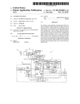
FIG. 1 is a block diagram of a system according to various
determined normalized insulation resistance value and one or 65 embodiments of the disclosed subject matter.
more of the previously determined insulation resistance val
ues, an amount of operational time of the electric motor until
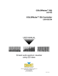
FIG. 2 is a block diagram of an apparatus according to
various embodiments of the disclosed subject matter.
US 8,427,192 B2
6
5
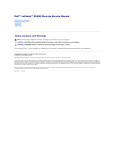
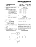
FIG. 3 shows a How chart of a method according to various
temperature measurement, a normalized resistance value for
the Windings is calculated. The calculation can be done auto
embodiments of the disclosed subject matter.
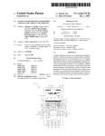
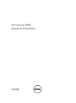
FIG. 4 is a screen shot of a ?rst tab of a user interface
matically upon input of the aforementioned resistance and
according to various embodiments of the disclosed subject
temperature values. The Winding resistance measurement can
be normalized to a common temperature and electronically
displayed in a resistance (e.g., in MOhms MQ) versus time
(e.g., t in months, quarters, seasons, years, or combination
thereof) graph including one or more previously normalized
matter.
FIG. 5 is a screen shot of a second tab of a user interface
according to various embodiments of the disclosed subject
matter.
FIG. 6 is a screen shot of a third tab of a user interface
Winding resistance values from previous Winding resistance
and temperature measurements. The determined normalized
or corrected Winding resistance value also can be stored and/
or compared to a predetermined value in order to diagnose a
characteristic of the electric motor. The temperature can be
according to various embodiments of the disclosed subject
matter.
FIG. 7 is a screen shot of a fourth tab of a user interface
according to various embodiments of the disclosed subject
normalized to a predetermined temperature, such as a tem
matter.
FIG. 8 is a screen shot of a ?fth tab of a user interface
perature of a previously taken temperature measurement
according to various embodiments of the disclosed subject
associated With the one or more Windings. Insulation resis
matter.
FIG. 9 is a screen shot of a sixth tab of a user interface
tance varies inversely, on an exponential basis With Winding
temperature. Thus, for the testing contemplated by the dis
closed subject matter, temperature normalization is important
according to various embodiments of the disclosed subject
20
matter.
In various embodiments, at least the previous Winding
5 populated With data according to various embodiments of
the disclosed subject matter.
resistance measurements Were previously stored in a memory
unit, for example. Based on information for or from the graph,
FIG. 10B is a screen shot of the third tab shoWn in FIG. 6
populated With data according to various embodiments of the
disclosed subject matter.
25
a characteristic or predicted or estimated characteristic of the
electric motor, such as remaining lifetime of the motor, pre
dicted or estimated time to motor failure or unsatisfactory
FIG. 10C is a screen shot of the fourth tab shoWn in FIG. 7
shoWing a resistance versus time “curve” plotted on a chart
and based on the data shoWn in the tabs of FIGS. 10A and
10B, according to various embodiments of the disclosed sub
ject matter.
to obtain reliable determinations at to normalized motor
Winding resistance.
FIG. 10A is a screen shot of the second tab shoWn in FIG.
30
DETAILED DESCRIPTION
operation thereof, and/or motor failure, can be identi?ed. As
alluded to above, a frequency of further electric motor testing
and analysis may be modi?ed or kept the same based infor
mation from or for the graph. For example, the frequency may
be increased (i.e., the time until the next test may be decreased
as compared to the time betWeen the tWo previous tests).
Optionally, in various embodiments, normalized humidity
In general, various embodiments of the disclosed subject
matter include determining and storing normalized electric
motor Winding resistance values over an extended period of
time in order to identify a characteristic or soon-to-be char
acteristic of the electric motor, such as remaining lifetime of
the motor, predicted or estimated time to motor failure or
35
Turning noW to the ?gures, FIG. 1 is a block diagram of a
40
unsatisfactory operation thereof, and/or motor failure. Such
information may be used as an indicator for replacing or
refurbishing the electric motor, or as an indicator forperform
ing preventative maintenance on the electric motor. Inciden
tally, the disclosed subject matter can be implemented for any
suitable electric motor, such as synchronous machines, induc
tion machines, and dc machines. The normalized electric
system 100 according to various embodiments of the dis
closed subject matter.
System 100 can be comprised ofa processing element 110,
a storage element 120, a display element 130, a resistance
measuring element 140, and a temperature measuring ele
ment 150. Not explicitly shoWn in FIG. 1, processing element
110 also may include on-board storage or memory, such as
45
memory for processing and storing computer programs for
50
execution. Optionally, system 100 may include a humidity or
moisture measuring element 160.An electric motor under test
(i.e., for taking a resistance measurement and other measure
ments), is not shoWn in FIG. 1. In various embodiments, the
motor under test Will be disconnected from its normal poWer
motor Winding resistance values may be taken once per rela
tively long periods of time, such as every month, every quar
ter, every season, or every year. Embodiments of the disclosed
data associated With the motor may be used to determine the
normalized Winding resistance values.
subject matter do not contemplate determining Winding resis
supply and discharged.
tance values (including normalized values) at shorter time
intervals, such as every second, minute, hour, day, or Week.
a resistance measurement of one or more electric motor Wind
Generally, system 100 can operate to take, read, or receive
The time period betWeen determining normalized Winding
resistance values may change based on analysis of determin
ing Winding resistance values. Such determination at to
ings (either stator or rotor Windings), such as insulation Wind
55
element 140 can be used to take, measure, or receive the
resistance of the electric motor Windings. Resistance measur
ing element 140 can be any suitable resistance measuring
changing time period for determining normalized resistance
values may be electronically calculated and the results of the
calculation displayed. Furthermore, embodiments of the dis
closed subject matter store or record the normalized electric
motor Winding resistance values in correlation to the date in
Which the values Were determined.
Various embodiments of the disclosed subject matter can
60
include measuring electric motor Winding resistance and
motor temperature. In various embodiments, these tWo mea
surements are performed at or about the same time. Based on
the resistance measurement or measurements as Well as the
ing resistance. In various embodiments, resistance measuring
65
system, apparatus, or device. For example, in various embodi
ments, resistance measuring element 140 is a single or spot
megohm/megaohm reading or measurement system, appara
tus, or device, such as a megaohm meter. Though FIG. 1
shoWs an arroW connecting resistance measuring element 140
With processing element 110, these tWo elements are not
necessarily physically connected (e.g., by electrical Wiring).
For example, in various embodiments, resistance measuring
element 140 can be a separate resistance measuring element
US 8,427,192 B2
7
8
from the processing element and data or information from the
using other respective devices thus have been used to obtain
resistance measuring element 140 can be entered manually by
a user of the processing element, for example. Alternatively
these readings and a technician or user inputs the data from
the readings into the respective ?elds in the user interface.
Furthermore, as Will be discussed With reference to apparatus
200 in FIG. 2, the functionality of at least elements 140 and
or optionally, data or information from the resistance mea
suring element 140 can be transmitted Wirelessly from the
resistance measuring element 140 to the processing element
150, and, optionally element 160, canbe part of one apparatus
110.
System 100 also can operate to take, read, or receive a
temperature measurement associated With electric motor. The
temperature measurement can be taken at any suitable loca
or device 200.
Though FIG. 1 shoWs only measuring or “input” elements
140, 150, and 160, processor 110 can receive other inputs. In
various embodiments, data inputs shoWn in the exemplary
tion and by any suitable means. For example, if the electric
motor has been at rest for a predetermined period of time, it
may be assumed that the Windings at are at ambient tempera
user interface of FIGS. 4 through 10 may be further inputted.
For example, the folloWing information may be added: name
plate data, year installed or last rehabbed, miscellaneous
notes on each motor; data of measurement, measured insula
tion resistance value, measured temperature, etc. In various
embodiments, some of the data may be manually entered,
ture of the interior or exterior of the Windings or motor. Thus,
in various embodiments, the temperature measurement is an
ambient temperature measurement of the electric motor and
may be representative of the temperature of one or more of the
electric motor Windings. In various embodiments, tempera
ture measuring element 150 is operative to take, read, or
receive a temperature measurement. Temperature measuring
such as year of motor installation and date of measurement,
and some data may be received electronically, such as mea
20
element 150 can be any suitable element for taking a tem
perature, ambient or otherWise, of an electric motor under
test, such as a thermometer, an infrared thermometer, etc.
Though FIG. 1 shoWs an arroW connecting temperature mea
suring element 150 With processing element 110, these tWo
elements are not necessarily physically connected (e.g., by an
25
Processing element 110 can be, for example, a computer,
perature measuring element from the processing element and
such as laptop or a desktop, a hand-held device, such as a
30
personal digital assistant (“PDA”) or cell phone, a micropro
cessor, a microcontroller, a computeriZed processor, etc. Pro
element, for example. Alternatively or optionally, data or
cessing element 110 can receive inputs, such as those dis
cussed above. For example, processing element 110 may
receive data representing a temperature measurement of the
information from the temperature measuring element 150 can
be transmitted Wirelessly from the temperature measuring
element 150 to the processing element 110.
Optionally, in various embodiments, system 100 also can
value readings may be manually entered via a user interface,
Whereas in other embodiments resistance value readings can
be electronically received and input. The inputs are not lim
ited to those shoWn in the exemplary user interface of FIGS.
4 through 10, and any suitable inputs or data may be input for
motor testing and analysis.
electrical Wiring). For example, in various embodiments,
temperature measuring element 150 can be a separate tem
data or information from the temperature measuring element
150 can be entered manually by a user of the processing
sured insulation resistance value, measured temperature, and/
or measured humidity. Any suitable combination of inputs
may be provided. Thus, in various embodiments, resistance
35
electric motor and automatically correct or normaliZe the data
to a common temperature, such as forty degrees Celsius or a
operate to take, read, or receive a humidity or moisture mea
previously other normaliZed temperature value based on a
surement associated With electric motor. Humidity measuring
40
previously measured and recorded temperature (e. g., the tem
perature of the motor the last time it Was tested). Processing
element 110 also may receive data representing a Winding
45
resistance measurement and determine a normaliZed Winding
resistance value based on the normaliZed temperature value
and the received Winding resistance measurement data, so
that so that Winding resistance value trending over time can be
tracked and analyZed at a constant relative temperature.
element 160 can take, read, or receive a humidity measure
ment. One example of a humidity measuring element 160
Would be Where the electric motor under test is in an air
conditioned room and a user or technician enters Zero or a
very loW humidity value into a user interface. The humidity
measuring element 160 according to various embodiments of
the disclosed subject matter is not limited to this example,
hoWever, and the humidity may be normaliZed based on an
Optionally, in various embodiments, processing element 110
algorithm executed by processing element 110. Though FIG.
also may receive data representing a humidity or moisture
1 shoWs an arroW connecting humidity measuring element
160 With processing element 110, these tWo elements are not
associated With the electric motor, such as a humidity or
moisture content in the vicinity or general local area or space
necessarily physically connected (e.g., by an electrical Wir
ing). For example, in various embodiments, humidity mea
50
suring element 160 can be a separate temperature measuring
element from the processing element and data or information
from the humidity measuring element 160 can be entered
manually by a user of the processing element, for example.
received humidity or moisture data to a common humidity or
moisture value. Thus, optionally, the normaliZed humidity or
moisture data may be used to determine the corrected or
55
Alternatively or optionally, data or information from the
humidity measuring element 160 can be transmitted Wire
Processing element 110 can cause some or all of the nor
memory. Storage of such data may be used for comparison
With future testing results. For example, processing element
60
110 may send to storage element 120 normaliZed Wiring
resistance data values. In various embodiments, the storage
normaliZed Winding resistance values are from sequential
individual tests of the Winding resistance of the electric motor
65
may send to display element 130 normaliZed Wiring resis
tance data for output thereon. In various embodiments, the
normaliZed Wiring resistance data may be plotted on a graph
being three separate elements, in various embodiments, one
input interface can be provided to receive data representative
of resistance and temperature, and optionally humidity. For
over an extended period of time. Processing element 110 also
example, the input interface can be a user interface, such as a
graphical user interface or touch screen capable of receiving
user input. So the aforementioned elements in this case Would
be three different input ?elds of the interface. Measurements
normaliZed Winding resistance value.
maliZed data to be stored, either in on-board or off board
lessly from the humidity measuring element 160 to the pro
cessing element 110.
Though elements 140, 150, and 160 are shoWn in FIG. 1 as
of the electric motor. Optionally, in various embodiments, the
processing element 110 may correct or normaliZe the
US 8,427,192 B2
10
of normalized Wiring resistance versus time. In various
as the information shoWn in the user interface of FIGS. 4
embodiments, the most recently determined normalized Wir
ing resistance value may be plotted With previously deter
mined normalized Wiring resistance values retrieved from
storage element 120. In various embodiments, the processing
through 10. In various embodiments, display element 130 can
have a graphing capability or functionality, Whereby it can
output a resistance versus time curve based on historical and
current normalized electric motor Winding resistance read
element 110 can automatically determine When to refurbish
or replace the electric motor based data for or from the plot of
normalized resistance values versus time. Alternatively or
optionally, the processing element 110 can predict at least one
of electric motor failure and a point in time at Which the
ings. Processing element 110 can interpret resistance and
time data for or of the graphical display to determine a con
dition of the motor Windings. Data also may be entered by
display element 130, for example, if the display element has
touchscreen capabilities. Furthermore, not explicitly shoWn
electric motor Will not operate satisfactorily. Optionally, in
various embodiments, processing element 110 can determine
a slope of the most recently determined Winding resistance
value and at least the second most recently determined Wind
ing resistance value. Based on the determined slope, the pro
cessing element 110 may determine that the motor has failed,
Will soon fail (including estimating a date of predicted fail
ure), or is operating unsatisfactorily. Thus, processor 110 may
cause an indication, by Way of display element 130, that the
electric motor has failed, Will fail, is operating unsatisfacto
in FIG. 1, a “manual” user interface may be provided to enter
data, such as a computer keyboard, a mouse, a keypad, etc.
FIG. 2 shoWs an apparatus 200 according to various
embodiments of the disclosed subject matter. Apparatus 200
is similar to system 100 in functionality. That is to say, in
various embodiments, apparatus 200 may be able to perform
all of the functions of the individual elements 110, 120, 130,
140, 150, and 160 ofsystem 100. For example, apparatus 200
20
rily, an estimated date of motor failure, or that the electric
motor needs to be refurbished or replaced. Optionally or
Motor resistance portion 240 can either measure motor resis
alternatively, in various embodiments, processing element
tance (essentially a built-in spot or single Megohm/Megaohm
110 can make a comparison of the determined corrected
Winding resistance value With a predetermined Winding resis
25
or by Way of a user manual input via a user interface. Simi
larly, motor temperature portion 250 and humidity portion
30
sor 110 may cause an indication, by Way of display element
130, that the electric motor has failed, Will fail, is operating
unsatisfactorily, an estimated date of motor failure, or that the
electric motor needs to be refurbished or replaced. In various
embodiments, processing element 110 may calculate and out
put on display element 130 a “neW” time interval for retesting
(i.e., for the next test) the Winding resistance of the electric
motor. For example, the processing element may decrease the
35
embodiments of the disclosed subject matter. The method 300
and variations thereof may be readily implemented in a com
40
predetermined Winding resistance value.
puter program product comprised of a computer-readable
storage medium having stored thereon softWare instructions
that, When executed by a processor, cause the processor to
perform operations as described herein and as appreciated to
those skilled in the computer arts.
Storage element 120 can be any suitable storage element,
such as a database in the form of a non-volatile memory
45
storage element 120 being outside processing element 110, in
various embodiments it can be located internal to processing
element 110. Furthermore, though shoWn as a single unit in
FIG. 1, storage element 120 may be a plurality of individual
storage units, such as different locations in one storage unit or
above for system 100 and Will not be described again. Not
explicitly shoWn, apparatus 200 also may have a user inter
face, such as a touchscreen or keypad, or combination thereof.
FIG. 3 is a How chart of a method 300 according to various
mined corrected Winding resistance value is at or beloW the
device, such as EEPROM or RAM. Though FIG. 1 shoWs
260 can either measure motor temperature and humidity,
respectively, or receive data representative of a measured
motor temperature and humidity. Item 210 is a processor,
item 220 is a storage element, and item 230 is a display
element. These items are substantially the same as described
time for a next Winding resistance measurement based on the
determined slope and/or Whether the most recently deter
device) or receive data representative of a measured motor
Winding resistance value, such as by Way of a Wireless or
Wired signal from a spot or single Megohm/Megaohm device
tance value. For example, if the determined corrected Wind
ing resistance value is at or beloW the predetermined Winding
resistance value, processor 110 may determine that the motor
has failed, Will soon fail (including estimating a date of pre
dicted failure), or is operating unsatisfactorily. Thus, proces
may be a hand-held, portable electronic apparatus a techni
cian can use for periodic electric motor testing and analysis.
50
Method 300 can start at S301 and proceed to S302.
At S302, electric motor data can be received for a motor
under test or to be tested. In various embodiments, received
data can include data representative of insulation resistance of
Windings of the electric motor and data representative of a
temperature associated With the Windings. In various embodi
multiple individual storage devices, Wherein each unit or
ments, the temperature is taken at or around a time as that of
device stores information for one particular electric motor or
a measurement of insulation resistance of Windings of the
motor. Optionally, received data can include data representa
tive of a humidity associated With the electric motor at the
time of taking the measurement of insulation resistance of
Windings of the motor. Received data also can include a time
one characteristic of each of the electric motors. Thus, storage
element 120 can storage a variety of information and data for
a particular motor, as Well as a variety of information for a 55
number of particular motors. For example, data shoWn in the
user interface of FIGS. 4 through 10 may be stored in storage
element 120, such as normalized Winding resistance data.
(e.g., the date) of taking the measurement of insulation resis
by display element 130 and/or used by processing element
tance of Windings of the motor. Received data also can
include data shoWn in the user interface of FIGS. 4 through
10.
S304 can include normalizing the temperature data to a
common temperature and normalizing or correcting the data
110 for further calculations based on “neW” measurements.
representative of the measured insulation resistance value
Data stored in storage element 120 for any electric motor
having been previously tested and data recorded With system
60
1 00 may be retrieved so that this information can be displayed
Display element 130 canbe any suitable electronic display,
such as a computer monitor, a touchscreen, LED, or LCD
display on a hand-held device, etc. Display element 130 can
display electric motor testing and analysis information, such
65
based on the normalized temperature. Optionally, if a humid
ity data is received, this data also may be normalized to a
common humidity. In various embodiments, the normaliza
tion can be done automatically and electronically.
US 8,427,192 B2
11
12
At S306, select normalized data can be stored in a storage
medium. Unless this is the ?rst time a motor has been tested,
been presented by Way of example only. Numerous modi?
cations and other embodiments (e. g., combinations, rear
rangements, etc.) are Within the scope of one of ordinary skill
in the art and are contemplated as falling Within the scope of
the disclosed subject matter and any equivalent thereto. It can
the storage medium should have stored therein previous
select normalized data. Select normaliZed data to be stored in
a storage medium can include the determined normaliZed
be appreciated that variations to the present disclosed subject
matter Would be readily apparent to those skilled in the art,
and the present disclosed subject matter is intended to include
insulation resistance value(s). Optionally, normaliZed tem
perature values can also be stored. In various embodiments,
data may have been previously or later stored, such as the
information shoWn in the exemplary user interface shoWn in
FIGS. 4 through 10. In various embodiments, the storing can
those alternatives. Further, since numerous modi?cations Will
readily occur to those skilled in the art, it is not desired to limit
the disclosed subject matter to the exact construction and
be done automatically.
operation illustrated and described, and accordingly, all suit
able modi?cations and equivalents may be resorted to, falling
S308 can include comparing the determined normaliZed
Winding resistance. In various embodiments, the determining
Within the scope of the disclosed subject matter.
It should be appreciated that any steps described above
may be repeated in Whole or in part in order to perform a
contemplated electric motor testing and/ or analysis task. Fur
normaliZed Winding resistance can be compared With one or
more previously determining normaliZed Winding resistance
values.
For example, the normaliZed Winding resistance values
(current and previous) can be plotted and displayed in a
ther, it should be appreciated that the steps mentioned above
resistance versus time graph. A comparison betWeen the cur
may be performed on a single or distributed processor. Also,
rent normaliZed Winding resistance value and one or more 20
the processes, elements, components, modules, and units
described in the various ?gures of the embodiments above
previous values can be made to determine a slope (e.g.,
declining slope) for the normaliZed Winding resistance val
ues. In various embodiments, the slope determination can be
done electronically based on data for the graph or of the
graph. The determined slope can be compared With one or
may be distributed across multiple computers or systems or
may be co-located in a single processor or system.
Embodiments of the method, system, apparatus, and com
25
puter program product (i.e., softWare) for electric motor test
ing and analysis, may be implemented on a general-purpose
computer, a special-purpose computer, a programmed micro
processor or microcontroller and peripheral integrated circuit
element, an ASIC or other integrated circuit, a digital signal
30
processor, a hardWired electronic or logic circuit such as a
more predetermined values. For example, if the slope of
decline exceeds a predetermined slope value, the time period
for a next resistance test may be shortened, Whereas if the
slope of decline does not exceed the predetermined slope
value, the time period for the next resistance test may be kept
the same as a previous time period. Optionally, if the slope of
decline exceeds another predetermined value, it can indicate
that the motor has failed, or needs refurbishing or replacing.
discrete element circuit, a programmed logic device such as a
PLD, PLA, FPGA, PAL, or the like. In general, any process
capable of implementing the functions or steps described
Optionally or alternatively, the presently determining Wind
ing resistance value may be compared to a predetermined
value.
35
senting data.
Furthermore, embodiments of the disclosed method, sys
tem, apparatus, and computer program product for electric
Based on the comparison result, a characteristic or pre
dicted or estimated characteristic of the electric motor, such
as remaining lifetime of the motor, predicted or estimated
time to motor failure or unsatisfactory operation thereof, and/
motor testing and analysis may be readily implemented, fully
40
or motor failure, can be identi?ed or determined. For
example, based on the data of or for the graph, an amount of
operational time of the electric motor until failure or unsatis
or partially, in softWare using, for example, object or object
oriented softWare development environments that provide
portable source code that can be used on a variety of computer
platforms. Alternatively, embodiments of the disclosed
method, system, and computer program product for electric
factory operation thereof may be estimated.
At S310 information is outputted based on the results of the
herein can be used to implement embodiments of the method,
system, or computer program product for providing or pre
45
motor testing and analysis can be implemented partially or
fully in hardWare using, for example, standard logic circuits
comparison. For example, an electronic display may display
a time for the next determination of normaliZed insulation
or a VLSI design. Other hardWare or softWare can be used to
resistance, such as remaining lifetime of the motor, predicted
implement embodiments depending on the speed and/ or e?i
ciency requirements of the systems, the particular function,
or estimated time to motor failure or unsatisfactory operation
thereof, and/or motor failure.
At S312, the method can end, or, if further long-term,
periodic testing is to occur, the method 300 may return to
S301 and repeat the process. As indicated earlier, generally
the process Will not repeat until one month, a quarter, six
50
and/or a particular softWare or hardWare system, micropro
cessor, or microcomputer system being utiliZed. Embodi
ments of the method, system, apparatus, and computer pro
gram product for electric motor testing and analysis can be
months, or one year after the most recent pass through the
55
or later developed systems or structures, devices and/ or soft
How chart.
FIGS. 4 through 10 an exemplary user interface With vari
ous data ?elds. The data ?elds may be populated by any
suitable means, such as automatically and electronically by a
processing element, by a user’s manual input, or a combina
tion thereof. FIGS. 10A through 10C shoWn an example of
output results based on data input to the system. The data
?elds are in noW Way limited to those shoWn in this example
implemented in hardWare and/or softWare using any knoWn
Ware by those of ordinary skill in the applicable art from the
functional description provided herein and With a general
basic knoWledge of the computer arts.
Incidentally, the folloWing documents are hereby incorpo
60
tice for Testing Insulation Resistance of Rotating Machinery;
ASTM D257-2009, Standard Test Methods for DC Resis
tance for Conductance of Insulating Materials; EASA, 2001,
user interface.
Having noW described embodiments of the disclosed sub
ject matter, it should be apparent to those skilled in the art that
the foregoing is merely illustrative and not limiting, having
rated by reference in their entireties: US. Pat. No. 7,127,373;
IEEE Standard 43-2000 (R2006), IEEE Recommended Prac
65
HoW to Get the Most From Your Electric Motors; FLUKE,
2007, Insulation Resistance Testing Application Note; MEG
GER, 2006, A Stitch in Time; CEORDR 110-2-42, 1992
US 8,427,192 B2
13
14
Motor Windings at Navigations and Lake Facilities; and Insu
tance value is one year and the decreased time interval is from
six months to one month, in one month increments.
lation System Testing, Presented by Don ShaW, Company
PdMA Corporation, Product Development Department.
The invention claimed is:
5. The method of claim 1, further comprising:
receiving as a third input, data representative of a humidity
5
1. A computerized method of modifying the frequency of
testing an electric motor, comprising:
of the insulation resistance of the electric motor Wind
ings; and
automatically and electronically normalizing the data rep
receiving as a ?rst input, data representative of insulation
resistance of Windings of the electric motor;
receiving as a second input, data representative of a tem
perature associated With the Windings during a measur
ing of the insulation resistance of the electric motor
in the vicinity of the electric motor during the measuring
10
resentative of the humidity,
Wherein said determining the normalized insulation resis
tance value of the electric motor Windings further
includes applying the normalized humidity data.
Windings;
resentative of the temperature associated With the Wind
6. The method of claim 1, further comprising performing a
Single or Spot Megohm/Megaohm Reading method to mea
sure the insulation resistance of the Windings of the electric
ings based on a common temperature, the common tem
motor.
automatically and electronically normalizing the data rep
perature being forty degrees Celsius;
7. The method of claim 1, Wherein the ?rst and second data
are input electronically.
8. The method of claim 1, Wherein the ?rst data is input
determining a normalized insulation resistance value of the
electric motor Windings by applying the normalized
temperature data to the data of the ?rst input, Which is
representative of the insulation resistance of the Wind
20
ings;
automatically storing in a nonvolatile storage medium the
making the next determination of a normalized insulation
resistance value of the electric motor;
normalized insulation resistance value of the electric
motor Windings;
electronically plotting and displaying the determined nor
25
electronically plotting and displaying said determined next
30
normalized insulation resistance value on the resistance
versus time graph; and
electronically determining a slope of decline of the insula
storage medium;
electronically determining a slope of decline of the insula
tion resistance of the Windings over time by comparing
the previously determined normalized insulation resis
automatically storing in the nonvolatile storage medium
said next determination of normalized insulation resis
tance value of the electric motor Windings;
malized insulation resistance value on a resistance ver
sus time graph, the graph including a previously deter
mined normalized insulation resistance value, the
previously determined normalized insulation resistance
value having been previously stored in the nonvolatile
electronically via a ?rst electronic device and the second data
is input electronically via a second electronic device.
9. The method of claim 1, further comprising:
tion resistance of the windings over time based on said
determined next normalized insulation resistance value.
10. A system for testing an electric motor, the system
35
comprising:
tance value With the determined normalized insulation
means for measuring a Winding resistance of the electric
resistance value;
comparing the slope of decline With a ?rst predetermined
slope value stored in the nonvolatile storage medium;
if the slope of decline exceeds the ?rst predetermined slope
means for measuring a temperature of the Windings of the
electric motor;
means for receiving as a ?rst input data representing the
motor;
40
measured Winding resistance;
value, decreasing a time interval until the next determi
nation of a normalized insulation resistance value of the
means for receiving as a second input data representing the
electric motor, as compared to a time interval betWeen a
time of said previously determined normalized insula
tion resistance value and a time of said determined nor
45
malized insulation resistance value;
if the slope of decline does not exceed the ?rst predeter
mined slope value, keeping same the time interval until
means for storing a previously measured temperature
value, the previously measured temperature value being
obtained at a time of taking a previous measurement of
the next determination of a normalized insulation resis
tance value of the electric motor; and
electronically outputting a time for the next determination
of normalized insulation resistance.
50
55
3. The method of claim 1, further comprising:
comparing the slope of decline With a second predeter
mined slope value stored in the nonvolatile storage
medium; and
refurbishing or replacing the existing motor if the slope of
decline exceeds the second predetermined slope value.
4. The method of claim 1, further comprising performing
the next determination of a normalized insulation resistance
value of the electric motor based on said decreased time
interval, Wherein the time interval betWeen a time of said
previously determined normalized insulation resistance value
and a time of said determined normalized insulation resis
the Winding resistance of the electric motor;
means for automatically correcting the data representative
of the temperature of the Windings based on the previ
ously measured temperature value;
2. The method of claim 1, further comprising projecting
time of failure of the electric motor based on the slope of
decline.
measured temperature of the Windings;
means for storing the ?rst input data;
means for storing the second input data;
means for determining a corrected Winding resistance
value of the electric motor Windings, the corrected Wind
ing resistance value being determined based on the cor
rected temperature data;
means for storing the determined corrected Winding resis
tance value of the electric motor Windings;
means for electronically displaying on a resistance versus
60
time graph the determined corrected Winding resistance
value of the electric motor Windings; and
means for determining When to refurbish or replace the
electric motor based on data from the resistance versus
time graph.
65
11. The system of claim 10, Wherein said means for storing
the ?rst input data, said means for storing the second input
data, said means for storing a previously measured tempera