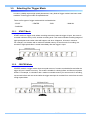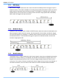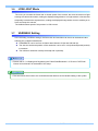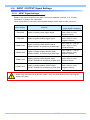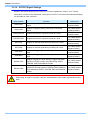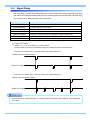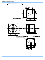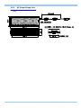
1
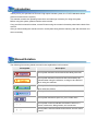
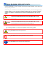
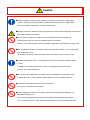
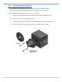
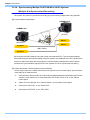
FASTCAM Mini UX100 WARNING This equipment has been tested and found to comply with the limits for a Class A digital device, pursuant to part 15 of the FCC Rules. These limits are designed to provide reasonable protection against harmful interference when the equipment is operated in a commercial environment. This equipment generates, uses, and can radiate radio frequency energy and, if not installed and used in accordance with the instruction manual, may cause harmful interference to radio communications. Operation of this equipment in a residential area is likely to cause harmful interference in which case the user will be required to correct the interference at his own expense. CAUTION: Any changes or modifications not expressly approved by the party responsible for compliance could void the user's authority to operate the equipment. The copyright of this manual is held by PHOTRON LIMITED. Product specifications and manual contents can change without advanced notification. This manual was created taking every possible measure to ensure the accuracy of its contents. However, if you find a section which is unclear, a mistake, or an omission, please contact PHOTRON LIMITED using the contact information provided at the end of the manual. PHOTRON LIMITED bears no responsibility for the results of using the product or from following the instructions in this manual. Introduction Thank you for your purchase of Photron’s high-speed camera system, the “FASTCAM MINI UX100” (referred to below as the system). This manual contains the operating instructions and warnings necessary for using the system. Before using the system, please read the entire manual. If any part of this manual is unclear, contact Photron using the contact information printed at the back of the manual. After you finish reading the manual, store it in a safe place along with the warranty card and refer back to it when necessary. Manual Notation The following icons and symbols are used in the explanations in this manual. Icon/Symbol Description This symbol indicates content that should always be read. This symbol indicates instructions that should always be followed when using the software, or things to be careful of when using the software. This symbol indicates supplementary items to be aware of when using the system. This symbol indicates the location of a reference. This symbol indicates a space for you to make notes. " [ This symbol is used to indicate the names of items on a " screen, references, dialog names, and connectors. ] This symbol is used to indicate menu names, and sub-menu names. Using the Manual This section explains the layout of the manual. Introduction The introduction explains the manual and safety precautions. Chapter. 1 Overview This chapter gives an overview of the system and an explanation of its features. Chapter. 2 Setup This chapter gives an overview of the components that make up the system. Please also refer to “Photron FASTCAM Viewer User’s Manual” for the details of operation by PC. Chapter. 3 Functions This chapter explains about the system’s functions. Chapter. 4 Reset of Gigabit Ethernet IF's IP address and Factory Default This chapter explains the procedure of resetting the system when the system does not work correctly. Chapter. 5 Product Specifications This chapter explains the system’s specifications. Chapter. 6 Warranty This chapter explains about the warranty. Chapter. 7 Contacting Photron This chapter lists the contact information to use when contacting Photron if the system malfunctions or if a portion of the manual is unclear. Using the System Safely and Correctly In order to prevent injury to yourself and others, and to prevent damage to property, carefully observe the following safety precautions. Photron has given its full attention to the safety of this system. However, the extent of damage and injury potentially caused by ignoring the content of the safety precautions and using the system incorrectly is explained next. Please pay careful attention to the content of the safety precautions when using the system. Warning Caution This symbol indicates actions that carry the risk that a person could receive a serious injury. This symbol indicates actions that carry the risk that a person could receive a moderate injury, or that damage to physical property might occur. The safety precautions to be observed are explained with the following symbols. This symbol indicates actions that require caution. This symbol indicates actions that are prohibited and must be avoided. This symbol indicates actions that must always be performed. Warning ■ Do not perform actions that will damage the AC cable or plug. (Do not damage the cable, modify it, use it near a heater, excessively bend, twist or pull on it, place heavy objects on it, or bundle it.) Using the cable when damaged can cause fire, electric shock, or a short circuit. ■ Do not use the system in a manner which will exceed the rating of the power outlet or wiring equipment used. Exceeding the power rating might cause a fire from excessive heat. ■ Do not insert metallic objects inside, or pour liquids such as water on, the system. Doing so can cause fire, electric shock, or malfunction from short circuit or heat. ■ Do not disassemble or modify the system. There are high voltages inside the system that can cause electric shock. ■ Do not plug in or unplug the power cord with wet hands. Doing so can cause electric shock. ■ This chapter lists the contact information to use when contacting Photron if the system malfunctions or if a portion of the manual is unclear. Not fully plugging in the power cable can cause fire from electric shock or heat. ■ When something is wrong with the system, unplug the power cable immediately. - When a foreign substance or liquid, such as metal or water, gets inside. - When the outer case is broken or damaged, such as from a fall. - When the system produces smoke, a strange smell, or strange sound. Using the system in these conditions might cause a fire or electric shock. Caution ■ Always unplug the system when cleaning it or when it is unused for a long period of time. Leaving or storing the system connected to the power source might cause fire from insulation deterioration or electrical discharge. ■Please consult us in advance when you perform an event by which laser light or direct rays fall on the image sensor surface. ■ Do not set the system in a location where the temperature gets unusually hot. The trunk and inside of a car can get especially hot in summer. Doing so can cause the outer case and internal components to deteriorate or cause a fire. ■ Do not place the system in a location prone to oily smoke or steam, or in a location with a lot of humidity or dust. Oil, moisture, and dust conduct electricity, which can cause a fire or electric shock. ■ Ambient temperature 0-40° C, humidity 85% RH or lower, maximum altitude 2,000m or lower. In addition, if exceeding these limits, use in a condensation-free environment. Doing so can cause malfunction. ■ Do not store the equipment in a location where the temperature goes below -20°C or higher than 60°C. Also, prevent condensation from forming during shipment ■ This device is for indoor use, do not use it outdoors. Do not use in a location that has dust. ■ When shipping, remove the connecting cable and use the original packaging or a dedicated carrying case. Do not ship the equipment in an environment where the temperature goes below -20°C or higher than 60°C. Also, prevent condensation from forming during shipment Cleaning of the Image Sensor Surface Electrostatic Discharge (ESD) events may cause immediate and unrecoverable damage to the image sensor. Please read the following instructions and take EXTREME CARE when cleaning the image sensor surface. ■ ALWAYS take appropriate anti-static precautions when cleaning or working near the Image sensor. ■ DO NOT use any form of cleaning equipment using electrostatic or ‘charged fiber’ technology. ■ Please discharge any electrostatic build up in your body by touching a grounded metallic Surface before working near the camera sensor. ■ Very gently, use only clean and dry air to remove dust from surface of the image sensor. ■ To remove stubborn contamination use the highest grade (e.g. VLSI grade) pure Isopropyl alcohol (IPA) with optical wipes of ‘clean room’ grade. ■ Extreme care must be taken! Gently wipe across the sensor in a single action. (DO NOT rub to avoid abrasive damage to delicate optical coatings on the glass surface.) Table of Contents Chapter. 1 Overview 1 1.1. 1.2. Product Overview and Features .............................................................................. 2 About the System’s Components and Accessories ................................................. 3 1.2.1. Components ................................................................................................ 3 1.2.2. Accessories/Options ................................................................................... 5 1.2.3. Type ............................................................................................................ 6 1.3. Part Names .............................................................................................................. 7 1.3.1. Camera Body .............................................................................................. 7 1.3.2. Camera Body Part Names .......................................................................... 8 1.3.3. Status Display LEDs on the Rear of the Camera Body .............................. 9 1.3.4. Interchangeable Lens Mounts................................................................... 11 Chapter. 2 Setup 13 2.1. Connecting the system .......................................................................................... 14 2.1.1. Connection ................................................................................................ 14 2.1.2. Connecting the AC Power Supply ............................................................. 15 2.2. Connecting the Gigabit Ethernet Interface to a PC ............................................... 16 2.2.1. Connecting a PC ....................................................................................... 17 2.3. Installing PFV ......................................................................................................... 18 2.4. PC Setup ................................................................................................................ 21 2.4.1. IP address setup for PC ............................................................................ 21 2.4.2. Windows Firewall Setup............................................................................ 23 2.4.3. Connections of PC and multiple systems ................................................. 25 Chapter. 3 3.1. 3.2. 3.3. 3.4. 3.5. Functions 27 What PFV Does ..................................................................................................... 28 Selecting the Frame Rate ...................................................................................... 29 Selecting the Resolution ........................................................................................ 29 Selecting the Shutter Speed .................................................................................. 30 Selecting the Trigger Mode .................................................................................... 31 3.5.1. START Mode ............................................................................................. 31 3.5.2. CENTER Mode ......................................................................................... 31 3.5.3. END Mode................................................................................................. 32 3.5.4. MANUAL Mode ......................................................................................... 32 3.5.5. RANDOM Mode ........................................................................................ 32 3.6. LOW LIGHT Mode ................................................................................................. 33 3.7. VARIABLE Setting ................................................................................................. 33 3.8. White Balance Adjustment (Color Models Only) .................................................... 34 3.8.1. Using Preset White Balance (Color Models Only) .................................... 34 3.8.2. Using User White Balance (Color Models Only) ....................................... 34 3.9. Color Enhancement Function (Color Models Only) ............................................... 35 3.10. Edge Enhancement Function ................................................................................ 35 3.11. Partition Memory & Record .................................................................................... 36 3.12. Input / Output Signal Types.................................................................................... 37 3.12.1. TRIG SW IN Connector ............................................................................ 38 3.12.2. IRIG IN Connector .................................................................................... 38 3.12.3. INPUT(1,2) Connector .............................................................................. 38 3.12.4. OUTPUT (1, 2) Connector ........................................................................ 39 3.13. Using External Triggers.......................................................................................... 40 3.13.1. Inputting an External Trigger Signal .......................................................... 40 3.13.2. Outputting External Trigger Signals .......................................................... 42 3.14. Using External Synchronization Signals ................................................................ 43 3.14.1. Inputting an External Synchronization Signal ........................................... 43 3.14.2. Outputting an External Synchronization Signal ........................................ 43 3.14.3. Synchronization with a variable frequency ............................................... 43 3.14.4. Synchronizing Multiple FASTCAM Mini UX100 Systems ......................... 44 (Multiple Unit Synchronized Recording) .................................................................. 44 3.14.5. Synchronizing the System with Other External Devices ........................... 46 (Frame Rate Synchronized Recording) ................................................................... 46 3.14.6. Synchronizing the System with Other Cameras ....................................... 48 (Mixed Device Synchronized Recording) ................................................................ 48 3.15. INPUT / OUTPUT Signal Settings ......................................................................... 49 3.15.1. INPUT Signal Settings .............................................................................. 49 3.15.2. OUTPUT Signal Settings .......................................................................... 50 3.16. Signal Delay ........................................................................................................... 51 3.17. Event Marker Function ........................................................................................... 52 3.18. IRIG Time Code (External Time Synchronization) ................................................. 53 3.19. Direct Trigger / Direct Start Mode .......................................................................... 54 Chapter. 4 4.1. Reset of Gigabit Ethernet IF's IP address and Factory Default 55 Reset of Gigabit Ethernet IF's IP address and Factory Default ............................. 56 4.1.1. Camera IP Address Initialization ............................................................... 56 4.1.2. Reset to the Factory Default ..................................................................... 56 Chapter. 5 Product Specifications 57 5.1. Specifications ......................................................................................................... 58 5.1.1. Product Specifications .............................................................................. 58 5.1.2. General Specifications .............................................................................. 59 5.1.3. AC / DC Adaptor ....................................................................................... 59 5.1.4. Options ...................................................................................................... 60 5.1.5. Frame Rate and Resolution ...................................................................... 62 5.1.6. Shutter Speed List .................................................................................... 66 5.1.7. Recordable Image Count/Resolution ........................................................ 67 5.1.8. Recordable Times/Resolution ................................................................... 68 5.2. Dimensions ............................................................................................................ 69 5.2.1. Camera Body ............................................................................................ 69 5.2.2. AC Power Supply Unit .............................................................................. 71 Chapter. 6 Warranty 72 6.1. About the Warranty ................................................................................................ 73 Chapter. 7 7.1. Contacting Photron 74 Contact Information................................................................................................ 75 Chapter. 1 Overview 1.1. Product Overview and Features 1.2. About the System’s Components and Accessories 1.3. Part Names 1 FASTCAM Mini UX100 Hardware Manual Chapter. 1 Overview 1.1. Product Overview and Features The FASTCAM Mini UX100 has superior recording performance (5,000fps at one million pixels, 800,000fps maximum) in a lightweight, compact design of only 1.5kg (3.3 lbs). The superior portability and recording performance is very useful for multiple purposes in research and development, design, production, and quality control, as well as numerous fields such as science, medicine, biology, aviation and space. The small body not only has in/out signal connectors for triggering and synchronization with other equipment , but also a Gigabit Ethernet connection that allows high speed data transportation and system control from a PC. The FASTCAM Mini UX100 fits various image analysis and image processing applications to simplify your workflow. Use this “state-of-the-art technology in a small body” for any dynamic image measurement purpose. FASTCAM Mini UX100 2 About the System’s Components and Accessories 1.2. 1.2.1. Components The system’s standard components are listed below. Remove the components from the packaging and check them. 1. Camera Body (with G type F mount) One 2. AC Power Supply Unit One 3. AC Cable (*Type is different in each country) One 4. C-mount One 3 FASTCAM Mini UX100 Hardware Manual Chapter. 1 Overview 5. 2m DC Extension Cable One 6. Gigabit Ethernet Interface Cable (LAN Cable) One 7. Hexagonal Wrench for Changing Lens Mounts (1.5 mm, 4 mm) One each 8. Lens Mount Cap (built into the camera body) One 9. FASTCAM Series Setup Disk (Driver/Application DVD) One 10. FASTCAM Mini UX100 Hardware Manual (this manual) One 11. Photron FASTCAM Viewer (PFV) User's Manual One 12. How to Make a Gigabit Ethernet Connection (Simple Procedure Manual) One 13. FASTCAM Mini UX100 FirstStepGuide One This system does not include a lens. 4 1.2.2. Accessories/Options The following options are available for the system. 1. Dedicated Carrying Case 2. DAQ option 3. Movie analysis software Lenses, lamps and other kinds of options are available. Please contact our sales representative or distributors. Please refer to “7.1. Contact Information”. 5 FASTCAM Mini UX100 Hardware Manual Chapter. 1 Overview 1.2.3. Type For the FASTCAM Mini UX100 system, there are monochrome and color versions, for each of these versions, there are 4 GB standard memory capacity type and 8 GB (or 16GB) high capacity type. When purchasing, it is possible to select from these models according to the application or your demands. The Types are listed below. Max. Frame Rate Sensor Type Color 800,000fps Monochrome Memory Type Name 4GB 8GB 16GB 4GB 8GB 16GB FASTCAM Mini UX100 type 800K - C - 4GB FASTCAM Mini UX100 type 800K - C - 8GB FASTCAM Mini UX100 type 800K - C - 16GB FASTCAM Mini UX100 type 800K - M - 4GB FASTCAM Mini UX100 type 800K - M - 8GB FASTCAM Mini UX100 type 800K - M - 16GB 6 Part Names 1.3. The system is composed of components including the camera body, AC power supply, and the "Photron FASTCAM Viewer" control software (referred to below as PFV). For each of the system components. - Do not expose to shock. - Do not use in an area where flammable gas or dust present is present. - Do not place in an unstable location such as on an unstable platform or an incline. - Do not disassemble or modify. - Do not expose to liquids such as water. - Do not subject to excessive force. 1.3.1. Camera Body The camera body contains IC memory for image recording and has been designed to be able to record high-speed images uncompressed. The back of the camera body is equipped the Gigabit Ethernet interface, which permits full camera control and data download possible via connection to a PC; the input/output connector, which allows external synchronization signals, trigger signals, IRIG time code. Apperance Rear FASTCAM Mini UX100 7 FASTCAM Mini UX100 Hardware Manual Chapter. 1 Overview 1.3.2. Camera Body Part Names FASTCAM Mini UX100 G type F Mount Front Front Status Indicator LEDs GIGABIT ETHER Gigabit Ethernet LAN Cable Connector SYNC IN ER PO W RESET SW IP address Reset Switch IF A NS TR ER K/ GG L IN TR I G IR I NC SY REC READY REC DE MO RESET 1000BASE-T POWER SW Power Switch POWER IRIG IN INPUT 1 ( DEF:SYNC IN ) INPUT 2 ( DEF:TRIG TTL IN ) I/O PORT I/O Port Connector DC22-32V 40VA Power Supply Connector DC22-32V TRIG SW IN Back 8 OUTPUT 2 OUTPUT 1 ( DEF:SYNC OUT ) ( DEF:TRIG TTL OUT ) 1.3.3. Status Display LEDs on the Rear of the Camera Body There are a number of LEDs on the rear of the system's camera body. These LEDs indicate the status of the system. The function of each LED is explained here. POWER (Green) LED ON: Power On LED OFF: Power Off IF LINK/TRANS (Red) LED ON: The Gigabit Ethernet interface is connected LED FLASHING: Data is transferring LED OFF: The Gigabit Ethernet interface is not connected TRIGGER (Yellow) LED ON: A trigger signal is present (being input) (The LED will illuminate for 0.1 second when the trigger signal is input.) LED OFF: The trigger signal is not present IRIG (Green) LED ON: The IRIG signal is present (being input) LED OFF: The IRIG signal is not present SYNC MODE (Red) LED ON: In external synchronization mode (synchronized to an external signal) LED OFF: In internal synchronization mode (synchronized to the internal signal) SYNC IN (Yellow) LED ON: A synchronization signal is present (being input) LED OFF: A synchronization signal is not present REC READY (Yellow) LED ON: Ready to record LED FLASHING: ENDLESS recording (The REC (Red) LED is also flashing) LED OFF: Not ready to record REC (Red) LED ON: Ready to record (The case of “ENDLESS” recording mode) LED FLASHING: Recording LED OFF: Not recording 9 FASTCAM Mini UX100 Hardware Manual Chapter. 1 Overview Illumination/blinking in operational states During the Gigabit Ethernet interface initialization LEDs other than POWER (green) and IF LINK/TRANS (red) blink alternately from right to left and from left to right a number of times. When Fuctory Default is executed, LEDs other than POWER (green) and IF LINK/TRANS (red) fade out from right to left a number of times, then blink. For how to initialize the Gigabit Ethernet interface, and how to reset to Factory Default, refer to "4.1. Reset of Gigabit Ethernet IF's IP address and Factory Default ", page 56. 10 1.3.4. Interchangeable Lens Mounts The lens mount on the system can be changed according to the recording purpose. There are 2 types of interchangeable lens mounts: “G type F-mount”, “C-mount”. How to change the lens mount (G type F-mount → C-mount) 1. Remove the four M5 bolts with the hexagonal holes using the hexagonal wrench. 2. Remove the G type F-mount portion as a unit. 3. Install the C-mount unit using the bolts with hexagonal holes in the 90° diagonal holes. 4. After installation, always verify that the unit is not loose and does not rattle. C Mount G type F Mount (Standard) 11 FASTCAM Mini UX100 Hardware Manual Chapter. 1 Overview 12 Chapter. 2 Setup 2.1. Connecting the system 2.2. Connecting the Gigabit Ethernet Interface to a PC 2.3. Installing PFV 2.4. PC Setup 13 FASTCAM Mini UX100 Hardware Manual Chapter. 2 Setup 2.1. 2.1.1. Connecting the system Connection Status LEDs Gigabit Ethernet LAN cable connector Power on/off SW DC22-32V Power connector PC with PFV installed Rear panel Controller details LAN Cable (Gigabit Ethernet) Camera Body 2m DC Extention Cable AC Power Supply Unit AC Cable The FASTCAM camera supports 1000BASE-T (Gigabit Ethernet) only. If your PC supports 10BASE-T or 100BASE-T only, you need to install a 1000BASE-T interface board or use a switching hub that supports 10BASE-T, 100BASE-T and 1000BASE-T. 14 2.1.2. Connecting the AC Power Supply Connect the supplied AC power supply unit to the power supply. 1, 6 2 3 4 5 1. Confirm the Power SW is turned off. 2. Connect the2m DC Extension cable to the “DC22-32V” connector on the back of the camera body. 3. Connect the 2m DC Extension cable to AC power supply unit. 4. Connect the AC cable to the AC power supply unit. 5. Connect the AC cable to the power outlet. 6. Turn on the Power SW one the system. For the specification of the power supply which can be used, refer to “5.1.2. General Specifications”, page 59. Please use an AC cable with a ferrite core. 15 FASTCAM Mini UX100 Hardware Manual Chapter. 2 Setup 2.2. Connecting the Gigabit Ethernet Interface to a PC The system can have the operation of its functions performed from a PC using the Gigabit Ethernet interface.This section explains the required setup when connecting the system to a PC. To connect a PC to the system, connect the system to a commercially available 1000BASE-T-compatible interface board with a LAN cable. For the LAN cable, prepare a UTP or STP Cat 5e (enhanced category 5) or higher LAN cable. (UTP: Unshielded Twisted Pair, STP: Shielded Twisted Pair) The maximum cable length between the PC and the system is 100 m (compliant to the 1000BASE-T specification).. One PC can connect to a maximum of 64 Photron Gigabit Ethernet interface equipped cameras using a hub. When connecting multiple devices, connect through a switching hub that can connect at 1000BASE-T. The maximum length of the cable that connects the system (or PC) to the switching hub is also 100 m. For the setting method of IP address for camera system, refer to “2.4.1. IP address setup for PC”, page 21. For the setting method of control PC, refer to “Photron FASTCAM Viewer User's Manual”. Please refer to the [GigabitEthernet Interface Connection Tutorial Manual」 for detail instruction on PC connection setting. Photron recommends using an STP cable over long distances or in noisy locations. The system is only 1000BASE-T compatible. When using a PC compatible with only 10BASE-T or 100BASE-TX, the PC must be connected through a 10BASE-T, 100BASE-TX, and 1000BASE-T compatible switching hub. The system's factory default IP address is below: IP ADDRESS > GIGABIT ETHER 192.168.0.10 NETMASK > 255.255.255.0 GIGABIT ETHER GATEWAY ADDRESS > 0.0.0.0 PORT > 2000 (Fixed, not changeable) 16 2.2.1. Connecting a PC The system can have the operation of its functions performed from a PC using the Gigabit Ethernet interface. This section explains the required setup when connecting the system to a PC. Insert a LAN cable to “1000BASE-T” connector. A bundled LAN cable may be different from the cable in the picture. 17 FASTCAM Mini UX100 Hardware Manual Chapter. 2 Setup 2.3. Installing PFV This system is controlled by PFV. This section explains a software installation and its setup. 1. 2. Insert the PFV installation DVD in the DVD drive and open that drive form “Computer”. For a 32-bit version of Windows, open the "PFV Setup32" folder and double click "Setup.exe". For a 64-bit version of Windows, open the "PFV Setup64" folder and double click "Setup.exe". 18 3. The setup program starts and the dialog box below is displayed. Click the [Next] button. 4. The license agreement is displayed. Confirm the contents and click the [Yes] button. 19 FASTCAM Mini UX100 Hardware Manual Chapter. 2 Setup 5. Specify the installation location. The default setting for the installation location is “C:\Program Files\Photron\Photron FASTCAM Viewer 3”. When necessary, click the [Browse] button and change the installation location to your preferred location. After specifying the installation location, click the [Next] button. 6. The installation starts, when it is completed, the screen below is displayed. Click the [Finish] button. 20 2.4. PC Setup 2.4.1. IP address setup for PC This system is controlled by a PC via network. This section explains IP address setup for connecting the system and PC. 1. Open Start Menu, click “Control Panel” 2. Click “View network status and tasks”. If “View by:” is not “Category”, Click “Network and Sharing Center”. 3. 4. Click “Change adapter settings” at left side. Network devices on the PC are displayed. Right click “Local Area Connection”. Then click “Properties”. 21 FASTCAM Mini UX100 Hardware Manual Chapter. 2 Setup 5. “Local Area Connection Properties” window is opened. Double click “Internet Protocol Version 4 (TCP/IPv4)” 6. “Internet Protocol Version 4 (TCP/IPv4) Properties” window is opened. Check on “Use the following IP address:” radio button. Input IP address and Subnet mask as below, then close the window by clicking “OK”. IP address : 192 . 168 . 0. 1 Subnet mask : 255 . 255 . 255 . 0 22 2.4.2. Windows Firewall Setup Even if an IP address is set up, Windows Firewall blocks the connection. This section explains how to set up that PFV is allowed through Windows Firewall. 1. Open Start Menu and click “Control Panel”. 2. Click “System and Security”. Then click “Allow a program through Windows Firewall” 3. Click [Allow another program…] button. If the button is gray-out. Click [Change settings] before that. 23 FASTCAM Mini UX100 Hardware Manual Chapter. 2 Setup 4. Select the installed “PFV Ver.XXX”, then click [Add] button. 5. Click [OK] button and close the window. 24 2.4.3. Connections of PC and multiple systems The control software PFV can control multiple systems of SA series, Mini, MC2.1 and MH4-10K by connecting with one PC. Please do not set up conflicted IP addresses. 25 FASTCAM Mini UX100 Hardware Manual Chapter. 2 Setup 26 Chapter. 3 Functions 3.1. What PFV Does 3.2. Selecting the Frame Rate 3.3. Selecting the Resolution 3.4. Selecting the Shutter Speed 3.5. Selecting the Trigger Mode 3.6. LOW LIGHT Mode 3.7. VARIABLE Setting 3.8. White Balance Adjustment (Color Models Only) 3.9. Color Enhancement Function (Color Models Only) 3.10. Edge Enhancement Function 3.11. Partition Memory & Record 3.12. Input / Output Signal Types 3.13. Using External Triggers 3.14. Using External Synchronization Signals 3.15. INPUT / OUTPUT Signal Settings 3.16. Signal Delay 3.17. Event Marker Function 3.18. IRIG Time Code (External Time Synchronization) 3.19. Direct Trigger / Direct Start Mode 27 FASTCAM Mini UX100 Hardware Manual Chapter. 3 Functions 3.1. What PFV Does Operating this system requires connecting PC and the system, and the control software PFV. The following figure shows functions which PFV can do. Please refer to “Photron FASTCAM Viewer User’s Manual” for the details of operation. Control the high-speed camera with the PC Display the live image Set shot conditions Collective control of multiple cameras Set the trigger mode Shoot PFV Manual Chapter.2 PFV Manual Chapter.3 Playback of the camera’s recorded images Play the images recorded by the camera Select replay speed and number of frames PFV Manual Chapter.4 Saving recorded images Save recorded images to the PC Save as a specified file type Save a specified area or number of frames Add information to an image and save PFV Manual Chapter.5 Play saved data Play/resave data saved to the PC Read/simultaneous playback of multiple data PFV Manual Chapter.6 28 3.2. Selecting the Frame Rate Images can be recorded with the system from 50 fps to 4,000 fps using the full 1,280x1,024 pixel resolution of the image sensor. For frame rates higher than 4,000 fps, high-speed recording is achieved by limiting the read area of the image sensor. Please refer to “3.3 Setting and Registering the Frame Rate/Resolution” of “Photron FASTCAM Viewer User’s Manual” for the details of the setup. Even if a limited horizontal resolution is applied, Frame Rate cannot be increased. This specification is different from other systems. Please refer to “5.1.5. Frame Rate and Resolution” for available frame rate. 3.3. Selecting the Resolution The maximum resolution of the image sensor is 1,280 x 1,024: total 1,310,720 pixels. By reducing the resolution, images can be taken with even faster frame rates, or the recording duration can be extended accordingly. Please refer to “3.3 Setting and Registering the Frame Rate/Resolution” of “Photron FASTCAM Viewer User’s Manual” for the details of the setup. 29 FASTCAM Mini UX100 Hardware Manual Chapter. 3 Functions 3.4. Selecting the Shutter Speed The shutter speed (Exposure time) is independent of the frame rate, and it is possible to control the exposure time in the frame using the electric shutter. By making an exposure that is of a shorter period than the frame rate, high-speed objects can be photographed blur-free. The shortest setting value of shutter speed is 1/1,000,000 sec (approx 1 usec). Please refer to “3.4 Setting the Shutter Speed” of “Photron FASTCAM Viewer User’s Manual” for the details of the setup. A minimum exposure time depends on a set up frame rate. 50fps FrameRate ~ 160,000fps 200,000fps 256,000fps 512,000fps 800,000fps Limitation 1/frame ~ 1/256,000 sec are selectable 1/frame sec (3.76usec) is only available 1/frame sec (2.72usec) is only available 1/frame sec (1.78usec) is only available 1/frame sec (1usec) is only available 30 Selecting the Trigger Mode 3.5. In order to reliably capture high-speed phenomena, many kinds of trigger modes have been made available. These trigger modes are explained next. There are five types of trigger modes which are listed below. - START - CENTER - END - MANUAL - RANDOM 3.5.1. START Mode START mode is a trigger mode where recording starts the instant the trigger is input, the scene is recorded until the memory is full, and then recording ends. This mode is suitable for taking images of high-speed phenomena when what will happen, and when it happens, is known in advance. For example, in a situation with a maximum useable memory of two seconds of recording, two seconds of high-speed video is saved immediately after the trigger is input. 3.5.2. CENTER Mode CENTER mode is a trigger mode where an equal amount of content recorded before and after the trigger is input is saved to memory. This mode is suitable for viewing before and after an important instant. For example, in a situation with a maximum useable memory for two seconds of recording, one second before and one second after the trigger was input is recorded for a total of two seconds of high-speed video. 31 FASTCAM Mini UX100 Hardware Manual Chapter. 3 Functions 3.5.3. END Mode END mode is a trigger mode where the content recorded immediately before the trigger is input is saved to memory. This mode is suitable for recording a high-speed phenomenon where it is hard to predict when the important action will start and stop. For example, in a situation with a maximum useable memory for two seconds of recording, the two seconds of high-speed video immediately before when the trigger was input are saved. 3.5.4. MANUAL Mode MANUAL mode is a trigger mode, similar to CENTER mode, where the content recorded before and after the trigger is input is saved to memory, but the proportion of time before and after the trigger can be set as required. For example, in a situation with a maximum record time of two seconds, 0.5 seconds before and 1.5 seconds after the trigger is input are recorded and saved, a total of two seconds of high-speed video. 3.5.5. RANDOM Mode RANDOM mode is a trigger mode where each time a trigger is input only a predetermined number of frames are saved to memory. For example, this function is convenient for a subject which is an irregular and repeated phenomenon which can have a trigger output produced for each cycle or occurrence. The number of frames recorded each time the trigger is input can be set as desired, in one frame increments, from one frame to the maximum of all the recordable frames available. 32 LOW LIGHT Mode 3.6. The more you increase the frame rate or shutter speed of the camera, the more the amount of light entering the camera decreases, making the displayed image darker. Low light mode is a function that temporarily increases the exposure time, making the displayed image easier to see to enable you to focus and setup the camera. The default shutter speed of this product is 1/50 second. VARIABLE Setting 3.7. In the recording conditions settings, the frame rate and resolution can be set to the desired value following the conditions listed below. FRAMERATE can be set from 46 frame rates between 50 fps and 256,000 fps. The size and horizontal position of the resolution can be set in 128 (horizontal) and 8(vertical) increments. The minimum resolution is 640 (horizontal) and 8 (vertical). Please refer to “3.3 Setting and Registering the Frame Rate/Resolution” of “Photron FASTCAM Viewer User’s Manual” for the details of the setup. The area cannot be moved to the vertical/horizontal direction at the variable setting of the system. 33 FASTCAM Mini UX100 Hardware Manual Chapter. 3 Functions White Balance Adjustment (Color Models Only) 3.8. On digital video cameras, photographing white as pure white is described as "having the appropriate white balance." On the system's color models as well, in order to take images with the correct color representation, the white balance must be adjusted for the color temperature of the light source used. The intensity of each color, R, G, and B, can be adjusted on this system. By adjusting the balance of those three colors to match the light source used, the appropriate white balance can be achieved. Two methods are available for adjusting the white balance, preset and user-editable white balance. These methods are explained in this section. 3.8.1. Using Preset White Balance (Color Models Only) With the system, there are two types of white balance presets (5100K, 3100K) for use with common light sources. The suggested color temperature for these presets is listed below. 5100K (Daylight, Outdoors) 3100K (Halogen Light Source) 3.8.2. Using User White Balance (Color Models Only) User white balance can be set in order to achieve the most appropriate white balance for the light source used with the system and the conditions during recording. The values set here are stored in the camera body's internal memory as the user preset, and they can be loaded by selecting USER. There are also two methods for setting user white balance, AUTO USER and EDIT USER. Please refer to “3.8 Other Settings” of “Photron FASTCAM Viewer User’s Manual” for the details of the setup. 34 3.9. Color Enhancement Function (Color Models Only) Color models feature an image color enhancement setting. The image color enhancement level can be adjusted in five steps, including the OFF setting. Menu Display Contents OFF x0.5 (LEVEL1) x1 (LEVEL2) Turns the color enhancement mode off x1.5 (LEVEL3) x2 (LEVEL4) Sets x1.5 color enhancement Sets x0.5 color enhancement Sets x1 (default) color enhancement Sets x2 color enhancement Please refer to “3.8 Other Settings” of “Photron FASTCAM Viewer User’s Manual” for the details of the setup. 3.10. Edge Enhancement Function With the system's edge enhancement setting, you can enhance the edges in the recorded image in four steps, including the OFF setting. Menu Display OFF Contents Edge enhancement off. LEVEL1 Edge enhancement set to weak. LEVEL2 Edge enhancement set to medium. LEVEL3 Edge enhancement set to strong. Please refer to “3.8 Other Settings” of “Photron FASTCAM Viewer User’s Manual” for the details of the setup. 35 FASTCAM Mini UX100 Hardware Manual Chapter. 3 Functions 3.11. Partition Memory & Record The system contains internally 4 GB standard, or a maximum of 16 GB, of high-capacity memory for recording use. This recording memory can be partitioned and assigned to each recording. Memory is partitioned into equal sizes and a maximum of 64 partitions can be set. The partitioned sections are managed by ID numbers. Each section can be set with completely independent recording conditions, so this feature is convenient when taking consecutive recordings with changed conditions. Please refer to “3.8 Other Settings” of “Photron FASTCAM Viewer User’s Manual” for the details of the setup. 36 3.12. Input / Output Signal Types With the system, many signals can be input and output through the I/O connector. Signals that can be input and output from the I/O connector are listed below. A signal other than the specified signal must not be input to the various connectors. Use extreme caution as there is a risk of damage to both, the input device and the output device. Please refer to “3.8 Other Settings” of “Photron FASTCAM Viewer User’s Manual” for the details of the setup. 37 FASTCAM Mini UX100 Hardware Manual Chapter. 3 Functions The followings are I/O connectors and related signals. 3.12.1. TRIG SW IN Connector This trigger is input during the READY or ENDLESS recording state by contact between the BNC connector's shield and a center pin (switch closure). The center pin normally has voltage flowing through it. Use caution to avoiding contact with other pins. 3.12.2. IRIG IN Connector IRIG signal is input from other equipment. 3.12.3. INPUT(1,2) Connector The effect when a signal is input is described below, and can be optionally selected and set. The input voltage is 0V to +12V (H level +2.5V to +12V), positive or negative polarity, pulse width is 200 ns or greater. Default settings are INPUT1 connector is assigned “SYNC POS”, INPUT2 connector is assigned “TRIG POS”. SYNC POS/NEG TRIG POS/NEG Inputs a synchronization signal from another camera or other equipment. Inputs a TTL signal to control start/end of recording. The system’s status should be set READY or ENDLESS. READY POS/NEG Inputs a change recording ready status signal (READY ON/OFF). EVENT POS/NEG Inputs a signal for the event trigger. Please refer to”3.18 Event Marker Function” page 53 for the event trigger. When 2 or more these systems are synchronized, slave cameras’ external synchronization settings should be set “ON CAM” at PFV. 38 3.12.4. OUTPUT (1, 2) Connector These are also BNC connectors. The signals below can be changed and output from PFV. The output voltage is 0V to +5V, positive or negative polarity, pulse width can be changed. Default settings are OUTPUT1 connector is”SYNC POS”, OUTPUT2 is ”TRIG POS”. SYNC POS/NEG EXPOSE POS/NEG REC POS/NEG TRIG POS/NEG READY POS/NEG (POS: positive polarity, NEG: negative) Outputs a vertical synchronization signal. Outputs the camera's exposure period signal. * Outputs during both LIVE and recording. Outputs a signal during recording. Outputs the trigger signal the camera received. Outputs a signal that indicates the recording ready state. 39 FASTCAM Mini UX100 Hardware Manual Chapter. 3 Functions 3.13. Using External Triggers With the system, you can record by receiving various trigger signals matched to the recording application. The trigger signals that can be used on the system are explained here, along with a description of how to use them. 3.13.1. Inputting an External Trigger Signal The external trigger signals that can be used with the system and their input system are listed below. Connector Name (Input System) Menu Signal TRIG POS FET Input 0V - +12V (H level +2.5V to +12V), Positive Polarity TRIG NEG FET Input 0V - +12V (H level +2.5V to +12V), Negative Polarity INPUT TRIG SW IN None Contact signal When a trigger signal is input to INPUT connector, this item should be set to a signal type. Use caution not to input more than specified voltage or current to the INPUT trigger signal inputs as there is a risk of damage to the equipment. For the setting method of the signal inputted into INPUT, refer to “3.15.1. INPUT Signal Settings”, page 49. 40 INPUT, TRIG SW IN Circuit Diagram INPUT_1 INPUT_2 330ΩF 330ΩF TRIGGER_SW_IN INPUT_1 INPUT_2 41 FASTCAM Mini UX100 Hardware Manual Chapter. 3 Functions 3.13.2. Outputting External Trigger Signals With the system, you can externally output trigger signals. Output can also be optionally set from the OUTPUT connector. The chart below summarizes the output systems and the signals that can be output. Connector Name (Output System) Menu Setting Signal Type TRIG POS TTL, SW, SOFT, all TRIG pulse output CMOS (74ACT541 buffer) output, Positive Polarity. TRIG NEG TTL, SW, SOFT, all TRIG pulse output CMOS (74ACT541 buffer) output, Negative Polarity. OUTPUT 42 Delay Time For TRIG SW IN, approx. 20,4 usec. For INPUT, approx. POS: 220n sec. NEG: 228n sec 3.14. Using External Synchronization Signals An external synchronization mode to synchronize to an external signal is provided on the system. By using an external synchronization signal, recording can be conducted using multiple cameras to synchronize the timing of the shots or to also synchronize the shots with external measuring devices and lighting. The procedure and precautions for using the external synchronization signal are explained below. 3.14.1. Inputting an External Synchronization Signal An external synchronization signal can be input with the system. See the chart below for external synchronization input settings. Menu Display Contents Signal (Input Signal Conditions) OFF Sets external synchronization off, operates independently. (none) ON CAM POS Synchronizes to a positive polarity signal from Photron products. FET Input 0V - +12V (H level +2.5V to +12V), Positive Polarity ON CAM NEG Synchronizes to a negative polarity signal from Photron products. FET Input 0V - +12V (H level +2.5V to +12V), Negative Polarity ON OTHERS POS Synchronizes to a positive polarity signal from an external device (including other Photron products). FET Input 0V - +12V (H level +2.5V to +12V), Positive Polarity ON OTHERS NEG Synchronizes to a negative polarity signal from an external device (including other Photron products). FET Input 0V - +12V (H level +2.5V to +12V), Negative Polarity 3.14.2. Outputting an External Synchronization Signal The system can externally output a synchronization signal. Menu Display Contents Signal Type Delay Time SYNC POS Outputs a positive polarity vertical synchronization signal. CMOS (74ACT541 buffer) output, positive polarity Approx. 118nsec SYNC NEG Outputs a negative polarity vertical synchronization signal. CMOS (74ACT541 buffer) output, negative polarity Approx. 138nsec 3.14.3. Synchronization with a variable frequency When synchronizing with a varying input frequency signal, the frame rate and resolution specified before recording will be kept as a maximum value. 43 FASTCAM Mini UX100 Hardware Manual Chapter. 3 Functions 3.14.4. Synchronizing Multiple FASTCAM Mini UX100 Systems (Multiple Unit Synchronized Recording) The system can perform synchronized recording by synchronizing multiple units using external. Synchronization input/output CAMERA No.2 CAMERA No.1 (SLAVE) INPUT 1 (MASTER) INPUT 2 OUTPUT 1 (BNC Cable) OUTPUT 2 Synchronized recording settings using the system are made with PFV. The conceptual settings when performing synchronized recording using two systems are explained here. First, decide which camera to make the master camera (outputs the synchronization signal) and the slave camera (receives the synchronization signal) from the two systems to use for synchronized recording. Setting the Master Camera (Outputs Synchronization) Set the signal output for the master camera which will output the synchronization signal. Synchronization signal settings are made with PFV. 1. Verify that the camera mode is in LIVE mode (the image displayed is passed through from the camera). If the system is in a mode other than LIVE mode, check "Live" on the camera control panel. 2. Select I/O on the left tree from "Camera Option" on the camera control panel. 3. Ensure that “OUTPUT1” is set “SYNC POS”. 4. Ensure that “OUTPUT2” is set “TRIG POS”. 44 Setting the Slave Camera (Receives the Synchronization Signal) Next, set the synchronization signal input for the slave camera which will receive the synchronization signal supplied by the master camera. Synchronization signal settings are made with PFV. 1. Input a synchronization signal to the slave camera. Connect the master camera’s INPUT1 connector and the slave camera’s INPUT1 connector with a BNC cable. When a synchronization signal is input to INPUT1 connector, SYNC IN LED (yellow) on the slave camera’s back side lights. 2. Ensure the camera mode is “LIVE” (a live image is displayed). If the camera mode is set others, check on “LIVE” at the control panel. 3. Select “I/O” at “Camera Option” of the control panel. 4. Ensure “INPUT1” is set “SYNC POS”. 5. Ensure “INPUT2” is set “TRIG POS”. 6. Set “ON CAM POS” at “SYNC IN”. When a recording is started by pushing REC button on PFV, check on “No trigger input from PFV” at “Configuration > Record Option > Trigger input setting to slave camera”. If steps, 2 to 3 are completed when no synchronization signal is being input, the camera will not operate normally. As detailed in the procedure, make the settings when the signal is being input. 45 FASTCAM Mini UX100 Hardware Manual Chapter. 3 Functions 3.14.5. Synchronizing the System with Other External Devices (Frame Rate Synchronized Recording) With the system, in addition to the frame rate preset in the system, a function has been provided where you can receive a synchronization signal externally, set the frame rate with that frequency, and record. In this way, for example, the system can be synchronized with a dynamic body that spins at 1,350 revolutions a second to conduct high-speed recording at 1,350 fps. This can open up broad applications that were unavailable until now. Conceptual Diagram of External Synchronized Recording 1,350Hz 1,350fps SLAVE SYNC Sync (Pulse) Generator INPUT 1 This function using an external synchronization signal to synchronize the camera to the desired frame rate is explained here. When conducting frame rate synchronization recording with the system, the input signal must meet the following conditions. ■ FET Input 0V - +12V (H level +2.5V to +12V), positive polarity or negative polarity ■ 50 Hz to 800,000 Hz 46 System Settings Frame rate synchronization signal settings on the system are made with PFV. 1. Input a synchronization signal to the camera from a synchronization signal generator. Connect the generator’s output connector and the camera’s INPUT1 connector with a BNC cable. 2. When a synchronization signal is input to INPUT1 connector, SYNC IN LED (yellow) on the slave camera’s back side lights. (*When a synchronization signal is stopped, the LED turns off.) 3. Ensure the camera mode is “LIVE” (a live image is displayed). If the camera mode is set others, check on “LIVE” at the control panel. 4. Select “I/O” at “Camera Option” of the control panel. 5. Ensure “INPUT1” is set “SYNC POS” or “SYNC NEG”. 6. Set “ON OTHERS” at “SYNC IN”. If no synchronization signal is input or the synchronization signal is lost, a refreshing live image is stopped. If steps 3 through 6 are done inputting a signal over 800,000Hz , the window shows “OVER SYNC”. A minute error occurs in the input synchronization signal due to the construction of the internal circuitry of this function. An error of ±9.8 ns occurs for the input synchronization signal in the actual operation. Since the frame rate display value on the monitor is in 1Hz units, the error may be shown larger than the actual operation (an error of about ±1-5Hz is produced). For example, when performing external device synchronization inputting a synchronization signal of 10000Hz, the monitor display error is: 10,000 Hz ±1Hz = 9,999 fps to 10,001 fps. 47 FASTCAM Mini UX100 Hardware Manual Chapter. 3 Functions 3.14.6. Synchronizing the System with Other Cameras (Mixed Device Synchronized Recording) Using the function (frame rate synchronization recording) in the previous section, "3.14.5. Synchronizing the System with Other External Devices(Frame Rate Synchronized Recording) " , mixed-type synchronized recording can be performed with Photron's other high-speed cameras (except for some older products). Basic Process 1. Decide the master camera (the source of the synchronization signal) and the slave camera (the camera that will operate according to the synchronization signal from the master). Basically, by making the master camera the camera with the lowest maximum frame rate that can be set, you can avoid setting a synchronization signal speed the slave camera cannot receive. 2. Connect the master camera's Sync output connector to the slave camera's V-SYNC input connector with a BNC cable, select the synchronization signal output polarity on the master camera, and then set the slave camera to be operated by that signal. For camera models that can perform synchronized recording or for detailed instructions on making the settings, contact Photron at the contact information in "7.1. Contact Information", page 75. 48 3.15. INPUT / OUTPUT Signal Settings 3.15.1. INPUT Signal Settings Details of the signals output from the INPUT connector explained in section “3.12. Contact Information” is shown in the chart below. There are two INPUT connectors and individual settings can be made for each connector. Menu Display Signal (Input Signal Conditions) Contents TRIG POS Inputs a positive polarity trigger signal. FET Input 0V - +12V (H level +2.5V to +12V), Positive Polarity TRIG NEG Inputs a negative polarity trigger signal. FET Input 0V - +12V (H level +2.5V to +12V), Negative Polarity READY POS Inputs a positive polarity READY signal. READY ON/OFF is switched by a pulse input. FET Input 0V - +12V (H level +2.5V to +12V), Positive Polarity READY NEG Inputs a negative polarity READY signal. READY ON/OFF is switched by a pulse input. FET Input 0V - +12V (H level +2.5V to +12V), Negative Polarity EVENT POS Inputs a positive polarity EVENT signal. EVENT TRIGGER is recorded by a pulse input. FET Input 0V - +12V (H level +2.5V to +12V), Positive Polarity EVENT NEG Inputs a negative polarity EVENT signal. EVENT TRIGGER is recorded by a pulse input. FET Input 0V - +12V (H level +2.5V to +12V), Negative Polarity When using the camera as a part of a system, verify the characteristics of the input signals before using them. 49 FASTCAM Mini UX100 Hardware Manual Chapter. 3 Functions 3.15.2. OUTPUT Signal Settings Details of the signals output from the OUTPUT connector explained in section “3.12. Contact Information” is shown in the chart below. There are two OUTPUT connectors and individual settings can be made for each connector. Menu Display Contents Signal Type SYNC POS Outputs a positive polarity vertical synchronization signal. +5V CMOS output, Positive Polarity SYNC NEG Outputs a negative polarity vertical synchronization signal. +5V CMOS output, Negative Polarity EXPOSE POS Outputs the sensor's exposure interval at H level. +5V CMOS output, Positive Polarity EXPOSE NEG Outputs the sensor's exposure interval at L level. +5V CMOS output, Negative Polarity REC POS Outputs an interval signal during recording at H level. +5V CMOS output, Positive Polarity REC NEG Outputs an interval signal during recording at L level. +5V CMOS output Negative Polarity TRIG POS Outputs the trigger signal received by the camera at H level. +5V CMOS output, Positive Polarity TRIG NEG Outputs the trigger signal received by the camera at L level. +5V CMOS output, Negative Polarity READY POS Outputs a signal at H level during the trigger wait state. (READY in START mode.) Only valid during START, CENTER, END, and MANUAL modes. +5V CMOS output, Positive Polarity READY NEG Outputs a signal at L level during the trigger wait state. (ENDLESS recording state in CENTER, END, MANUAL) Only valid during START, CENTER, END, and MANUAL modes. +5V CMOS output, Negative Polarity When using as a part of a system, verify the characteristics of the output signals before using them. 50 3.16. Signal Delay With the system, you can set the signal delay time or pulse width for the various signals that are input and output. Pulse width and delay settings for the various signals to input/output are made with PFV. The content of each setting is listed in the chart below. Setting Item TRIG TTL IN DELAY SYNC IN DELAY Setting Range (Value) 0-5 (s) 100 ns units 0-1/frame rate (s) 100 ns units TRIG OUT WIDTH 0-1 (ms) 100 ns units SYNC OUT DELAY 0-1/frame rate (s) 100 ns units SYNC OUT WIDTH EXPOSE OUT DELAY SYNC OUT TIMES 0-500 (us), 1/frame rate (s) at 2,000 fps or higher 100 ns units 0-1/frame rate (s) 100 ns units 0.5, 1, 2, 4, 6, 8, 10, 20, 30 (* x1 is standard output) SYNC OUT TIMES Values 1, 2, 4, 6, 8, 10. A value of 1 is normal output. Output a SYNC (vertical synchronization signal) from SYNC OUT that is 30 times SYNC. Example: For a frame rate of 1,000 fps, SYNC OUT TIMES setting of 2. 1,000 fps Synchronization Signal SYNC OUT Output Example: For a frame rate of 1,000 fps, SYNC OUT TIMES setting of 4. 1,000 fps Synchronization Signal SYNC OUT Output Please refer to “3.8 Other Settings” of “Photron FASTCAM Viewer User’s Manual” for the details of the setup. 51 FASTCAM Mini UX100 Hardware Manual Chapter. 3 Functions An accurate frequency is output, but when SYNC OUT TIMES is set to a large value with a high frame rate, the setting may result in frequency errors. There are following limitations in SYNC OUT TIMES function Frame Rate Restriction - 60,000fps No Limit 60,001fps - 90,000fps x30 is unavailable 90,001fps - 500,000fps x20 and x30 are unavailable 500,001fps - 700,000fps x8, x10, x20 and x30 are unavailable 700,001fps - 800,000fps x6, x8, x10, x20 and x30 are unavailable 3.17. Event Marker Function With the system, it is possible to input an external signal during recording, at the instant the frame number is stored, and during playback you can immediately access, or jump to, the stored frame numbers (event markers). This a separate feature from the trigger point, by marking interesting points during recording, these points can be easily called up for review during playback. The event marker can store ten positions within a sequence. The frame number recording occurs on the pulse's edge, and the next frame after the pulse's edge is input is stored as the event marker. Event marker settings can be made with PFV. 52 3.18. IRIG Time Code (External Time Synchronization) The system supports IRIG-B input and can add an IRIG code to each recorded frame. The sample timing for the IRIG code is once each frame. The recorded IRIG code is displayed with the PFV. IRIG Code Input Specification Connector BNC Code Format IRIG-B (122) Analog Amplitude 1.0Vp-p min,8.0Vp-p max Mark to space ratio 3:1 to 6:1 Typical modulated carrier signal ratio 10:1 Please refer to “3.8 Other Settings” of “Photron FASTCAM Viewer User’s Manual” for the details of the setup. IRIG Time Code is used when synchronizing a camera with external equipment in time. It is a convenient function when apparatus is physically separated. When the IRIG code is being input, the IRIG code is displayed in white, and is displayed to the left. The IRIG offset time is also displayed below it. When the IRIG code is not being input, the IRIG code is displayed in grey. At that time, the counter is the camera’s internal counter and it continues to count. 53 FASTCAM Mini UX100 Hardware Manual Chapter. 3 Functions 3.19. Direct Trigger / Direct Start Mode The system recording operation responding to an input trigger signal can be configured according to varies of customer’s needs. DIRECT TRIGGER Mode (This mode is NOT supported on PFV software) START TRIGGER Mode Recording starts immediately upon the second trigger input. CENTER, END, MANUAL TRIGGER Mode Once the trigger signal is input, the camera will be shifted to endless recording state. DIRECT START Mode START TRIGGER Mode The same operation as when the direct trigger mode is off. CENTER, END, and MANUAL TRIGGER Modes Once the trigger signal is input, the camera is shifted to endless recording state. In this circumstance, either the “RECORD” button of PFV software or the INPUT Connector under ReadyPos state. Please refer to “3.8 Other Settings” of “Photron FASTCAM Viewer User’s Manual” for the details of the setup. For details of GENERL IN signal settings, refer to “3.15.1. INPUT Signal Settings”, page49. 54 Chapter. 4 Reset of Gigabit Ethernet IF's IP address and Factory Default 4.1. Reset of Gigabit Ethernet IF's IP address and Factory Default 55 FASTCAM Mini UX100 Hardware Manual Chapter. 4 Reset of Gigabit Ethernet IF's IP address and Factory Default Reset of Gigabit Ethernet IF's IP address and Factory Default 4.1. 4.1.1. Camera IP Address Initialization In some circumstance when the IP address is changed, and the new IP address is not explicit, an IP Address Initialization operation is recommended. In this case, the IP address will be reset to 192.168.0.10 as the factory settings. 1. Press and hold the RESET switch at the camera’s back side. 2. All of the LEDs on the camera’s back side light, then they turn off from right to left. All of LEDs blink twice after they turn off. 3. Reboot the camera. The IP address is reset to the factory setting. If pressing and holding the RESET switch is stopped during LEDs are turning off from right to left, the IP address reset is not accomplished. Press and hold the switch until they blink certainly. If pressing and holding the RESET switch is kept after the LEDs blink, “Factory Default” is executed. 4.1.2. Reset to the Factory Default A camera settings can be reset to the factory default state by the following procedure. 1. Press and hold the RESET switch on the camera’s back side. 2. All of the LEDs on the camera’s back side light, then they turn off from right to left (first time). All of LEDs blink twice after they turn off. (An IP address is reset.) 3. All of LEDs light, then they turn off from right to left (second time). All of LEDs blink twice after they turn off. And they light again. 4. The LEDs turn off from right to left (third time). After that, they turn to keep blinking. 5. Reboot the camera. The camera settings are reset to the factory default. To reset to the factory default, press and hold the RESET switch until all of LEDs blink after 3 times turning off from right to left. If pressing and holding the RESET switch is stopped when the LEDs’ turning off from right to left is finished 1 time, only an IP address is reset. 56 Chapter. 5 Product Specifications 5.1. Specifications 5.2. Dimentions 57 FASTCAM Mini UX100 Hardware Manual Chapter. 5 Product Specifications 5.1. 5.1.1. Specifications Product Specifications Image Sensor CMOS image sensor Sensor Resolution 1,280 x 1,024 pixels Frame Rate Lens Mount Recording Color Depth When full frame: 4,000fps max. When a frame segment: 800,000 fps max. G type F mount, C mount Monochrome 12bit Color RGB, each 12bit (Bayer color filter method) Shutter Method Electronic shutter Recording Method IC memory Recording Memory Capacity 4 GB, 8 GB, 16 GB Trigger Method START, CENTER, END, MANUAL, RANDOM External Synchronization Input Signal External Synchronization Output Signal Trigger Input Signal +3.3 to +12Vp-p, negative polarity/positive polarity (switchable) 5 Vp-p, negative polarity/positive polarity (switchable) TTL(+3.3 to +12V), contact Other Output Signals Other timing signal outputs External Control Gigabit Ethernet I/F (PC) Video Output Signal NONE Digital Interface Gigabit Ether Port(1000BASE-T) 58 5.1.2. General Specifications Environment Conditions Storage Temperature Storage Humidity -20℃ ~ 60℃ (No Condensation) -4ºF ~ 140ºF (No Condensation) 85% or less (No Condensation) Operating Temperature 0~40℃ (No Condensation) 32ºF ~ 104ºF (No Condensation) Operating Humidity 85% or less (No Condensation) Pollution degree Degree 2 according to IEC60664-1 Overvoltage category Category II according to IEC60664-1 Maximum use altitude 2,000m or lower External Dimensions 120 (H) x 120 (W) x 90 (D) mm, excluding protrusion 4.7" (W) x 4.7" (H) x 3.5" (D) Camera Body DC Power Supply Power Voltage 22V ~ 32 V Power Consumption 40VA Weight Camera Body 1.5 kg 3.3 lbs Photron has verified two types of AC cables, type A (standard for Japan, USA, Canada, etc.) and type SE (standard for Germany, France, etc.). However, when those cables cannot properly receive power when plugged in, use the proper AC cable for the region's standards and verify that AC cable works properly. For inquires regarding the recommended AC cable for each region, contact that region's Photron branch office or the distributor. 5.1.3. AC / DC Adaptor Manufacurer FSP Group Inc. (Brand Name : PROTEK) Type PMP150-14-K21 Input AC100-240V , 47-63Hz , 1.63-0.7A Output Dimensions DC24V , 6.25A 49.7 (H)×82 (W)×207.6 (D) mm excluding protrusions Weight 970g Rating 59 FASTCAM Mini UX100 Hardware Manual Chapter. 5 Product Specifications 5.1.4. Options User Option Dedicated Carrying Case DAQ option Movie analysis software 60 61 FASTCAM Mini UX100 Hardware Manual Chapter. 5 Product Specifications 5.1.5. Frame Rate and Resolution 1,280x1,024~1,280x120 Resulution Frame Rate (fps) 1,280 × 1,024 1,280 × 1,000 1,280 × 800 1,280 × 720 1,280 × 624 1,280 × 512 1,280 × 480 1,280 × 400 1,280 × 312 1,280 × 248 1,280 × 200 1,280 × 152 1,280 × 120 50 ○ ○ ○ ○ ○ ○ ○ ○ ○ ○ ○ ○ ○ 125 ○ ○ ○ ○ ○ ○ ○ ○ ○ ○ ○ ○ ○ 250 ○ ○ ○ ○ ○ ○ ○ ○ ○ ○ ○ ○ ○ 500 ○ ○ ○ ○ ○ ○ ○ ○ ○ ○ ○ ○ ○ 1,000 ○ ○ ○ ○ ○ ○ ○ ○ ○ ○ ○ ○ ○ 2,000 ○ ○ ○ ○ ○ ○ ○ ○ ○ ○ ○ ○ ○ 3,200 ○ ○ ○ ○ ○ ○ ○ ○ ○ ○ ○ ○ ○ 4,000 ○ ○ ○ ○ ○ ○ ○ ○ ○ ○ ○ ○ ○ ○ ○ ○ ○ ○ ○ ○ ○ ○ ○ ○ ○ ○ ○ ○ ○ ○ ○ ○ ○ ○ ○ ○ ○ ○ ○ ○ ○ ○ ○ ○ ○ ○ ○ ○ ○ ○ ○ ○ ○ ○ ○ ○ ○ ○ ○ ○ ○ ○ ○ 10,000 ○ ○ ○ ○ ○ ○ ○ 10,240 ○ ○ ○ ○ ○ ○ ○ ○ ○ ○ ○ ○ ○ ○ ○ ○ ○ ○ ○ ○ ○ ○ ○ ○ ○ ○ ○ 5,000 6,250 6,400 8,000 8,192 12,500 16,000 20,000 25,000 32,000 ○ 40,000 50,000 64,000 80,000 100,000 160,000 200,000 256,000 512,000 800,000 The circle indicates a possible setting. The green items are the maximum resolution setting at that frame rate. This table is the list of default settings. Even finer settings are possible with the variable setting. 62 1,280x96~1,280x16 Resolution 1,280 × 96 1,280 × 72 1,280 × 56 1,280 × 32 1,280 × 24 1,280 × 16 50 ○ ○ ○ ○ ○ ○ 125 ○ ○ ○ ○ ○ ○ 250 ○ ○ ○ ○ ○ ○ 500 ○ ○ ○ ○ ○ ○ 1,000 ○ ○ ○ ○ ○ ○ 2,000 ○ ○ ○ ○ ○ ○ 3,200 ○ ○ ○ ○ ○ ○ 4,000 ○ ○ ○ ○ ○ ○ 5,000 ○ ○ ○ ○ ○ ○ 6,250 ○ ○ ○ ○ ○ ○ 6,400 ○ ○ ○ ○ ○ ○ 8,000 ○ ○ ○ ○ ○ ○ Frame Rate (fps) 8,192 ○ ○ ○ ○ ○ ○ 10,000 ○ ○ ○ ○ ○ ○ 10,240 ○ ○ ○ ○ ○ ○ 12,500 ○ ○ ○ ○ ○ ○ 16,000 ○ ○ ○ ○ ○ ○ 20,000 ○ ○ ○ ○ ○ ○ 25,000 ○ ○ ○ ○ ○ ○ 32,000 ○ ○ ○ ○ ○ ○ 40,000 ○ ○ ○ ○ ○ ○ 50,000 ○ ○ ○ ○ ○ ○ ○ ○ ○ ○ ○ ○ ○ ○ ○ 100,000 ○ ○ ○ 160,000 ○ ○ 64,000 80,000 200,000 256,000 ○ ○ ○ 512,000 800,000 The circle indicates a possible setting.The green items are the maximum resolution setting at that frame rate. This table is the list of default settings. Even finer settings are possible with the variable setting. 63 FASTCAM Mini UX100 Hardware Manual Chapter. 5 Product Specifications 1,024x1,024~640x8) Resolution Frame Rate (fps) 1,024 × 1,024 1,024 × 576 896 × 896 896 × 720 896 × 488 768 × 768 768 × 512 640 × 480 640 × 320 640 × 8 50 ○ ○ ○ ○ ○ ○ ○ ○ ○ ○ 125 ○ ○ ○ ○ ○ ○ ○ ○ ○ ○ 250 ○ ○ ○ ○ ○ ○ ○ ○ ○ ○ 500 ○ ○ ○ ○ ○ ○ ○ ○ ○ ○ 1,000 ○ ○ ○ ○ ○ ○ ○ ○ ○ ○ 2,000 ○ ○ ○ ○ ○ ○ ○ ○ ○ ○ 3,200 ○ ○ ○ ○ ○ ○ ○ ○ ○ ○ 4,000 ○ ○ ○ ○ ○ ○ ○ ○ ○ ○ 5,000 ○ ○ ○ ○ ○ ○ ○ ○ ○ 6,250 ○ ○ ○ ○ ○ ○ ○ ○ 6,400 ○ ○ ○ ○ ○ ○ ○ ○ 8,000 ○ ○ ○ ○ ○ ○ 8,192 ○ ○ ○ ○ ○ ○ ○ ○ ○ ○ ○ ○ ○ ○ 10,000 ○ 10,240 12,500 16,000 ○ 20,000 ○ 25,000 ○ 32,000 ○ 40,000 ○ 50,000 ○ 64,000 ○ 80,000 ○ 100,000 ○ 160,000 ○ 200,000 ○ 256,000 ○ 512,000 ○ 800,000 ○ The circle indicates a possible setting.The green items are the maximum resolution setting at that frame rate. This table is the list of default settings. Even finer settings are possible with the variable setting. 64 65 FASTCAM Mini UX100 Hardware Manual Chapter. 5 Product Specifications 5.1.6. Shutter Speed List Shutter Speed 50 125 250 500 640 800 1,000 1,250 1,600 2,000 2,500 3,125 3,200 4,000 5,000 6,250 6,400 8,000 8,192 10,000 10,240 12,500 12,800 16,000 20,000 20,480 25,000 25,600 32,000 32,768 40,960 50,000 51,200 64,000 80,000 81,920 100,000 102,400 128,000 160,000 163,840 200,000 204,800 256,000 The unit in the chart is 1/x s These shutter speeds can be selected at 50 ~ 160,000fps. In addition, 1/frame sec is selectable at all of frame rates. 66 5.1.7. Recordable Image Count/Resolution Resolution 1,280×1,024 1,280×1,000 1,280×800 1,280×720 1,280×616 1,280×512 1,280×480 1,280×400 1,280×312 1,280×248 1,280×200 1,280×152 1,280×120 1,280×96 1,280×72 1,280×56 1,280×32 1,280×24 1,280×16 1,024×1,024 1,024×576 896×896 896×720 896×48 768×768 768×512 640×480 640×320 640×8 4GB model Rec. Frames 2,180 2,232 2,791 3,101 3,624 4,361 4,651 5,582 7,156 9,003 11,164 14,689 18,607 23,259 31,012 39,872 69,777 93,036 139,554 2,725 4,845 3,560 4,430 6,536 4,845 7,268 9,303 13,955 558,216 8GB model Rec. Frames 4,365 4,469 5,587 6,208 7,256 8,730 9,312 11,174 14,326 18,023 22,349 29,406 37,248 46,560 62,080 79,818 139,682 186,242 279,364 5,456 9,700 7,126 8,868 13,084 9,700 14,550 18,624 27,936 1,117,457 16GB model Rec. Frames 8,734 8,943 11,179 12,421 14,519 17,468 18,632 22,359 28,665 36,063 44,718 58,840 74,531 93,164 124,218 159,709 279,492 372,656 558,984 10,917 19,409 14,259 17,745 26,181 19,409 29,113 37,265 55,898 2,235,938 * Recording Time = Rec. Frames x 1/frame rate (fps) 67 FASTCAM Mini UX100 Hardware Manual Chapter. 5 Product Specifications 5.1.8. Recordable Times/Resolution Resolution 1,280×1,024 1,280×1,000 1,280×800 1,280×720 1,280×616 1,280×512 1,280×480 1,280×480 1,280×400 1,280×312 1,280×248 1,280×200 1,280×152 1,280×120 1,280×96 1,280×72 1,280×56 1,280×32 1,280×24 1,280×24 1,280×16 1,024×1,024 1,024×576 896×896 896×720 896×488 768×768 768×512 640×480 640×320 640×8 640×8 MAX FrameRate 4,000 5,000 6,250 6,400 8,000 8,192 10,000 10,240 12,500 16,000 20,000 25,000 32,000 40,000 50,000 64,000 80,000 100,000 160,000 200,000 256,000 4,000 8,192 5,000 6,400 10,000 6,400 8,192 10,240 12,500 512,000 800,000 4GB moldel Rec. Time 0.55 0.45 0.45 0.48 0.45 0.53 0.47 0.45 0.45 0.45 0.45 0.45 0.46 0.47 0.47 0.48 0.50 0.70 0.58 0.47 0.55 0.68 0.59 0.71 0.69 0.65 0.76 0.89 0.91 1.12 1.09 0.70 8GB moldel Rec. Time 1.09 0.89 0.89 0.97 0.91 1.07 0.93 0.91 0.89 0.90 0.90 0.89 0.92 0.93 0.93 0.97 1.00 1.40 1.16 0.93 1.09 1.36 1.18 1.43 1.39 1.31 1.52 1.78 1.82 2.23 2.18 1.40 16GB moldel Rec. Time 2.18 1.79 1.79 1.94 1.81 2.13 1.86 1.82 1.79 1.79 1.80 1.79 1.84 1.86 1.86 1.94 2.00 2.79 2.33 1.86 2.18 2.73 2.37 2.85 2.77 2.62 3.03 3.55 3.64 4.47 4.37 2.79 The unit in the chart is sec 68 5.2. Dimensions 5.2.1. Camera Body FASTCAM Mini UX100 (G type F mount) (mm) 63.2 105.8 DEPTH7 38 131 (149) 60 (19.8) (45) 60 120 60 2-1/4-20INC 120 φ98 φ58.5 3.5 60 φ4.8 DEPTH4 1/4-20UNC DEPTH7 1/4-20UNC DEPTH7 63.2 82.5 96.5 69 FASTCAM Mini UX100 Hardware Manual Chapter. 5 Product Specifications FASTCAM Mini UX100 (C mount) (mm) 75.8 DEPTH7 8 101 (119) 60 120 60 2-1/4-20INC 120 φ98 2 33.2 60 60 φ4.8 DEPTH4 1/4-20UNC DEPTH7 33.2 52.5 66.5 70 1/4-20UNC DEPTH7 5.2.2. AC Power Supply Unit (mm) 82.0 1219±50 LED INDICATOR 207.6 49.7 AC INPUT, IEC 320/C14 INLET(Class Ⅰ) 190.2 58.8 71 RUBBER FOOT FASTCAM Mini UX100 Hardware Manual Chapter. 6 Warranty Chapter. 6 Warranty 6.1. About the Warranty 72 About the Warranty 6.1. This system has been shipped having undergone rigorous testing. However, in the unlikely event that it malfunctions due to a manufacturing defect, it will be repaired, at no charge, within the warranty period. Warranty Exceptions The following exceptions will result in fee-based repair, even within the warranty period. 1. Damage or malfunction as a result of fire, earthquake, water damage, lightning, other natural disasters, pollution, or the effects of abnormal voltage. 2. Damage or malfunction as a result of dropping or mishandling during shipment or when moving after purchase or misuse. 3. Consumable goods (cables) 4. When repair, adjustment, or alternation done by an entity other than Photron service has been performed on the system, or damage or malfunction that is determined to be attributed to a fault in the use the product. For inquires related to malfunction, contact the dealer where the product was purchased, or the nearest Photron office. Reference For inquires related to our product, refer to "7.1. Contact Information", page 75. 73 FASTCAM Mini UX100 Hardware Manual Chapter. 7 Contacting Photron Chapter. 7 Contacting Photron 7.1. Contact Information 74 7.1. Contact Information For inquires related to PFV, contact Photron at the contact information listed below. Additionally, the following items will be verified when inquiring, so please prepare them in advance. Items Verified Concrete Example Contact Information Company, school or organization name, customer contact name, contact phone number, contact e-mail address. Product Name FASTCAM MINI UX100 Serial Number Check on the nameplate seal. Condition of the system and what is known about it. Contact Information PHOTRON USA, INC. 9520 Padgett Street, Suite 110 In Americas and Antipodes San Diego, CA 92126-4426, USA Phone : 800-585-2129 or 858-684-3555 Fax : 858-684-3558 E-mail : [email protected] www.photron.com PHOTRON EUROPE LIMITED The Barn, Bottom Road, West Wycombe, Buckinghamshire, In Europe, Africa and India HP14 4BS, U.K. Phone : +44(0) 1494 48 1011 Fax : +44(0) 1494 48 7011 E-mail : [email protected] www.photron.com PHOTRON LIMITED Fujimi 1-1-8, Chiyoda-Ku Tokyo 102-0071, Japan In other areas Phone : +81 3 3238 2107 Fax : +81 3 3238 2109 E-mail : [email protected] www.photron.co.jp 75 FASTCAM Mini UX100 Hardware Manual FASTCAM Mini UX100 Hardware Manual Revision 1.01 EN Publication Date November, 2013 Publisher PHOTRON LIMITED Chiyoda Fujimi Bldg., Fujimi 1-1-8, Chiyoda-ku, Tokyo 102-0071 © 2013.PHO T RON LIMIT ED, All right s reserved. Printed i n Japa n. (Control No. J131130U)