1
F-8
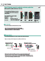
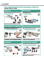
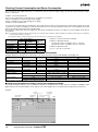
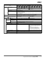
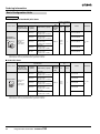
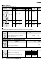
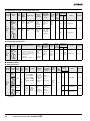
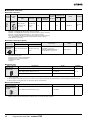
Lineup
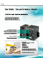
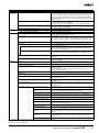
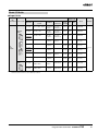
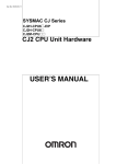
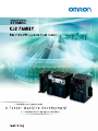
The CJ2 Provides a Complete Lineup
The complete lineup provides high-performance features from machine control to information processing.
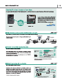
CJ2M
Units
CJ2H
Type
Simple Types
Standard Types
High - end Types
Flagship Types
Models
CJ2M-CPU1 ჱ
CJ2M-CPU3ჱ
CJ2H-CPU6ჱ
CJ2H-CPU6ჱ-EIP
Appearance
Program Capacity
Up to 60 Ksteps
Up to 400 Ksteps
Data Memory Capacity
Up to 160 Kwords
Up to 832 Kwords
I/O Bits
2,560
Basic Instructions(LD)
40ns
16ns
Special instruction (MOV)
120ns
48ns
Floating-point decimal
instructions (SIN)
0.86μs
0.59μs
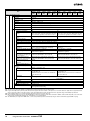
System overhead time
FB Program Area
160μs
270μs
YES
(Equivalent to 20K steps.)
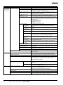
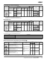
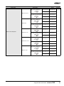
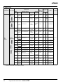
Communications Port
USB Port
Serial Port
EtherNet/IP Port
Serial PLC Links
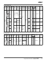
200μs
YES
One Serial Option Board
can be mounted
YES
(RS-232C)
(RS 232C or RS 422A/485)
-
YES
YES
YES
(A Serial Option Board is required)
High-speed Interrupt Function
-
Synchronous Unit Operation
-
Pulse I/O Modules*
100μs
YES
(Up to two Pulse I/O Modules can be mounted)
*A Pulse I/O Module must be mounted for CJ2M CPU Units with unit version 2.0 or later.
YES
(RS-232C)
-
YES
YES
YES
(In combination with a CJ1W NCჱჱ4 Position Control Unit)
-
F-11
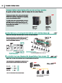
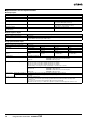
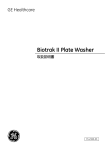
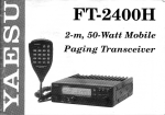
Pulse Outputs
From stepping motors to servos, positioning control can be easily achieved using pulse outputs for up to four axes.
Faster and easier
ȩ3XOVH FRQWURO F\FOH RI PV RI 20521
V &-0 $FKLHYH VPRRWKHU DFFHOHUDWLRQ DQG GHFHOHUDWLRQ
ȩ)DVWHU VWDUWLQJ RI SRVLWLRQ FRQWURO WZLFH DV IDVW DV 20521
V &-0 +HOSV UHGXFH PDFKLQH WDNW WLPH
ȩ,17(55837 )((' LQVWUXFWLRQ ,)((' ([HFXWH KLJKSUHFLVLRQ IHHGLQJ IURP LQWHUUXSW LQSXWV ZLWK MXVW RQH LQVWUXFWLRQ
ȩ&ORVH LQWHJUDWLRQ ZLWK WKH GDWD WUDFH IXQFWLRQ RI WKH &;3URJUDPPHU IRU HDV\ PRQLWRULQJ RI SRVLWLRQLQJ RSHUDWLRQV
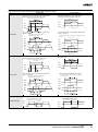
Complete positioning functions
3RVLWLRQLQJ FRQWURO
YDULDWLRQV
Trapezoidal
Acceleration/
Deceleration
Positioning
$FFHOHUDWLRQGHFHOHUDWLRQ
WLPH FDQ EH VKRUWHQHG ZLWK
7UDSH]RLGDO $FFHOHUDWLRQ
'HFHOHUDWLRQ 3RVLWLRQLQJ
IXQFWLRQ DQG 7ULDQJXODU
FRQWURO 'HWDLOHG IXQFWLRQV
DUH SURYLGHG IRU UHGXFLQJ
RXWRIVWHS RSHUDWLRQ IRU
VWHSSLQJ PRWRUV DQG
HOLPLQDWLQJ HUURU
GRZQWLPH
Changing the
Target Position
during Positioning
7KH WDUJHW SRVLWLRQ FDQ EH
FKDQJHG GXULQJ
SRVLWLRQLQJ ,W LV DOVR
SRVVLEOH WR UHYHUVH
GLUHFWLRQ ZKHQ FKDQJLQJ
WKH WDUJHW SRVLWLRQ
2SHUDWLRQ SDWWHUQV
$FFHOHUDWLRQ
6WDUW
IUHTXHQF\
ȩ%DVLF )RUP
7DUJHW VSHHG FRQWURO
Sequential
Positioning
7UDYHO WR PXOWLSOH SUHVHW
SRLQWV FDQ EH H[HFXWHG
7KLV LV HɭHFWLYH IRU
DSSOLFDWLRQV VXFK DV
SRVLWLRQLQJ ORDGHUV DQG
XQORDGHUV DW PXOWLSOH
SRLQWV
3&% &RQYH\RU 5DLO :LGWK 3RVLWLRQLQJ
$FKLHYHG ZLWK D VLQJOH 20521
)XQFWLRQ %ORFNV IRU VSHFLI\LQJ DEVROXWH
RU UHODWLYH WUDYHO
3RVLWLRQ &RQWURO 8VLQJ 'DWD 0HDVXUHG DIWHU 6WDUWXS
:KLOH SRVLWLRQ FRQWURO LV EHLQJ H[HFXWHG E\ D
3/6 LQVWUXFWLRQ DQRWKHU 3/6 LQVWUXFWLRQ FDQ EH
XVHG WR RYHUULGH WKH ɮUVW 3/6 LQVWUXFWLRQ
'HFHOHUDWLRQ
6SHFLɮHG QXPEHU
RI WUDYHO SXOVHV
ȩ6HWWLQJ $FFHOHUDWLRQ $FFHOHUDWLRQ
DQG 'HFHOHUDWLRQ
6HSDUDWHO\
'HFHOHUDWLRQ
6FXUYH
DFFHOHUDWLRQ
6FXUYH
GHFHOHUDWLRQ
ȩ6FXUYH $FFHOHUDWLRQ
'HFHOHUDWLRQ 6HWWLQJ
ȩ7ULDQJXODU &RQWURO
&RQWUROOHU
7UDSH]RLGDO FRQWURO
3/6 LQVWUXFWLRQ
ȩ6WDUWLQJ 7UDSH]RLGDO &RQWURO
56&
&DPHUD
7DUJHW SRVLWLRQ
IUHTXHQF\
DFFHOHUDWLRQ
GHFHOHUDWLRQ FKDQJHG
7UDYHO VWDUW
6HUYR 'ULYHU
HJ 60$5767(3 37
ȩ &KDQJLQJ WKH 7DUJHW 3RVLWLRQ ZLWK
$QRWKHU ,QVWUXFWLRQ
6HUYRPRWRU
+LJKSUHFLVLRQ ,QWHUUXSW IRU 3RVLWLRQLQJ
Interrupt Feeding
,W LV SRVVLEOH WR FKDQJH WR
SRVLWLRQLQJ FRQWURO GXULQJ
VSHHG FRQWURO ,QWHUUXSW
IHHGLQJ FDQ EH H[HFXWHG
DIWHU WKH LQWHUUXSW IRU D
VSHFLɮHG QXPEHU RI SXOVHV
6HWWLQJ DQG VWDUWLQJ LQWHUUXSW
IHHGLQJ LV SRVVLEOH ZLWK RQH
LQVWUXFWLRQ ZLWKRXW XVLQJ DQ
LQWHUUXSW WDVN
6SHFLDO LQVWUXFWLRQV
20521 )XQFWLRQ %ORFNV
$SSOLFDWLRQ H[DPSOHV
6SHHG FRQWURO
,)((' LQVWUXFWLRQ
$ VSHFLɮHG QXPEHU RI SXOVHV DUH
RXWSXW DQG
WKHQ SRVLWLRQLQJ VWRSV
$FKLHYHG ZLWK D VLQJOH 20521
)XQFWLRQ %ORFN IRU LQWHUUXSW IHHGLQJ
6KHHW IHHGLQJ
GLUHFWLRQ
&RQVWDQW VKHHW OHQJWK
IURP GHWHFWLRQ RI PDUN
XQWLO KHDW ZHOGLQJ
7UDYHO VWDUW
3&% 5DFN
3RVLWLRQLQJ
$FKLHYHG ZLWK D VLQJOH 20521
)XQFWLRQ %ORFN IRU VSHFLI\LQJ
VHTXHQWLDO SRVLWLRQLQJ
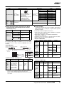
System Design Guide
System Configuration ........................................................................................2
Checking Current Consumption and Power Consumption ...............................10
Dimensions ......................................................................................................11
General Specifications .....................................................................................14
Performance Specifications .............................................................................15
Function Specifications ....................................................................................19
Specifications for Pulse I/O Functions .............................................................24
1
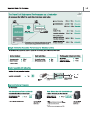
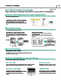
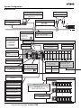
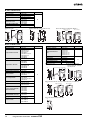
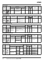
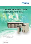
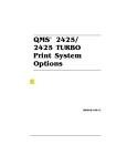
System Configuration
■ Basic System
FA Communication Software
FA Wireless Lan Units
SYSMAC Gateway
CX-Compolet
WE70
Programmable Terminal (PT)
Industrial Switching Hubs
NS Series
WS41-03B
WS41-05B/C
CJ2H-CPU6@-EIP
CJ2H-CPU6@
CJ2M-CPU3@
CJ2M-CPU1@
CJ1W-PA205C
CJ1W-PA205R
CJ1W-PA202
CJ1W-PD025
CJ1W-PD022
AP
PLC
Ethernet Cable
CJ2 CPU Units
CJ1 Power Supply Units
P
Commercially available
100Base-TX twisted-pair cable
CPU Rack (Backplane-free Structure)
CJ1 Battery
CJ1 I/O Control Unit
CJ1 End Cover
CJ1W-BAT01
CJ1W-IC101
CJ1W-TER01
Programming Devices
IC101
OUT
CJ1W PA205C
POWER
AC100 240V
NPUT
Years
L1
CX-One
(e.g., CX-Programmer)
TEST
ALARM
OUTPUT
DC30V 50mA
NORMAL ON
ALARM OFF
L
+
NC
NC
USB Cable
Commercially available USB cable
Serial Option Board
Note: Only CJ2M-CPU3@
can be mounted.
Pulse I/O Modules
Memory Card
HMC-EF@@@
(128 MB, 256 MB, 512 MB)
Note: Only CJ2M-CPU Units
can be mounted.
RS-422A
/485
CP1W-CIF01 CP1W-CIF11
CP1W-CIF12
RS-232C
CJ2M-MD211
CJ2M-MD212
CJ1 Basic I/O Units
CJ1 Special I/O Units
CJ1 CPU Bus Units
Note: A maximum of 10 Units
can be mounted.
Programmable Terminal (PT)
NS Series
Expansion Rack (Backplane-free Structure)
101
CJ1W- A 05C
OUT
PO ER
A 1 0 2 0V
NP T
RS-232C Cable for PT
XW2Z-200T/500T
RS-232C Cable for
Personal Computer
Y
L1
TES
Expansion Cables
CS1W-CN@@3
(30 cm, 70 cm, 2 m, 3 m, 5 m, 10 m, 12 m)
(Same cable as CS series)
N
N
I 01
CJ1W- A 05C
OUT
PO ER
A 1 0 2 0V
NP T
2N
Y
TES
N
N
XW2Z-200S/500S-CV
CJ1 I/O Interface Unit
RS-422A Adapter
CJ1W-II101
I 01
OUT
PO ER
A 1 0 2 0V
NP T
Y
L
CJ1W-CIF11
2
N
N
2
Programmable Controllers SYSMAC CJ2
TES
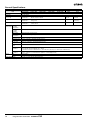
■ Configuration Units
CJ1 Basic I/O Units
8-point Units
16-point Units
32-point Units
64-point Units
Input Units
● DC Input Unit
CJ1W-ID231
CJ1W-ID232
CJ1W-ID233 High-speed type
● DC Input Unit
CJ1W-ID211
CJ1W-ID212 High-speed type
● AC Input Unit
CJ1W-IA111
● DC Input Unit
CJ1W-ID201
● AC Input Unit
CJ1W-IA201
● DC Input Unit
CJ1W-ID261
CJ1W-ID262
Output Units
● Relay Contact Output Unit
(independent commons)
CJ1W-OC201
● Triac Output Unit
CJ1W-OA201
● Transistor Output Units
CJ1W-OD201
CJ1W-OD203
CJ1W-OD202
CJ1W-OD204
● Transistor Output Units
CJ1W-OD231
CJ1W-OD233
CJ1W-OD234 High-speed type
CJ1W-OD232
● Relay Contact Output Unit
CJ1W-OC211
● Transistor Output Units
CJ1W-OD211
CJ1W-OD213 High-speed type
CJ1W-OD212
● Transistor Output Units
CJ1W-OD261
CJ1W-OD263
CJ1W-OD262
I/O Units
---
(16 inputs, 16 outputs)
● DC Input/Transistor Output Units
CJ1W-MD231
CJ1W-MD233
CJ1W-MD232
---
32 inputs, 32 outputs
● DC Input/Transistor Output Units
CJ1W-MD261
CJ1W-MD263
32 inputs, 32 outputs
● TTL I/O Unit
CJ1W-MD563
Other Units
● Interrupt Input Unit
CJ1W-INT01
---
---
● Quick-response Input Unit
CJ1W-IDP01
● B7A Interface Units
(64 inputs)
CJ1W-B7A14
(64 outputs)
CJ1W-B7A04
(32 inputs, 32 outputs)
CJ1W-B7A22
CJ1 Special I/O Units and CPU Bus Units
■ Process I/O Units
● Isolated-type Units with Universal Inputs
CJ1W-PH41U
CJ1W-AD04U
■ High-speed Counter Units
CJ1W-CT021
■ Position Control Units
CJ1W-NC214
● Isolated-type Thermocouple Input Units
CJ1W-NC414 High-speed type
CJ1W-PTS15
CJ1W-NC234 High-speed type
CJ1W-PTS51
CJ1W-NC434 High-speed type
● Isolated-type Resistance
CJ1W-NC113
Thermometer Input Units
CJ1W-NC213
CJ1W-PTS16
CJ1W-NC413
CJ1W-PTS52
CJ1W-NC133
● Isolated-type DC Input Unit
CJ1W-NC233
CJ1W-PDC15
CJ1W-NC433
■ Analog I/O Units
■ Position Control Unit with EtherCAT
● Analog Input Units
interface
CJ1W-AD042 High-speed type
CJ1W-NC281
CJ1W-AD081-V1
CJ1W-NC481
CJ1W-AD041-V1
CJ1W-NC881
● Analog Output Units
CJ1W-NCF81
CJ1W-DA042V High-speed type
CJ1W-NC482
CJ1W-DA08V
CJ1W-NC882
CJ1W-DA08C
■ Position Control Unit with
CJ1W-DA041
MECHATROLINK-II interface
CJ1W-DA021
CJ1W-NC271
● Analog I/O Units
CJ1W-NC471
CJ1W-MAD42
CJ1W-NCF71
CJ1W-NCF71-MA
■ Temperature Control Units
CJ1W-TC001, CJ1W-TC002
■ Motion Control Unit with
CJ1W-TC003, CJ1W-TC004
MECHATROLINK-II interface
CJ1W-TC101, CJ1W-TC102
CJ1W-MCH71
CJ1W-TC103, CJ1W-TC104
High-speed type
■ Serial Communications Units
CJ1W-SCU22 High-speed type
CJ1W-SCU32 High-speed type
CJ1W-SCU42 High-speed type
CJ1W-SCU21-V1
CJ1W-SCU31-V1
CJ1W-SCU41-V1
■ ID Sensor Units
CJ1W-V680C11
CJ1W-V680C12
CJ1W-V600C11
CJ1W-V600C12
■ EtherNet/IP Unit
CJ1W-EIP21
■ Ethernet Unit
CJ1W-ETN21
■ Controller Link Units
CJ1W-CLK23
■ FL-net Unit
CJ1W-FLN22
■ DeviceNet Unit
CJ1W-DRM21
■ CompoNet Master Unit
CJ1W-CRM21
■ High-speed Data Storage Unit
CJ1W-SPU01-V2
■ CompoBus/S Master Unit
CJ1W-SRM21
Note: Windows is a registered trademark of Microsoft Corporation in the USA. MECHATROLINK II is a registered trademark of the MECHATROLINK Members Association.
Other company names and product names etc. are the trademarks or registered trademarks of their respective companies.
Programmable Controllers SYSMAC CJ2
3
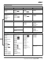
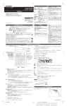
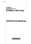
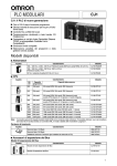
■ CJ-series CPU Racks
A CJ-series CPU Rack consists of a CPU Unit, Power Supply Unit, Configuration Units (Basic I/O Units, Special I/O Units, and CPU Bus
Units), and an End Cover.
CJ2H CPU Units
CJ2M CPU Units
End Cover
CJ1W-TER01
CPU Unit
CJ2H-CPU6@-EIP
CJ2H-CPU6@
(One End Cover is provided
as a standard accessory
with the CPU Unit.)
I/O Control Unit
CJ1W-IC101
Power Supply Unit
CJ1W-P@@@ (@)
(Only connected to the left
of the CPU unit.)
(Required only when connecting
to an Expansion Rack.)
SYSMAC
CJ2H
CPU64-E P
CJ1W PA205C
POWER
PROGRAMMAB E
CONTRO LER
C101
MS
NS
COMM
100M
10M
RUN
ERR ALM
INH
PRPHL
COMM
BKUP
End Cover
CJ1W-TER01
(One End Cover is provided as a
standard accessory with the CPU Unit.)
(Required only when connecting
to an Expansion Rack.)
C101
OUT
OUT
CJ1W PA205C
POWER
UN T
No
AC100-240V
NPUT
OPEN
W SE TING
ATTE Y
Years
L
M PWR
TEST
L2/N
AC100 240V
INPUT
NOD
No
Years
L1
USY
CPU
Rack
CPU Unit
CJ2M-CPU3@
CJ2M-CPU1@
Pulse I/O Modules
CJ2M-MD211
I/O Control Unit
CJ2MMD212
CJ1W-IC101
Power Supply Unit
CJ1W-P@@@ (@)
16
16
TEST
PER PHERAL
L2 N
ALARM
OUTPUT
DC30V 0mA
NORMAL ON
ALARM OFF
L
CPU
Rack
PORT
+
100BASE TX
10BASE T
NC
NC
ALARM
OUTPUT
DC30V 0mA
L
NORMAL ON
ALARM OFF
+
NC
NC
CJ-series Basic I/O Units
CJ-series Special I/O Units
CJ-series CPU Bus Units
CJ-series Basic I/O Units
CJ-series Special I/O Units
CJ-series CPU Bus Units
Total: 10 Units max
Total: 10 Units max
RS-232C
RS-422A/485
Serial Option Board
CP1W-CIF01 CP1W-CIF11
CP1W-CIF12
(CJ2M-CPU3@ Only.)
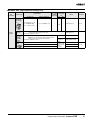
● Required Units
Rack
CPU Rack
Unit name
Required number of Units
Power Supply Unit
1
CPU Unit
1
Pulse I/O Modules
Required only for using Pulse I/O. Up to two Pulse I/O Modules can be connected to a CJ2M CPU Unit.
They must be connected immediately to the left of the CPU Unit.
Serial Option Board
One Serial Option Board can be mounted in the CJ2M-CPU3@.
I/O Control Unit
Required only for mounting to an Expansion Rack. Mount the I/O Control Unit immediately to the right of the CPU Unit.
Number of Configuration
Units
10 max. (Same for all models of CPU Unit.)
(The number of Basic I/O Units, Special I/O Units, and CPU Bus Units can be varied. The number does not include the
I/O Control Unit.)
End Cover
1 (Included with CPU Unit.)
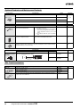
● Types of Units
In the SYSMAC CJ Series, Units are classified into the following three types. The number of Racks differs depending on the type.
Type
Appearance (example)
Description
Unit recognition method
Max. Units mountable
per CPU Unit
Basic I/O Units
Units with contact inputs and contact outputs.
Recognized by the CPU Unit according to the position of the Rack and
slot.
A maximum of 40 Units
can be mounted.
Special I/O
Units
Special I/O Units provide more advanced functions
than do Basic I/O Units, including I/O other than
contact inputs and contact outputs.
Examples of Special I/O Units are Analog I/O
Units and High-speed Counter Units. They differ
from CPU Bus Units (including Network Communications Units) in having a smaller area for
exchanging data with the CPU Unit.
Recognized by the CPU Unit according to the unit number (0 to 95) set
with the rotary switches on the front
panel.
A maximum of 40 Units
can be connected. (Multiple unit numbers are allocated per Unit,
depending on the model
and settings.)
CPU Bus Units
CPU Bus Units exchange data with the CPU Unit Recognized by the CPU Unit accordvia the CPU Bus.
ing to the unit number (0 to F) set with
Examples of CPU Bus Units are Network Commu- the rotary switch on the front panel.
nications Units and Serial Communications Units.
They differ from Special I/O Units in having a
larger area for exchanging data with the CPU Unit.
4
Programmable Controllers SYSMAC CJ2
A maximum of 16 Units
can be mounted.
■ CJ-series Expansion Racks
A CJ-series Expansion Rack consists of a Power Supply Unit, an I/O Interface Unit, Configuration Units (Basic I/O Units, Special I/O
Units, and CPU Bus Units), and an End Cover.
CPU Unit
CJ2H-CPU@@-EIP
Power Supply Unit
CJ1W-P@@@@(@)
I/O Control Unit
CJ1W-IC101
CPU Rack
I/O Interface Unit
CJ1W-II101
Configuration Units: 10 max.
I/O Connecting Cable
CS1W-CN@@3
Power Supply Unit
CJ1W-P@@@@(@)
Expansion
Rack
Total
cable
length
≤ 12 m
I/O Interface Unit
CJ1W-II101
Configuration Units: 10 max.
I/O Connecting Cable
CS1W-CN@@3
Power Supply Unit
CJ1W-P@@@@(@)
Expansion
Rack
I/O Interface Unit
CJ1W-II101
Number of Expansion Racks:
Up to 3 Expansion Racks can be connected.
Configuration Units: 10 max.
I/O Connecting Cable
CS1W-CN@@3
Power Supply Unit
CJ1W-P@@@@(@)
Expansion
Rack
Configuration Units: 10 max.
● Required Units
Rack
CPU Rack
Expansion
Rack
Unit name
Required number of Units
I/O Control Unit
One Unit. Required only when an Expansion Rack is used. Mount the I/O Control Unit immediately to the right
of the CPU Unit. (See note 1.)
Power Supply Unit
One Unit
I/O Interface Unit
One Unit. Mount the I/O Interface Unit immediately to the right of the Power Supply Unit. (See note 2.)
Number of Configuration Units
Ten Units max. (The number of Basic I/O Units, Special I/O Units, and CPU Bus Units can be varied.
This number does not include the I/O Interface Unit.)
End Cover
One (Included with the I/O Interface Unit.)
Note 1. Mounting the I/O Control Unit in any other location may cause faulty operation.
2. Mounting the I/O Interface Unit in any other location may cause faulty operation.
● Maximum Number of Configuration Units That Can Be Mounted
CPU Unit
CJ2H
Model
CJ2H-CPU68 (-EIP)
Total Units
40
No. of Units on CPU Rack
10 per Rack
No. of Expansion Racks
3 Racks x 10 Units
CJ2H-CPU67 (-EIP)
CJ2H-CPU66 (-EIP)
CJ2H-CPU65 (-EIP)
CJ2H-CPU64 (-EIP)
CJ2M
CJ2M-CPU35
CJ2M-CPU34
CJ2M-CPU33
CJ2M-CPU32
CJ2M-CPU31
CJ2M-CPU15
CJ2M-CPU14
CJ2M-CPU13
CJ2M-CPU12
CJ2M-CPU11
Note: It may not be possible to mount the maximum number of configuration Units depending on the specific Units that are mounted. Refer to the next page for details.
Programmable Controllers SYSMAC CJ2
5
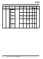
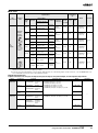
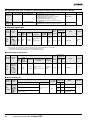
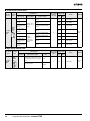
● Configuration Units
CJ-series Special I/O Units
Type
Special I/O
Units
Name
Specifications
Generalpurpose
Universal
Analog Input
Unit
4 inputs, fully universal
Analog Input
Units
8 inputs (4 to 20 mA,
1 to 5 V, etc.)
CJ1W-AD081-V1
4 inputs (4 to 20 mA,
1 to 5 V, etc.)
CJ1W-AD041-V1
4 inputs (4 to 20 mA,
1 to 5 V, etc.)
CJ1W-AD042
4 outputs (1 to 5 V,
4 to 20 mA, etc.)
CJ1W-DA041
2 outputs (1 to 5 V,
4 to 20 mA, etc.)
CJ1W-DA021
8 outputs (1 to 5 V,
0 to 10 V, etc.)
CJ1W-DA08V
8 outputs (4 to 20 mA)
CJ1W-DA08C
Analog Output
Units
Unit No.
Number of
mountable
Units
Current
consumption
(A)
Weight
5 VDC 24 VDC
10 words
100 words
0 to 95
40 Units
0.32
---
150 g max.
10 words
100 words
0 to 95
40 Units
0.42
---
140 g max.
10 words
100 words
0 to 95
40 Units
0.42
---
140 g max.
10 words
100 words
0 to 95
40 Units
0.52
---
150 g max.
10 words
100 words
0 to 95
40 Units
0.12
---
150 g max.
10 words
100 words
0 to 95
40 Units
0.12
---
150 g max.
10 words
100 words
0 to 95
40 Units
0.14
---
150 g max.
CJ1W-AD04U
4 outputs (1 to 5 V,
0 to 10 V, etc.)
Analog I/O
Unit
4 inputs (1 to 5 V,
4 to 20 mA, etc.)
2 outputs (1 to 5 V,
4 to 20 mA, etc.)
Isolated-type
High-resolution
Universal Input
Unit
4 inputs, fully universal
Resolution:
1/256,000, 1/64,000,
1/16,000
4 thermocouple inputs
Isolated-type
Thermocouple 2 thermocouple inputs
Input Units
CJ1W-DA042V
10 words
100 words
0 to 95
40 Units
0.14
---
150 g max.
10 words
100 words
0 to 95
40 Units
0.40
---
150 g max.
10 words
100 words
0 to 95
40 Units
0.58
---
150 g max.
10 words
100 words
0 to 95
40 Units
0.30
---
150 g max.
CJ1W-MAD42
CJ1W-PH41U
CJ1W-PTS51
10 words
100 words
0 to 95
40 Units
0.25
---
150 g max.
CJ1W-PTS15
10 words
100 words
0 to 95
40 Units
0.18
---
150 g max.
10 words
100 words
0 to 95
40 Units
0.25
---
150 g max.
10 words
100 words
0 to 95
40 Units
0.18
---
150 g max.
10 words
100 words
0 to 95
40 Units
0.18
---
150 g max.
20 words
200 words
0 to 94
(uses words
for 2 unit
numbers)
40 Units
0.25
---
150 g max.
20 words
200 words
0 to 94
(uses words
for 2 unit
numbers)
40 Units
0.25
---
150 g max.
20 words
200 words
0 to 94
(uses words
for 2 unit
numbers)
40 Units
0.25
---
150 g max.
20 words
200 words
0 to 94
(uses words
for 2 unit
numbers)
40 Units
0.25
---
150 g max.
20 words
200 words
0 to 94
(uses words
for 2 unit
numbers)
40 Units
0.25
---
150 g max.
20 words
200 words
0 to 94
(uses words
for 2 unit
numbers)
40 Units
0.25
---
150 g max.
2 control loops,
temperature-resistance
CJ1W-TC103
thermometer inputs,
NPN outputs, heater
burnout detection
20 words
200 words
0 to 94
(uses words
for 2 unit
numbers)
40 Units
0.25
---
150 g max.
2 control loops,
temperature-resistance
thermometer inputs,
CJ1W-TC104
PNP outputs, heater
burnout detection
20 words
200 words
0 to 94
(uses words
for 2 unit
numbers)
40 Units
0.25
---
150 g max.
Isolated-type
Resistance
Thermometer
Input Units
4 resistance
thermometer inputs
CJ1W-PTS52
2 resistance
thermometer inputs
CJ1W-PTS16
Direct Current
Input Unit
DC voltage or DC
current, 2 inputs
CJ1W-PDC15
Temperature
Control Units
4 control loops,
thermocouple inputs,
NPN outputs
4 control loops,
thermocouple inputs,
PNP outputs
2 control loops,
thermocouple inputs,
NPN outputs, heater
burnout detection
2 control loops,
thermocouple inputs,
PNP outputs, heater
burnout detection
4 control loops,
temperature- resistance
thermometer inputs,
NPN outputs
4 control loops,
temperature- resistance
thermometer inputs,
PNP outputs
6
Model
Number of
Number of
words allocated words allocated
(CIO 2000 to
(D20000 to
CIO 2959)
D29599)
CJ1W-TC001
CJ1W-TC002
CJ1W-TC003
CJ1W-TC004
CJ1W-TC101
CJ1W-TC102
Programmable Controllers SYSMAC CJ2
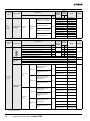
Type
Special I/O
Units
Name
Position
Control Units
Specifications
1 axis, pulse output;
open collector output
2 axes, pulse outputs;
open collector outputs
Model
CJ1W-NC113
CJ1W-NC213
Number of
Number of
words allocated words allocated
(CIO 2000 to
(D20000 to
CIO 2959)
D29599)
1 axis, pulse output;
line driver output
2 axes, pulse outputs;
line driver outputs
CJ1W-NC133
CJ1W-NC233
40 Units
0.25
---
100 g max.
10 words
100 words
0 to 95
40 Units
0.25
---
100 g max.
18 words *3
None
0 to 94
(uses words
for 2 unit
numbers)
5 Units/
Rack
0.27
---
170 g max.
20 words
200 words
0 to 94
(uses words
for 2 unit
numbers)
40 Units
0.36
---
150 g max.
None
0 to 94
(uses words
for 2 unit
numbers)
5 Units/
Rack
0.31
---
220 g max.
10 words
100 words
0 to 95
40 Units
0.25
---
100 g max.
10 words
100 words
0 to 95
40 Units
0.25
---
100 g max.
18 words *3
None
0 to 94
(uses words
for 2 unit
numbers)
5 Units/
Rack
0.27
---
170 g max.
20 words
200 words
0 to 94
(uses words
for 2 unit
numbers)
40 Units
0.36
---
150 g max.
18 words *3
None
0 to 94
(uses words
for 2 unit
numbers)
5 Units/
Rack
0.31
---
220 g max.
None
None
---
---
---
---
50 g max.
10 words
100 words
0 to 95
40 Units
0.26
0.12
120 g max.
20 words
200 words
0 to 94
(uses words
for 2 unit
numbers)
40 Units
0.32
0.24
130 g max.
10 words
100 words
0 to 95
40 Units
0.26
0.13
120 g max.
20 words
200 words
0 to 94
40 Units
0.32
0.26
130 g max.
40 words
400 words
0 to 92
(uses words
for 4 unit
numbers)
24 Units
0.28
---
100 g max.
10 words or
20 words
None
0 to 95 or
0 to 94
40 Units
0.15
---
66 g max.
*6
18 words *3
CJ1W-NC433
CJ1W-NC434
*1, *2
Space Unit *4
ID Sensor
Units
V600-series singlehead type
V600-series two-head
type
High-speed
Counter Unit
CompoBus/S
Master Units
*1.
*2.
*3.
*4.
*5.
*6.
CJ1W-SP001
CJ1W-V600C11
CJ1W-V600C12
V680-series singlehead type
CJ1W-V680C11
V680-series two-head
type
CJ1W-V680C12
Number of counter
channels: 2, Maximum
input frequency:
500 kHz, line driver
compatible *5
CJ1W-CT021
CompoBus/S remote
I/O, 256 bits max.
CJ1W-SRM21
5 VDC 24 VDC
0 to 95
CJ1W-NC234
*1, *2
4 axes, pulse outputs;
line driver outputs
Weight
100 words
CJ1W-NC413
CJ1W-NC414
*1, *2
Current
consumption
(A)
10 words
CJ1W-NC214
*1, *2
4 axes, pulse outputs;
open collector outputs
Unit No.
Number of
mountable
Units
With a CJ2 CPU Unit, up to 10 Configuration Units can be connected in the CPU Rack and in each Expansion Rack. The CJ1W-NC@@4, however, must be
counted as two Units. Configure the Units to satisfy the following formula.
Number of CJ1W-NC@@4 Units × 2 + Number of other Units ≤ 10
For example, if five CJ1W-NC@@4 Units are connected to one Rack, no other Units can be connected.
The Units must be mounted on the CPU Rack to use synchronous unit operation.
In addition to the words allocated in the Special I/O Unit Area, up to 144 words are allocated according to the number of axes and functions uses. Word allocations
are set using the CX-Programmer.
The Space Unit is for Position Control Units.
If interrupts to the CPU Unit are used, mount the Interrupt Input Unit in one of the following slots on the CPU Rack.
• CJ2H-CPU6@-EIP: Slots 0 to 3
• CJ2H-CPU6@ or CJ2M-CPU@@: Slots 0 to 4
Includes the weight of accessory connectors.
Programmable Controllers SYSMAC CJ2
7
Type
Special I/O
Units
8
Name
CompoNet
Master Unit
Specifications
Model
Number of
Number of
words allocated words allocated
(CIO 2000 to
(D20000 to
CIO 2959)
D29599)
Unit No.
Number of
mountable
Units
Current
consumption
(A)
5 VDC 24 VDC
20 words
None
0 to 94
(uses words
for 2 unit
numbers)
40 Units
0.40
---
Communications
mode No. 1:
256 inputs/
256 outputs for Word
Slaves
40 words
None
0 to 92
(uses words
for 4 unit
numbers)
24 Units
0.40
---
Communications
mode No. 2:
512 inputs/
512 outputs for Word
Slaves
80 words
None
0 to 88
(uses words
for 8 unit
numbers)
12 Units
0.40
---
Communications
mode No. 3:
256 inputs/
256 outputs for Word
Slaves and 128
inputs/
128 outputs for Bit
Slaves
80 words
None
0 to 88
(uses words
for 8 unit
numbers)
12 Units
0.40
---
Communications
mode No. 8: 1,024
inputs/ 1,024 outputs
for Word Slaves and
256 inputs/
256 outputs for Bit
Slaves maximum
10 words
Depends on
setting
0 to 95 uses
words for 1
unit
number)
40 Units
0.40
---
CompoNet remote I/O
Communications
mode No. 0:
128 inputs/
128 outputs for Word
Slaves
CJ1W-CRM21
Programmable Controllers SYSMAC CJ2
Weight
130 g max.
CJ-series CPU Bus Units
Type
CPU Bus
Units *1
Name
Specifications
Model
High-speed Analog
Input Unit
4 inputs: 80 µs/2 inputs,
160 µs/4 inputs
Controller Link
Units
Wired data links
Serial
Communications
Units
One RS-232C port and
one RS-422A/485 port
CJ1W-SCU41-V1
Two RS-232C ports
CJ1W-SCU21-V1
Two RS-422A/485 ports
CJ1W-SCU31-V1
Ethernet Units
EtherNet/IP Unit
FL-net Unit
DeviceNet Unit
EtherCATcompatible
Position Control
Units *8
CJ1W-ADG41 *2
CJ1W-CLK23
Two RS-232C ports
High-speed models
CJ1W-SCU22
Two RS-422A/485 ports
High-speed models
CJ1W-SCU32
One RS-232C port and
one RS-422A/485 port
High-speed models
CJ1W-SCU42
100Base-TX, FINS
communications, socket
service, FTP server, and
mail communications
Maximum
number of
Units *1
25 words
0 to F
16 Units
*3
0.65
---
150 g max.
25 words
0 to F
8 Units
0.35
---
110 g max.
25 words
0 to F
16 Units
*3
0.38 *4
---
110 g max.
5 VDC
Weight
24 VDC
0.28 *4
0.38
16 Units
*3
0.28 *4
160 g max.
0.4
120 g max.
0.36 *4
140 g max.
25 words
0 to F
4 Units
0.37
---
100 g max.
25 words
0 to F
*5
0.41
---
94 g max.
25 words
0 to F
4 Units
0.37
---
100 g max.
25 words *6
0 to F
16 Units
*3
0.29
---
118 g max.
*7
25 words
0 to F
16 Units
*3
0.46
---
110 g max.
25 words
0 to F
16 Units
*3
0.36
---
95 g max.
25 words
0 to F
3 Units/
Rack *9
0.60
---
210 g max.
Not used.
0 to F
16 Units
*3
0.56
---
180 g max.
CJ1W-ETN21
Tag data links, FINS
communications, CIP
message
communications, FTP
server, etc.
CJ1W-EIP21
100Base-TX cyclic
transmissions and
message transmissions
CJ1W-FLN22
DeviceNet remote I/O,
2,048 points; Both
Master and Slave
functions, Automatic
allocation possible
without Configurator
Current
consumption (A)
Number of words
allocated (CIO 1500 Unit No.
to CIO 1899)
CJ1W-DRM21
2 servo axes
CJ1W-NC281
4 servo axes
CJ1W-NC481
8 servo axes
CJ1W-NC881
16 servo axes
CJ1W-NCF81
4 servo axes and 64 I/O
slaves
CJ1W-NC482
8 servo axes and 64 I/O
slaves
CJ1W-NC882
Position Control
Units supporting
MECHATROLINK-II
communications
MECHATROLINK-II,
16 axes max.
Motion Control
Units supporting
MECHATROLINK-II
communications
MECHATROLINK-II, Real
axes: 30 max.,
Virtual axes: 2 max.,
Special motion control
language
CJ1W-MCH71
SYSMAC SPU
Unit (High-speed
Storage and
Processing Unit)
One CF card type I/II slot
(used with OMRON
HMC-EF@@@ Memory
Card), one Ethernet port
CJ1W-SPU01-V2
*10
CJ1W-NCF71(-MA)
*1.
Some CJ-series CPU Bus Units are allocated words in the CPU Bus Unit Setup Area. The system must be designed so that the number of words allocated in the
CPU Bus Unit Setup Area does not exceed its capacity. Refer to 4-6-2 CPU Bus Unit Setup Area in CJ2 CPU Unit Software User’s Manual (Cat. No. W473).
There may also be limits due to the capacity of the Power Supply Unit that you are using or the maximum number of Units to which memory can be allocated in
the CPU But Unit Setup Area.
*2. If interrupts to the CPU Unit are used, mount the Interrupt Input Unit in one of the following slots on the CPU Rack.
• CJ2H-CPU6@-EIP: Slots 0 to 3
• CJ2H-CPU6@ or CJ2M-CPU@@: Slots 0 to 4
*3. Up to 15 Units can be connected for a CJ2H-CPU6@-EIP or CJ2M-CPU3@ CPU Unit.
*4. Increases by 0.15 A/Unit when an NT-AL001 RS-232C/RS-422A Link Adapter is used. Increases by 0.04 A/Unit when a CJ1W-CIF11 RS-422A Converter is used.
Increases by 0.20 A/Unit when an NV3W-M@20L Programmable Terminal is used.
*5. Up to seven Units can be connected for a CJ2H-CPU6@-EIP CPU Unit, up to eight Units can be connected for a CJ2H-CPU6@ CPU Unit, and up to two Units
can be connected for a CJ2M CPU Unit.
*6. Slave I/O are allocated in DeviceNet Area (CIO 3200 to CIO 3799).
*7. Includes the weight of accessory connectors.
*8. Only OMNUC G5-series Servo Drives with Built-in EtherCAT can be connected.
*9. When mounting to a CJ-series CPU Rack or a CJ-series Expansion Rack, one of these Units uses the space of three Units.
*10. Use version 2 or higher of the SYSMAC SPU Unit with a CJ2 CPU Unit.
Programmable Controllers SYSMAC CJ2
9
Checking Current Consumption and Power Consumption
After selecting a Power Supply Unit based on considerations such as the power supply voltage, calculate the current and power requirements for each Rack.
Condition 1: Current Requirements
There are two voltage groups for internal power consumption: 5 V and 24 V.
Current consumption at 5 V (internal logic power supply)
Current consumption at 24 V (relay driving power supply)
Condition 2: Power Requirements
For each Rack, the upper limits are determined for the current and power that can be provided to the mounted Units. Design the system
so that the total current consumption for all the mounted Units does not exceed the maximum total power or the maximum current supplied for the voltage groups shown in the following tables.
The maximum current and total power supplied for CPU Racks and Expansion Racks according to the Power Supply Unit model are
shown below.
Note 1. For CPU Racks, include the CPU Unit current and power consumption in the calculations. When expanding, also include the current and power consumption
of the I/O Control Unit in the calculations.
2. For Expansion Racks, include the I/O Interface Unit current and power consumption in the calculations.
Max. current supplied
Power Supply Units
5V
Conditions 1 and 2 below must be satisfied.
Condition 1: Maximum Current
(1) Total Unit current consumption at 5 V ≤ (A) value
(2) Total Unit current consumption at 24 V ≤ (B) value
Condition 2: Maximum Power
(1) × 5 V + (2) × 24 V ≤ (C) value
Max. total
power supplied
24 V (relay driving current)
CJ1W-PA205C
5.0 A
0.8 A
25 W
CJ1W-PA205R
5.0 A
0.8 A
25 W
CJ1W-PA202
2.8 A
0.4 A
14 W
CJ1W-PD025
5.0 A
0.8 A
25 W
CJ1W-PD022
2.0 A
0.4 A
19.6 W
■ Example: Calculating Total Current and Power Consumption
Example: When the Following Units are Mounted to a CJ-series CPU Rack Using a CJ1W-PA205R Power Supply Unit
Unit type
CPU Unit
Model
Voltage group
Quantity
CJ2H-CPU68-EIP
5V
24 V
1
0.820 A
---
I/O Control Unit
CJ1W-IC101
1
0.020 A
---
Basic I/O Units (Input Units)
CJ1W-ID211
2
0.080 A
---
CJ1W-ID231
2
0.090 A
---
CJ1W-OC201
2
0.090 A
0.048 A
Special I/O Unit
CJ1W-DA041
1
0.120 A
---
CPU Bus Unit
CJ1W-CLK23
1
Basic I/O Units (Output Units)
Current consumption
Power consumption
Total
0.350 A
0.820 + 0.020 + 0.080 × 2 + 0.090 ×
2 + 0.090 × 2 + 0.120 + 0.350
--0.048 A × 2
Result
1.83 A (≤ 5.0 A)
0.096 A (≤ 0.8 A)
Total
1.83 × 5 V = 9.15 W
0.096 A × 24 V = 2.30 W
Result
9.15 + 2.30 = 11.45 W (≤ 25 W)
Note: For details on Unit current consumption, refer to Ordering Information.
■ Using the CX-Programer to Display Current Consumption and Width
CPU Rack and Expansion Rack current consumption and width can be displayed by selecting Current Consumption and Width from the
Options Menu in the CJ2 Table Window. If the capacity of the Power Supply Unit is exceeded, it will be displayed in red characters.
Example:
Current
consumption at 5 V
Power Supply
Unit model
10
Long-distance
expansion
Total current
consumption
Current consumption
at 26 V/24 V
Programmable Controllers SYSMAC CJ2
Width
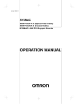
Dimensions
Note: Units are in mm unless specified otherwise.
■ Product Dimensions
Example Rack Widths using CJ1WPA202 Power Supply Unit (AC, 14 W)
S SM C
C 2H
CPU 4 E P
ROGRAMM BLE
ONTRO LER
M
N
COM
00
10
RUN
E R/ LM
NH
PR HL
COMM
B UP
27
U IT
No
SW ET I G
A TERY
N DE
No
CP R
USY
x 6
16
PER PHERAL
90
35.4
PORT
00BASE TX
0BASE T
27.6
W
65
No. of Units
mounted with
31-mm width
1
2
3
4
5
6
7
8
9
10
Rack width (mm)
With
With
CJ2H-CPU6@
CJ2M-CPU3@
139.5
152.7
170.5
183.7
201.5
214.7
232.5
245.7
263.5
276.7
294.5
307.7
325.5
338.7
356.5
369.7
387.5
400.7
418.5
431.7
With
CJ2H-CPU6@-EIP
170.5
201.5
232.5
263.5
294.5
325.5
356.5
387.5
418.5
449.5
With
CJ2M-CPU1@
121.7
152.7
183.7
214.7
245.7
276.7
307.7
338.7
369.7
400.7
● Power Supply Units, CPU Units, and End Covers
Unit/product
Model
CJ1W-PA205C
CJ1W-PA205R
CJ1W-PA202
CJ1W-PD025
CJ1W-PD022
CJ2H-CPU6@-EIP
CJ2H-CPU6@
CJ2M-CPU3@
CJ2M-CPU1@
CJ1W-TER01
Power Supply Unit
CPU Unit
End Cover
Width
80
80
45
60
27
79.8
48.8
62
31
14.7
End Cover
(included with CPU Units)
Power Supply Units
90
90
14.7
65
81.6
W
RS-422A Adapter
CJ1W-CIF11
W=27: CJ1W-PD022
W=45: CJ1W-PA202
W=80: CJ1W-PA205R
CJ1W-PA205C
W=60: CJ1W-PD025
38.8
34
CPU Units
CJ2H-CPU6@-EIP
2.7
66.2
SYSMAC
CJ H
CPU64 E P
P OGRAMMA LE
CO TRO LER
2.7
CJ2M-CPU1@
CJ2M-CPU3@
CJ2H-CPU6@
2.7
66.2
2.7
76.2
76.2
MS
NS
COMM
1 0M
0M
UN
ER /A M
NH
PRPH
COMM
BK P
UN T
o
OPEN
W ETT NG
AT ERY
NO E
No
CPWR
USY
6
16
L
90
90
90
PORT
90
1 0BASE TX
2.7
79.8
65
74.5
48.8
2.7
65
74.5
62
2.7
75
84.5
2.7
31
75
84.5
● Option Boards (CJ2M-CPU3@ only)
● Serial Option Boards
CP1W-CIF01
CP1W-CIF11
CP1W-CIF12
16.5
13.5
35.9
16.5
13.5
35.9
35.9
35.9
37.3
36.4
37.3
37.3
5.1
7.9
8.9
16.5
19.7
30.3
28.2
36.4
15.7
16.5
Programmable Controllers SYSMAC CJ2
11
● Units of Width 20 mm
Unit/product
Model
I/O Control Unit
CJ1W-IC101
Pulse I/O Modules
CJ2M-MD211/212
CJ1W-ID231/232/233
32-point Basic I/O Units
CJ1W-OD231/232/233/234
B7A Interface Unit
CJ1W-B7A22
CJ1W-B7A14
CJ1W-B7A04
CompoBus/S Master Unit
CJ1W-SRM21
Space Unit
CJ1W-SP001
● I/O Control Unit
2.7
● 32-Point I/O Units (CJ1W-ID223@/OD23@)
Fujitsu connector
66.2
68
2.7
MIL connector
(112.5)
90
90
2.7
20
● Pulse I/O Modules (Only CJ2M CPU Unit)
(140)
2.7
Width
90
2.7
65
69.3
20
65
83.8
20
2.7
65
66.5
20
65
83.6
● Units of Width 31 mm
Unit
Model
I/O Interface Unit
CJ1W-II101
8/16-point Basic I/O Units
CJ1W-ID201
CJ1W-ID211/212
CJ1W-IA111/201
CJ1W-OD20@
CJ1W-OD211/212/213
CJ1W-OC201/211
CJ1W-OA201
32-point Basic I/O Units
CJ1W-MD231
CJ1W-MD232/233
CJ1W-ID261
CJ1W-OD261
CJ1W-MD261
64-point Basic I/O Units
Width
CJ1W-INT01
Quick-response Input Unit
CJ1W-IDP01
Analog I/O Units
CJ1W-AD@@@ (-V1)
CJ1W-DA@@@ (@)
CJ1W-MAD42
Process Input Units
CJ1W-PH41U
CJ1W-AD04U
CJ1W-PTS51/52/15/16
CJ1W-PDC15
Temperature Control Units
CJ1W-TC@@@
Position Control Units
CJ1W-NC113/133
CJ1W-NC213/233
CJ1W-NC413/433
Position Control Unit with
EtherCAT interface
CJ1W-NC281
CJ1W-NC481
CJ1W-NC881
CJ1W-NCF81
CJ1W-NC482
CJ1W-NC882
Position Control Unit with
MECHATROLINK-II interface
CJ1W-NCF71
High-speed Counter Unit
CJ1W-CT021
ID Sensor Units
CJ1W-V680C11
CJ1W-V680C12
CJ1W-V600C11
CJ1W-V600C12
Serial Communications
Units
CJ1W-SCU22
CJ1W-SCU32
CJ1W-SCU42
CJ1W-SCU41-V1
CJ1W-SCU21-V1
CJ1W-SCU31-V1
EtherNet/IP Unit
CJ1W-EIP21
Ethernet Unit
CJ1W-ETN21
DeviceNet Unit
CJ1W-DRM21
CompoNet Master Unit
CJ1W-CRM21
FL-net Unit
CJ1W-FLN22
Width
31
● 8/6-point Basic I/O Units,
Interrupt Input Unit, and Highspeed Input Unit
(140)
2.7
68
90
2.7
90
31
2.7
31
2.7
2.7
Fujitsu connector
31
MIL connector
90
2.7
31
65
66.5
(112.5)
● Special I/O Units and CPU Bus Units
2.7
2.7
Programmable Controllers SYSMAC CJ2
65
69.3
65
89
● 64-point Basic I/O Units and 32-point Basic I/O Units (CJ1W-MD23@)
90
12
Model
CJ1W-CLK23
● I/O Interface Unit
CJ1W-ID262
CJ1W-OD262/263
CJ1W-MD263
CJ1W-MD563
Interrupt Input Unit
Unit
Controller Link Units
31
65
83.6
● Units of Width 51 mm
● Unit of Width 62 mm
Unit
Model
SYSMAC SPU
(High-speed Data Storage
Unit)
CJ1W-SPU01-V2
Position Control Units
(High-speed type)
CJ1W-NC214/234
Width
Unit
Model
Position Control Units
(High-speed type)
CJ1W-NC414/434
Width
62
51
● Position Contorol Unit (High-speed model)
CJ1W-NC414/434
84
65
● SYSMAC SPU (High-speed Data Storage Unit)
CJ1W-SPU01-V2
2.7
2.7
90
90
2.7
62
2.7
51
9
65
● Unit of Width 79.8 mm
Unit
Model
Motion Control Unit with
MECHATROLINK-II interface
Width
CJ1W-MCH71
79.8
● Motion Control Unit with MECHATROLINK-II interface
CJ1W-MCH71
90
79.8
65
70.9
■ Mounting Dimensions
SYSMAC
CJ2H
CPU64 EIP
PROG AMMAB E
CONT OLL R
M
N
OMM
10 M
1 M
RUN
ERR ALM
NH
RPHL
COMM
BKUP
27.5
NT
o
SW SE T NG
BA TE Y
■ Mounting Height
OD
o
MC WR
BU Y
16
x 6
PERIPHERAL
35
90
PORT
100BASE TX
10BASE T
27.5
65
A
The mounting height of CJ-series CPU Racks and Expansion
Racks is from 81.6 to 89.0 mm depending on the Units that are
mounted.
Additional height is required to connect Programming Devices
(e.g., CX-Programmer) and Cables. Be sure to allow sufficient
mounting height.
Approx. 100 to 150 mm
DIN Track model number
A
PFP-100N2
16 mm
PFP-100N
7.3 mm
FPP-50N
7.3 mm
81.6 to 89.0 mm
Note: Consider the following points when expanding the configuration:
The total length of I/O Connecting Cable must not exceed 12 m.
I/O Connecting Cables require the bending radius indicated below.
● Expansion Cable
R
R ≥ 69 mm
Note: Outer diameter of cable: 8.6 mm.
Programmable Controllers SYSMAC CJ2
13
General Specifications
Item
CJ2HCPU64 (-EIP)
CPU65 (-EIP)
CPU66 (-EIP)
CJ2MCPU67 (-EIP)
CPU68 (-EIP)
CPU1@
CPU3@
Enclosure
Mounted in a panel
Grounding
Less than 100 Ω
CPU Unit Dimensions
(H × D × W)
CJ2H-CPU6@-EIP : 90 mm × 65 mm × 80 mm
CJ2H-CPU6@ :
90 mm × 65 mm × 49 mm
90 mm × 75 mm
× 31 mm
90 mm × 75 mm
× 62 mm
Weight
CJ2H-CPU6@-EIP : 280 g or less
CJ2H-CPU6@ :
190 g or less
130 g or less
190 g or less
Current Consumption
CJ2H-CPU6@-EIP : 5 VDC, 0.82 A
CJ2H-CPU6@ :
5 VDC, 0.42 A
5 VDC, 0.5 A
Operation
Ambient
Environment Operating
Temperature
0 to 55°C
Ambient
Operating
Humidity
(See note.)
10% to 90% (with no condensation)
Atmosphere
Must be free from corrosive gases.
Ambient Storage
Temperature
−20 to 70°C (excluding battery)
Altitude
2,000 m or less
Pollution Degree 2 or less: Conforms to JIS B3502 and IEC 61131-2.
Battery
Noise Immunity
2 kV on power supply line (Conforms to IEC 61000-4-4.)
Overvoltage
Category
Category II: Conforms to JIS B3502 and IEC 61131-2.
EMC Immunity
Level
Zone B
Vibration
Resistance
Conforms to IEC60068-2-6.
5 to 8.4 Hz with 3.5-mm amplitude, 8.4 to 150 Hz
Acceleration of 9.8 m/s2 for 100 min in X, Y, and Z directions (10 sweeps of 10 min each = 100 min total)
Shock
Resistance
Conforms to IEC60068-2-27.
147 m/s2, 3 times in X, Y, and Z directions (100 m/s2 for Relay Output Units)
Life
5 years at 25°C
Model
CJ1W-BAT01
Applicable Standards
Conforms to cULus, NK, LR and EC Directives.
Note: Without a Serial Option Board.
14
Programmable Controllers SYSMAC CJ2
5 VDC, 0.7 A
Performance Specifications
CJ2HCJ2MCPU64
CPU65
CPU66
CPU67
CPU68
CPU
CPU
CPU
CPU
CPU
(-EIP)
(-EIP)
(-EIP)
(-EIP)
(-EIP)
11/31
12/32
13/33
14/34
15/35
User Memory
50K
100K
150K
250K
400K
5K
10K
20K
30K
60K
steps
steps
steps
steps
steps
steps
steps
steps
steps
steps
I/O Bits
2,560 bits
Processing
Overhead Processing Time *1
Normal Mode: CJ2H-CPU6@-EIP : 200 µs
Normal Mode: CJ2M-CPU3@:
270 µs
CJ2H-CPU6@ :
100 µs
CJ2M-CPU1@:
160 µs
Speed
Execution Time
Basic Instructions: 0.016 µs min.;
Basic Instructions: 0.04 µs min.;
Special Instructions: 0.048 µs min.
Special Instructions: 0.06 µs min.
Interrupt task startup time: 17 µs *2 or 26 µs
Interrupt task startup time: 31 µs
Interrupts
I/O Interrupts and
(30 µs for unit version 1.0)
External Interrupts
Return times to cyclic tasks: 10 µs
Return times to cyclic tasks: 8 µs *2 or 11 µs
(15 µs for unit version 1.0)
Scheduled Interrupts
Minimum time interval: 0.2 ms *2
Minimum time interval: 0.4 ms
(set in 0.1-ms increments)
(set in 0.1-ms increments)
Interrupt task startup time: 13 µs *2 or 22 µs
Interrupt task startup time: 30 µs
(27 µs for unit version 1.0)
Return times to cyclic tasks: 8 µs *2 or 11 µs
Return time to cyclic task: 11 µs
(15 µs for unit version 1.0)
Maximum Number of Connectable Units
Total per CPU Rack or Expansion Rack: 10 Units max.;
Total per PLC: 40 Units max.
Basic I/O Units
No limit
However, a maximum of two CJ1W-INT01 Interrupt Input Units can be mounted.
Special I/O Units
Units for up to 96 unit numbers can be mounted.
(Unit numbers run from 0 to 95. Units are allocated between 1 and 8 unit numbers.)
CPU Bus Units
CJ2M-CPU3@: 15 Units max.
CJ2M-CPU1@: 16 Units max.
Pulse I/O Modules
2 Units max. *3
Slots for which interrupts can be used Slots 0 to 4 on CPU Rack
Maximum Number of Expansion Racks
3 max.
CIO Area
I/O Area
2,560 bits (160 words): Words CIO 0000 to CIO 0159
Link Area
3,200 bits (200 words): Words CIO 1000 to CIO 1199
Synchronous Data Refresh Area
1,536 bits (96 words): Words CIO 1200 to CIO 1295 --CPU Bus Unit Area
6,400 bits (400 words): Words CIO 1500 to CIO 1899
Special I/O Unit Area
15,360 bits (960 words): Words CIO 2000 to CIO 2959
Pulse I/O Area
--20 inputs, 12 outputs (CIO 2960 to CIO 2963)
Serial PLC Link Words
--1,440 bits (90 words): Words CIO 3100 to CIO 3189
DeviceNet Area
9,600 bits (600 words): Words CIO 3200 to CIO 3799
Internal I/O Area
3,200 bits (200 words): Words CIO 1300 to CIO 1499 (Cannot be used for external I/O.)
37,504 bits (2,344 words): Words CIO 3800 to CIO 6143 (Cannot be used for external I/O.)
Work Area
8,192 bits (512 words): Words W000 to W511 (Cannot be used for external I/O.)
Holding Area
8,192 bits (512 words): Words H000 to H511
Bits in this area maintain their ON/OFF status when PLC is turned OFF or operating mode is changed.
Words H512 to H1535: These words can be used only for function blocks. They can be used only for function
block instances (i.e., they are allocated only for internal variables in function blocks).
Auxiliary Area
Read-only: 31,744 bits (1,984 words)
• 7,168 bits (448 words): Words A0 to A447
• 24,576 bits (1,536 words): Words A10000 to A11535 *4
Read/write: 16,384 bits (1,024 words) in words A448 to A1471 *4
Temporary Area
16 bits: TR0 to TR15
Timer Area
4,096 timer numbers (T0000 to T4095 (separate from counters))
Counter Area
4,096 counter numbers (C0000 to C4095 (separate from timers))
DM Area
32k words *5
DM Area words for Special I/O Units: D20000 to D29599 (100 words × 96 Units)
DM Area words for CPU Bus Units: D30000 to D31599 (100 words × 16 Units)
EM Area
32k words/bank × 25 banks max.:
32k words/bank × 4 banks max.:
E00_00000 to E18_32767 max. *5, *6
E00_00000 to E3_32767 max. *5
32K
32K
32K
32K words × 1 bank
32K words × 4 banks
32K
32K
words ×
words ×
words × words × words ×
4 banks 4 banks 10 banks 15 banks 25 banks
Item
*1.
*2.
*3.
*4.
*5.
*6.
The following times are added if EtherNet/IP data tag links are used for the CJ2H-CPU6@-EIP.
Normal operation:
100 µs + Number of transfer words x 0.33 µs
High-speed interrupt enabled: 100 µs + Number of transfer words x 0.87 µs
The following time must be added when using EtherNet/IP tag data links for the CJ2M-CPU3@.
100 µs + (No. of words transferred x 1.8 µs)
The following time must be added when using Pulse I/O Modules with a CJ2M CPU Unit: 10 µs x Number of Pulse I/O Modules.
This applies when High-speed interrupt function is used.
Supported only by CJ2M CPU Units with unit version 2.0 or later. A Pulse I/O Module must be mounted.
A960 to A1471 and A10000 to A11535 cannot be accessed by CPU Bus Units, Special I/O Units, PTs, and Support Software that do not specifically support the
CJ2 CPU Units.
Bits in the EM Area can be addressed either by bit or by word. These bits cannot be addressed by CPU Bus Units, Special I/O Units, PTs, and Support Software
that do not specifically support the CJ2 CPU Units.
EM banks D to 18 cannot be accessed by CPU Bus Units, Special I/O Units, PTs, and Support Software that do not specifically support the CJ2 CPU Units.
Programmable Controllers SYSMAC CJ2
15
Item
Banks for
which bits
can be forceset/reset *7
CPU64
(-EIP)
Using EM Area force-setting/resetting Banks 0
to 3 hex
Using automatic address allocation
Bank 3
hex
specifications
Index Registers
Cyclic Task Flag Area
Memory Card
Operating Modes
Execution Mode
Programming Languages
Function
Blocks
Maximum number of definitions
Maximum number of instances
FB Program Area
Tasks
Type of Tasks
Number of Tasks
Symbols
(Variables)
Type of Symbols
Data Type of Symbols
Maximum Size of Symbol
Array Symbols (Array Variables)
Number of Array Elements
Number of Registrable Network
Symbols (Tags) *8
Length of Network Symbol (Tag)
Name *8
Encoding of Network Symbols (Tags)
*8
CPU65
(-EIP)
Banks 0
to 3 hex
Bank 3
hex
CJ2HCPU66
(-EIP)
Banks 0
to 9 hex
Banks 6
to 9 hex
CPU67
(-EIP)
Banks 0
to E hex
Banks 7
to E hex
CPU68
CPU
CPU
(-EIP)
11/31
12/32
Banks 0 Bank 0 hex
to 18 hex
Banks 11
--to 18 hex
CJ2MCPU
13/33
CPU
CPU
14/34
15/35
Banks 0 to 3 hex
IR0 to IR15
These are special registers for storing PLC memory addresses for indirect addressing. (Index Registers can
be set so that they are unique in each task or so that they are shared by all tasks.)
128 flags
128 MB, 256 MB, or 512 MB
PROGRAM Mode: Programs are not executed. Preparations can be executed prior to program execution in
this mode.
MONITOR Mode: Programs are executed, and some operations, such as online editing, and changes to
present values in I/O memory, are enabled in this mode.
RUN Mode:
Programs are executed. This is the normal operating mode.
Normal Mode
Ladder Logic (LD),
Sequential Function Charts (SFC),
Structured Text (ST), and
Instruction Lists (IL)
2,048
256
2,048
2,048
256
2,048
--20K steps
Cyclic tasks
Interrupt tasks (Power OFF interrupt tasks, scheduled interrupt tasks, I/O interrupt tasks, and external
interrupt tasks, and input interrupt tasks *3)
Cyclic tasks: 128
Interrupt tasks: 256
(Interrupt tasks can be defined as cyclic tasks to create extra cyclic tasks. Therefore, the total number of
cyclic tasks is actually 384 max.)
• Local symbols: Can be used only within a single task in the PLC.
• Global symbols: Can be used in all tasks in the PLC.
• Network symbols (tags) *8: I/O memory in the CPU Unit can be externally accessed using symbols,
depending on parameter settings.
• BOOL (bit)
• UINT (one-word unsigned binary)
• UDINT (two-word unsigned binary)
• ULINT (four-word unsigned binary)
• INT (one-word signed binary)
• DINT (two-word signed binary)
• LINT (four-word signed binary)
• UINT BCD (one-word unsigned BCD) *9
• UDINT BCD (two-word unsigned BCD) *9
• ULINT BCD (four-word unsigned BCD) *9
• REAL (two-word floating-point)
• LREAL (four-word floating-point)
• CHANNEL (word) *9
• NUMBER (constant or number) *9
• WORD (one-word hexadecimal)
• DWORD (two-word hexadecimal)
• LWORD (four-word hexadecimal)
• STRING (1 to 255 ASCII characters)
• TIMER *10
• COUNTER *10
• user-defined data types (delta structures) *11
32k words
One-dimensional arrays
32,000 elements max.
20,000 max.
2,000 max.
255 bytes max.
UTF-8
*7.
With CJ2H CPU Units with unit version 1.2 or later, force-setting/resetting bits in the EM Area is possible either for banks that have been specified for automatic
address assignment or for banks specified for the EM Area force-set/reset function. With CJ2M CPU Units, force-setting/resetting bits in the EM Area is possible
only for banks specified for the EM Area force-set/reset function.
*8. Supported only by the CJ2H-CPU6@-EIP and CJ2M-CPU3@.
*9. This data type cannot be used in Function blocks.
*10. This data type can be used only in Function blocks.
*11. Supported only when CX-Programmer version 9.0 or later is used.
16
Programmable Controllers SYSMAC CJ2
CJ2HItem
Data Tracing
Memory Capacity
CPU64
(-EIP)
CPU65
(-EIP)
8,000 words
CPU66
(-EIP)
16,000
words
CJ2MCPU67
(-EIP)
CPU68
(-EIP)
32,000 words
(Up to 32k words x 25 banks when EM is specified in
CX-Programmer)
Number of Samplings
Comm
unicati
ons
CPU
12/32
CPU
13/33
CPU
14/34
CPU
15/35
8,000 words
(Up to 32k words x 4 banks when EM is specified in
CX-Programmer)
Bits = 31, one-word data =16, two-word data = 8, four-word data = 4
Sampling Cycle
1 to 2,550 ms (Unit: 1 ms)
Trigger Conditions
ON/OFF of specified bit
Data comparison of specified word
Data size: 1 word, 2 words, 4 words
Comparison Method: Equals (=), Greater Than (>), Greater Than or Equals (≥), Less Than (<), Less Than or
Equals (≤), Not Equal (≠)
Delay Value
−32,768 to +32,767 ms
File Memory
Source/
Comment
Memory
CPU
11/31
Memory Card (128, 256, or 512 Mbytes) (Use the Memory Cards provided by OMRON.)
EM file memory (Part of the EM Area can be converted for use as file memory.)
Function block program memory,
comment file, program index file,
symbol tables
Capacity: 3.5 Mbytes
Capacity: 1 Mbytes
Logical Ports for Logical Ports
Communications Extended Logical Ports
8 ports (Used for SEND, RECV, CMND, PMCR, TXDU, and RXDU instructions.)
Class 3
CIP
Communications (Connection Type)
Specification
UCMM (Non-connection
Type)
Number of connections: 64
Peripheral (USB) Port
USB 2.0-compliant B-type connector
Baud Rate
Transmission Distance
Serial Port
64 ports (Used for SEND2, RECV2, CMND2, and PMCR2 instructions.)
Maximum number of clients that can communicate at the same time: 32
Maximum number of servers that can communicate at the same time: 40
12 Mbps max.
5 m max.
Interface: Conforms to EIA RS-232C.
• CJ2M-CPU1@ interface: Conforms to EIA RS-232C.
• CJ2M-CPU3@: No serial ports with default system
One of the following Serial Option Boards can be
mounted.
• CP1W-CIF01 RS-232C Option Board
• CP1W-CIF11 RS-422A/485 Option Board
(not isolated, max. transmission distance: 50 m)
• CP1W-CIF12 RS-422A/485 Option Board
(isolated, max. transmission distance: 500 m)
Communications Method
Half-duplex
Synchronization Method
Start-stop
Baud Rate
0.3, 0.6, 1.2, 2.4, 4.8, 9.6, 19.2, 38.4, 57.6, or 115.2 (kbps)
Transmission Distance
15 m max.
Programmable Controllers SYSMAC CJ2
17
CJ2HItem
Transmission Specifications
EtherNet/IP Port *12
Communications Specifications
Comm
unicati
ons
CPU64
(-EIP)
CPU65
(-EIP)
CPU66
(-EIP)
CJ2MCPU67
(-EIP)
CPU68
(-EIP)
CPU
11/31
CPU
12/32
CPU
13/33
CPU
14/34
CPU
15/35
---
Media Access Method
CSMA/CD
Modulation
Baseband
Transmission Paths
Star
Baud Rate
100 Mbps (100Base-TX)
Transmission Media
Shielded twisted-pair (STP) cable; Categories: 5, 5e
Transmission Distance
100 m (between ethernet switch and node)
Number of Cascade Connections
No restrictions if ethernet switch is used.
CIP Communications: Tag Data Links
---
Number of Connections
256
32
Packet Interval (Refresh
period)
0.5 to 10,000 ms (Unit: 0.5 ms)
Can be set for each connection. (Data will be refreshed
at the set interval, regardless of the number of nodes.)
1 to 10,000 ms (in 0.5-ms increments)
Can be set for each connection. (Data will be refreshed
at the set interval, regardless of the number of nodes.)
Permissible Communications
Band
6,000 packets per second *13
3,000 packets per second *13
Number of Tag Sets
256
32
Type of Tags
CIO, DM, EM, HR, WR, and network symbols
Number of Tags per Connection
8 (Seven tags if PLC status is included in the segment.)
Maximum Link Data Size per
Node
184,832 words
640 words
Maximum Data Size per
Connection
252 or 722 words *14
(Data is synchronized within each connection.)
20 words (Data is synchronized within each
connection.)
Number of Registrable Tag Set 256 (1 connection = 1 segment)
32 (1 connection = 1 segment)
Maximum Tag Set Size
722 words (One word is used when PLC status is
included in the segment.)
20 words (One word is used when PLC status is
included in the segment.)
Maximum Number of Tags
Refreshable in a Single Cycle
of CPU Unit *15
Output/send (CPU Unit to EtherNet/IP): 256
Input/receive (EtherNet/IP to CPU Unit): 256
Output/send (CPU Unit to EtherNet/IP): 32
Input/receive (EtherNet/IP to CPU Unit): 32
Data Size Refreshable in a
Single Cycle of CPU Unit *15
Output/send (CPU to EtherNet/IP): 6,432 words
Input/receive (EtherNet/IP to CPU): 6,432 words
Output/send (CPU Unit to EtherNet/IP): 640 words
Input/receive (EtherNet/IP to CPU Unit): 640 words
Change of Tag Data Link
Parameter Settings during
Operation
OK *16
Multi-cast Packet Filter *17
OK
CIP Communications: Explicit
Messages
Class 3
(Connection Type)
--Number of connections: 128
UCMM (Non-connection Type) Maximum number of clients that can communicate at
the same time: 32
Maximum number of servers that can communicate
at the same time: 32
CIP Routing
FINS Communications
Maximum number of clients that can communicate at
the same time: 16
Maximum number of servers that can communicate
at the same time: 16
OK
(CIP routing is enabled for the following remote Units: CJ1W-EIP21, CJ2H-CPU6@-EIP, CJ2M-CPU3@ and
CS1W-EIP21.)
---
FINS/UDP
OK
FINS/TCP
16 connections max.
EtherNet/IP Conformance Test
Conforms to A5.
EtherNet/IP Interface
10Base-T/100Base-TX
Auto Negotiation/Fixed Setting
*12. The EtherNet/IP port is built into the CJ2H-CPU6@-EIP and CJ2M-CPU3@ only.
*13. “Packets per second” is the number of communications packets that can be processed per second.
*14. Large Forward Open (CIP optional specification) must be supported in order for 505 to 1,444 bytes to be used as the data size. Application is supported between
CS/CJ-series PLCs. When connecting to devices from other manufacturers, make sure that the devices support the Large Forward Open specification.
*15. If the maximum number is exceeded, refreshing will require more than one CPU Unit cycle.
*16. When changing parameters, however, the EtherNet/IP port where the change is made will be restarted. In addition, a timeout will temporarily occur at the other
node that was communicating with that port, and it will then recover automatically.
*17. The EtherNet/IP port supports an IGMP client, so unnecessary multicast packets are filtered by using an ethernet switch that supports IGMP snooping.
18
Programmable Controllers SYSMAC CJ2
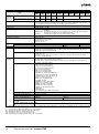
Function Specifications
Functions
Cycle Time
Management
Unit (I/O)
Management
A minimum cycle time can be set. (0.2 to 32,000 ms; Unit: 0.1 ms)
The minimum cycle time setting can be changed in MONITOR mode. *1
Cycle Time Monitoring
The cycle time is monitored.
(0.01 to 40,000 ms; Unit: 0.01 ms)
Background Processing
Instructions with long execution times can be executed over multiple cycles to
prevent fluctuations in the cycle time.
Basic I/O Units,
Special I/O Units,
and CPU Bus
Units
Basic I/O Units
Memory
Management
Memory Cards
*1.
*2.
Description
Minimum Cycle Time
I/O Refreshing
Cyclic Refreshing
Cyclic refreshing of Basic I/O Units, Special I/O Units, and CPU Bus Units
Immediate Refreshing I/O refreshing by immediate refreshing instructions
Refreshing by IORF
I/O refreshing by IORF instruction
Unit Recognition at Startup
The number of units recognized when the power is turned ON is displayed.
Input Response Time Setting
The input response times can be set for Basic I/O Units. The response time can
be increased to reduce the effects of chattering and noise at input contacts. The
response time can be decreased to enable detecting shorter input pulses.
Load OFF Function
All of the outputs on Basic I/O Units can be turned OFF when an error occurs in
RUN or MONITOR mode.
Basic I/O Unit Status Monitoring
Alarm information can be read from Basic I/O Units and the number of Units
recognized can be read.
Reading/writing data using instructions for
specific Units *1
Special instructions can be used to read/write required data for specific Units at
high speed.
Special I/O Units
and CPU Bus
Units
Unit Restart Bits to Restart Units
A Special I/O Unit or CPU Bus Unit can be restarted.
Synchronous Unit Operation *2
The start of processing for all the specified Units can be synchronized at a fixed
interval.
Maximum number of Units: 10 Units
(Only Units that support Synchronous Operation Mode can be used.)
Synchronous operation cycle: 0.5 to 10 ms (default: 2 ms)
Maximum number of words for synchronous data refreshing: 96 words (total of all
Units)
Configuration
Management
Automatic I/O Allocation at Startup
I/O words can be automatically allocated to the Basic I/O Units that are connected in
the PLC to start operation automatically without registering Units into I/O tables.
I/O Table Creation
The current unit configuration can be registered in I/O tables to prevent it from
being changed, to reserve words, and to set words.
Rack/Slot First Word Settings
The first words allocated to a Units on the Racks can be set.
Holding I/O Memory when Changing Operating Modes
The status of I/O memory can be held when the operating mode is changed or
power is turned ON. The forced-set/reset status can be held when the operating
mode is changed or power is turned ON.
File Memory
Files (such as program files, data files, and symbol table files) can be stored in
Memory Card, EM File Memory, or Comment Memory.
Built-in Flash Memory
The user program and Parameter Area can be backed up to an internal flash
memory when they are transferred to the CPU Unit.
EM File Function
Parts of the EM Area can be treated as file memory.
Storing Comments
I/O comments can be stored as symbol table files in a Memory Card, EM file
memory, or comment memory.
EM Configuration
EM Area can be set as trace memory or EM file memory.
Automatic File Transfer at Startup
A program file and parameter files can be read from a Memory Card when the
power is turned ON.
Program Replacement during PLC Operation
User programs can be transferred from a Memory Card to CPU Unit during operation.
Function for Reading and Writing Data from a Memory Card
Data in I/O memory in the CPU Unit can be written to a Memory Card in CSV/
TXT format. Data in CSV/TXT format in the Memory Card can be read to I/O
memory in the CPU Unit.
Supported only by the CJ2H CPU Units with unit version 1.1 or later and CJ2M CPU Units.
Supported only by the CJ2H CPU Units with unit version 1.1 or later.
Programmable Controllers SYSMAC CJ2
19
Functions
Communications
Peripheral (USB)
Port
Peripheral Bus
Serial Port *3
--Host Link commands or FINS commands placed between Host Link headers and
terminators can be sent from a host computer or PT to read/write I/O memory,
read/control the operating mode, and perform other operations for PLC.
No-protocol Communications
I/O instructions for communications ports (such as TXD/RXD instructions) can be
used for data transfer with peripheral devices such as bar code readers and printers.
NT Link Communications
I/O memory in the PLC can be allocated and directly linked to various PT
functions, including status control areas, status notification areas, touch switches,
lamps, memory tables, and other objects.
Peripheral Bus
Bus for communications with various kinds of Support Software running on a
personal computer. High-speed communications are supported.
Serial Gateway
This gateway enables receiving and automatically converting FINS to the CompoWay/F.
Serial PLC Links *4
Data is exchanged between CPU Units using serial ports without
communications programming. PTs set to the 1:N NT Link protocol can be
included in the network.
100Base-TX/10Base-T
Protocols: TCP/IP, UDP, ARP, ICMP (ping only), BOOTP
Applications: FINS, CIP, SNTP, DNS (Client), FTP (Server)
CIP
Communicatio
ns Service
Tag Data Links
Programless cyclic data exchanges with the devices on the EtherNet/IP network.
Message Communications
Any CIP commands can be received from the devices on the EtherNet/IP network.
FINS
Communicatio
ns Service
Message Communications
Any FINS commands can be transferred with the devices on the EtherNet/IP
network.
Scheduled Interrupts
*3.
*4.
*5.
*6.
*7.
20
Tasks can be executed at a specified interval
Resetting and restarting with MSKS(690) *6
When MSKS(690) is executed, the internal timer is restarted and the time to first
interrupt is set to a fixed value.
Reading present value of internal timer with MSKS(690)
*6
MSKS(690) can be used to read the time that has elapsed until the schedule
interrupt is started or since the previous scheduled interrupt.
Power OFF Interrupts
Clock
Bus for communications with various kinds of Support Software running on a
personal computer. High-speed communications are supported.
Host Link (SYSWAY) Communications
EtherNet/IP Port *5
Interrupt
Description
---
A task can be executed when CPU Unit's power turns OFF.
I/O Interrupt Tasks
A task can be executed when an input signal is input to an Interrupt Input Unit.
External Interrupt Tasks
A task can be executed when interrupts are requested from a Special I/O Unit or
a CPU Bus Unit.
High-speed Interrupt Function *7
Improves performance for executing interrupt tasks with certain restrictions.
Clock Function
Clock data is stored in memory.
Accuracy (Accuracy depends on the temperature.)
Ambient temperature of 55°C: −3.5 to +0.5 min error per month
Ambient temperature of 25°C: −1.5 to +1.5 min error per month
Ambient temperature of 0°C: −3 to +1 min error per month
Operation Start Time Storage
The time when operating mode was last changed to RUN mode or MONITOR
mode is stored.
Operation Stop Time Storage
The last time a fatal error occurred or the last time the operating mode was
changed to PROGRAM mode is stored.
Startup Time Storage
The time when the power was turned ON is stored.
Power Interruption Time Storage
The time when the power is turned OFF is stored.
Total Power ON Time Calculation
The total time that the PLC has been ON is stored in increments of 10 hours.
Power ON Clock Data Storage
A history of the times when the power was turned ON is stored.
User Program Overwritten Time Storage
The time that the user program was last overwritten is stored.
Parameter Date Storage
The time when the Parameter Area was overwritten is stored.
A Serial Option Board is required to use a serial port for the CJ2M-CPU3@ CJ2M CPU Unit.
A Serial Option Board is required to use the CJ2M-CPU3@ CJ2M CPU Unit in Serial PLC Links.
Supported only by the CJ2H-CPU6@-EIP and CJ2M-CPU3@.
Supported only by the CJ2M CPU Units.
Supported only by the CJ2H CPU Units with unit version 1.1 or later.
Programmable Controllers SYSMAC CJ2
Functions
Power Supply
Management
Description
Memory Protection
Holding Area data, DM Area data, EM Area data, Counter Completion Flags, and
counter present values are held even when power is turned OFF. CIO Area, Work
Area, some Auxiliary Area data, and Timer Completion Flags, timer present
values, index registers, and data registers can be protected by turning ON the
IOM Hold Bit in the Auxiliary Area, and by also setting the IOM Hold Bit to “Hold”
in the PLC Setup.
Power OFF Detection Time Setting
The detection time for power interruptions can be set.
AC power supply: 10 to 25 ms (variable)
DC power supply: 2 to 5 ms (CJ1W-PD022) or 2 to 20 ms (CJ1W-PD025)
Power OFF Detection Delay Time
The detection of power interruptions can be delayed: 0 to 10 ms
(Not supported by the CJ1W-PD022.)
Number of Power Interruptions Counter
The number of times power has been interrupted is counted.
Function Blocks
Debugging
Standard programming can be encapsulated as function blocks.
Languages in Function Block Definitions
Ladder programming or structured text
Online Editing
The program can be changed during operation (in MONITOR or PROGRAM
mode), except for block programming areas.
Force-Set/Reset
Specified bits can be set or reset.
A parameter can be set to enable force-setting/resetting bits in EM Area banks.
Force-setting/resetting is enabled for the specified bank and all the banks after it.
*8
Self-diagnosis
and Restoration
Differentiate Monitoring
ON/OFF changes in specified bits can be monitored.
Data Tracing
The specified I/O memory data can be stored in the trace memory in the CPU
Unit. The triggers can be set.
Continuous Tracing
The trace data can be uploaded during data tracing using CX-Programmer, which
enables continuously logging the data by constantly uploading the trace data
(trace data uploading during tracing).
Automatically starting tracing when operation starts
Data tracing can be automatically started when operation is started (i.e., when
the operating mode is changed from PROGRAM mode to MONITOR or RUN
mode).
Storing Location of Error when an Error Occurs
The location and task number where execution stopped for a program error is
recorded.
Program Check
The programs can be checked for items such as no END instruction and FALS/
FAL errors at startup.
Error Log
A function is provided to store predefined error codes in CPU Unit, error
information, and time at which the error occurred.
CPU Error Detection
CPU Unit WDT errors are detected.
User-defined Failure Diagnosis
Errors can be generated for user-specified conditions: Non-fatal errors (FAL) and
fatal errors (FALS).
Program section time diagnosis and program section logic diagnosis are
supported (FPD instruction).
Load OFF Function
This function turns OFF all outputs from Output Units when an error occurs.
RUN Output
The RUN output from the CJ1W-PA205R turns ON while CPU Unit is in RUN
mode or MONITOR mode.
Basic I/O Load Short-circuit Detection
This function provides alarm information from Basic I/O Units that have load
short-circuit protection.
Failure Point Detection
The time and logic of an instruction block can be analyzes using the FPD
instruction.
CPU Standby Detection
This function indicates when the CPU Unit is on standby because all Special I/O
Units and CPU Bus Units have not been recognized at the startup in RUN or
MONITOR mode.
Non-fatal Error Detection
System FAL Error Detection
(User-defined non-fatal error)
This function generates a non-fatal (FAL) error when the user-defined conditions
are met in program.
Duplicated Refreshing Error
Detection
This function detects an error when an immediate refreshing Instruction in an
interrupt task is competing with I/O refreshing of a cyclic task.
Basic I/O Unit Error Detection
This function detects the errors in Basic I/O Units.
Backup Memory Error Detection
This function detects errors in the memory backup of the user programs and
parameter area (backup memory).
PLC Setup Error Detection
This function detects setting errors in the PLC Setup.
CPU Bus Unit Error Detection
This function detects an error when there is an error in data exchange between
the CPU Unit and a CPU Bus Unit.
Special I/O Unit Error Detection
This function detects an error when there is an error in data exchange between
the CPU Unit and a Special I/O Unit.
Tag Memory Error Detection *9
This function detects errors in tag memory.
Battery Error Detection
This function detects an error when a battery is not connected to the CPU Unit or
when the battery voltage drops.
CPU Bus Unit Setting Error
Detection
This function detects an error when the model of a CPU Bus Unit in the
registered I/O tables does not agree with the model that is actually mounted in
the PLC.
Special I/O Unit Setting Error
Detection
This function detects an error when the model of a Special I/O Unit in the
registered I/O tables does not agree with the model of Unit that is actually
mounted.
Option Board Error Detection *10
This function detects the errors in Serial Option Board mounting status.
*8. Supported only by CJ2H CPU Units with unit version 1.2 or later and CJ2M CPU Units.
*9. Supported only by CJ2H-CPU6@-EIP and CJ2H-CPU3@.
*10. Supported only by CJ2M-CPU3@.
Programmable Controllers SYSMAC CJ2
21
Functions
Self-diagnosis
and Restoration
(Continued from
previous page)
Maintenance
Fatal Error Detection
Description
Memory Error Detection
This function detects errors that occur in memory of the CPU Unit.
I/O Bus Error Detection
This function detects when an error occurs in data transfers between the Units
mounted in Rack slots and the CPU Unit and detects when the End Cover is not
connected to the CPU Rack or an Expansion Rack.
Unit/Rack Number Duplication
Error
This function detects an error when the same unit number is set for two or more
Units, the same word is allocated to two or more Basic I/O Units, or the same
rack number is set for two or more Racks.
Too Many I/O Points Error
Detection
This function detects an error when the total number of I/O points set in the I/O
tables or the number of Units per Rack exceeds the specified range.
I/O Setting Error Detection
The registered I/O tables are used to detect errors if the number of Units in the
registered I/O tables does not agree with the actual number of Units that are
connected or an Interrupt Unit has been connected in the wrong position, i.e., not
in the following slots.
• CJ2H-CPU6@-EIP: Slots 0 to 3
• CJ2H-CPU6@: Slots 0 to 4
• CJ2M-CPU3@: Slots 0 to 4
• CJ2M-CPU1@: Slots 0 to 4
Program Error Detection
This function detects errors in programs.
Instruction
Processing Error
Detection
This function detects an error when the given data value is invalid when
executing an instruction, or execution of instruction between tasks was
attempted.
Indirect DM/EM BCD
Error Detection
This function detects an error when an indirect DM/EM address in BCD mode is
not BCD.
Illegal Area Access
Error Detection
This function detects an error when an attempt is made to access an illegal area
with an instruction operand.
No END Error
Detection
This function detects an error when there is no END instruction at the end of the
program.
Task Error Detection
This function detects an error when there are no tasks that can be executed in a
cycle, there is no program for a task, or the execution condition for an interrupt
task was met but there is no interrupt task with the specified number.
Differentiation
Overflow Error
Detection
This function detects an error when too many differentiated instructions are
entered or deleted during online editing (131,072 times or more).
Invalid Instruction
Error Detection
This function detects an error when an attempt is made to execute an instruction
that is not defined in the system.
User Program Area
Overflow Error
Detection
This function detects an error when instruction data is stored after the last
address in user program area.
Cycle Time Exceeded Error
Detection
This function monitors the cycle time (10 to 40,000 ms) and stops the operation
when the set value is exceeded.
System FALS Error Detection
(User-defined Fatal Error)
This function generates a fatal (FALS) error when the user-defined conditions are
met in program.
Version Error Detection
This function detects an error when a user program includes a function that is not
supported by the current unit version.
Memory Card Transfer Error
Detection
This function detects an error when the automatic file transfer from Memory Card
fails at startup.
Memory Self-restoration Function
This function performs a parity check on the user program area and selfrestoration data. *11
Simple Backup Function
This function collectively backs up the data in CPU Unit (user programs,
parameters, and I/O memory) and internal backup data in the I/O Units.
Unsolicited Communications
A function that allows the PLC to use Network Communications Instruction to
send required FINS commands to a computer connected via a Host Link
Remote Programming and Monitoring
Host Link communications can be used for remote programming and remote
monitoring through a Controller Link, Ethernet, DeviceNet, or SYSMAC LINK
Network. Communications across network layers can be performed.
Controller Link or Ethernet: 8 layers
DeviceNet or SYSMAC LINK: 3 layers
Automatic Online Connection via
Network
Security
Direct Serial
Connection
This function enables automatically connecting to the PLC online when the CXProgrammer is directly connected by a serial connection (peripheral (USB) port
or serial port).
Via Networks
This function enables connecting the CX-Programmer online to a PLC that is
connected via an EtherNet/IP network.
Read Protection using Password
This function protects reading and displaying programs and tasks using
passwords.
Write protection: Set using the DIP switch.
Read protection: Set a password using the CX-Programmer.
FINS Write Protection
This function prohibits writing by using FINS commands sent over the network.
Unit Name Function
This function allows the users to give any names to the Units. Names are verified
at online connection to prevent wrong connection
Hardware ID Using Lot Numbers
This function sets operation protection by identifying hardware using the user
programs according to lot numbers stored in the Auxiliary Area.
*11. Supported only by CJ2H CPU Units.
22
Programmable Controllers SYSMAC CJ2
■ Unit Versions
Units
CJ2H CPU Unit
Models
CJ2H-CPU6@-EIP
Unit Version
Unit version 1.0 (Built-in EtherNet/IP section: Unit version 2.0)
Unit version 1.1 (Built-in EtherNet/IP section: Unit version 2.0)
Unit version 1.2 (Built-in EtherNet/IP section: Unit version 2.0)
Unit version 1.3 (Built-in EtherNet/IP section: Unit version 2.0)
CJ2H-CPU6@
Unit version 1.1
Unit version 1.2
Unit version 1.3
CJ2M CPU Unit
CJ2M-CPU3@
Unit version 1.0 (Built-in EtherNet/IP section: Unit version 2.0)
Unit version 2.0 (Built-in EtherNet/IP section: Unit version 2.0)
CJ2M-CPU1@
Unit version 1.0
Unit version 2.0
■ Unit Versions and Programming Devices
The following tables show the relationship between unit versions and CX-Programmer versions.
Required Programming Device
CPU Unit
CJ2H
CJ2M
*1.
*2.
*3.
Functions
CX-Programmer
Ver.7.1 or
lower
Ver.8.0
Ver.8.2 or
higher
Ver.9.0
Ver.9.1 or Ver.9.12 or
higher
higher
CJ2H-CPU6@-EIP
Unit version 1.0
Functions for unit version 1.0
---
OK
OK
OK
OK
OK
CJ2H-CPU6@-EIP
Unit version 1.1
Functions added
for unit version 1.1
Using new functions
---
---
OK *2
OK
OK
OK
Not using new
functions
---
OK *1
OK
OK
OK
OK
CJ2H-CPU6@
Unit version 1.1
Functions added
for unit version 1.1
Using new functions
---
---
OK *2
OK
OK
OK
Not using new
functions
---
---
OK
OK
OK
OK
CJ2H-CPU6@-EIP
Unit version 1.2
Functions added
for unit version 1.2
Using new functions
---
---
---
OK
OK
OK
Not using new
functions
---
OK *1
OK *1
OK
OK
OK
CJ2H-CPU6@
Unit version 1.2
Functions added
for unit version 1.2
Using new functions
---
---
---
OK
OK
OK
Not using new
functions
---
OK *1
OK *1
OK
OK
OK
CJ2H-CPU6@-EIP
Unit version 1.3
Functions added
for unit version 1.3
Using new functions
---
---
---
---
OK
OK
Not using new
functions
---
OK *1
OK *1
OK
OK
OK
CJ2H-CPU6@
Unit version 1.3
Functions added
for unit version 1.3
Using new functions
---
---
---
---
OK
OK
Not using new
functions
---
OK *1
OK *1
OK
OK
OK
CJ2M-CPU@@
Unit version 1.0
Functions for unit version 1.0
---
---
---
---
OK
OK
CJ2M-CPU@@
Unit version 2.0
Functions added
for unit version 2.0
Using new functions
---
---
---
---
---
OK
Not using new
functions
---
---
---
---
OK *1
OK
Programming
Console
--- *3
It is not necessary to upgrade the version of the CX-Programmer if functionality that was enhanced for the upgrade of the CPU Unit will not be used.
CX-Programmer version 8.2 or higher is required to use the functions added for unit version 1.1. The high-speed interrupt function and changing the minimum
cycle time setting in MONITOR mode, however, are also supported by CX-Programmer version 8.02.
A Programming Console cannot be used with a CJ2 CPU Unit.
Programmable Controllers SYSMAC CJ2
23
Specifications for Pulse I/O Functions
The following functions of CJ2M can be used by installing one or two Pulse I/O Module. Each module has 10 high-speed inputs and 6
high-speed outputs. Pulse I/O Modules can be installed on CJ2M CPU Units with Unit Version 2.0 or Later.
• The inputs can be used as general-purpose inputs, interrupt inputs, quick-response inputs, high-speed counters, or origin search
inputs.
• The outputs can be used as general-purpose outputs, pulse outputs, origin search outputs, or PWM outputs.
One Pulse I/O Module can be mounted
Two Pulse I/O Modules can be mounted
CJ2M CPU Unit
(Standard or Simple Model)
Pulse I/O Module
Connected
CJ2M CPU Unit
(Standard or Simple Model)
Pulse I/O Module
Connected
Connected
Note: The Pulse I/O Module closest
to the CPU Unit is Pulse I/O
Module 0 and the other one is
Pulse I/O Module 1.
Pulse I/O Module 0
Pulse I/O Module 1
Pulse I/O Module 0
■Performance Specifications
Item
Description
Model of Pulse I/O Modules
CJ2M-MD211 (Sinking-type)
CJ2M-MD212 (Sourcing-type )
External interface
40-pin MIL connector
Pulse Inputs
Can be used as normal inputs, interrupt inputs, quick-response inputs, or high-speed counter inputs. (Function of each input must be
selected in the PLC Setup.)
Input method: Line-driver input or 24-VDC input (selected by via wiring)
Normal Inputs
20 max. (10 per Pulse I/O Module)
Input constants: Set in the PLC Setup (0, 0.5, 1, 2, 4, 8, 16, or 32 ms). Default: 8 ms
Interrupt inputs and quick-response
inputs
8 max. (4 per Pulse I/O Module)
Input signal minimum ON pulse width: 30 µs
High-speed counter inputs
4 max. (2 per Pulse I/O Module)
Input method: Differential-phase (×4) pulses, pulse + direction, up/down pulses, or increment pulse
Maximum response frequency: 50 kHz for differential phases or 100 kHz for single phase
Counting mode: Linear mode or circular (ring) mode
Count value: 32 bits
Counter reset: Phase Z + software reset or software reset
Control method: Target-value comparison or range comparison
Gate function: Supported
Pulse
I/O
Pulse Outputs
Can be used as normal outputs, pulse outputs, or PWM outputs. (Function of each output must be selected in the PLC Setup.)
Output method: Sinking or sourcing transistor outputs (The method is determined by Pulse I/O Module model.)
Normal Outputs
12 max. (6 per Pulse I/O Module)
Pulse Outputs
4 max. (2 per Pulse I/O Module)
Output method: CW/CCW or pulse + direction (The method is determined by the I/O wiring and the instructions used in the ladder program.)
Output frequency: 1 pps to 100 kpps (in increments of 1 pps)
Output Mode: Continuous mode (for speed control) or independent mode (for position control)
Output pulses: Relative coordinates: 0000 0000 to 7FFF FFFF hex (0 to 2,147,483,647 pulses)
Absolute coordinates: 8000 0000 to 7FFF FFFF hex (−2,147,483,648 to 2,147,483,647)
Acceleration/deceleration curves: Linear or S-curve
Origin search function: Supported
PWM Outputs
4 max. (2 per Pulse I/O Module)
Output frequency: 0.1 to 6,553.5 Hz (in 0.1-Hz increments) or 1 to 32,800 Hz (in 1-Hz increments)
Duty ratio: 0.0% to 100.0% (in 0.1% increments)
■Function Specifications
Functions
Pulse Input
Functions
Pulse I/O
Functions
Pulse
Output
Functions
Input signals are read during I/O refreshing and stored in I/O memory.
Interrupt Inputs
An interrupt task can be started when an input signal turns ON or turns OFF.
Quick-response Inputs
Input signals that are shorter than the cycle time are read and stored in I/O memory.
High-speed Counter Inputs
High-speed pulse signals are counted. Interrupt tasks can also be started.
Normal Outputs
The status of I/O memory is output during I/O refreshing.
Pulse Outputs
A pulse signal is output with the specified frequency and number of pulses at a fixed duty ratio (50%).
PWM Outputs
A pulse signal is output at the specified duty ratio.
Origin Searches
The origin point of the machine is determined according to the specified origin search parameters while actually outputting pulses
and using the origin and origin proximity input signals as conditions. (Pulse inputs and outputs are also used for this function.)
Input Interrupt Function
A task is started for an interrupt input from a Pulse I/O Module or for a high-speed counter input.
Input Interrupts
Interrupt tasks are executed when the interrupt input turns ON or turns OFF.
Direct Mode: An interrupt task is executed each time an input signal changes.
Counter Mode: Changes in the input signal are counted up or down and the interrupt task is executed when the counter counts out.
(The maximum response frequency is 3 kHz.)
High-speed Counter Interrupts
An interrupt task is executed when preset comparison conditions for a high-speed counter are met.
Target-value comparison: The interrupt task is executed when the count matches a specified value.
Range comparison: The interrupt task is executed when the count enters or leaves a specified range of values.
Interrupt
24
Description
Normal Inputs
Programmable Controllers SYSMAC CJ2
■Allocating Functions to I/O signals
Pulse I/O Module 0 (on the right)
Terminal symbol
Address
IN 00
Bit
IN 02
IN 03
IN 04
IN 05
IN 06
IN 07
IN 08
IN 09
OUT 00 OUT 01 OUT 02 OUT 03 OUT 04 OUT 05
2961
0
1
2
3
4
5
6
7
8
9
Normal inputs
Normal
input 0
Normal
input 1
Normal
input 2
Normal
input 3
Normal
input 4
Normal
input 5
Normal
input 6
Normal
input 7
Normal
input 8
Normal
input 9
---
---
---
---
---
---
Interrupt inputs
(Direct Mode/
Counter Mode)
Interrupt
input 0
Interrupt
input 1
Interrupt
input 2
Interrupt
input 3
---
---
---
---
---
---
---
---
---
---
---
---
Quick response
inputs
Quick
Quick
Quick
Quick
response response response response
input 0
input 1
input 2
input 3
---
---
---
---
---
---
---
---
---
---
---
---
---
---
Highspeed
counter 1
(phase-A,
increment, or
count
input)
Highspeed
counter 1
(phase-B,
decrement, or
direction
input)
Highspeed
counter 0
(phase-A,
increment, or
count
input)
Highspeed
counter 0
(phase-B,
decrement, or
direction
input)
---
---
---
---
---
---
Inputs
Highspeed
counter 1
(phaseZ/reset)
Highspeed
counter 0
(phaseZ/reset)
0
1
2
3
4
5
High-speed
counters
---
---
Normal outputs
---
---
---
---
---
---
---
---
---
---
Normal Normal Normal Normal Normal Normal
output 0 output 1 output 2 output 3 output 4 output 5
---
---
---
---
---
---
---
---
---
---
Pulse
Pulse
Pulse
Pulse
output 0 output 0 output 1 output 1
(CW)
(CCW) (CW)
(CCW)
---
---
---
---
---
---
---
---
---
---
---
---
Pulse
Pulse
Pulse
Pulse
output 0 output 1 output 0 output 1
pulse)
(pulse) (direction) (direction)
---
---
---
---
---
---
---
---
---
---
---
---
Origin
search 0
(Origin
Input
Signal)
Origin
search 0
(Origin
Proximity Input
Signal)
Origin
search 1
(Origin
Input
Signal)
Origin
search 1
(Origin
Proximity Input
Signal)
Origin
search 0
(Positioning
Completed
Signal)
Origin
search 1
(Positioning
Completed
Signal)
IN 12
IN 13
IN 14
IN 15
CW/CCW
outputs
Outputs
IN 01
2960
Pulse +
Pulse
direction
outoutputs
puts
Variable
duty
ratio
outputs
Origin search
---
---
---
---
IN 16
IN 17
IN 18
IN 19
---
---
---
---
---
---
---
---
PWM
PWM
output 0 output 1
Pulse
output 0
error
counter
reset
output
(operatio
n modes
1 and 2)
Pulse
output 1
error
counter
reset
output
(operatio
n modes
1 and 2)
Pulse I/O Module 1 (on the left)
Terminal symbol
Address
Bit
IN 11
OUT 10 OUT 11 OUT 12 OUT 13 OUT 14 OUT 15
2963
0
1
2
3
4
Normal inputs
Normal
input 10
Normal
input 11
Normal
input 12
Normal
input 13
Normal Normal Normal Normal Normal Normal
input 14 input 15 input 16 input 17 input 18 input 19
Interrupt inputs
(Direct Mode/
Counter Mode)
Interrupt
input 4
Interrupt
input 5
Interrupt
input 6
Interrupt
input 7
Quick response
inputs
Quick
Quick
Quick
Quick
response response response response
input 4
input 5
input 6
input 7
Inputs
Highspeed
counter 3
(phaseZ/reset)
Highspeed
counter 2
(phaseZ/reset)
5
6
7
8
9
0
1
2
3
4
5
---
---
---
---
---
---
---
---
---
---
---
---
---
---
---
---
---
---
---
---
---
---
---
---
---
---
---
---
---
---
---
---
Highspeed
counter 3
(phase-A,
increment, or
count
input)
Highspeed
counter 3
(phase-B,
decrement, or
direction
input)
Highspeed
counter 2
(phase-A,
increment, or
count
input)
Highspeed
counter 2
(phase-B,
decrement, or
direction
input)
---
---
---
---
---
---
High-speed
counters
---
---
Normal outputs
---
---
---
---
---
---
---
---
---
---
Normal Normal Normal Normal Normal Normal
output 6 output 7 output 8 output 9 output 10 output 11
---
---
---
---
---
---
---
---
---
---
Pulse
Pulse
Pulse
Pulse
output 2 output 2 output 3 output 3
(CW)
(CCW) (CW)
(CCW)
---
---
---
---
---
---
---
---
---
---
---
---
Pulse
Pulse
Pulse
Pulse
output 2 output 3 output 2 output 3
pulse)
(pulse) (direction) (direction)
---
---
CW/CCW
outputs
Outputs
IN 10
2962
Pulse +
Pulse
direction
outoutputs
puts
Variable
duty
ratio
outputs
Origin search
---
---
---
---
---
---
Origin
search 2
(Origin
Input
Signal)
Origin
search 2
(Origin
Proximity Input
Signal)
Origin
search 3
(Origin
Input
Signal)
Origin
search 3
(Origin
Proximity Input
Signal)
Origin
search 2
(Positioning
Completed
Signal)
Origin
search 3
(Positioning
Completed
Signal)
---
---
---
---
---
---
---
---
---
---
---
---
---
---
---
---
Programmable Controllers SYSMAC CJ2
PWM
PWM
output 2 output 3
Pulse
output 2
error
counter
reset
output
(operatio
n modes
1 and 2)
Pulse
output 3
error
counter
reset
output
(operatio
n modes
1 and 2)
25
■Specifications of Pulse Input Functions
● Interrupt Inputs
Item
Number of interrupt inputs
Direct Mode
Counter Mode
Max. 8 inputs
Allocated bit
CIO 2960 and CIO 2962, bits 00 to 03
Interrupt detection method
ON-to-OFF or OFF-to-ON transitions
Interrupt task numbers
140 to 147 (fixed)
Counting method
---
Incrimenting or decrementing
(Set with the MSKS(690) instruction.)
Counting range
---
0001 to FFFF hex (16 bits)
(Set in A532 to A535 and A544 to A547.)
Response frequency
---
Single-phase: 3 kHz x 8 inputs
Storage locations for PVs for interrupt inputs
in Counter Mode
---
A536 to A539 and A548 to A551
● Quick-response inputs
Item
Specifications
Number of Quick-response inputs
Max. 8 inputs
Quick-response inputs
Signals that are shorter than the cycle time are latched for one PLC cycle, so they can be detected in the PLC
program. Minimum detectable pulse width is 30 µs.
● High-speed Counter Inputs
Item
Description
Number of High-speed Counter Inputs
Max. 4 inputs
Pulse input method (counting mode)
Incremental pulse inputs
Differential phase input (4×) Up/down inputs
Pulse + direction inputs
Input signals
Increment pulse
Phase A
Up pulse
Pulse
---
Phase B
Down pulse
Direction
---
Phase Z
Reset
Reset
Frequency and number of high-speed
counters
100 kHz, 2 inputs × 2 I/O
Modules
50 kHz, 2 inputs × 2 I/O
Modules
100 kHz, 2 inputs
× 2 I/O Modules
100 kHz, 2 inputs
× 2 I/O Modules
Counting mode
Linear mode or ring mode
Count value
Linear mode:
Ring mode:
High-speed counter PV storage locations
High-speed counter 0: A271 (upper 4 digits) and A270 (lower 4 digits)
High-speed counter 1: A273 (upper 4 digits) and A272 (lower 4 digits)
High-speed counter 2: A317 (upper 4 digits) and A316 (lower 4 digits)
High-speed counter 3: A319 (upper 4 digits) and A318 (lower 4 digits)
Refreshed during overseeing processing. Use PRV(881) to read the most recent PVs.
Data format: 8 digit hexadecimal
• Linear mode:
• Ring mode:
Control method
8000 0000 to 7FFF FFFF hex
0000 0000 to FFFF FFFF hex (for increment pulse)
0000 0000 to Max. ring value
Target value comparison
Up to 48 target values and corresponding interrupt task numbers can be registered.
Range Comparison
Up to 8 or up to 32 ranges can be registered, with a separate upper limit, lower limit, and interrupt task number for
each range.
Counter reset method
26
8000 0000 to 7FFF FFFF hex
0000 0000 to FFFF FFFF hex (for increment pulse)
0000 0000 to Max. ring value
• Phase-Z + Software reset
The counter is reset when the phase-Z input goes ON while the Reset Bit (A531.00 to A531.03) is ON.
• Software reset
The counter is reset when the Reset Bit (A531.00 to A531.03) is turned ON.
Operation can be set to stop or continue the comparison operation when the high-speed counter is reset.
Programmable Controllers SYSMAC CJ2
■Specifications of Pulse Output Functions
● Position Control and Speed Control
Item
Specifications
Number of Pulse Outputs
Max. 4 outputs (Pulse Output 00 to 03)
Output mode
Continuous mode (for speed control) or independent mode (for position control)
Positioning (independent mode) instructions PULS (886) and SPED (885), PULS (886) and ACC (888), or PULS2 (887) instruction
Speed control (continuous mode)
instructions
SPED( 885) and ACC (888) instructions
Origin (origin search and origin return)
instructions
ORG (889) instruction
Interrupt feeding instruction
IFEED (892) instruction
Output frequency
1 pps to 100 kpps (1 pps units), two pulse outputs × 2 Pulse I/O Modules
Frequency acceleration and deceleration
rates
Set in increments of 1 pps for acceleration/deceleration rates from 1 to 65,535 pps (every 4 ms).
The acceleration and deceleration rates can be set independently only with the PLS2 (887) instruction.
Changing SVs during instruction execution
The target frequency, acceleration/deceleration rate, and target position can be changed.
Pulse output method
CW/CCW or pulse + direction
Number of output pulses
Relative coordinates: 0000 0000 to 7FFF FFFF hex (Accelerating or decelerating in either direction: 2,147,483,647)
Absolute coordinates: 8000 0000 to 7FFF FFFF hex (−2,147,483,648 to 2,147,483,647)
Relative/absolute coordinate specifications
for pulse output PVs
Absolute coordinates are specified automatically when the origin location has been defined by changing the pulse
output PV with the INI (880) instruction or performing an origin search with the ORG(889) instruction. Relative
coordinates must be used when the origin is undefined.
Relative pulse/absolute pulse specifications
The pulse type can be specified with an operand in the PULS (886) or PLS2 (887) instruction.
Absolute pulses can be used when absolute coordinates are specified for the pulse output PV, i.e. the origin location
has been defined. Absolute pulse cannot be used when relative coordinates are specified, i.e., when the origin
location is undefined. An instruction error will occur.
Pulse output PV's storage location
The following Auxiliary Area words contain the pulse output PVs
Pulse output 0: A277 (leftmost 4 digits) and A276 (rightmost 4 digits)
Pulse output 1: A279 (leftmost 4 digits) and A278 (rightmost 4 digits)
Pulse output 2: A323 (leftmost 4 digits) and A322 (rightmost 4 digits)
Pulse output 3: A325 (leftmost 4 digits) and A324 (rightmost 4 digits)
The PVs are refreshed during regular I/O refreshing.
● Variable-duty Pulse Outputs (PWM)
Item
Specifications
Number of PWM Outputs
Max. 4 outputs (PWM Output 00 to 03)
Duty ratio
0.0% to 100.0% in 0.1% increments
Frequency
0.1 Hz to 6,553.5 Hz (Set in 0.1-Hz increments.)
1 Hz to 32,800 Hz (Set in 1-Hz increments.)
Output mode
Continuous Mode
Instruction
PWM (891) instruction
Programmable Controllers SYSMAC CJ2
27
■Specifications of Pulse I/O Modules
● Input Specifications (IN00 to IN09/IN10 to IN19)
Normal Inputs
IN00 to IN05 and
IN10 to IN15
Inputs
Input form
IN06 to IN09 and
IN16 to IN19
IN00 to IN05 and
IN10 to IN15
24-VDC inputs
Input current
6.0 mA typical
Input voltage range
24 VDC +10%/−15%
Input impedance
3.6 kΩ
Number of circuits
1 common, 1 circuit
IN06 to IN09 and
IN16 to IN19
Line driver inputs
5.5 mA typical
13 mA typical
10 mA typical
RS-422A or RS-422 line driver (conforming to AM26LS31),
Power supply voltage of 5 V ± 5%
4.0 kΩ
---
ON voltage/current
17.4 VDC min., 3 mA min.
---
OFF voltage/current
1 mA max. at 5 VDC max.
---
ON response time
8 ms max. (The input time constant can be set to 0, 0.5, 1, 2, 4, 8, 16, or 32 ms in the PLC Setup.)
OFF response time
8 ms max. (The input time constant can be set to 0, 0.5, 1, 2, 4, 8, 16, or 32 ms in the PLC Setup.)
Input Circuit Configuration
Item
Specifications
Input
IN00 to IN05/IN10 to IN15
IN06 to IN09/IN16 to IN19
24 V
LD+
LD+
Internal circuits
24 V
Interrupt Input and Quick-response Input Specifications (IN00 to IN03 and IN10 to IN13)
Item
Specifications
ON response time
30 µs max.
OFF response time
150 µs max.
Response pulse
30 µs min.
150 µs min.
ON
OFF
28
Programmable Controllers SYSMAC CJ2
Internal circuits
Circuit configuration
High-speed Counter Input Specifications (IN06 to IN09 and IN16 to IN19)
24-VDC input
Line driver input
Phase-A/Phase-B encoder input, Single-phase
60-kHz pulse input with 50% duty ratio
Encoder input phase A or B, single-phase
60-kHz pulse input with 50% duty ratio
Rise time and fall time: 3.0 µs max.
16.6 µs min.
8.3 µs min.
8.3 µs min.
ON
ON
50%
50%
OFF
OFF
Set to 60 kHz
Phase-A/Phase-B encoder inputs, Differential
phases, 30 kHz
Phase-A/Phase-B encoder inputs, Differential
phases, 30 kHz
Changes in phases A and B must be
separated by at least 4.0 µs.
Changes in phases A and B must be separated by at least
4.0 µs.
33.3 µs min.
ON
ON
50%
50%
OFF
ON
OFF
ON
50%
50%
OFF
OFF
T1
T2
T3
T4
T1
T2
T3
T4
T1, T2, T3, T4: 4.0 µs min.
Single-phase 100-kHz pulse input with
50% duty ratio
Phase-A/Phase-B encoder input, Single-phase
100-kHz pulse input with 50% duty ratio
Rise time and fall time: 2.5 µs max.
10.0 µs min.
ON
5.0 µs min.
ON
5.0 µs min.
50%
50%
OFF
OFF
2.5 µs max.
Set to 100 kHz
2.5 µs max.
Differential-phase 50-kHz pulse input
Phase-A/Phase-B encoder inputs, Differential
phases, 50 kHz
Changes in phases A and B must be separated
by at least 2.5 µs.
Changes in phases A and B must be
separated by at least 2.5 µs.
ON
ON
50%
50%
OFF
ON
OFF
ON
50%
50%
OFF
OFF
T1
T1
T2
T3
Encoder input phase Z (IN02/IN03 or IN12/IN13)
ON
150 µs min.
50%
30 µs min.
OFF
T3
T4
Encoder input phase Z (IN02/IN03 or IN12/IN13)
Maintain an ON time of 30 µs min.
and an OFF time of 150 µs min.
30 µs min.
150 µs min.
Maintain an ON time of 30 µs min.
and an OFF time of 150 µs min.
Phase Z/reset input
T2
T4
ON
50%
OFF
Programmable Controllers SYSMAC CJ2
29
Output Specifications (OUT00 to OUT05 and OUT10 to OUT15)
Item
Specifications
Output Specifications
Sinking-type (CJ2M-MD211)
Rated voltage
5 to 24 VDC
Allowable voltage range
4.75 to 26.4 VDC
Maximum switching
current
0.3 A/output, 1.8 A/Unit
Number of circuits
6 outputs (6 outputs/common)
Maximum inrush current
3.0 A/output, 10 ms max.
Leakage current
0.1 mA max.
Residual voltage
0.6 V max.
ON response time
0.1 ms max.
Sourcing-type (CJ2M-MD212)
2.0 A/output, 10 ms max.
OFF response time
0.1 ms max.
Fuse
None
External supply power
(power supply input for
outputs)
10.2 to 26.4 VDC, 20 mA min.
Circuit configuration
COM
+V
Internal circuits
Internal circuits
Rated
voltage
circuit
OUT
Isolation
circuit
OUT
Isolation
circuit
Rated
voltage
circuit
COM
−V
Pulse Outputs (OUT00 to OUT03 and OUT10 to OUT13)
Item
Specifications
Output Specifications
Sinking-type (CJ2M-MD211)
Rated voltage
5 to 24 VDC
Allowable voltage range
4.75 to 26.4 VDC
Maximum switching
capacity
30 mA
Minimum switching
capacity
7 mA
Maximum output
frequency
100 kHz
Output waveform
OFF
ON
Sourcing-type (CJ2M-MD212)
ON
90%
10%
OFF
2 µs min.
4 µs min.
90%
10%
4 µs min.
2 µs min.
PWM Outputs (OUT04, OUT05, OUT14, and OUT15)
Item
Specifications
Output Specifications
Sinking-type (CJ2M-MD211)
Rated voltage
5 to 24 VDC
Allowable voltage range
4.75 to 26.4 VDC
Maximum switching
capacity
6.5535 kHz or less: 300 mA, 6.5535 to 32.8 kHz: 100 mA
Maximum output
frequency
32,800 Hz
PWM output accuracy
(for ON pulse width of
2 µs or longer)
ON duty at 6.5535 kHz or less: -0.2% to +1%,
ON duty at 32.8 kHz: -1% to +5%
(at switching current of 30 mA)
Output waveform
Sourcing-type (CJ2M-MD212)
ON duty at 6.5535 kHz or less: ±0.5%,
ON duty at 32.8 kHz: ±2.5%
(at switching current of 30 mA)
OFF
ON
50%
50%
ON
t ON
T
30
OFF
tON
ON duty = T
Programmable Controllers SYSMAC CJ2
X 100%
t ON
T
ON duty =
tON
T
X 100%
Ordering Information
Basic Configuration Units .................................................................................32
Programming Devices...................................................................................... 37
Programming Device Connecting Cable.......................................................... 38
FA Communications Software.......................................................................... 39
Optional Products and Maintenance Products ................................................40
DIN Track Accessories .....................................................................................40
Basic I/O Units ..................................................................................................41
Special I/O Units and CPU Bus Units ...............................................................45
International Standards
• The standards are abbreviated as follows: U: UL, U1:
UL (Class I Division 2 Products for Hazardous Locations),
C: CSA, UC: cULus, UC1: cULus (Class I Division 2
Products for Hazardous Locations), CU: cUL, N: NK,
L: Lloyd, and CE: EC Directives.
• Contact your OMRON representative for further details
and applicable conditions for these standards.
● Low Voltage Directive
Applicable Standard:EN61131-2
VDC must satisfy the appropriate safety requirements.
With PLCs, this applies to Power Supply Units and I/O
Units that operate in these voltage ranges.
These Units have been designed to conform to
EN61131-2, which is the applicable standard for PLCs.
● EC Directives
The EC Directives applicable to PLCs include the EMC Directives and the Low Voltage Directive. OMRON complies
with these directives as described below.
● EMC Directives
Applicable Standards
EMI: EN61000-6-4, EN61131-2
EMS: EN61000-6-2, EN61131-2
PLCs are electrical devices that are incorporated in machines and manufacturing installations. OMRON PLCs
conform to the related EMC standards so that the devices and machines into which they are built can more easily conform to EMC standards. The actual PLCs have
been checked for conformity to EMC standards. Whether these
standards are satisfied for the actual system, however,
must be checked by the customer.
EMC-related performance will vary depending on the
configuration, wiring, and other conditions of the equipment or control panel in which the PLC is installed. The
customer must, therefore, perform final checks to confirm that the overall machine or device conforms to EMC
standards.
31
Ordering Information
Basic Configuration Units
CPU Units
■ CJ2H (Built-in EtherNet/IP) CPU Units
Current consumption
(A)
Specifications
Product name
CJ2H (Built-in
EtherNet/IP) CPU
Units
I/O capacity/
Mountable Units
(Expansion Racks)
2,560 points/
40 Units
(3 Expansion
Racks max.)
Program
capacity
Data memory capacity
LD
instruction
execution
time
Model
5V
24 V
400K steps
832K words
(DM: 32K words,
EM: 32K words × 25 banks)
CJ2H-CPU68-EIP
250K steps
512K words
(DM: 32K words,
EM: 32K words × 15 banks)
CJ2H-CPU67-EIP
150K steps
352K words
(DM: 32K words,
EM: 32K words × 10 banks)
100K steps
160K words
(DM: 32K words,
EM: 32K words × 4 bank)
CJ2H-CPU65-EIP
50K steps
160K words
(DM: 32K words,
EM: 32K words × 4 bank)
CJ2H-CPU64-EIP
0.016 µs
0.82
(See
note.)
Standards
---
CJ2H-CPU66-EIP
UC1, N, L,
CE
Note: Add 0.15 A per Adapter when using NT-AL001 RS-232C/RS-222A Adapters.
Add 0.04 A per Adapter when using CJ1W-CIF11 RS-422A Adapters.
Add 0.20A/Unit when using NV3W-M@20L Programmable Terminals.
■ CJ2H CPU Units
Current consumption
(A)
Specifications
Product name
I/O capacity/
Mountable Units
(Expansion Racks)
Program
capacity
Model
5V
CJ2H-CPU68
250K steps
512K words
(DM: 32K words,
EM: 32K words × 15 banks)
CJ2H-CPU67
150K steps
352K words
(DM: 32K words,
EM: 32K words × 10 banks)
100K steps
160K words
(DM: 32K words,
EM: 32K words × 4 bank)
CJ2H-CPU65
50K steps
160K words
(DM: 32K words,
EM: 32K words × 4 bank)
CJ2H-CPU64
Programmable Controllers SYSMAC CJ2
0.016 µs
0.42
(See
note.)
Standards
24 V
832K words
(DM: 32K words,
EM: 32K words × 25 banks)
Note: Add 0.15 A per Adapter when using NT-AL001 RS-232C/RS-222A Adapters.
Add 0.04 A per Adapter when using CJ1W-CIF11 RS-422A Adapters.
Add 0.20A/Unit when using NV3W-M@20L Programmable Terminals.
32
LD
instruction
execution
time
400K steps
CJ2H CPU Units
2,560 points/
40 Units
(3 Expansion
Racks max.)
Data memory capacity
---
CJ2H-CPU66
UC1, N, L,
CE
■ CJ2M CPU Units (Built-in EtherNet/IP)
Current
consumption (A)
Specifications
Product name
I/O capacity/
Mountable Units
(Expansion Racks)
CJ2M (Built-in
EtherNet/IP) CPU
Units
2,560 points/
40 Units
(3 Expansion
Racks max.)
Program
capacity
Data memory
capacity
60K steps
160K words
(DM: 32K words,
EM: 32K words ×
4 banks)
30K steps
20K steps
10K steps
5K steps
64K words
(DM: 32K words,
EM: 32K words ×
1 bank)
LD
Option
instruction EtherNet/IP
board
execution function
slot
time
Model
5V
Standards
24 V
CJ2M-CPU35
CJ2M-CPU34
0.04 µs
YES
YES
0.7
(See
note.)
---
CJ2M-CPU33
UC1, N, L,
CE
CJ2M-CPU32
CJ2M-CPU31
Note: Add 0.005A, 0.030A, and 0.075A when using Serial Communications Option Boards (CP1W-CIF01/11/12), respectively.
Add 0.15A/Unit when using NT-AL001 RS-232C/RS-422A Adapters.
Add 0.04A/Unit when using CJ1W-CIF11 RS-422A Adapters.
Add 0.20A/Unit when using NV3W-M@20L Programmable Terminals.
■ CJ2M CPU Units
Current
consumption (A)
Specifications
Product name
I/O capacity/
Mountable Units
(Expansion Racks)
CJ2M CPU Units
2,560 points/
40 Units
(3 Expansion
Racks max.)
Program
capacity
Data memory
capacity
60K steps
160K words
(DM: 32K words,
EM: 32K words ×
4 banks)
30K steps
20K steps
10K steps
5K steps
64K words
(DM: 32K words,
EM: 32K words ×
1 bank)
LD
Option
instruction EtherNet/IP
board
execution function
slot
time
Model
5V
Standards
24 V
CJ2M-CPU15
CJ2M-CPU14
0.04 µs
---
---
0.5
(See
note.)
---
CJ2M-CPU13
UC1, N, L,
CE
CJ2M-CPU12
CJ2M-CPU11
Note: Add 0.15A/Unit when using NT-AL001 RS-232C/RS-422A Adapters.
Add 0.04A/Unit when using CJ1W-CIF11 RS-422A Adapters.
Add 0.20A/Unit when using NV3W-M@20L Programmable Terminals.
The following accessories are included with the CPU Unit.
Item
Specifications
Battery
CJ1W-BAT01
End Cover
CJ1W-TER01 (The End Cover must be connected to the right end of the CPU Rack.)
End Plate
PFP-M (2 stoppers)
Serial Port (RS-232C) Connector (See note.) Serial Port Connector Set (Plug: XM2A-0901, Hood: XW2S-0911-E, D-sub 9-pin male connector)
Note: Connector is provided with CJ2M-CPU1@.
■ Serial Communications Option Boards (Only CJ2M-CPU3@)
The serial communications port can be equipped by installing the serial communications option board to the option board slot in front of CPU unit.
Product name
RS-232C Option
Board
RS-422A/485
Option Board
RS-422A/485
Isolated-type
Option Board
Specifications
Serial communications
mode
One RS-232C port
Connector: D-Sub, 9 pin, female
Maximum transmission distance: 15m
One RS-232C connector (D-Sub, 9 pin, male) is included.
Add 0.15A/Unit when using
(Plug: XM2A-0901, Hood: XM2S-0911-E)
NT-AL001 RS-232C/RS-422A
Adapters.
One RS-422A/485 port
Add 0.04A/Unit when using
Terminal block: using ferrules
CJ1W-CIF11 RS-422A
Maximum transmission distance: 50m
Adapters.
Add 0.20A/Unit when using
NV3W-M@20L Programmable
Terminals.
One RS-422A/485 port (Isolated)
Terminal block: using ferrules
Maximum transmission distance: 500m
Current
consumption (A)
5V
Model
Standards
24 V
0.005
---
CP1W-CIF01
0.030
---
CP1W-CIF11
0.075
---
CP1W-CIF12
UC1, N, L,
CE
Note: It is not possible to use a CP-series Ethernet Option Board (CP1W-CIF41), LCD Option Board (CP1W-DAM01) with a CJ2M CPU Unit.
* The following modes cannot be used: 1:1 NT Link, Serial Gateway converted to Host Link FINS, 1:1 Link Master, and 1:1 Link Slave.
Programmable Controllers SYSMAC CJ2
33
■Pulse I/O Modules (Only CJ2M CPU Unit with Unit Version 2.0 or Later)
Optional Pulse I/O Modules can be mounted to enable pulse I/O. Up to two Pulse I/O Modules can be mounted to the left side of a CJ2M
CPU Unit.
Product name
Current
consumption (A)
Specifications
5V
Sinking outputs, MIL connector
Pulse I/O Module 10 inputs (including four interrupt/quickresponse inputs and two high-speed counter
inputs)
6 outputs (including two pulse outputs and two PWM outputs)
0.08
Sourcing outputs, MIL connector
10 inputs (including four interrupt/quickresponse inputs and two high-speed counter
inputs)
6 outputs (including two pulse outputs and two PWM outputs)
0.08
Model
Standards
24 V
---
CJ2M-MD211
UC1, N, L,
CE
---
CJ2M-MD212
Note: Connectors are not provided with Pulse I/O Modules. Purchase the following Connector, an OMRON Cable with Connectors for Connector Terminal Block
Conversion Units, or an OMRON Cable with Connectors for Servo Relay Units.
■Connecting to Pulse I/O Modules
On wiring, refer to Pulse I/O Modules Connector Wiring Methods.
Product name
Specifications
Model
Standards
Applicable Connector
MIL Flat Cable Connectors (Pressure-fitted Connectors)
XG4M-4030-T
---
Slim type (M3 screw terminals, 40-pin)
XW2D-40G6
Through type (M3 screw terminals, 40-pin)
Connector-Terminal Block Conversion
Units
XW2B-40G4
Through type (M3.5 screw terminals, 40-pin)
--XW2B-40G5
Cable for Connector-Terminal Block Conversion Unit
Cable length: 1 m
XW2Z-100K
Cable length: 1.5 m
XW2Z-150K
Cable length: 2 m
XW2Z-200K
Cable length: 3 m
XW2Z-300K
Cable length: 5 m
XW2Z-500K
Servo Relay Unit for 1 axis
XW2B-20J6-8A
Servo Relay Units
---
Servo Relay Unit for 2 axes
XW2B-40J6-9A
34
Programmable Controllers SYSMAC CJ2
Product name
Specifications
Cable for Pulse I/O Modules
Model
Cable length: 0.5 m
XW2Z-050J-A33
Cable length: 1 m
XW2Z-100J-A33
Cable length: 1 m
XW2Z-100J-B31
Cable length: 2 m
XW2Z-200J-B31
Cable length: 0.5 m
XW2Z-050J-A33
Cable length: 1 m
XW2Z-100J-A33
Cable length: 1 m
XW2Z-100J-B32
Cable length: 2 m
XW2Z-200J-B32
Cable length: 1 m
XW2Z-100J-A26
Cable length: 1 m
XW2Z-100J-B17
Cable length: 2 m
XW2Z-200J-B17
Cable length: 1 m
XW2Z-100J-A26
Cable length: 1 m
XW2Z-100J-B5
Cable length: 2 m
XW2Z-200J-B5
Cable length: 0.5 m
XW2Z-050J-A27
Cable length: 1 m
XW2Z-100J-A27
Cable length: 1 m
XW2Z-100J-B4
Cable length: 2 m
XW2Z-200J-B4
Standards
OMNUC G5/G Series
Servo Driver Connecting Cables
Cable for Pulse I/O Modules
SMARTSTEP2
Servo Driver Connecting Cables
Cable for Pulse I/O Modules
Cables for Servo Relay Units
SMARTSTEP Junior
--Servo Driver Connecting Cables
Cable for Pulse I/O Modules
SMARTSTEP A Series
Servo Driver Connecting Cables
Cable for Pulse I/O Modules
OMNUC W Series
Servo Driver Connecting Cables
Programmable Controllers SYSMAC CJ2
35
■ Power Supply Units
One Power Supply Unit is required for each Rack.
Product name
Power supply
voltage
5-VDC
output
capacity
5A
AC
Power
Supply
Unit
Output capacity
Options
24-VDC
output
capacity
RUN
output
Maintenance
forecast
monitor
No
Yes
CJ1W-PA205C
Yes
No
CJ1W-PA205R
0.8 A
Total power
24-VDC
consumpservice
tion
power supply
Model
Standards
25 W
100 to 240
VAC
UC1, N, L,
CE
DC
Power
Supply
Unit
No
No
CJ1W-PA202
25 W
No
No
CJ1W-PD025
19.6 W
No
No
CJ1W-PD022
2.8 A
0.4 A
14 W
5A
0.8 A
2A
0.4 A
No
24 VDC
UC1, CE
Expansion Racks
Select the I/O Control Unit, I/O Interface Unit, Expansion Connecting Cable, and CJ-series Power Supply Unit.
■ CJ-series I/O Control Unit (Mounted on CPU Rack when Connecting Expansion Racks)
Product name
Current
consumption (A)
Specifications
5V
CJ-series I/O
Control Unit
Mount one I/O Control Unit on the CJ-series CPU Rack when connecting one
or more CJ-series Expansion Racks.
Connecting Cable: CS1W-CN@@3 Expansion Connecting Cable
Connected Unit: CJ1W-II101 I/O Interface Unit
Mount to the right of the CPU Unit.
Model
Standards
24 V
---
0.02
CJ1W-IC101
UC1, N, L,
CE
Note: Mounting the I/O Control Unit in any other location may cause faulty operation.
■ CJ-series I/O Interface Unit (Mounted on Expansion Rack)
Product Name
Specifications
Current
consumption (A)
5V
Model
Standards
24 V
CJ-series I/O
Interface Unit
One I/O Interface Unit is required on each Expansion Rack.
Connecting Cable: CS1W-CN@@3 Expansion Connecting Cable
Mount to the right of the Power Supply Unit.
0.13
---
CJ1W-II101
UC1, N, L,
CE
Note: Mounting the I/O Interface Unit in any other location may cause faulty operation.
■ I/O Connecting Cables
Product name
I/O Connecting
Cable
36
Specifications
• Connects an I/O Control Unit on CJ-series CPU Rack to an I/O
Interface Unit on a CJ-series Expansion Rack.
or
• Connects an I/O Interface Unit on CJ-series Expansion Rack to
an I/O Interface Unit on another CJ-series Expansion Rack.
Programmable Controllers SYSMAC CJ2
Model
Cable length: 0.3 m
CS1W-CN313
Cable length: 0.7 m
CS1W-CN713
Cable length: 2 m
CS1W-CN223
Cable length: 3 m
CS1W-CN323
Cable length: 5 m
CS1W-CN523
Cable length: 10 m
CS1W-CN133
Cable length: 12 m
CS1W-CN133-B2
Standards
N, L, CE
Programming Devices
■ Support Software
Product name
FA Integrated Tool
Package CX-One
Ver. 4.@
Specifications
The CX-One is a comprehensive software package that integrates
Support Software for OMRON PLCs and components.
CX-One runs on the following OS.
Windows 2000 (Service Pack 4 or higher), XP, Vista, or 7
Note: Except for 64-bit version.
CX-One Version 4.@ includes CX-Programmer Ver.9.@ and
CX-Simulator Ver. 1.@.
For details, refer to the CX-One catalog (Cat. No. R134).
Model
Number of
licenses
1 license
CXONE-AL01D-V4
3 licenses
CXONE-AL03D-V4
10 licenses
Standards
Media
DVD
CXONE-AL10D-V4
30 licenses
CXONE-AL30D-V4
50 licenses
CXONE-AL50D-V4
---
Note: The CX-One is also available on CD (CXONE-AL@@C-V4).
Site licenses are available for users who will run CX-One on multiple computers. Ask your OMRON sales representative for details.
Support Software in CX-One Ver.4.@
The following tables lists the Support Software that can be installed from CX-One.
Support Software in CX-One
Outline
CX-Programmer Ver.9.@
Application software to create and debug programs for SYSMAC CS/CJ/CP/NSJ-series, C-series, and CVM1/C-series
CPU Units. Data can be created and monitored for high-speed-type Position Control Units and Position Control Units
with EtherCAT interface.
CX-Integrator Ver.2.@
Application software to build and set up FA networks, such as Controller Link, DeviceNet, CompoNet, CompoWay, and
Ethernet networks. The Routing Table Component and Data Link Component can be started from here. DeviceNet
Configuration functionality is also included.
Switch Box Utility Ver.1.@
Utility software that helps you to debug PLCs. It helps you to monitor the I/O status and to monitor/change present
values within the PLC you specify.
CX-Protocol Ver.1.@
Application software to create protocols (communications sequences) between SYSMAC CS/CJ/CP/NSJ-series or
C200HX/HG/HE Serial Communications Boards/Units and general-purpose external devices.
CX-Simulator Ver.1.@
Application software to simulate SYSMAC CS/CJ/CP/NSJ-series CPU Unit operation on the computer to debug PLC
programs without a CPU Unit.
CX-Position Ver.2.@
Application software to create and monitor data for SYSMAC CS/CJ-series Position Control Units. (except for Highspeed type)
CX-Motion-NCF Ver.1.@
Application software to create and monitor data for SYSMAC CS/CJ-series Position Control Units with
MECHATROLINK-II interface (NC@71).
CX-Motion-MCH Ver.2.@
Application software to create data and monitor program and monitor data SYSMAC CS/CJ-series Motion Control
Units with MECHATROLINK-II interface (MCH71).
CX-Motion Ver.2.@
Application software to create data for SYSMAC CS/CJ-series, C200HX/HG/HE, and CVM1/CV-series Motion Control
Units, and to create and monitor motion control programs.
CX-Drive Ver.2.@
Application software to set and control data for Inverters and Servos.
CX-Process Tool Ver.5.@
Application software to create and debug function block programs for SYSMAC CS/CJ-series Loop Controllers (Loop
Control Units/Boards, Process Control CPU Units, and Loop Control CPU Units).
Faceplate Auto-Builder for NS Ver.3.@
Application software that automatically outputs screen data as project files for NS-series PTs from tag information in
function block programs created with the CX-Process Tool.
CX-Designer Ver.3.@
Application software to create screen data for NS-series PTs.
NV-Designer Ver.1.1
Application software to create screen data for NV-series small PTs.
CX-Configurator FDT Ver.1.@
Application software for setting various units by installing its DTM module.
CX-Thermo Ver.4.@
Application software to set and control parameters in components such as Temperature Control Units.
CX-FLnet Ver.1.@
Application software for system setting and monitoring of SYSMAC CS/CJ-series FL-net Units
Network Configurator Ver.3.@
Application software for set up and monitor tag datalink for CJ2 (Built-in EtherNet/IP) CPU Units and EtherNet/IP
Units.
CX-Server Ver.4.@
Middleware necessary for CX-One applications to communicate with OMRON components, such as PLCs, Display
Devices, and Temperature Control Units.
PLC Tools (Installed automatically.)
A group of components used with CX-One applications, such as the CX-Programmer and CX-Integrator. Includes the
following: I/O tables, PLC memory, PLC Setup, Data Tracing/Time Chart Monitoring, PLC Error Logs, File Memory,
PLC clock, Routing Tables, and Data Link Tables.
Note: If the complete CX-One package is installed, approximately 2.8 GB of Hard disk space will be required.
Programmable Controllers SYSMAC CJ2
37
Programming Device Connecting Cable
■Peripheral (USB) Port
Use commercially available USB cable.
Specifications: USB 1.1 or 2.0 cable (A connector - B connector), 5.0 m max.
■EtherNet/IP Port
Support Software can also be connected via the built-in EtherNet/IP port. Use commercially available 100Base-TX twisted-pair cable with
the same specifications as for an EtherNet/IP Unit.
Specifications: Twisted-pair cable with RJ45 modular connectors at both ends. Connect between EtherNet/IP Unit or built-in EtherNet/IP
port and switching hub. Use STP (shielded twisted-pair) cable of category 5 or 5e.
■ Serial Port
Specifications
Product Name
Programming
Device Connecting
Cables for RS-232C
Port
USB-Serial Conversion Cable and PC
driver (on a CD-ROM
disk)
Complies with USB
Specification 1.1.
38
Applicable
computers
Connects
IBM PC/AT or
compatible
computers,
D-Sub 9-pin
IBM PC/AT or
compatible
computer
(USB port)
Connection configuration
IBM PC/AT or compatible computer + XW2Z-200S-CV/V or
XW2Z-500S-CV/V + RS-232C port of CPU Unit or Serial
Communications Board or Unit
Cable
length
2m
5m
XW2Z-200S-CV/V (2m)
IBM PC/AT or
compatible computer XW2Z-500S-CV/V (5m)
RS-232C Cables
(RS-232C, 9-pin)
CPU Unit built-in
RS-232C port
IBM PC/AT or compatible computer +
CS1W-CIF31 + XW2Z-200S-CV/500S-CV +
RS-232C port of CPU Unit or Serial
Communications Unit
IBM PC/AT or compatible computer +
CS1W-CIF31 + XW2Z-200S-V/500S-V +
RS-232C port of CPU Unit or Serial
Communications Unit
Programmable Controllers SYSMAC CJ2
2m
5m
Connect USB
Serial Conversion
Cable to Serial
Connecting Cable,
and connect to the
PLC RS-232C
port.
Remarks
Model
Used for
Peripheral Bus
or Host Link.
Anti-static
connectors
XW2Z-200S-CV
Used for Host
Link only.
Peripheral Bus
not supported.
XW2Z-200S-V
Standards
XW2Z-500S-CV
---
XW2Z-500S-V
Used for
Peripheral Bus
or Host Link.
0.5 m
Used for Host
Link only.
Peripheral Bus
not supported.
CS1W-CIF31
N
FA Communications Software
■SYSMAC Gateway (Communications Middleware)
Product name
SYSMAC Gateway
(See note 1.
See note 2.)
SYSMAC Gateway
SDK
Specifications
Model
Communications middleware for personal computers running Windows. Supports CIP
communications and tag data links (EtherNet/IP) in addition to FinsGateway functions.
Supported communications: RS-232C, USB, Controller Link, SYSMAC LINK, Ethernet, EtherNet/IP
WS02-SGWC1
10 additional licenses
(This product provides only additional licenses. The software must be purchased in advance.)
WS02-SGWC1-L10
Software development kit for creating communications programs using SYSMAC Gateway.
Development languages: C, C++, Visual Basic.NET, Visual C#.NET
WS02-SGWC1S
Standards
---
Supported OS: Microsoft Windows Vista, XP, 2000, and 2003 Server
Note 1. One license is required per computer.
2. This packaged product bundles Fins Gateway.
■CX-Compolet
Product name
CX-Compolet
(See note 1.)
Specifications
Model
Software components that can make it easy to create programs for communications between a
computer and controllers. This packaged product bundles SYSMAC Gateway.
Development environment: Visual Studio .NET 2003/.NET 2005/.NET 2008
Development languages: Visual Basic .NET, Visual C#.NET, Visual Basic Ver. 5/6 (See note 2.)
Supported communications: Equal to SYSMAC Gateway.
WS02-CPLC1
3 additional licenses
(This product provides only additional licenses. The software must be purchased in advance.)
WS02-CPLC1-L3
Standards
--5 additional licenses
(This product provides only additional licenses. The software must be purchased in advance.)
WS02-CPLC1-L5
10 additional licenses
(This product provides only additional licenses. The software must be purchased in advance.)
WS02-CPLC1-L10
Software components only.
This package doesn’t include SYSMAC Gateway as communications drivers.
WS02-CPLC2
Supported OS: Microsoft Windows Vista, XP, 2000, and 2003 Server
Note 1. One license is required per computer.
2. Only functions provided by Compolet V2 as ActiveX controls are supported for Visual Basic version 5 or 6.
Programmable Controllers SYSMAC CJ2
39
Optional Products and Maintenance Products
Product name
Memory Cards
Specifications
Model
Flash memory, 128 MB
HMC-EF183
Flash memory, 256 MB
HMC-EF283
Flash memory, 512 MB
HMC-EF583
Memory Card Adapter (for computer PCMCIA slot)
HMC-AP001
Product name
Specifications
Model
Standards
N, L, CE
CE
Standards
Battery Set
Battery for CJ2H-CPU@@(-EIP) and CJ2M- Note 1.The battery is included as a standard acces- CJ1W-BAT01
CPU@@ CPU Unit maintenance
sory with the CPU Unit.
2. The battery service life is 5 years at 25°C.
(The service life depends on the ambient operating temperature and the power conditions.)
3. Use batteries within two years of manufacture.
CE
End Cover
Mounted to the right-hand side of CJ-series
CPU Racks or Expansion Racks.
CJ1W-TER01
UC1, N, L,
CE
RS-422A Converter
Converts RS-233C to RS-422A/RS-485.
(Application example: With a CJ2M-CPU1@ CPU Unit, the Adapter is used for Serial PLC Link at
the built-in RS-232C port of the CPU Unit.)
CJ1W-CIF11
UC1, N, L,
CE
One End Cover is provided as a standard accessory
with each CPU Unit and I/O Interface Unit.
Specifications
Product name
Connection configuration
Cable for connecting between an NS-series PT and the RS-232C port on the
NS-series PT Connect- CPU Unit or Serial Communications Board
ing Cables
NS-series PT
Cable length
2m
Model
Standards
XW2Z-200T
---
XW2Z-200T (2 m)
XW2Z-500T (5 m)
RS-232C Cable
CPU Unit built-in
RS-232C port
5m
XW2Z-500T
DIN Track Accessories
Product name
DIN Track
End Plate
40
Specifications
Model
Length: 0.5 m; Height: 7.3 mm
PFP-50N
Length: 1 m; Height: 7.3 mm
PFP-100N
Length: 1 m; Height: 16 mm
PFP-100N2
There are 2 stoppers provided with CPU Units and I/O Interface Units as standard accessories to
secure the Units on the DIN Track.
PFP-M
Programmable Controllers SYSMAC CJ2
Standards
---
Basic I/O Units
■ Input Units
Current consumption (A)
Specifications
Unit
Product name
classification
DC Input
Units
I/O points
External
connection
No. of
words
allocated
Model
5V
Independent Removable
contacts
terminal block
1 word
0.08
---
CJ1W-ID201
16 inputs
24 VDC, 7 mA
16 points,
1 common
Removable
terminal block
1 word
0.08
---
CJ1W-ID211
24 VDC, 7 mA
16 points,
1 common
Removable
terminal block
1 word
0.13
---
CJ1W-ID212
32 inputs
24 VDC, 4.1 mA
16 points,
1 common
Fujitsu
connector
2 words
0.09
---
CJ1W-ID231
(See note.)
32 inputs
24 VDC, 4.1 mA
16 points,
1 common
MIL connector
2 words
0.09
---
CJ1W-ID232
(See note.)
24 VDC, 4.1 mA
16 points,
1 common
MIL connector
2 words
0.20
---
CJ1W-ID233
(See note.)
64 inputs
24 VDC, 4.1 mA
16 points,
1 common
Fujitsu
connector
4 words
0.09
---
CJ1W-ID261
(See note.)
64 inputs
24 VDC, 4.1 mA
16 points,
1 common
MIL connector
4 words
0.09
---
CJ1W-ID262
(See note.)
8 inputs
200 to 24 VAC, 10 mA
(200 V, 50 Hz)
8 points, 1
common
Removable
Terminal Block
1 word
0.08
---
CJ1W-IA201
16 inputs
100 to 120 VAC, 7 mA
(100 V, 50 Hz)
16 points,
1 common
Removable
Terminal Block
1 word
0.09
---
CJ1W-IA111
32 inputs
High-speed type
Standards
24 V
12 to 24 VDC, 10 mA
High-speed type
AC Input
Units
Commons
8 inputs
16 inputs
CJ1
Basic
I/O Units
Input voltage and
current
UC1, N, L,
CE
Note: Connectors are not provided with these connector models. Either purchase one of the following 40-pin Connectors, or use an OMRON XW2@ Connector-Terminal Block Conversion Unit or a G7@ I/O Relay Terminal.
Programmable Controllers SYSMAC CJ2
41
■ Output Units
Unit
Product name
classification
Relay Contact Output
Units
Specifications
Output
Maximum switching
I/O points
type
capacity
Commons
External
connection
Current
consumption
No. of
(A)
words
allocated
5V
24 V
Model
−
8
outputs
250 VAC/24 VDC, 2 A
Independent
contacts
Removable
terminal
block
1 word
0.09
0.048
max.
CJ1W-OC201
−
16
outputs
250 VAC/24 VDC, 2 A
16 points,
1 common
Removable
terminal
block
1 word
0.11
0.096
max.
CJ1W-OC211
−
8
outputs
250 VAC, 0.6 A
8 points,
1 common
Removable
terminal
block
1 word
0.22
−
CJ1W-OA201
Sinking
8
outputs
12 to 24 VDC, 2 A
4 points,
1 common
Removable
terminal
block
1 word
0.09
−
CJ1W-OD201
Sinking
8
outputs
12 to 24 VDC, 0.5 A
8 points,
1 common
Removable
terminal
block
1 word
0.10
−
CJ1W-OD203
Sinking
16
outputs
12 to 24 VDC, 0.5 A
16 points,
1 common
Removable
terminal
block
1 word
0.10
−
CJ1W-OD211
24 VDC, 0.5 A
16 points,
1 common
Removable
terminal
block
1 word
0.15
−
CJ1W-OD213
Standards
Triac Output
Unit
CJ1
Basic
I/O Units
Transistor
Output Units
Sinking
16
outputs
High-speed type
Sinking
32
outputs
12 to 24 VDC, 0.5 A
16 points,
1 common
Fujitsu
connector
2 words
0.14
−
CJ1W-OD231
(See note.)
Sinking
32
outputs
12 to 24 VDC, 0.5 A
16 points,
1 common
MIL
connector
2 words
0.14
−
CJ1W-OD233
(See note.)
24 VDC, 0.5 A
16 points,
1 common
MIL
connector
2 words
0.22
−
CJ1W-OD234
(See note.)
Sinking
32
outputs
High-speed type
Sinking
64
outputs
12 to 24 VDC, 0.3 A
16 points,
1 common
Fujitsu
connector
4 words
0.17
−
CJ1W-OD261
(See note.)
Sinking
64
outputs
12 to 24 VDC, 0.3 A
16 points,
1 common
MIL
connector
4 words
0.17
−
CJ1W-OD263
(See note.)
Sourcing
8
outputs
24 VDC, 2 A
4 points,
Short-circuit protection 1 common
Removable
terminal
block
1 word
0.11
−
CJ1W-OD202
Sourcing
8
outputs
24 VDC, 0.5 A
8 points,
Short-circuit protection 1 common
Removable
terminal
block
1 word
0.10
−
CJ1W-OD204
Sourcing
16
outputs
24 VDC, 0.5 A
16 points,
Short-circuit protection 1 common
Removable
terminal
block
1 word
0.10
−
CJ1W-OD212
Sourcing
32
outputs
24 VDC, 0.5 A
16 points,
Short-circuit protection 1 common
MIL
connector
2 words
0.15
−
CJ1W-OD232
(See note.)
Sourcing
64
outputs
12 to 24 VDC, 0.3 A
16 points,
1 common
MIL
connector
4 words
0.17
−
CJ1W-OD262
(See note.)
UC1, N, L,
CE
Note: Connectors are not provided with these connector models. Either purchase one of the following 40-pin Connectors, or use an OMRON XW2@ Connector-Terminal Block Conversion Unit or a G7@ I/O Relay Terminal.
42
Programmable Controllers SYSMAC CJ2
■ I/O Units
Current
consumption
(A)
Specifications
Unit
classification
Product
name
Output
type
I/O points
16 inputs
Sinking
DC Input/
Transistor Output Units
Input voltage,
Input current
Maximum switching
capacity
24 VDC, 7 mA
16 points,
1 common
16 inputs
16 points,
1 common
24 VDC, 7 mA
Sinking
16 outputs 12 to 24 VDC, 0.5 A
16 points,
1 common
32 inputs
16 points,
1 common
24 VDC, 4.1 mA
32 outputs 12 to 24 VDC, 0.3 A
16 points,
1 common
32 inputs
16 points,
1 common
24 VDC, 4.1 mA
Sinking
Sourcing
TTL I/O
Units
16 points,
1 common
250 VAC/24 VDC,
16 outputs
0.5 A
Sinking
CJ1
Basic
I/O Units
External
Commons
connection
32 outputs 12 to 24 VDC, 0.3 A
16 points,
1 common
16 inputs
16 points,
1 common
24 VDC, 7 mA
24 VDC, 0.5 A
16 points,
16 outputs
Short-circuit protection 1 common
32 inputs
5 VDC, 35 mA
Model
5V
Standards
24 V
Fujitsu
connector
2 words
0.13
---
CJ1W-MD231
(See note 2.)
UC1, N,
CE
MIL
connector
2 words
0.13
---
CJ1W-MD233
(See note 2.)
Fujitsu
connector
4 words
0.14
---
CJ1W-MD261
(See note 1.)
MIL
connector
4 words
0.14
---
CJ1W-MD263
(See note 1.)
MIL
connector
2 words
0.13
---
CJ1W-MD232
(See note 2.)
UC1, N, L,
CE
MIL
connector
4 words
0.19
---
CJ1W-MD563
(See note 1.)
UC1, N,
CE
UC1, N,
CE
16 points,
1 common
--32 outputs 5 VDC, 35 mA
No. of
words
allocated
16 points,
1 common
Note 1 .Connectors are not provided with these connector models. Either purchase one of the following 40-pin Connectors, or use an OMRON XW2@ Connector-Terminal Block Conversion Unit or a G7@ I/O Relay Terminal.
2. Connectors are not provided with these connector models. Either purchase one of the following 20-pin or 24-pin Connectors, or use an OMRON XW2@ Connector-Terminal Block Conversion Unit or a G7@ I/O Relay Terminal.
● Applicable Connectors
Fujitsu Connectors for 32-input, 32-output, 64-input, 64-output, 32-input/32-output, and 16-input/16-output Units
Name
40-pin
Connectors
24-pin
Connectors
Connection
Remarks
Applicable Units
Fujitsu Connectors:
CJ1W-ID231(32 inputs): 1 per Unit
CJ1W-ID261 (64 inputs) 2 per Unit
CJ1W-OD231 (32 outputs):1 per Unit
CJ1W-OD261 (64 outputs): 2 per Unit
CJ1W-MD261 (32 inputs, 32 outputs): 2 per Unit
Model
Standards
C500-CE404
Soldered
FCN-361J040-AU Connector
FCN-360C040-J2 Connector
Cover
Crimped
FCN-363J040
Housing
FCN-363J-AU
Contactor
FCN-360C040-J2 Connector
Cover
Pressure
welded
FCN-367J040-AU/F
Soldered
FCN-361J024-AU Connector
FCN-360C024-J2 Connector
Cover
Crimped
FCN-363J024
Housing
FCN-363J-AU
Contactor
FCN-360C024-J2 Connector
Cover
C500-CE242
Pressure
welded
FCN-367J024-AU/F
C500-CE243
C500-CE405
C500-CE403
Fujitsu Connectors:
CJ1W-MD231 (16 inputs, 16 outputs): 2 per Unit
C500-CE241
Programmable Controllers SYSMAC CJ2
---
43
MIL Connectors for 32-input, 32-output, 64-input, 64-output, 32-input/32-output, and 16-input/16-output Units
Name
Connection
Remarks
40-pin
Connectors
Pressure welded
FRC5-AO40-3TOS
20-pin
Connectors
Pressure welded
Applicable Units
FRC5-AO20-3TOS
Model
MIL Connectors:
CJ1W-ID232/233 (32 inputs): 1 per Unit
CJ1W-OD232/233/234 (32 outputs):1 per Unit
CJ1W-ID262 (64 inputs): 2 per Unit
CJ1W-OD262/263 (64 outputs): 2 per Unit
CJ1W-MD263/563 (32 inputs, 32 outputs): 2 per Unit
XG4M-4030-T
MIL Connectors:
CJ1W-MD232/233 (16 inputs, 16 outputs): 2 per Unit
XG4M-2030-T
Standards
---
■ Interrupt Input Units
Specifications
Unit classification
CJ1
Basic
I/O
Units
Product
name
I/O
points
No. of
Max. Units External words
Input pulse width
mountable connec- allocated
Commons
conditions
per Unit
tion
Input
voltage
current
Interrupt
Input Unit
16 points,
1 common
16
24 VDC,
inputs 7 mA
ON time: 0.05 ms
max.
OFF time: 0.5 ms
max.
2
Removable
terminal
block
1 word
Current consumption (A)
Model
5V
24 V
0.08
---
CJ1W-INT01
Standards
UC1, N, L,
CE
Note 1. Can be used only on CPU Racks, and not on Expansion Racks.
2. The locations where the Units can be mounted depend on the CPU Rack and the CPU Unit model.
CJ2H-CPU6@-EIP: From the slot next to the CPU Unit until the forth slot.
CJ2H-CPU6@, CJ2M: From the slot next to the CPU Unit until the fifth slot.
■ Quick-response Input Units
Specifications
Unit classification
CJ1
Basic
I/O
Units
Product
name
I/O
points
Input
voltage,
Input
current
Commons
Quickresponse
Input Unit
16 points,
1 common
16
24 VDC,
inputs 7 mA
Input pulse width
conditions
External
connection
No. of
words
allocated
Current consumption (A)
Model
Standards
5V
24 V
0.08
---
CJ1W-IDP01
UC1, N, L,
CE
Current conNo. of words sumption (A)
allocated
External connection
5V
24 V
Model
Standards
Removable
ON time: 0.05 ms
terminal
max.
OFF time: 0.5 ms max. block
1 word
Note: There are no restrictions on the mounting position or number of Units.
■ B7A Interface Units
Unit classification
B7A Interface Units
CJ1
Basic
I/O Units
Specifications
Product
name
I/O points
64 inputs
64 outputs
Removable terminal
block
32 inputs/outputs
44
Programmable Controllers SYSMAC CJ2
4 words
0.07
---
CJ1W-B7A14
0.07
---
CJ1W-B7A04
0.07
---
CJ1W-B7A22
UC1, CE
Special I/O Units and CPU Bus Units
■ Process I/O Units
● Isolated-type Units with Universal Inputs
Unit classification
Product
name
Input
points
Signal
range
selection
Set sepa4 inputs rately for
each input
CJ1
Special
I/O
Units
Process
Input Units
(Isolatedtype Units
with Universal
Inputs)
Set sepa4 inputs rately for
each input
Conversion
Accuracy
External
speed
(at ambient tem- connec(resolution) perature of 25°C)
tion
Signal range
Universal inputs:
Pt100 (3-wire),
JPt100 (3-wire),
Pt1000 (3-wire),
Pt100 (4-wire),
K, J, T, E, L, U, N,
R, S, B,
WRe5-26, PL II,
4 to 20 mA,
0 to 20 mA,
1 to 5 V,
0 to 1.25 V,
0 to 5 V, 0 to 10 V,
±100 mV selectable range
−1.25 to 1.25 V,
−5 to 5 V,
−10 to 10 V,
±10 V selectable
range, potentiometer
Universal inputs:
Pt100, JPt100,
Pt1000, K, J, T, L,
R, S, B, 4 to 20
mA,
0 to 20 mA,
1 to 5 V, 0 to 5 V,
0 to 10 V
Resolution
(conversion
speed):
1/256,000
(conversion cycle:
60 ms/
4 inputs)
1/64,000
(conversion cycle:
10 ms/
4 inputs)
1/16,000
(conversion cycle:
5 ms/
4 inputs)
Standard
accuracy:
±0.05% of F.S.
Conversion
speed:
250 ms/
4 inputs
Accuracy:
Platinum
resistance
thermometer
input: (±0.3% of
PV or ±0.8°C,
whichever is
larger) ±1 digit
max.
Thermocouple
input: (±0.3% of
PV or ±1.5°C,
whichever is
larger) ±1 digit
max.
(See note 2.)
Voltage or
current input:
±0.3% of F.S. ±1
digit max.
Removable terminal
block
No. of Current conunit sumption (A)
numbers
5 V 24 V
allocated
Model
Standards
0.30
---
CJ1W-PH41U
UC1, CE
(See note 1.)
0.32
---
CJ1W-AD04U
1
UC1, L,
CE
Note 1. Do not connect a Relay Output Unit to the same CPU Rack or to the same Expansion Rack as the CJ1W-PH41U.
2. L and −100°C or less for K and T are ±2°C±1 digit max., and 200°C or less for R and S is ±3°C±1 digit max. No accuracy is specified for 400°C or less for B.
● Isolated-type Thermocouple Input Units
Unit classification
CJ1
Special
I/O
Units
Product
name
Process
Input Units
(Isolatedtype Thermocouple
Input
Units)
Input
points
Signal
range
selection
2
Set sepinputs arately
for each
input
4
inputs
Signal range
Accuracy
Current conConversion
No. of unit
(at ambient
sumption (A)
External
speed
numbers
temperature of connection
(resolution)
allocated 5 V 24 V
25°C)
Thermocouple:
B, E, J, K, L, N, R,
S, T, U,
WRe5-26, PLII
DC voltage:
±100 mV
Conversion
speed:
10 ms/
2 inputs,
Resolution:
1/64,000
Standard
accuracy:
±0.05% of F.S.
(See note 1.)
Thermocouple:
R, S, K, J, T, L, B
Conversion
speed:
250 ms/
4 inputs
Accuracy:
(±0.3% of PV or
±1°C, whichever
is larger) ±1
digit max.
(See note 3.)
0.18
Removable
terminal
block
0.06
(See
note
2.)
Model
Standards
CJ1WPTS15
UC1, CE
1
0.25
---
CJ1WPTS51
Note 1. The accuracy depends on the sensors used and the measurement temperatures. For details, refer to the user’s manual.
2. This is for an external power supply, and not for internal current consumption.
3. L and −100°C or less for K and T are ±2°C±1 digit max., and 200°C or less for R and S is ±3°C±1 digit max. No accuracy is specified for 400°C or less for B.
Programmable Controllers SYSMAC CJ2
45
● Isolated-type Resistance Thermometer Input Units
Unit classification
CJ1
Special
I/O
Units
Product
name
Input
points
Process
Analog
Input Units
(Isolatedtype
Resistance
Thermometer Input
Units)
Signal
range
selection
Signal range
Accuracy
Conversion
External
(at ambient
speed
connectemperature of
(resolution)
tion
25°C)
2
Set sepinputs arately
for each
input
Resistance thermometer: Pt100,
JPt100, Pt50,
Ni508.4
Conversion speed:
10 ms/
2 inputs,
Resolution:
1/64,000
Accuracy:
±0.05% of F.S.
or ±0.1°C,
whichever is
larger.
4
Cominputs mon
inputs
Resistance thermometer: Pt100,
JPt100
Conversion speed:
250 ms/
4 inputs
Accuracy:
±0.3°C of PV or
±0.8°C, whichever is larger,
±1 digit max.
No. of Current conunit sumption (A)
numbers
5 V 24 V
allocated
Removable
terminal
block
Model
Standards
0.07
0.18
(See CJ1W-PTS16
note.)
UC1, CE
1
0.25
---
CJ1W-PTS52
Note: This is for an external power supply, and not for internal current consumption.
● Isolated-type DC Input Units
Unit classification
CJ1
Special
I/O
Units
Product
name
Input
points
Isolatedtype DC
Input Units
Signal range selection
DC voltage:
0 to 1.25 V, −1.25 to 1.25 V,
0 to 5 V, 1 to 5 V, −5 to 5 V,
2
0 to 10 V, −10 to 10 V, ±10 V
inputs selectable range
DC current:
0 to 20 mA, 4 to 20 mA
Accuracy
Conversion
(at ambient
speed
temperature
(resolution)
of 25°C)
Conversion
speed:
10 ms/
2 inputs
Resolution:
1/64,000
Standard
accuracy:
±0.05% of
F.S.
No. of
Current conExternal
unit
sumption (A)
connecnumbers
tion
24 V
allocated 5 V
Removable
terminal
block
1
0.09
(See
note.)
0.18
Model
CJ1W-PDC15
Standards
UC1, CE
Note: This is for an external power supply, and not for internal current consumption.
■ Analog I/O Units
● Analog Input Units
Unit clas- Product
sification name
Signal
Input range
points selection
Analog
Input
Units
High-speed type
CJ1
Special
I/O
Units
Analog
Input
Units
4
inputs
8
inputs
4
inputs
Set
separately
for
each
input
Signal
range
Resolution
1 to 5 V (1/10,000),
0 to 10 V (1/20,000),
−5 to 5 V (1/20,000),
−10 to 10 V (1/40,000),
and
4 to 20 mA (1/10,000)
1 to 5 V,
0 to 5 V,
0 to 10 V,
−10 to
10 V, 4 to
20 mA
Conversion
speed
20 µs/1 point,
25 µs/2 points,
30 µs/3 points,
35 µs/4 points
The Direct
conversion is
provided.
1 ms/point
1/4000,
max.
(Settable to
(Settable to
1/8000)
250 µs/point)
(See note 1.)
(See note 1.)
Accuracy
No. of
External
(at ambient
unit
connectemperature of
numbers
tion
25°C)
allocated
Current
consumption (A)
Model
5V
24 V
0.52
---
CJ1W-AD042
0.42
---
CJ1W-AD081-V1
Standards
Voltage:
±0.2% of F.S.
Current:
±0.4% of F.S.
Voltage:
±0.2% of F.S.
Current:
±0.4% of F.S.
(See note 2.)
Removable
terminal
block
UC1, CE
1
UC1, N, L,
CE
0.42
---
CJ1W-AD041-V1
Note 1. The resolution and conversion speed cannot be set independently. If the resolution is set to 1/4,000, then the conversion speed will be 1 ms/point.
2. At 23 ±2°C
46
Programmable Controllers SYSMAC CJ2
● Analog Output Units
Unit clas- Product Output
sification name
points
Signal
range
selection
Signal
range
Resolution
Analog
Output
Units
High-speed type
CJ1
Special
I/O
Units
Analog
Output
Units
1 to 5 V (1/10,000),
0 to 10 V (1/20,000),
and
−10 to 10 V (1/40,000)
4
outputs
Set
8
sepaoutputs
rately
for
each
input
8
outputs
4
outputs
1 to 5 V,
0 5 to 5 V,
0 to 10 V,
−10 to 10 V
4 to 20 mA
1 to 5 V,
0 to 5 V,
0 to 10 V,
−10 to 10 V,
4 to 20 mA
2
outputs
Accuracy
ConverExternal External
(at ambient
sion
connec- power
temperature
speed
tion
supply
of 25°C)
20 µs/
1 point,
25 µs/
2 points,
30 µs/
3 points,
35 µs/
4 points
The
Direct
conversion is
provided.
No. of Current conunit sumption (A)
numbers
5 V 24 V
allocated
---
---
0.40
Remov- +10%
−15% ,
able
140 mA
termimax.
nal
block
24
VDC
+10%
−15% ,
170 mA
max.
1 ms/
point
1/4,000
(Settable max.
(Settable
to
1/8,000) to 250
µs/point)
1 ms/
point
max.
Standards
CJ1W-DA042V
UC1, CE
CJ1W-DA08V
UC1, N, L,
CE
CJ1W-DA08C
UC1, N,
CE
±0.3% of
F.S.
24
VDC
1/4000
Model
0.14
0.14
1
(See
note.)
0.17
0.14
(See
note.)
0.12
(See
note.)
24
VDC
Voltage
output:
±0.3% of
F.S.
Current
output:
±0.5% of
F.S.
0.2
+10%
−15%
,
200 mA
max.
CJ1W-DA041
UC1, N, L,
CE
24
VDC
0.14
+10%
−15%
,
140 mA
max.
0.12
(See
note.)
CJ1W-DA021
Note: This is for an external power supply, and not for internal current consumption
● Analog I/O Units
Signal
Unit clas- Product No. of range
sification name points selection
CJ1
Special
I/O
Units
Analog
I/O
Units
4
inputs
2
outputs
Signal
range
Resolution
(See
note.)
Conversion
speed
(See note.)
Accuracy
External No. of unit
(at ambient
connec- numbers
temperature
tion
allocated
of 25°C)
Current
consumption (A)
5V
24 V
0.58
---
Model
Standards
Voltage input:
±0.2% of F.S.
Set
separately
for
each
input
1 to 5 V,
0 to 5 V,
0 to 10 V,
−10 to 10 V,
4 to 20 mA
1 ms/point
1/4,000
(Settable (Settable to
500 µs/point
to
1/8,000) max.)
Current input:
±0.2% of F.S. Removable
Voltage
termioutput:
nal
±0.3% of F.S. block
1
CJ1W-MAD42
UC1, N, L,
CE
Current
output:
±0.3% of F.S.
Note: The resolution and conversion speed cannot be set independently. If the resolution is set to 1/4,000, then the conversion speed will be 1 ms/point.
Programmable Controllers SYSMAC CJ2
47
■ Temperature Control Units
Unit classification
CJ1 Special I/O
Units
Specifications
Product
name
Temperature
Control
Units
Temperature
sensor inputs
No. of loops
Control outputs
No. of unit
numbers
allocated
Current consumption (A)
5V
Model
4 loops
Open collector NPN outputs
(pulses)
0.25
---
CJ1W-TC001
4 loops
Open collector PNP outputs
(pulses)
0.25
---
CJ1W-TC002
Open collector NPN outputs
(pulses)
0.25
---
CJ1W-TC003
2 loops, heater
burnout detection
function
Open collector PNP outputs
(pulses)
0.25
---
CJ1W-TC004
4 loops
Open collector NPN outputs
(pulses)
2 loops, heater
burnout detection
function
4 loops
2 loops, heater
burnout detection
function
Thermocouple
input (R, S, K, J,
T, B, L)
Platinum
resistance
thermometer
input (JPt100,
Pt100)
2 loops, heater
burnout detection
function
Standards
24 V
2
0.25
---
CJ1W-TC101
Open collector PNP outputs
(pulses)
0.25
---
CJ1W-TC102
Open collector NPN outputs
(pulses)
0.25
---
CJ1W-TC103
Open collector PNP outputs
(pulses)
0.25
---
CJ1W-TC104
UC1, N,
L, CE
■ High-speed Counter Unit
Unit classification
CJ1 Special I/O
Units
Product
name
Countable
channels
Encoder A and B inputs,
pulse input Z signals
Open collector
Input voltage: 5 VDC, 12 V, or 24 V
(5 V and 12 V are each for one axis
only.)
Highspeed
Counter
Unit
Model
Standards
50 kHz
4
2
RS-422 line driver
48
Current conNo. of unit
sumption (A)
numbers alloMax. counting
cated
5V
24 V
rate
Specifications
500 kHz
Programmable Controllers SYSMAC CJ2
0.28
---
CJ1W-CT021
UC1, N,
L, CE
■ Position Control Units
● Position Control Units (High-speed type)
Unit classification
Current
No. of unit consumption (A)
numbers
No. of allocated
5 V 24 V
axes
Specifications
Product name
Control output interface
Position Control
Units
High-speed type
2 axes
Pulse-train open-collector output with
Pulse Counter Function
4 axes
2 axes
Pulse-train line-driver output with
Pulse Counter Function
4 axes
---
CJ1W-NC414
0.27
---
CJ1W-NC234
0.31
---
CJ1W-NC434
Cable length: 3 m
XW2Z-300J-G13
Connecting Servo Drives:
OMNUC W Series R88D-WT
Cable length: 1 m
XW2Z-100J-G16
Cable length: 3 m
XW2Z-300J-G16
Cable length: 1 m
XW2Z-100J-G14
Connecting Servo Drives:
SMARTSTEP2 R7D-BP
Cable length: 3 m
XW2Z-300J-G14
Connecting Servo Drives:
OMNUC W Series R88D-WT
Cable length: 1 m
XW2Z-100J-G15
Cable length: 3 m
XW2Z-300J-G15
Cable length: 1 m
XW2Z-100J-G5
Connecting Servo Drives:
SMARTSTEP2 R7D-BP
Cable length: 3 m
XW2Z-300J-G5
Connecting Servo Drives:
OMNUC W Series R88D-WT
Cable length: 1 m
XW2Z-100J-G8
Connecting Servo Drives:
SMARTSTEP R7D-AP
Cable length: 3 m
XW2Z-300J-G8
Cable length: 1 m
XW2Z-100J-G6
Connecting Servo Drives:
SMARTSTEP2 R7D-BP
Cable length: 3 m
XW2Z-300J-G6
Connecting Servo Drives:
OMNUC W Series R88D-WT
Cable length: 1 m
XW2Z-100J-G7
Connecting Servo Drives:
SMARTSTEP R7D-AP
Cable length: 3 m
XW2Z-300J-G7
Cable length: 1 m
XW2Z-100J-G9
2 axes
1 axis
Connecting Servo Drives:
SMARTSTEP R7D-AP
UL1, CE
---
Connecting Servo Drives:
SMARTSTEP2 R7D-BP
Connecting Servo Drives:
OMNUC W Series R88D-WT
Standards
1 axis
Connecting Servo Drives:
OMNUC G Series R88D-GT
OMNUC G5 Series R88D-KT
Line-driver
output
0.31
Connecting Servo Drives:
SMARTSTEP2 R7D-BP
Connecting Servo Drives:
OMNUC G Series R88D-GT
OMNUC G5 Series R88D-KT
For
CJ1W-NC234/
NC434
CJ1W-NC214
XW2Z-100J-G13
Connecting Servo Drives:
For
SMARTSTEP R7D-AP
CJ1W-NC214/
Connecting Servo Drives:
NC414
OMNUC G Series R88D-GT
OMNUC G5 Series R88D-KT
Position Control
Unit Cables
---
Cable length: 1 m
Connecting Servo Drives:
OMNUC G Series R88D-GT
OMNUC G5 Series R88D-KT
CJ1
Special
I/O Units
2
0.27
Connecting Servo Drives:
OMNUC G Series R88D-GT
OMNUC G5 Series R88D-KT
Connecting Servo Drives:
SMARTSTEP R7D-AP
Open-collector
output
2
Model
Cable length: 5 m
XW2Z-500J-G9
Cable length: 10 m
XW2Z-10MJ-G9
Cable length: 1 m
XW2Z-100J-G12
Cable length: 5 m
XW2Z-500J-G12
Cable length: 10 m
XW2Z-10MJ-G12
Cable length: 1 m
XW2Z-100J-G10
Cable length: 5 m
XW2Z-500J-G10
Cable length: 10 m
XW2Z-10MJ-G10
Cable length: 1 m
XW2Z-100J-G11
Cable length: 5 m
XW2Z-500J-G11
Cable length: 10 m
XW2Z-10MJ-G11
Programmable Controllers SYSMAC CJ2
49
Unit classification
Specifications
Product name
Control output interface
Current
No. of unit consumption (A)
numbers
allocated
No. of
5 V 24 V
axes
Cable length: 1 m
Applicable Servo Drive:
OMNUC G Series R88D-GT
OMNUC G5 Series R88D-KT
CJ1
Special
I/O Units
Position Control
Unit Cables
Line-driver
output
For
CJ1W-NC234/
NC434
Applicable Servo Drive:
SMARTSTEP2 R7D-BP
2 axes
Applicable Servo Drive:
OMNUC W Series R88D-WT
Applicable Servo Drive:
SMARTSTEP R7D-AP
Model
Standards
XW2Z-100J-G1
Cable length: 5 m
XW2Z-500J-G1
Cable length: 10 m
XW2Z-10MJ-G1
Cable length: 1 m
XW2Z-100J-G4
Cable length: 5 m
XW2Z-500J-G4
Cable length: 10 m
XW2Z-10MJ-G4
Cable length: 1 m
XW2Z-100J-G2
Cable length: 5 m
XW2Z-500J-G2
Cable length: 10 m
XW2Z-10MJ-G2
Cable length: 1 m
XW2Z-100J-G3
Cable length: 5 m
XW2Z-500J-G3
Cable length: 10 m
XW2Z-10MJ-G3
---
● Position Control Units
Unit classification
Specifications
Product name
Control output interface
Position Control
Units
Current
No. of unit consumption (A)
numbers
allocated
No. of
5 V 24 V
axes
Pulse train, open collector output
1 axis
Pulse train, open collector output
2 axes
Pulse train, open collector output (See note.)
4 axes
Pulse train, line driver output
1 axis
Pulse train, line driver output
2 axes
Pulse train, line driver output (See note.)
4 axes
1
2
1
2
Model
0.25
---
CJ1W-NC113
0.25
---
CJ1W-NC213
0.36
---
CJ1W-NC413
0.25
---
CJ1W-NC133
0.25
---
CJ1W-NC233
0.36
---
Use a CJ1W-SP001 Space Unit if the operating temperature is 0 to 55°C.
CJ1W-SP001
For 1-Axis Position Control Unit (without communications support) (CJ1W-CN113/133)
XW2B-20J6-1B
Servo Relay
Units
For 2- or 4-Axes Position Control Unit (without communications support) (CJ1W-NC213/233/413/433) XW2B-40J6-2B
XW2Z-050J-A14
Cable length: 1 m
XW2Z-100J-A14
Connecting Servo Drives:
SMARTSTEP Junior/A
Series
Cable length: 0.5 m
XW2Z-050J-A16
Cable length: 1 m
XW2Z-100J-A16
Connecting Servo Drives:
OMNUC G5/G/W Series,
SMARTSTEP2
Cable length: 0.5 m
XW2Z-050J-A15
Cable length: 1 m
XW2Z-100J-A15
Connecting Servo Drives:
SMARTSTEP Junior/A
Series
Cable length: 0.5 m
XW2Z-050J-A17
Cable length: 1 m
XW2Z-100J-A17
Connecting Servo Drives:
OMNUC G5/G/W Series,
SMARTSTEP2
Cable length: 0.5 m
XW2Z-050J-A18
Cable length: 1 m
XW2Z-100J-A18
Connecting Servo Drives:
SMARTSTEP Junior/A
Series
Cable length: 0.5 m
XW2Z-050J-A20
Cable length: 1 m
XW2Z-100J-A20
Connecting Servo Drives:
OMNUC G5/G/W Series,
SMARTSTEP2
Cable length: 0.5 m
XW2Z-050J-A19
Cable length: 1 m
XW2Z-100J-A19
Cable length: 0.5 m
XW2Z-050J-A21
Cable length: 1 m
XW2Z-100J-A21
For
CJ1W-NC113
For
CJ1W-NC213/
413
---
1 axis
Open-collector
output
CJ1 Special
I/O Units
UC1, CE
XW2B-40J6-4A
Cable length: 0.5 m
Connecting Servo Drives:
OMNUC G5/G/W Series,
SMARTSTEP2
UC1, CE
CJ1W-NC433
Space Unit
For 2- or 4-Axes Position Control Unit (with communications support) (CJ1W-NC213/233/413/433)
Standards
2 axes
Position Control
Unit Cables
---
For
CJ1W-NC133
1 axis
Line-driver
output
For
CJ1W-NC233/
433
2 axes
Connecting Servo Drives:
SMARTSTEP Junior/A
Series
Note: The ambient operating temperature for 4-Axes Position Control Units is 0 to 50°C; the allowable voltage fluctuation on the external 24-VDC power supply is 22.8
to 25.2 VDC (24 V ±5%).
50
Programmable Controllers SYSMAC CJ2
■ Position Control Unit with EtherCAT interface
Specifications
Unit classification
CJ1 CPU
Bus Units
Product name
No. of unit
numbers
allocated
No. of
axes
Control output interface
Control commands executed by EtherCAT
communications.
Position Control Unit
with EtherCAT interface Positioning functions: Memory operation,
Direct operation by ladder programming
Current consumption (A)
5V
Model
2 axes
CJ1W-NC281
4 axes
CJ1W-NC481
1
Standards
24 V
---
0.46
8 axes
CJ1W-NC881
16 axes
CJ1W-NCF81
4 axes
CJ1W-NC482
UC1, CE
Control commands executed by EtherCAT
communications.
• Positioning functions: Memory operation,
Direct operation by ladder programming
• I/O communication : 64 nodes
1
0.46
---
8 axes
CJ1W-NC882
Note: Use Category 5 or higher cables with double shield of aluminium tape and braid shield for connection with EtherCAT Slaves.
We also recommend you to use Category 5 or higher modular connectors.
● Recommended EtherCAT Communications Cables
Wire Gauge and Number of Pairs: AWG24, 4-pair Cable
Item
Recommended manufacturer
Connector
Model
Contact information
Kanetsu Planning Department:
Japan 075-662-0996
NETSTAR-C5E SAB 0.5 ✕ 4P
Tonichi Kyosan Cable, Ltd.
Cable
As of June 2010
Kuramo Electric Co.
KETH-SB
Kuramo Electric Co.
SWCC Showa Cable Systems Co.
FAE-5004
SWCC Showa Cable Systems Co.
Panduit Corporation
MPS588
Panduit Corporation Japan Branch Osaka
Sales Office
Wire Gauge and Number of Pairs: AWG22, 2-pair Cable
Item
As of June 2010
Recommended manufacturer
Model
Cable
Kuramo Electric Co.
KETH-PSB-OMR
Connector
OMRON
XS6G-T421-1
Contact information
Kuramo Electric Co.
---
Note: We recommend you to use above cable and connector together.
■Position Control Unit with MECHATROLINK-II interface
Unit classification
Specifications
Product name
Control output interface
Position Control Unit
with MECHATROLINK-II Control commands executed by
interface
MECHATROLINK-II synchronous
communications.
Direct operation by ladder programming.
Control mode: Position control, speed
control, or torque control
MECHATROLINK-II
Interface Unit
MECHATROLINK-II
Cables
Current consumption (A)
5V
MECHATROLINK-II Cables
(with ring core and USB connector on both
ends)
(Yaskawa Electric Corporation)
Use the model numbers provided in this
catalog when ordering from OMRON.
Model
Standards
24 V
2 axes
CJ1W-NC271
4 axes
CJ1W-NC471
1
0.36
---
UC1, CE
16 axes
CJ1W-NCF71
16 axes
CJ1W-NCF71-MA
R88D-WT@ OMNUC W-series AC Servo Driver (Yaskawa Electric Corporation)
Use the model numbers provided in this catalog when ordering from OMRON.
MECHATROLINK-II Cables
(without ring core and USB connector on
both ends)
Note: Can be connected to R88D-GN and
R88D-KN only.
CJ1 CPU
Bus Units
No. of
axes
No. of unit
numbers
allocated
FNY-NS115
Cable length: 0.5 m
FNY-W6002-A5
Cable length: 1 m
FNY-W6002-01
Cable length: 3 m
FNY-W6002-03
Cable length: 5 m
FNY-W6002-05
Cable length: 0.5 m
FNY-W6003-A5
Cable length: 1 m
FNY-W6003-01
Cable length: 3 m
FNY-W6003-03
Cable length: 5 m
FNY-W6003-05
Cable length: 10 m
FNY-W6003-10
Cable length: 20 m
FNY-W6003-20
Cable length: 30 m
FNY-W6003-30
---
---
---
MECHATROLINK-II
Terminating Resistors
Terminating Resistor for MECHATROLINK-II (Yaskawa Electric Corporation)
Use the model numbers provided in this catalog when ordering from OMRON.
FNY-W6022
---
MECHATROLINK- II
Repeater
Repeater
FNY-REP2000
---
Programmable Controllers SYSMAC CJ2
51
■ Motion Control Unit with MECHATROLINK-II interface
Unit classification
Product name
Specifications
Motion Control Unit
with MECHATROLINK-II
Position, speed, and torque
interface
commands by MECHATROLINK-II
32 axes max. (Physical axes: 30,
Virtual axes: 2)
Motion control language
MECHATROLINK-II
Interface Unit
Max.Units mountable
per CPU Unit
3 (See note)
1
MECHATROLINK-II
Cables
Current consumption (A)
5V
MECHATROLINK-II Cables
(with ring core and USB connector on both ends)
(Yaskawa Electric Corporation)
Use the model numbers provided in this catalog when
ordering from OMRON.
Model
Standards
24 V
---
0.6
R88D-WT@ OMNUC W-series AC Servo Driver (Yaskawa Electric Corporation)
Use the model numbers provided in this catalog when ordering from OMRON.
MECHATROLINK-II Cables
(without ring core and USB connector on both ends)
Note: Can be connected to R88D-GN and R88D-KN only.
CJ1 CPU
Bus Units
No. of unit
numbers
allocated
CJ1W-MCH71
FNY-NS115
Cable length: 0.5 m
FNY-W6002-A5
Cable length: 1 m
FNY-W6002-01
Cable length: 3 m
FNY-W6002-03
Cable length: 5 m
FNY-W6002-05
Cable length: 0.5 m
FNY-W6003-A5
Cable length: 1 m
FNY-W6003-01
Cable length: 3 m
FNY-W6003-03
Cable length: 5 m
FNY-W6003-05
Cable length: 10 m
FNY-W6003-10
Cable length: 20 m
FNY-W6003-20
Cable length: 30 m
FNY-W6003-30
MECHATROLINK-II
Terminating Resistors
Terminating Resistor for MECHATROLINK-II (Yaskawa Electric Corporation)
Use the model numbers provided in this catalog when ordering from OMRON.
FNY-W6022
MECHATROLINK- II
Repeater
For more than 15 slaves/30 m
FNY-REP2000
MECHATROLINK-II
24-VDC I/O Module
Inputs: 64
Outputs: 64
FNY-IO2310
MECHATROLINK-II
Counter Module
Reversible counter, 2 CH
FNY-PL2900
MECHATROLINK-II
Pulse Output Module
Pulse train positioning, 2 CH
FNY-PL2910
UC1, CE
---
---
---
---
---
Note: The CJ1W-MCH71 requires the space of three Units (but just one unit number). A maximum of 10 Units can be mounted on a single CJ-series Rack, up to three
CJ1W-MCH71 Motion Control Units plus one other Unit can be mounted per Rack.
■ Serial Communications Units
Unit clasProduct name
sification
Serial Communications
Units
Specifications
Communications
Interface
Communications functions
No. of unit
numbers
allocated
2 RS-232C ports
High-speed type
2 RS-422A/485 ports
CJ1
CPU
Bus
Units
The following functions can be
selected for each port:
Protocol macro
Host Link
NT Links (1:N mode)
Serial Gateway
No-protocol
Modbus-RTU Slave
1
1 RS-232C port and
1 RS-422A/485 port
Serial Communications
Units
2 RS-232C ports
2 RS-422A/485 ports
1 RS-232C port and 1
RS-422A/485 port
The following functions can be
selected for each port:
Protocol macro
Host Link
NT Links (1:N mode)
Serial Gateway (See note 2.)
No-protocol (See note 3.)
Modbus-RTU Slave (See note 4.)
1
Current consumption (A)
Model
5V
24 V
0.28
(See
note 1.)
---
CJ1W-SCU22
0.40
---
CJ1W-SCU32
0.36
(See
note 1.)
---
CJ1W-SCU42
0.28
(See
note 1.)
---
CJ1W-SCU21-V1
0.38
---
CJ1W-SCU31-V1
0.38
(See
note 1.)
---
CJ1W-SCU41-V1
Standards
UC1, N,
L, CE
Note 1. When an NT-AL001 RS-232C/RS-422A Conversion Unit is used, this value increases by 0.15 A/Unit. Add 0.20A/Unit when using NV3W-M@20L Programmable
Terminals. Add 0.04A/Unit when using CJ1W-CIF11 RS-422A Adapters.
2. The Serial Gateway function is enabled only for Serial Communications Units of unit version 1.2 and later.
3. The no-protocol function is enabled only for Serial Communications Units of unit version 1.2 and later (and a CPU Unit of unit version 3.0 or later is also required).
4. The Modbus-RTU Slave function is enabled only for Serial Communications Units of unit version 1.3 and later.
52
Programmable Controllers SYSMAC CJ2
■ EtherNet/IP Unit
Specifications
Unit classification
Product
name
EtherNet/IP
Unit
CJ1
CPU
Bus
Unit
Communications cable
STP (shielded
twisted-pair)
cable of
category 5,
5e, or higher.
Communications functions
Tag data link
message service
Max.Units
mountable
per CPU
Unit
No. of unit
numbers
allocated
8
(See note)
1
Current consumption (A)
Model
5V
0.41
Standards
24 V
---
UC1, N, L,
CE
CJ1W-EIP21
Note: Up to seven EtherNet/IP Units can be connected to a CJ2H-CPU@@-EIP. Up to two EtherNet/IP Units can be connected to a CJ2M CPU Unit.
■ Ethernet Unit
Specifications
Unit classification
Product
name
FINS communications service (TCP/
IP, UDP/IP), FTP server functions,
socket services, mail transmission
service, mail reception (remote
command receive), automatic
adjustment of PLC’s built-in clock,
server/host name specifications
4
Communications cable
Ethernet
Unit
CJ1
CPU
Bus
Unit
Communications functions
Max.Units
mountable
per CPU
Unit
100Base-TX
No. of unit
numbers
allocated
1
Current consumption (A)
Model
5V
0.37
Standards
24 V
---
UC1, N, L,
CE
CJ1W-ETN21
● Industrial Switching Hubs
Specifications
Product name
Appearance
Industrial
Switching
Hubs
No. of Failure
ports detection
Functions
Quality of Service (QoS):
EtherNet/IP control data priority
Failure detection:
Broadcast storm and LSI error detection
10/100BASE-TX, Auto-Negotiation
3
No
5
No
5
Yes
Accessories
Current
consumption
(A)
• Power supply
connector
• Power supply
connector
• Connector for
informing
error
Model
0.22
W4S1-03B
0.22
W4S1-05B
0.22
W4S1-05C
Standards
UC, CE
CE
● WE70 FA WIRELESS LAN UNITS
Product name
Applicable region
Japan
WE70 FA WIRELESS LAN UNITS
Europe
U.S
Canada
China
Type
Model
Access Point (Master)
WE70-AP
Client (Slave)
WE70-CL
Access Point (Master)
WE70-AP-EU
Client (Slave)
WE70-CL-EU
Access Point (Master)
WE70-AP-US
Client (Slave)
WE70-CL-US
Access Point (Master)
WE70-AP-CA
Client (Slave)
WE70-CL-CA
Access Point (Master)
WE70-AP-CN
Client (Slave)
WE70-CL-CN
Standards
---
CE
UC
---
Note 1. A Pencil Antenna, mounting magnet, and screw mounting bracket are included as accessories.
2. Always use a model that is applicable in your region. For example, using the WE70-AP-US outside of the United States is illegal in terms of the usage of electromagnetic waves. Refer to the WE70 Catalog (Cat. No. N154).
Programmable Controllers SYSMAC CJ2
53
■ Controller Link Units
● Controller Link Units
Current
No. of unit consumption (A)
numbers
Max. Units
Duplex
mountable per allocated
5V
24 V
support
CPU Unit
Specifications
Unit classification
CJ1
CPU
Bus
Unit
Product
name
Communications
cable
Communications type
Model
Standards
Controller
Link Unit
Wired shielded
twisted-pair cable
(See note.)
Data links and
message
service
No
8
1
0.35
---
CJ1W-CLK23
UC1, N, L,
CE
Note: Use the following special cable for shielded, twisted-pair cable.
• ESVC0.5 × 2C-13262 (Bando Electric Wire: Japanese Company)
• ESNC0.5 × 2C-99-087B (Nihon Electric Wire & Cable Corporation: Japanese Company)
• ESPC 1P × 0.5 mm2 (Nagaoka Electric Wire Co., Ltd.: Japanese Company)
• Li2Y-FCY2 × 0.56qmm (Kromberg & Schubert, Komtec Department: German Company)
• 1 × 2 × AWG-20PE+Tr.CUSN+PVC (Draka Cables Industrial: Spanish Company)
• #9207 (Belden: US Company)
● Controller Link Support Boards
Unit
classification
Controller Link
Support Board
for PCI Bus
Specification
Communications cable
Wired shielded twisted-pair
cable
Accessories
Communications type
Data link and message
service
• CD-ROM × 1 (See note.)
• INSTALLATION GUIDE (W467) × 1
• Communications connector × 1
Model
3G8F7-CLK23-E
Standards
CE
Note: The CD-ROM contains the following software.
• Controller Link (PCI) Driver
• FinsGateway Version 2003 (PCI-CLK Edition)
• FinsGateway Version 3 (PCI-CLK Edition)
• Setup Diagnostic Utility
• C Library
● Repeater Units
Unit classification
Controller Link
Repeater Unit
1
W
T
T
T
Specifications
Model
Wire-to-wire Model
CS1W-RPT01
Wire-to-Optical (H-PCF) Model (See note 2.)
CS1W-RPT02
Wire-to-Optical (GI) Model (See note 3.)
CS1W-RPT03
Standards
UC1, CE
Note 1. Using Repeater Units enables T-branches and long-distance wiring for Wired Controller Link networks. 62-node configurations, and converting part of the network to optical cable.
2. When using wire-to-optical (H-PCF) cable, use a H-PCF cable (for both Controller Link and SYSMAC LINK) or a H-PCF optical fiber cable with connector.
3. When using wire-to-optical (GI) cable, use a GI optical cable (for Controller Link).
● Relay Terminal Block
Unit classification
Specifications
Model
Standards
Relay Terminal Block
for Wired Controller
Link Unit
Use for Wired Controller Link Units (set of 5).
CJ1W-TB101
---
Note: Controller Link Units can be replaced without stopping the communications of the entire network if a Relay Terminal Block is installed in advance on the Unit in
a Wired Controller Link network. Relay Blocks cannot be used on Controller Link Support Boards.
54
Programmable Controllers SYSMAC CJ2
● H-PCF Cables and Optical Connectors
Name
Application/construction
Specifications
Model
Black
Controller
Optical Fiber Cables Link, SYSMAC
LINK, SYSBUS
Optical
Connectors
(Crimpcut)
(1)
(2)
(3)
(4)
Black
(5)
(6)
Black
Black
(1) Optical fiber single-core cord
(2) Tension member (plasticsheathed wire)
(3) Filler (plastic)
(4) Filler surrounding signal wires
(plastic, yarn, or fiber)
(5) Holding tape (plastic)
(6) Heat-resistant PV sheath
Standards
10 m S3200-HCCB101
50 m S3200-HCCB501
100 m S3200-HCCB102
500 m S3200-HCCB502
Two-core optical Black
cable with
tension member Orange
Orange
1,000 m S3200-HCCB103
10 m S3200-HCCO101
Orange
50 m S3200-HCCO501
100 m S3200-HCCO102
500 m S3200-HCCO502
Orange
1,000 m S3200-HCCO103
Orange
Half lock
S3200-COCF2571
Full lock
S3200-COCF2071
CS1W-RPT02
● H-PCF Optical Fiber Cables with Connectors (Black
Composite Cables with Two-Optical Lines and Two
Power Supply Lines)
Application
Appearance
Model
● GI Optical Cables
Standards
S3200-CN@@@-20-20
Controller Link,
SYSMAC Link
S3200-CN@@@-20-25
---
S3200-CN@@@-25-25
A qualified technician must select, assemble, and install GI
Optical Fiber Cable, so always let an optical cable specialist
handle the GI cable.
Usable Optical Cables and Optical Connectors
• Optical fiber types: Graded, indexed, multi-mode, all quartz
glass, fiber (GI-type AGF cable)
• Optical fiber construction (core diameter/clad diameter):
62.5/125 µm or 50/125 µm
• Optical fiber optical characteristics of optical fiber: Refer to the tables.
• Optical connector: ST connector (IEC-874-10)
• 50/125 µm AGF Cable
• Cable Length
Item
The following cable lengths are available: 2 m, 5 m, 15 m, 20 m.
For lengths of 21 m or more, contact your OMRON sales representative.
Numerical
Aperture
(N.A)
Minimum
Standard
Maximum
---
0.21
---
• Model Numbers
Lengths of 2 m, 5 m, 10 m, 15 m, and 20 m
Length of 21 m or more
Example: S3200-CN@@@-20-25
(1)
(2)
(3)
Example: S3200-CN-20-20
(1)
(3) Specify the
cable length
in meters.
(1)H-PCF optical
fiber cable
(2)Cable Length
(1) Connectors at Both Ends
@@@ Length
Number Connector appearance
201
501
102
152
202
2m
5m
10 m
15 m
20 m
Optical
Fiber
Assembly Tool
(See
note.)
Applicable Unit
This tool is used on site
for mounting crimp-cut
connectors and hard
plastic-clad silica optical fiber for optical
transmission systems
of SYSMAC C-series
SYSBUS, SYSMAC
LINK, and Controller
Link.
---
---
3.0 Lf
0.5 km ≤
Lf
3.0 Lf +
0.2
0.2 km ≤
Lf ≤ 0.5
km
3.0 Lf +
0.4
Lf ≤ 0.2
km
λ = 0.8 µm
Ta = 25°C
Connection
loss (dB)
---
---
1.0
λ = 0.8 µm,
one location
Transmission
bandwidth
(MHz-km)
500
---
---
λ = 0.85µm (LD)
20
Full lock
25
Cable length
Half lock
Lf is fiber length in km, Ta is ambient temperature, and λ: is the peak wavelength of the test light source.
• Optical Connector Assembly Tool
Name
Transmission loss
(dB)
Remarks
Model
Manufacturer
Standards
• 62.5/125 µm AGF Cable
Item
CAK-0057
Sumitomo
Electric
Industries,
Ltd.
---
Note: There is a risk of quality problems when using cables assembled by typical users, so we recommend purchasing cables with preattached connectors or having a qualified technician assemble the cables.
Optical connectors for H-PCF Optical Cables with Connectors are adhesive polished.
Numerical
Aperture
(N.A)
Transmission loss
(dB)
Minimum
Standard
Maximum
---
0.28
---
---
---
Remarks
3.5 Lf
0.5 km ≤
Lf
3.5 Lf +
0.2
0.2 km ≤
Lf ≤ 0.5
km
3.5 Lf +
0.4
Lf ≤ 0.2
km
λ = 0.8 µm
Ta = 25°C
Connection
loss (dB)
---
---
1.0
λ = 0.8 µm,
one location
Transmission
bandwidth
(MHz-km)
200
---
---
λ = 0.85 µm (LD)
Lf is fiber length in km, Ta is ambient temperature, and λ is the peak wavelength
of the test light source.
Programmable Controllers SYSMAC CJ2
55
■ FL-net Unit
Specifications
Unit classifiProduct name
cation
Communications interface
Max. Units
mountable
per CPU Units
Communications
functions
Current consumption (A)
No. of unit
numbers
allocated
Model
5V
Standards
24 V
FL-net Unit
CJ1 CPU
Bus Units
100Base-TX
With FL-net Ver. 2.0
specifications (OPCN-2)
Data links and message
service
4
1
---
0.37
CJ1W-FLN22
UC1, CE
■ DeviceNet Unit
Unit classifiProduct name
cation
DeviceNet
Unit
Specifications
Functions as master and/or
slave; allows control of
32,000 points max. per
master.
CJ1 CPU
Bus Units
Current consumption (A)
No. of unit
numbers
allocated
Communications type
• Remote I/O communications
master (fixed or user-set
allocations)
• Remote I/O communications
slave (fixed or user-set
allocations)
• Message communications
5V
1
Model
Standards
24 V
---
0.29
CJ1W-DRM21
UC1, N, L,
CE
■ CompoNet Master Unit
Unit classifiProduct name
cation
CompoNet
Master Unit
CJ1 Special
I/O Units
Specifications
Communications
functions
No. of I/O points per Master Unit
• Remote I/O
communications
• Message
communications
No. of unit
numbers
allocated
Word Slaves: 2,048 max.
(1.024 inputs and 1,024 outputs)
Bit Slaves: 512 max. (256 inputs and
256 outputs)
1, 2, 4,
or 8
Current consumption (A)
5V
Model
Standards
CJ1W-CRM21
U, U1, N, L,
CE
Model
Standards
24 V
---
0.4
■ CompoBus/S Master Unit
Specifications
Unit classifiProduct name
cation
Communications
functions
CompoBus/S
Master Unit
Remote I/O
communications
CJ1 Special
I/O Units
No. of I/O points
No. of unit
numbers
Max. Units
mountable per allocated
Current consumption (A)
5V
24 V
CPU Unit
256 max.
(128 inputs and 128
outputs)
1 or 2
40
128 max.
(64 inputs and 64
outputs)
---
0.15
(variable)
CJ1W-SRM21
UC1, N, L,
CE
■ ID Sensor Units
Specifications
Unit clasProduct name
sification
CJ1
CPU
Bus
Units
ID Sensor
Units
Connected ID Systems
V680 Series RFID
System
No. of conExternal
nected R/W
power supply
heads
1
No. of unit
numbers
allocated
24 V
1
0.26
(See
note.)
0.13
(See
note.)
CJ1W-V680C11
2
0.32
0.26
CJ1W-V680C12
Standards
UC, CE
V600 Series RFID
System
1
1
0.26
0.12
CJ1W-V600C11
2
0.32
0.24
CJ1W-V600C12
Not required.
2
Note: To use a V680-H01 Antenna, refer to the V680 Series RFID System Catalog (Cat. No. Q151).
56
Model
5V
Not required.
2
Current
consumption (A)
Programmable Controllers SYSMAC CJ2
■SYSMAC SPU (High-speed Data Storage Unit)
Specifications
Unit
Product name
classification
PC Card slot
SYSMAC SPU
(High-speed
Data Storage
Unit)
CJ1 CPU
Bus Units
CF Card Type I/II × 1 slot
Use an OMRON HMCEF@@@ Memory Card.
Ethernet (LAN) port
1 port (10/100Base-TX)
Current
No. of unit consumption
numbers
(A)
allocated
5V
24 V
1
0.56
---
Model
CJ1W-SPU01-V2
SPUConsole
Functions: Unit settings, sampling settings, etc., for High-speed Data Collection Units
(required for making settings for this Unit)
OS: Windows 2000, XP, or Vista
SYSMAC
SPU Data
Management Middleware
Function: Data files collected by SYSMAC SPU Data Management
Middleware are automatically acquired at the personal
computer, and can be registered in a database.
OS: Windows 2000, XP, or Vista
1 license
WS02-EDMC1-V2
5 licenses
WS02-EDMC1-V2L05
Memory
Cards
Flash memory, 128 MB
Note:
Memory Card
is required for
data
collection.
HMC-EF183
Flash memory, 256 MB
Flash memory, 512 MB
Standards
UC1, CE
WS02-SPTC1-V2
HMC-EF283
---
N, L, CE
HMC-EF583
Programmable Controllers SYSMAC CJ2
57
MEMO
Read and Understand this Catalog
Please read and understand this catalog before purchasing the products. Please consult your OMRON representative if you
have any questions or comments.
Warranty and Limitations of Liability
WARRANTY
OMRON's exclusive warranty is that the products are free from defects in materials and workmanship for a period of one year
(or other period if specified) from date of sale by OMRON.
OMRON MAKES NO WARRANTY OR REPRESENTATION, EXPRESS OR IMPLIED, REGARDING NON-INFRINGEMENT,
MERCHANTABILITY, OR FITNESS FOR PARTICULAR PURPOSE OF THE PRODUCTS. ANY BUYER OR USER
ACKNOWLEDGES THAT THE BUYER OR USER ALONE HAS DETERMINED THAT THE PRODUCTS WILL SUITABLY MEET
THE REQUIREMENTS OF THEIR INTENDED USE. OMRON DISCLAIMS ALL OTHER WARRANTIES, EXPRESS OR
IMPLIED.
LIMITATIONS OF LIABILITY
OMRON SHALL NOT BE RESPONSIBLE FOR SPECIAL, INDIRECT, OR CONSEQUENTIAL DAMAGES, LOSS OF PROFITS,
OR COMMERCIAL LOSS IN ANY WAY CONNECTED WITH THE PRODUCTS, WHETHER SUCH CLAIM IS BASED ON
CONTRACT, WARRANTY, NEGLIGENCE, OR STRICT LIABILITY.
In no event shall the responsibility of OMRON for any act exceed the individual price of the product on which liability is asserted.
IN NO EVENT SHALL OMRON BE RESPONSIBLE FOR WARRANTY, REPAIR, OR OTHER CLAIMS REGARDING THE
PRODUCTS UNLESS OMRON'S ANALYSIS CONFIRMS THAT THE PRODUCTS WERE PROPERLY HANDLED, STORED,
INSTALLED, AND MAINTAINED AND NOT SUBJECT TO CONTAMINATION, ABUSE, MISUSE, OR INAPPROPRIATE
MODIFICATION OR REPAIR.
Application Considerations
SUITABILITY FOR USE
OMRON shall not be responsible for conformity with any standards, codes, or regulations that apply to the combination of
products in the customer's application or use of the products.
Take all necessary steps to determine the suitability of the product for the systems, machines, and equipment with which it will
be used.
Know and observe all prohibitions of use applicable to the products.
NEVER USE THE PRODUCTS FOR AN APPLICATION INVOLVING SERIOUS RISK TO LIFE OR PROPERTY WITHOUT
ENSURING THAT THE SYSTEM AS A WHOLE HAS BEEN DESIGNED TO ADDRESS THE RISKS, AND THAT THE OMRON
PRODUCTS ARE PROPERLY RATED AND INSTALLED FOR THE INTENDED USE WITHIN THE OVERALL EQUIPMENT OR
SYSTEM.
PROGRAMMABLE PRODUCTS
OMRON shall not be responsible for the user’s programming of a programmable product, or any consequence thereof.
Disclaimers
CHANGE IN SPECIFICATIONS
Product specifications and accessories may be changed at any time based on improvements and other reasons.
Consult with your OMRON representative at any time to confirm actual specifications of purchased products.
DIMENSIONS AND WEIGHTS
Dimensions and weights are nominal and are not to be used for manufacturing purposes, even when tolerances are shown.
PERFORMANCE DATA
Performance data given in this catalog is provided as a guide for the user in determining suitability and does not constitute a
warranty. It may represent the result of OMRON's test conditions, and the users must correlate it to actual application
requirements. Actual performance is subject to the OMRON Warranty and Limitations of Liability.
Note: Do not use this document to operate the Unit.
OMRON Corporation
Industrial Automation Company
Authorized Distributor:
Tokyo, JAPAN
Contact: www.ia.omron.com
Regional Headquarters
OMRON EUROPE B.V.
Wegalaan 67-69-2132 JD Hoofddorp
The Netherlands
Tel: (31)2356-81-300/Fax: (31)2356-81-388
OMRON ELECTRONICS LLC
One Commerce Drive Schaumburg,
IL 60173-5302 U.S.A.
Tel: (1) 847-843-7900/Fax: (1) 847-843-7787
OMRON ASIA PACIFIC PTE. LTD.
No. 438A Alexandra Road # 05-05/08 (Lobby 2),
Alexandra Technopark,
Singapore 119967
Tel: (65) 6835-3011/Fax: (65) 6835-2711
OMRON (CHINA) CO., LTD.
Room 2211, Bank of China Tower,
200 Yin Cheng Zhong Road,
PuDong New Area, Shanghai, 200120, China
Tel: (86) 21-5037-2222/Fax: (86) 21-5037-2200
© OMRON Corporation 2008-2010 All Rights Reserved.
In the interest of product improvement,
specifications are subject to change without notice.
Cat. No. P059-E1-06
0710 (0908)