1
Controller User’s Manual
Prepared By:
ESI Motion
2250A Union Place
Simi Valley, CA 93065
www.esimotion.com
Revision B Updated on 10/23/2015
ESI Motion Document 100266
Controller User’s Manual
Notice
This user’s manual contains proprietary information belonging to ESI Motion.
The information provided is solely for the purpose of assisting users of the ESI Motion’s Servo
Drive Modules.
Information supplied in this manual is subject to change without notice.
ESI Motion Document 100266 Revision B
10/23/2015
Page 2
Controller User’s Manual
Revision Control
Revision
Date
Change Description
A
1/15/2015
Initial Release
B
10/23/2015
Updated to coincide with the Trouble-shooting guide release and to
add new Controller features.
TABLE OF CONTENTS
1
INTRODUCTION...................................................................................................................... 7
2
NAMING CONVENTIONS ....................................................................................................... 7
3
THE HIDS APPLICATION ....................................................................................................... 8
3.1 Connecting to a Controller ................................................................................................ 8
3.2 The HiDS User Interface ................................................................................................... 9
3.2.1 Editing Parameter Values ....................................................................................... 9
3.2.2 Device Compatibility ............................................................................................... 9
3.2.3 Summary Tab ....................................................................................................... 10
3.2.4 Motor tabs ............................................................................................................. 10
3.2.5 Loop Gains tabs ................................................................................................... 10
3.2.6 Limits tabs............................................................................................................. 10
3.2.7 Importing, Exporting, and Saving Settings ........................................................... 10
3.2.8 Advanced tab ........................................................................................................ 11
3.2.9 Firmware Upgrades .............................................................................................. 12
3.3 Advanced Device Management ...................................................................................... 12
3.3.1 Page List ............................................................................................................... 12
3.3.2 Data Objects List .................................................................................................. 13
3.3.3 Data Objects Storage ........................................................................................... 14
3.3.4 Data Objects Access ............................................................................................ 14
3.3.5 Data Objects Filtering ........................................................................................... 14
3.3.6 Searching for Objects ........................................................................................... 15
3.3.7 User-Defined Object Page.................................................................................... 15
3.3.8 Editing Object Values ........................................................................................... 16
3.3.9 Digital Test Points ................................................................................................. 16
3.3.10 Analog Test Points ............................................................................................... 16
3.3.11 Serial Test............................................................................................................. 16
3.4 Digital Test Points ........................................................................................................... 17
3.4.1 Assigning Data Objects to Digital Test Points ...................................................... 17
3.4.2 Capturing Digital Test Point Data ......................................................................... 18
3.4.3 Trigger-based Data Capture ................................................................................. 18
3.5 Analog Test Points .......................................................................................................... 19
3.5.1 Assigning Data Objects to Analog Test Points ..................................................... 19
ESI Motion Document 100266 Revision B
10/23/2015
Page 3
Controller User’s Manual
3.6 Run Panel ........................................................................................................................ 20
3.6.1 Run Panel Customization ..................................................................................... 20
3.7 Scope .............................................................................................................................. 21
3.7.1 Waveform Display ................................................................................................ 22
3.7.2 Channel Selection ................................................................................................ 22
3.7.3 Trigger Settings .................................................................................................... 23
3.7.4 Channel Parameters ............................................................................................. 23
3.8 Settings ........................................................................................................................... 24
3.9 About HiDS ...................................................................................................................... 24
3.10 Simulator ....................................................................................................................... 25
3.10.1 Simulator Customization ....................................................................................... 25
3.11 Cycle Test ..................................................................................................................... 25
3.12 Auto Phase .................................................................................................................... 26
4
MOTOR TUNING ................................................................................................................... 27
4.1 Safety First ...................................................................................................................... 28
4.2 Motor Parameters............................................................................................................ 28
4.3 Current-Loop Tuning ....................................................................................................... 29
4.3.1 Common Setup ..................................................................................................... 29
4.3.2 Step Response Procedure ................................................................................... 29
4.3.2.1
Troubleshooting.................................................................................................... 30
4.3.3 The “Ear” Procedure ............................................................................................. 30
4.3.4 Setting the Current-Loop Integral ......................................................................... 31
4.4 Velocity-Loop Tuning....................................................................................................... 31
4.4.1 Sensorless Velocity-Loop tuning .......................................................................... 32
4.4.2 Setting the Velocity-Loop Integral......................................................................... 33
4.5 Saving Values ................................................................................................................. 33
4.6 Comparing Current Settings with a Text File .................................................................. 33
5
MOTOR PHASING ................................................................................................................ 34
6
THEORY OF OPERATION .................................................................................................... 35
6.1 The Current Loop ............................................................................................................ 35
6.1.1 Clark and Park Transforms................................................................................... 35
6.2 Clark and Park Transforms ............................................................................................. 37
6.2.1 IQ Command Determination ................................................................................. 38
6.2.2 IQ and ID Error Compensation ............................................................................. 39
6.2.3 The Inverse Clark and Park .................................................................................. 41
6.3 The Velocity Loop............................................................................................................ 42
ESI Motion Document 100266 Revision B
10/23/2015
Page 4
Controller User’s Manual
6.3.1 RPM Command Determination............................................................................. 42
6.3.2 RPM Error Compensation .................................................................................... 43
6.4 Manual Feedback ............................................................................................................ 44
7
APPENDIX A: HIDS VARIABLE GLOSSARY ..................................................................... 46
7.1 Summary ......................................................................................................................... 46
7.2 Analog ............................................................................................................................. 46
7.3 BIT (Built In Test) ............................................................................................................ 47
7.4 Cal 49
7.5 CAN ................................................................................................................................. 49
7.6 Compensation ................................................................................................................. 51
7.6.1 Current Loop ......................................................................................................... 51
7.6.2 Velocity Loop ........................................................................................................ 52
7.6.3 Position Loop ........................................................................................................ 54
7.6.4 Sensorless Velocity Loop ..................................................................................... 55
7.7 Config .............................................................................................................................. 56
7.8 Control ............................................................................................................................. 56
7.9 Digital IO .......................................................................................................................... 56
7.10 Encoder ......................................................................................................................... 56
7.11 Fan ................................................................................................................................ 57
7.12 Fault Inputs .................................................................................................................... 58
7.13 FPGA (Dragon2 and Hyperion only) ............................................................................. 60
7.14 Hall ................................................................................................................................ 60
7.15 Inrush............................................................................................................................. 61
7.16 Limits ............................................................................................................................. 61
7.17 Manual Feedback .......................................................................................................... 62
7.18 MotorAHSL, MotorBHSL ............................................................................................... 64
7.19 MotorParameters ........................................................................................................... 64
7.20 Position .......................................................................................................................... 65
7.21 Power ............................................................................................................................ 67
7.22 Regen ............................................................................................................................ 68
ESI Motion Document 100266 Revision B
10/23/2015
Page 5
Controller User’s Manual
7.23 Resolver ........................................................................................................................ 69
7.24 Sensorless ..................................................................................................................... 70
7.25 System........................................................................................................................... 73
7.26 Serial ............................................................................................................................. 73
7.27 Serial Encoder ............................................................................................................... 75
7.28 TestPoint ....................................................................................................................... 77
7.29 Temperature .................................................................................................................. 77
7.30 Utility .............................................................................................................................. 77
7.31 Velocity Loop ................................................................................................................. 80
7.32 Hardware Test ............................................................................................................... 81
7.33 User Defined ................................................................................................................. 82
8
APPENDIX B: THE ESI MOTION CURRENT LOOP DIAGRAM ......................................... 83
9
APPENDIX C: THE ESI MOTION VELOCITY LOOP DIAGRAM ......................................... 84
10 APPENDIX C: THE ESI MOTION POSITION LOOP DIAGRAM ......................................... 85
Referenced Documents
ESI Document 100249, Mighty Mite Installation Manual
ESI Document 100236, Mighty Mite Datasheet
ESI Document 100211, ESI Motion’s CAN Protocol
ESI Document 100121, ESI Motion’s RS422 Protocol
ESI Motion Document 100266 Revision B
10/23/2015
Page 6
Controller User’s Manual
1
INTRODUCTION
ESI's Dragon Motor Control system is a complete ruggedized, off-the-shelf
motor controller system solution which includes ESI's rugged controller and
power driver boards, an integrated EMI filter, military-grade submersible
case, controller software, and user-friendly GUI.
The Mite system is ideal for military, aviation, automotive or other heavy
industrial applications operating in outdoor, high temperature, high
vibration, or other extreme environmental conditions.
2
NAMING CONVENTIONS
The descriptions below are applicable to each motor controlled, and because of
the number of configuration and run-time variables, there is a readable prefix for
common variables:
There are common configuration and measurement variables, and for
dual/multiple-motor controllers, there are configuration and measurement
variables for each motor-control subsystem. Each Motor-control
subsystem is referred to MotorA (primary / single-motor controller), MotorB
(for a dual / multiple motor-controller), and in some custom applications
MotorC and MotorD (for the third and fourth motor-controller subsystem).
The prefix for Current loop variables for Motor A, Motor B, and Motor C is
Ma, Mb, and Mc, respectively. For example the Motor-A IQ command
variable is Ma.IqCmd, and the Motor-B Minimum Current Command is
Mb.MinCurrentCommand. Each of these variables is referred to below as
Mx.VariableName.
The prefix for Velocity loop variables for Motor A, Motor B, and Motor C is
MaVL, MbVL, and McVL, respectively. For example the Motor-A user
velocity command is MaVL.RPMUserCommand, and the Motor-B RPM
error to compensate is MbVL.RPMError. Each of these variables is
referred to below as MxVL.VariableName.
The prefix for Motor configuration variables for Motor A, Motor B, and
Motor C is MotorA, MotorB, and MotorC, respectively. For example the
Motor-A inductance is MotorA.Inductance, and the Motor-B feedback type
is MotorB.FeedbackType. Each of these variables is referred to below as
MotorX.VariableName.
ESI Motion Document 100266 Revision B
10/23/2015
Page 7
Controller User’s Manual
3
THE HIDS APPLICATION
First begin by running the application from the Windows Start menu. You
will find the application icon named “HiDS” under the “ESI Motion” folder.
Once you launch the application, the first screen you will see will be the
connection dialog.
3.1
Connecting to a Controller
HiDS supports different methods of connecting to target devices. The type
of connection you will choose depends on your particular environment and
usage.
ESI recommends running over CAN any time power is applied to the motor
since USB is less noise tolerant than CAN. USB is convenient for things like
firmware updates and parameter loading when motor power is not present.
To connect via USB, select a target device from the list provided. If you do
not see your device in the list or if there are no devices listed, check your
connection and ensure that your device is powered on. When viewing the
connection dialog, the application will auto-discover your device and refresh
the list when you plug in your device. You can also press the Refresh
button to force a manual refresh of available devices.
The CAN tab allows you to connect to a device via CAN and requires the
use of an IXXAT USB-to-CAN compact adapter. This adapter allows one
to communicate with the device using CAN via a USB port on your
computer. Can connections require that you select the CAN channel of
your device and the appropriate baud rate. The default CAN channel is 0
with a baud rate of 1M. Note that some customer applications may have
unique default CAN settings.
The third available selection for connection type is legacy Virtual-COM-port
USB Controllers. This method also communicates with the device over
USB but uses a previously released virtual COM port (i.e. COM5 or
COM27) driver. If your Controller uses the legacy USB driver, it can be
upgraded to the current USB driver as this is the preferred and more robust
USB connection.
After you have selected your device and configuration, press Connect to
begin communicating.
ESI Motion Document 100266 Revision B
10/23/2015
Page 8
Controller User’s Manual
3.2
The HiDS User Interface
The main HiDS user interface will be displayed after connection to the
device. At the top of the screen you will see a menu bar where you can
access various features of the application discussed below. Directly below
the menu bar, you will see the device connection display. This display
shows the type of connection to the current device, the device software part
number, the product Id, the software revision, and the build date. This
information can be helpful in identifying the version of firmware currently
running on the device.
Below the connection display there is a tabbed information display,
defaulting to the Summary tab. This tab contains a summary of critical
information about your device. The other tabs provide access to key
configuration parameters of the device that you can modify according to
your specific requirements. The sections below will discuss key areas of
each tab in more detail.
3.2.1
Editing Parameter Values
On the Motor, Loop Gains, and Limits tabs, you will see several text boxes
that display the current values of key parameters of your device. If you click
in one of the available text boxes and change the value, the value will be
written to the device and you will briefly see a confirmation that the value
has been changed in the status bar at the bottom of the screen.
If you are entering a value in a field and decide you don’t want to send it to
the drive, you can press the Esc key on the keyboard before clicking on a
different field and the parameter will revert to its previous value. You can
also force the value to be updated on the device immediately by pressing
the Enter key while the cursor is active in a text box.
3.2.2
Device Compatibility
In some circumstances, the version of the HiDS application may be newer
than the firmware on your target device. In this case, there may be some
fields that the HiDS application supports that your device does not support.
ESI Motion Document 100266 Revision B
10/23/2015
Page 9
Controller User’s Manual
When this occurs, the application will show those textboxes with a red
background indicating that they are unavailable fields.
3.2.3
Summary Tab
The summary tab displays a read-only view of key device configuration
parameters.
3.2.4
Motor tabs
The top section of the motor page is where you can configure key motorrelated parameters for your device. The motor Resistance, Inductance, and
Voltage Constant (Ke) are used inside the ESI Motion Controller in the units
of Line to Neutral, as those units are required for the vector control
mathematics. Resting the mouse over each of these values will display the
conversion from Line to Neutral to Line to Line.
The bottom section of the motor page contains feedback related
configuration values.
3.2.5
Loop Gains tabs
The loop gains tab is dynamically configured based on the Control Mode
selection you make at the top of the screen. In the current loop section, you
can compute the Ki value from the Integral Time Constant or vice versa
using the Compute Ki and Compute ITC buttons.
3.2.6
Limits tabs
The limits tab provides a checkboxes to enable or disable the available fault
and warning checks. The fault and warning limits can be entered if it is
enabled. The checkbox labeled “Enable” can also be checked to allow entry
of the Regen Voltage (if supported by the Controller).
3.2.7
Importing, Exporting, and Saving Settings
In the Settings menu selection, one can export all device settings to a text
file. Select Settings->Export Objects to txt file, and you will be prompted
to select a file name and location where you would like the export file to be
stored. This file will contain the current value of all objects in the device.
This file could be imported; however this large file is not typically imported
as only a few variables need to be modified for a particular motor or
operation.
Alternately Settings->Export Displayed EEPROM Objects to txt file
allows you to export a text file that only has permanent variables written.
The above export writes all values, which may be useful in some cases.
However if it is desired that a text file be exported that can then be
subsequently imported, this option should be used. The “Displayed”
qualifier limits the export to only those objects that have been selected to be
displayed. See section “Data Objects Filtering” below for more information.
ESI Motion Document 100266 Revision B
10/23/2015
Page 10
Controller User’s Manual
You can use the Import function (select Settings->Import Objects from txt file)
to replace the values of data objects that appear in the file you select from the
Import file requestor. An import file must be *.txt and must follow a specific format.
A simple two-variable import file is shown as follows:
Host Controller Interface System. Version: ESI 1.00,Sep 7 2012,15:45:03,
0000,Ma.Kp,0.2,
//Motor ID1 gain
// Motor ID1 maximum command:
0000,Ma.MaxCurrentCommand,120,
The first line is required in the file, but is not well parsed by HiDS (so the above
line could be used). All variables to be imported occur on individual lines and
follow a common format: The leading 0000 is a variable identification, which is
unused during import, so it should be four zeros. After comma separators, the
variable name, its value; note the trailing comma is required on each line. The
parsing of each line stops after the last comma, so comments can be added at
the end of each line for improved readability and maintenance.
To save changes in non-volatile memory, select Settings->Save Objects to
non-volatile memory, which will persist the current data object values to nonvolatile RAM so that the current values will remain even after power-cycling the
device.
3.2.8
Advanced tab
The Advanced tab provides a more complete, low-level interface to the
device including access to all available data objects as well as features
such as digital and analog test point configuration, digital test point capture,
ESI Motion Document 100266 Revision B
10/23/2015
Page 11
Controller User’s Manual
serial port testing, etc. The Advanced tab is discussed in detail in the next
chapter.
3.2.9
Firmware Upgrades
The Connection View, which is displayed first after starting HiDS, also provides
the ability to update the Firmware executing on the ESI Controller. Depending on
your Controller, you can update the firmware via USB and/or CAN. Generally
USB is used for most applications. To update the Controller firmware:
1. From the Connection View, select the USB tab.
2. Click on the [Update Firmware] button.
3. Browse to the firmware zip-file provided by ESI Motion. This file will be named
ESI_<Customer name>_<ESI software number>_<version>.zip, where:’
a. <Customer name> is probably your company name.
b. <ESI software number> is an 800xxx number for Dragon1, 810xxx
number for Dragon2, 830xxx number for the Mite family, and 820xxx
number for FPGA firmware.
c. <version> is a 3 digit number representing the version. For example,
version 1.23 would be represented as 123.
4. Select the firmware zip-file, click [Open], and [Continue]. The firmware update
takes 1-3 minutes depending on the PC speed and target processor.
3.3
Advanced Device Management
The Advanced tab provides access to a number of tools that can be used
for advanced device access and management. This is provided for
advanced users in non-standard applications. Note that the advanced tab
can bypass some of the self-protection features of the device – care must
be taken when using the Advanced tab.
3.3.1
Page List
The Page List appears at the top, left of the Advanced tab. Pages provide a
means of organizing data objects into distinct groups. If you click on a page from
the page list area, all data objects associated with the selected page will appear
in the grid at the right.
ESI Motion Document 100266 Revision B
10/23/2015
Page 12
Controller User’s Manual
3.3.2
Data Objects List
The large grid at the top, right of the advanced tab is used to show data
objects that are associated with the currently selected page or the results of
a data object search. The first column shows the name of the data object
and the second column (titled “data”) shows the current value of the data
object. Since some data object’s values will change over time, you can use
the Refresh button to reload the current values from the device.
You can also check the Auto-Refresh checkbox to force the application to
reload the values from the device continually. Auto-Refresh requires
substantial computing resources – the user may choose to slow the auto
refresh by increasing the Auto Refresh rate.
ESI Motion Document 100266 Revision B
10/23/2015
Page 13
Controller User’s Manual
3.3.3
Data Objects Storage
The third column in the Data Objects view is labeled Storage, and it
indicates whether the variable is stored temporarily in RAM or can be
permanently stored in non-volatile EEPROM. When Settings->Export
Displayed EEPROM Objects to txt file is selected, only those variables
that have a Storage type of EEPROM are actually saved.
3.3.4
Data Objects Access
The fourth column in the Data Objects view is labeled Access, and it
indicates whether the variable is intended to be Read Only form HiDS or is
intended to be Read / Write. The HiDS interface provides direct access to
all Controller variables, so technically all variables are Read / Write.
However a variable listed as Read Only is a run-time variable that will likely
be over-written during normal operation. A variable listed as Read /Write is
intended to be a configuration variable that will retain its settings.
3.3.5
Data Objects Filtering
The fifth and last column in the Data Objects view is labeled Type, and there are
4 variable types in the system:
1. ESI Engr (engineering): these variables are considered internal or excessively
advanced as to be useful during customer monitoring and debug. They are
available, but the HiDS display can be made simpler by hiding these variables
– Uncheck HiDS->Show ESI Engr Variables to hide these variables.
ESI Motion Document 100266 Revision B
10/23/2015
Page 14
Controller User’s Manual
2. Advanced: these variables are tagged as advanced to again limit the
complexity of the system displayed. It is the intent that motor configuration and
basic operation can occur with the Advanced variables hidden. Uncheck
HiDS->Show Advanced Variables to hide these variables.
3. Required variables are those that have no descriptive type in the Type
column. These are the variables that are considered fundamental to the
Controller operation, and they cannot be hidden.
3.3.6
Searching for Objects
In the event that you already know all or part of the name of the data object you
wish to view, you can use the Search feature to quickly find data points that
match the text you provide. To use the search feature, begin typing the partial
name of the data object in the textbox labeled “Search:” found just below the data
objects list. Note that the application will continuously update the data objects list
with all data objects whose name matches the text you have typed. It is not
necessary to type the entire name of the data object and the search is not case
sensitive. The Clear button can be used to clear the current search results.
When you are searching, the data objects list will show an additional column that
will indicate in which page this data object is normally found. If you right-click
your mouse on a data object shown in the search results, you can access the Go
to object’s page menu item and the application will navigate to show all objects
found on the same object page as the search result item.
3.3.7
User-Defined Object Page
For convenience, you can also assign data objects to a custom user-defined
object page. This allows you to view your personal most commonly accessed
data objects in a single location. To add a data object to your user-defined object
page, you can right-click your mouse on the data object you wish to add and
select the Add to User Defined List menu item.
To view your user-defined page, you can scroll to the bottom of the Page List and
click on the User Defined page. You can also remove an item from your userdefined page by right-clicking your mouse and selecting the Remove From User
Defined List menu item.
ESI Motion Document 100266 Revision B
10/23/2015
Page 15
Controller User’s Manual
3.3.8
Editing Object Values
To edit the value of a data object, click on the data object row from the data
objects list grid and then refer to the Object Details tab below the data objects
list. From here, you can modify the value in the textbox labeled “Data:”
As described in the Editing Parameter Values section above, you can use the
Enter key to commit the current value to the device or the Esc key to revert to the
previously stored value. You can also commit the current value to the device by
pressing the Update Object button.
3.3.9
Digital Test Points
The Digital Test Points tab found below the data objects list provides methods
for capturing data from assigned digital test points. These features are described
in detail in the Digital Test Points section below.
3.3.10 Analog Test Points
The Analog Test Points tab found below the data objects list provides methods
for assigning data object values to one of the four available analog test point
outputs. These features are described in detail in the Analog Test Points
section below.
3.3.11 Serial Test
This tab provides a system for testing the serial communications and is
typically used in cases where a faulty serial port, cable or device interface is
suspected. Upon pressing the Start Serial Test button, the system will
begin to send randomly generated messages to the device and will test to
confirm that they are echoed back from the device without any corruption.
You can run this test for any length of time desired and the application will
keep track of and display several parameters to indicate the success of the
test. Serial Test Time will show how long the test has been running.
Successful Tests will show a count of the number of test iterations that
have succeeded without error.
The Serial Data Errors value shows the number of test iterations that have
resulted in a serial error or data corruption. Finally, the Serial Timeout
Errors value will indicate how many times the serial port access attempt
has timed out before a response was received.
ESI Motion Document 100266 Revision B
10/23/2015
Page 16
Controller User’s Manual
3.4
Digital Test Points
All devices are capable of capturing a buffer of up to 2048 samples of any data
object in the device. Normally this data is displayed with the Scope feature. The
user may optionally use the Digital Test Point interface to capture and download
comma delimited data that can be used with spreadsheet software to review or
graph.
3.4.1
Assigning Data Objects to Digital Test Points
Before capturing can be performed, you must associate from one to four
data objects with an available test point. To assign a data object to a test
point, you need to first make sure the data object is currently displayed in
the data objects list by either clicking on the data objects’ page or by
searching for the data object name.
Once displayed, right-click your mouse on the data object you wish to map
to a digital test point and from the menu, select Send To Test Point and
then select one of the digital test points from the following menu (labeled
“DTP1”…”DTP4”).
Note assigning an object to a Digital Test Point here is the same as selecting that
object in the Scope View (the Scope uses the same Digital Test Point capture
mechanism).
ESI Motion Document 100266 Revision B
10/23/2015
Page 17
Controller User’s Manual
Once you have assigned a data object to a test point, you will see it in the Test
Points display in the lower left corner of the advanced tab as well as in the
Digital Test Points section within the Digital Test Points tab. You can also
remove a data object from its assignment to a digital test point by clicking the
Clear button to the right of the test point desired in this area.
3.4.2
Capturing Digital Test Point Data
Test points can be captured in two modes, which is selectable using the radio
buttons in the Capture Mode area. Single Shot capture mode will capture 2048
points into the capture buffer immediately when the Start button is pressed.
The Capture Interval selector specifies the amount of time between individual
samples in the captured data buffer.
Once you have selected a capture interval and mode, you can begin a capture by
pressing the Start button. Note that the Points Collected will update to reflect
how many points have been collected so far and the percentage of the capture
buffer that has been filled. You can interrupt or stop the capture at any time by
pressing Stop.
Once you have completed a capture, you can then download the data as a
comma-separated values (CSV) file by pressing the Download Test Points
button. You can also specify whether the data contained in the capture file will be
represented as float values or hex values by selecting the appropriate radio
button from the File Options area.
3.4.3
Trigger-based Data Capture
You can also choose to capture data based on a trigger. In the section at the
right labeled Trigger Configuration, you can specify the parameters of the
trigger.
The Channel drop down list allows you to select which channel the data capture
will trigger on. The Slope selection allows you to specify that the trigger should
occur when the Rising or Falling edge of the trigger channel values cross the
level value specified.
ESI Motion Document 100266 Revision B
10/23/2015
Page 18
Controller User’s Manual
The Level value text box defines the threshold level of the trigger channel that
must be passed to start the trigger. The Position value is a percentage value
from 0% to 99% that determines where the value that caused the trigger will
appear in the buffer.
For example, if the position is set to 50%, the resulting capture file will show the
value of the trigger channel that matched or crossed the level value in the 1024th
data point with data points 1-1024 occurring before the trigger and 1025-2048
occurring after the trigger.
3.5
Analog Test Points
Analog test points allow for the values of data objects in the device to be
accessed via the analog test point leads from the device, typically for use
with external measurement and instrumentation equipment.
3.5.1
Assigning Data Objects to Analog Test Points
Any data object can be assigned to any one of the four analog test points
available. To assign an analog test point, begin by locating the test point in the
data objects list. Once displayed, right-click your mouse on the data object you
wish to map to a digital test point and from the menu, select Send To Test Point
and then select one of the analog test points from the following menu (labeled
“ATP1”…”ATP4”).
Once assigned, the Analog Test Points tab at the bottom of the screen will be
selected and you should see your selection under the appropriate ATP area.
From here you can also specify an Offset and Gain to apply to this test point.
Once you have entered the desired offset and gain, be sure to press Update to
apply these settings to the device.
ESI Motion Document 100266 Revision B
10/23/2015
Page 19
Controller User’s Manual
3.6
Run Panel
The Run Panel can be used to view key data fields from your device using
a graphical interface. You can also start and stop the motor from this
interface.
The Run Panel is intended to show all relevant status information for the
motor. The Motor, Loop Gains, and Limits tabs described above provide the
configuration screens, and the Run Panel shows the operational status.
Much of the Run Panel can be customized for specific applications. The
default Run Panel configuration file is “RunPanelSettings.xml”, which is
located in the Windows ProgramData directory, which is Windows-OSversion specific. In Windows 7, this directory is in C:\ProgramData. In this
directory, there is a \ESI Motion\HiDS\{version} directory (where version is
the HiDS version). This default file should not be edited.
3.6.1
Run Panel Customization
To modify a new Run Panel control:
1. Copy the RunPanelSettings.xml
RunPanelSettingsMyProduct.xml.
ESI Motion Document 100266 Revision B
10/23/2015
to
another
file,
for
example
to
Page 20
Controller User’s Manual
2. For each control in the Run Panel, there is an xml data structure that binds
that names the control and maps the control to a product variable name as
follows:
a. Control description: <ControlDesc>Ma.AccelRPM</ControlDesc>
b. Variable name:
<ObjectName>MaVL.AccelRPMPerSec</ObjectName>
3. To bind this field to a different variable, for example the Phase-A current,
Ma.Ia:
a. Change the description name from Ma.AccelRPM to A Current
b. Change the variable name from MaVL.AccelRPMPerSec to Ma.Ia
4. Save the xml file, and select it via the HiDS Settings menu: Change Run
Panel Config file from…
3.7
Scope
The scope window can be opened by clicking on the Scope menu item at
the top of the screen. The scope provides a familiar interface for accessing
and viewing data objects from the device. The scope interface is divided
into three vertical sections. The first section on the left contains the scope
waveform display at the top and the controls for X-Axis scrolling, X-Axis
Zoom and X Time Base just below.
The center section contains the Channel Select area at the top and the
Trigger parameters at the bottom. The final section on the right contains
detailed channel-based parameters for the currently selected channel from
the Channel Select area.
ESI Motion Document 100266 Revision B
10/23/2015
Page 21
Controller User’s Manual
3.7.1
Waveform Display
The waveform display area on the left will display the output from the currently
active channels. The waveform will be color-coded to match the color shown in
the Channel Select area. Depending on how many channels are selected, from
one to four vertical (y-axis) scales will be presented along with a color-coded label
containing the label for that channel (see Channel Parameters below for more
details).
Below the waveform area, there is a slider labeled X-Axis Zoom. This can be
used to zoom in on the waveform in the x-axis direction and the valid range of
values is from 100% to 1000% (10x zoom). When zoomed above 100%, there
will be a horizontal scroll bar directly below the waveform display that can be used
to scroll horizontally to view the waveform.
The X Time Base drop down list can be used to modify the capture interval
(from Digital Test Points above).
3.7.2
Channel Selection
The Channel Select area can be used to select digital test points and to activate
or deactivate their display on the waveform view. To select a digital test point for
one of the four available channels, click the down arrow icon to the right side of
the channel display. This will present a dialog where you can choose a data
object. The list box on the left of the dialog shows a list of object pages. After
selecting an object page, the list box on the right will display data objects
contained in the selected object page.
ESI Motion Document 100266 Revision B
10/23/2015
Page 22
Controller User’s Manual
Note the user may find it easier to navigate to instead select the Scope channel
via the HiDS user interface. Refer to the Digital Test Points section for Assigning
Data Objects to Digital Test Points.
The check box on the left of each channel selector will toggle the visibility of
that channel on the waveform display.
3.7.3
Trigger Settings
At the top of the Trigger section, you can select between the two trigger modes
(Auto and Normal). The default mode is Normal and in this mode, triggering is
disabled. The Auto mode will use the parameters below to automatically orient
the waveform based on the trigger.
The Level, Position, and Edge parameters of the trigger function are exactly the
same as the trigger parameters in the Digital Test Points section above (see
Trigger-based Data Capture in the Digital Test Points section above).
The Stop/Start button can be used to pause data capture and display and the
Single Seq button can be used to capture a single data buffer only.
3.7.4
Channel Parameters
The far right side of the screen displays parameters specific to the currently
selected channel from the Channel Select area. The currently selected channel
is indicated by a medium gray bar around the channel display. The channel
parameters area displays the currently selected channel number and data object
name at the top of the display and the rectangular outline of the channel
parameters area is also color-coded to match the channel’s color.
As channels are selected for display, the Y-Axis scale will be automatically
adjusted to contain the minimum and maximum values found in the capture buffer
for that channel. The minimum and maximum Y-Axis values can be modified
using the two text boxes labeled Minimum and Maximum and the values can be
automatically determined at any time by pressing the AutoScale button. The
Track checkbox will force the auto scale to occur on each capture of data buffer.
This will result in a y-axis that is constantly changing but can be useful to keep the
waveform visible in the display.
ESI Motion Document 100266 Revision B
10/23/2015
Page 23
Controller User’s Manual
The Scale Y In and Out buttons can be used to adjust the Minimum and
Maximum Y-Axis values in and out by 10% per click. The Vertical Center on
Mean button will compute the mean of the waveform and then position the mean
in the center of the display by adjusting the Minimum and Maximum values to
be equidistant from the mean while keeping the overall vertical range the same.
The Offset text box can be used to vertically offset the waveform. This offset is
added to the waveform values as the last step so the Vertical Center on Mean
will not center the waveform vertically in the display if the Offset is non-zero.
The value entered in the Label text box will be displayed to the left of the
waveform display to help identify that channel’s vertical scale.
The Measurement area at the bottom shows various calculations related to
the current channel when it is running including Mean, RMS, Frequency and
Period.
3.8
Settings
Under the settings drop down menu at the top of the screen, the Clear Saved
Objects command can be used to delete the cached data objects list for all
previously and currently connected devices. This is typically used only if
requested by technical support.
Also selectable from the settings drop down menu, the Auto Detect Device
Disconnect option can be turned on and off. The default value is on which
causes the application to periodically check for the presence of the currently
connected device and perform an automatic disconnect if the device becomes
unavailable (is unplugged or powered off). In the unlikely event that the
application is erroneously detecting a disconnected device, this feature can
be turned off.
3.9
About HiDS
The About menu item opens a window that shows the current application
version and build number. This can be helpful if contacting technical
support with HiDS-related software issues. It also displays the path to
where HiDS stores user and application related data.
ESI Motion Document 100266 Revision B
10/23/2015
Page 24
Controller User’s Manual
3.10 Simulator
The Simulator allows HiDS usage without the PC physically connected to
the Controller via USB or CAN, which may be useful for training or
evaluation purposes. The HiDS installation contains a simulated product
based on the ESI Motion dual-axis Controller.
3.10.1 Simulator Customization
The HiDS installation contains a simulated product based on the ESI Motion dualaxis Controller. HiDS simulates the Controller objects using the file Emulator.xml,
which is located in the Windows ProgramData directory, which is Windows-OSversion specific. In Windows 7, this directory is in C:\ProgramData. In this
directory, there is a \ESI Motion\HiDS\{version} directory (where version is the
HiDS version).
To create a product-specific version of the simulator, perform these stapes:
1. Connect HiDS to an actual ESI Motion Controller which is the Controller to be
simulated.
2. In the \ESI Motion\HiDS\{version} directory, rename EmulatorDevice.xml to
EmulatorDeviceOrginal.xml (back it up).
3. Find the most recent SavedDevices_x.xml file, where _x is an incremented
number based on the number of different Controllers this PC has connected
to.
4. Rename the most recent SavedDevices_x.xml file to EmulatorDevice.xml.
5. Select HiDS -> Clear Saved Objects.
6. Connect to HiDS Simulator.
3.11 Cycle Test
The Cycle Test view can be used to perform repetitive testing on your motor
application. The Cycle Test view assumes the Controller has been properly
configured for its Motor Parameters, Limits, and Loop Gains. Essentially the
Controller should be properly configured to run well in your application.
Once the Controller is properly configured, Cycle Test can be view to perform a
repetitive cycle of:
•
Plus and Minus Current commands
ESI Motion Document 100266 Revision B
10/23/2015
Page 25
Controller User’s Manual
•
Plus or Minus Current commands with the PWMs (inverter) disabled between
cycles.
•
Plus and Minus Velocity commands
•
Plus or Minus Velocity commands with the PWMs (inverter) disabled between
cycles.
•
Plus and Minus Position commands
•
Plus or Minus Position commands with the PWMs (inverter) disabled between
cycles.
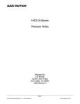
The Cycle Test window will dynamically adjust to whether the Controller is in
Torque, Velocity, or Position mode. Each text-input box has a tool-tip available for
instruction; just rest your mouse over the text box to see the help. A view of the
Cycle Test configured to run a Velocity cycle is shown below:
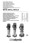
3.12 Auto Phase
The Auto Phase view can be used to automatically determine the phase
relationship (offset) between the motor resolver and the motor rotor. Warning,
running this test will spin the motor – typically a few revolutions in both directions.
The Auto Phase view assumes the Controller has been basically configured for
its Motor Parameters, Limits, and Loop Gains. Essentially the Controller should
be configured from the motor data sheet as best as possible.
Once the Controller is properly configured, open Auto Phase and review the
settings on the left side of the window. The motor will be driven in Manual
feedback (See the Manual Feedback section below).
ESI Motion Document 100266 Revision B
10/23/2015
Page 26
Controller User’s Manual
Manual Feedback requires a reasonably large current to force rotation – typically
20 to 30% of the maximum continuous current of the motor. The Auto Phase view
will automatically set the Iq Command to 20% of the value set by
Mx.MaxCurrentCommand.
The velocity set should be small compared to your application. 10RPM is a typical
number. The Acceleration (Accel RPM) should also be small compared to your
application, and 50 RPM is the default value.
Lastly set the check that the motor Pole Pairs value is the correct value for the
motor being tested. Click Start to run the test.
The motor should spin in both directions. If it does not, check the line
stating “Runtime info”, which displays the applied IqCmd, and the measured
VBus and RPM. For example, a VBus=0 would indicate a problem with the
motor power supply connection. If the Output window displays “Motor
faulted”, then a run-time fault occurred during this test.
4
MOTOR TUNING
The ESI Dragon Line of modular motion control employs an industry
standard current-loop, velocity-loop, and in some applications a positionloop. Each of these control loops utilizes proportional, integral, and
derivative (PID) error correction to achieve the desired performance.
This section describes the procedure for tuning each control loop to match
the intended application. After the tuning is completed, for applications
ESI Motion Document 100266 Revision B
10/23/2015
Page 27
Controller User’s Manual
including physical feedback (resolver or encoder) or for sensorless
operation, setting the initial motor phase angle is described.
4.1
Safety First
Prior to controlling the motor in any way, the motor limits should be programmed
into the ESI Controller.
1. Limit the user-current command (if in Torque mode) and the absolute
currents applied to the motor:
a. In the HiDS Limits tab, set the Positive Current Command to the
specified motor maximum continuous current rating.
b. If the negative current limit is not the same as the positive limit, in
the HiDS Limits tab, set the Negative Current Command to the
negative (-1 times) the specified motor maximum continuous
current rating.
c. In the HiDS Limits tab, set the Over Current Fault to 1.25 times
the specified motor maximum current; this allows for brief currentspikes during normal operation. Note this initial Over Current Fault
setting. Depending on the motor and the application, often this
setting can be much higher.
2. The ESI Controller can be set to disable the motor should the motor RPM
reach a maximum level.
a. In the HiDS Limit tab, set the Maximum Velocity to the specified
motor maximum speed.
For this procedure, initially limit the motor power-supply voltage to ½ of the
specified motor maximum voltage. Depending on your default Vbus limits,
you may have to adjust the Maximum Bus Voltage, the Minimum Bus
Voltage, and the Precharge Voltage (all on the LimitsA tab) to be scaled
down for the reduced power-supply setting.
4.2
Motor Parameters
There are some fundamental properties of the motor that the Controller needs to
be configured with to properly drive the motor. All of these parameters should be
available from the motor manufacturer’s data sheet.
1. Inductance: In the HiDS Motor tab, set the Line-to-Neutral Inductance to
½ of the measured or specified motor Line-to-Line inductance.
2. Resistance: In the HiDS Motor tab, set the Line-to-Neutral Resistance to
½ of the measured or specified motor Line-to-Line resistance.
ESI Motion Document 100266 Revision B
10/23/2015
Page 28
Controller User’s Manual
3. Back-EMF Constant Ke: In the HiDS Motor tab, set the Line-to-Neutral
Voltage Constant to the motor Ke. Note the ESI vector controller uses Ke
units of Volts-peak/RPM Line to Neutral. To convert to Line-to-Line, KeL-L
= KeL-N * √3.
4. Motor Pole Pairs: In the HiDS Motor tab, set the Motor Pole Pairs to the
specified motor pole pairs.
4.3
Current-Loop Tuning
4.3.1
Common Setup
These steps are common to each of the three methods below.
1. Login to the Controller using HiDS. For HiDS login and installation
information, refer to the HiDS User Manual.
2. Enable the manual response feedback, which disables the physical motor
velocity feedback (resolver, encoder, etc):
a. In HiDS Motor tab, select the Manual feedback method in the
Feedback drop-down list.
3. Enable the Controller Torque mode (by disabling velocity mode):
a. In HiDS Loop Gains tab, select Torque method in the Control
Mode drop-down list.
4. Disable the current-loop integral error correction, which allows an
unobstructed view of the proportional gain effect:
a. In HiDS Loop Gains tab, set the Current Loop Ki = 0.
5. Initialize the current-loop gain to a small value, to avoid possible
oscillations from the start:
a. In HiDS Loop Gains tab, set the Current Loop Kp = 1.
6. Set the user-RPM value to zero, which provides a DC-current output to the
motor during the step-response tests. In the HiDS Run Panel, set variable
RPMUserCommand to 0.
4.3.2
Step Response Procedure
1. Connect a current-probe to either the A (U) or B (V) phase input wires to
the motor, attach the current-probe to an oscilloscope, and configure the
oscilloscope to capture the current rising edge. Note the oscilloscope time
scale should be approximately 100us/div.
ESI Motion Document 100266 Revision B
10/23/2015
Page 29
Controller User’s Manual
a. Alternately, the HiDS Scope can be used, but the resolution is
limited to 25us per data point. Set channel 1 to IqUserCommand
(for trigger), and set channel 2 to Ma.Iq.
2. First test the setup: During this tuning procedure the motor should not
turn. In the HiDS Run Panel, set variable IqUserCommand to
approximately 10% of the motor’s rated constant-current value, and click
on the HiDS Run Panel [Run] button. You may hear some motor hum, but
the motor should not turn. Click on the HiDS Run Panel [Stop] button.
3. In the HiDS Run Panel, set variable IqUserCommand to 0, and click on
the HiDS Run Panel [Run] button. Then set variable IqUserCommand
value to approximately 10% of the motor’s rated constant-current value,
and observe the step response on the oscilloscope. For most applications,
the goal is to achieve the classic critically damped response.
4. On the HiDS Compensation page, adjust Current Loop Kp and re-run
the step response (while leaving the motor “running”, set variable
IqUserCommand to zero, and then set variable IqUserCommand to
10% of the motor’s rated constant-current value) until a critically damped
response is achieved.
4.3.2.1
Troubleshooting
1. If the motor inductance is relatively large, the motor power-supply
voltage may have to be increased to achieve the characteristic step
response.
2. If the initial response is an oscillation, the initial Current Loop Kp value
of 1 may still be too large. Reduce Current Loop Kp to 0.1 and retry.
4.3.3
The “Ear” Procedure
If no test equipment is available, or if the environment does not allow test
equipment to be easily used, the proportional gain can often be effectively
determined by adjusting the gain upward until the system starts to become
unstable (oscillates). Then the gain is set to ½ of that value.
Starting with a reasonably small Current Loop Kp value, in the HiDS Run
Panel, set variable IqUserCommand to 0, and click on the HiDS Run
Panel [Run] button.
Then set variable IqUserCommand to approximately 80% of the motor’s
rated constant-current value, and observe and listen to the motor system.
Increase variable Current Loop Kp until the motor system starts to
ESI Motion Document 100266 Revision B
10/23/2015
Page 30
Controller User’s Manual
visually or audibly oscillate. At that point, set the final Current Loop Kp
value to ½ of the value that started the oscillation.
4.3.4
Setting the Current-Loop Integral
Establishing precise integral values can be very application specific, but
generally the ESI Controller current-loop integral can be set as follows:
1. In the Loop Gains tab, set the Integral Time Constant to 6ms.
2. Click the [Compute Ki] button, which will automatically set Ma.Ki based
on the High Speed Loop Frequency.
4.4
Velocity-Loop Tuning
Tuning the velocity loop requires precise knowledge of the actual motor position.
This step cannot be performed unless the motor is properly phased. This section
applies to motors with physical feedbacks (resolver, encoder, etc). For
sensorless velocity-loop tuning, see below.
1. Set the appropriate physical motor velocity feedback (resolver, encoder,
etc):
a. In HiDS Motor tab, select the Resolver, Encoder, or Hall
feedback method in the Feedback drop-down list.
2. Enable the Controller Velocity mode:
a. In HiDS Loop Gains tab, select Velocity method in the Control
Mode drop-down list.
3. Disable the velocity-loop integral error correction, which allows an
unobstructed view of the proportional gain effect:
a. In HiDS Loop Gains tab, set the Velocity Loop Ki = 0.
4. Set the user-current value to zero, which may be non-zero from the
current-loop tuning.
a. In HiDS Run Panel, set the IqUserCommand = 0.
5. Disable velocity ramping (set to an overly large value), which would affect
the gain tuning:
a. In HiDS VelocityLoop page, set variable MaVL.AccelRPMPerSec
= 100000.
6. In the HiDS Run Panel, set the RPMUserCommand value to
approximately 10% of the motor’s rated speed value. Note this value must
ESI Motion Document 100266 Revision B
10/23/2015
Page 31
Controller User’s Manual
be large enough to allow the selected feedback mechanism to read above
its noise floor. Typically this minimum value is 100 RPM.
7. Attach the unfiltered velocity value (measured by the selected feedback)
to a HiDS digital test point.
a. In the HiDS Summary page, right click on the
MaVL.RPMUserCommand variable and select Send to Test Point
and select DTP1.
b. In the HiDS Resolver (or Hall or Encoder for encoder) page, right
click on the RadiansPerSecond variable and select Send to Test
Point and select DTP2.
c. Open the HiDS oscilloscope, and configure the oscilloscope to
trigger on the rising edge of the DTP1 signal.
8. In the HiDS Run Panel, set the RPMUserCommand value to 0, and click
on the [Run] button; then set RPMUserCommand value to approximately
10% of the motor’s rated speed value, and observe the step response on
the oscilloscope. For most applications, the goal is to achieve a classic
critically damped response.
9. On the HiDS Loop Gains tab, adjust the Velocity Loop Kp value and rerun the step response (while the motor is “running”, set the
RPMUserCommand value to 0, and then set the RPMUserCommand
value to approximately 10% of the motor’s rated constant-current value)
until a critically damped response is achieved.
4.4.1
Sensorless Velocity-Loop tuning
While the above procedure fundamentally applies to sensorless, there are
some key differences. When in velocity-mode, there are 2 independent
regions of sensorless control – open-loop and closed-loop. Sensorless
open-loop (below MxSmo.ClosedLoopRPMThreshold) is essentially the
same as manual feedback, so there is no closed-loop velocity-loop
control. Hence the Velocity Loop Kp and Ki values are irrelevant until the
closed-loop region is entered.
There are then 2 ways of tuning a sensorless velocity loop:
1. Once the motor has exceeded the MxSmo.ClosedLoopRPMThreshold
RPM, then a velocity step-response can be entered (for example if the
closed-loop RPM threshold was 1000RPM, a step from 1200 to 1300 RPM
could be used), and the physical-feedback method above can be used as
a guide to finish the tuning. This method is problematic though, because
the velocity-loop must already be tuned sufficiently in order to exceed the
closed-loop RPM threshold.
ESI Motion Document 100266 Revision B
10/23/2015
Page 32
Controller User’s Manual
2. Alternatively, set the Velocity Loop Ki = 0, and set the Velocity Loop Kp
= 0.0001, and try to run the motor into the closed-loop region. With such a
low Kp, you may see the motor spin up to the desired RPM and then
slowly spin down (because there is insufficient gain to compensate for the
RPM error). Start doubling the Velocity Kp until basic control is achieved.
You can then optimize the Velocity Kp by attempting to minimize the noise
on the measured Iq.
4.4.2
Setting the Velocity-Loop Integral
Establishing precise integral values can be very application specific, but
generally the ESI Controller velocity-loop integral can be set as follows:
While still observing the velocity step response on the oscilloscope, adjust
the Velocity Loop Ki until the velocity stabilizes in a time appropriate for
the application.
4.5
Saving Values
In the HiDS Settings menu, click on the Save Objects to EEPROM (nonvolatile) memory selection. This will save all of these parameters above
into non-volatile memory.
Alternately, the resultant gain values and motor phase offset values can be
saved into an importable text file, which can be imported as needed. Refer
to the parameter-import section for instructions.
Loading new firmware will change saved-EEPROM variables back to the
default settings, so it is recommended that an importable text file be created
to insure changes can be recovered.
4.6
Comparing Current Settings with a Text File
It is recommended that all configuration changes be saved to an importable
text file. This insures changes are not lost, because a firmware upgrade will
change saved-EEPROM variables back to default.
To compare the current Controller configuration with the settings in a text
file, in the HiDS Settings menu, click on the Compare Active Objects with
txt file selection. This will compare all of the parameters in the text file with
the current settings on the target. The changes will be shown on the
resulting dialog, and if there are too many changes to display, all changes
ESI Motion Document 100266 Revision B
10/23/2015
Page 33
Controller User’s Manual
will be saved to the log file in the Windows ProgramData directory, which is
Windows-OS-version specific. In Windows 7, this directory is in
C:\ProgramData. In this directory, there is a \ESI Motion\HiDS\{version}
directory (where version is the HiDS version).
5
MOTOR PHASING
Motor vector control requires precise knowledge of the actual rotor phase, so the
alignment (phase-offset) between the rotor and the physical feedback (resolver,
encoder, etc) must be established. Different motor manufacturers establish the
resolver/encoder to rotor aligment differently, so typically the phase angle must
be determined during the initial motor operation.
1. Set the appropriate physical motor velocity feedback (resolver, encoder,
etc.):
a. In HiDS Motor tab, select the Resolver or Encoder feedback
method in the Feedback drop-down list.
2. Enable the Controller Torque mode (by disabling velocity mode):
a. In HiDS Loop Gains tab, select Torque method in the Control
Mode drop-down list.
3. Initialize the motor phase to zero:
a. In HiDS MotorA (or B) tab, set the Resolver (or Encoder) Offset
to 0.
4. In the HiDS Run Panel, set the IqUserCommand value to approximately
5% of the motor’s rated constant-current value.
5. While still in the HiDS Run Panel, click on the [Run] button. If the motor
spins, go to step 6. If the motor does not spin, try:
a. In the HiDS Motor tab, Change the Feedback Direction from
Forward to Reverse (or visa-versa), and re-run.
b. Increase the IqUserCommand as high as 20% of the motor’s rated
constant-current value.
c. In HiDS MotorA (or B) tab, set the Resolver (or Encoder) Offset
to 90.
6. The objective is to change the Resolver (or Encoder) Offset until the
motor stops spinning, regardless of the amount of IqUserCommand
(torque) which is applied (which indicates the vector-control is 90° out of
phase). Adjust the Resolver (or Encoder) Offset value and re-run. Note
as you approach the zero-spin value, you may have to increase the
IqUserCommand slightly to allow an accurate phase value to be
determined.
ESI Motion Document 100266 Revision B
10/23/2015
Page 34
Controller User’s Manual
7. When the stopping phase is properly estimated, write it down. Next add
90° to the Resolver (or Encoder) Offset, return to the Run Panel, and
re-run
a. If the current and RPM sign are the same, then this phase (stopvalue plus 90°) is the correct phase to save.
b. If the current and RPM sign are not the same, then subtract 90°
from the stopping phase value found in step 6. Verify in the Run
Panel that the current and RPM sign are now the same. This
phase (stop minus 90°) is the correct phase to save .
6
THEORY OF OPERATION
This section describes theory of operations of the Dragon-Series Servo
Controller current-loop and velocity-loop. With the HiDS User Manual, it is the
objective that the reader, with adequate knowledge of motor operations, could
configure the motor and monitor its performance via HiDS.
6.1
6.1.1
The Current Loop
Clark and Park Transforms
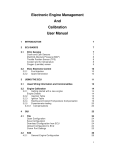
An in-depth description of vector-control of current is not described here; the
references above describe that control at varying depths. However a simplistic
view of the current loop is shown below.
ESI Motion Document 100266 Revision B
10/23/2015
Page 35
Controller User’s Manual
For simplicity, the current loop can be divided into sections below.
ESI Motion Document 100266 Revision B
10/23/2015
Page 36
Controller User’s Manual
6.2
Clark and Park Transforms
For each motor controlled, the currents Mx.Ia and Mx.Ib (alternately the U and V
phase) are measured. It is not necessary to measure Mx.Ic (W phase) as it is
assumed that Ia + Ib + Ic = 0. Through 2 mathematical transformations, called
the Clark transform and the Park transform, the time-varying measured currents
are transformed into a time-invariant reference frame that is rotating with the
electrical angle.
The output from the Clark transform is Mx.Ialpha and Mx.Ibeta, and in addition
the Park transform requires precise knowledge of the electrical angle between
the torque and flux vectors; this is accomplished via a mechanical measurement
of the angle between the rotor and stator via a physical feedback mechanism
such as encoder or resolver, or an estimation via a sensor-less algorithm.
To achieve the proper electrical angle, the motor parameters must be properly
configured with the Motor pole pairs. In addition if a motor phase is swapped, the
MotorX.FeedbackDirection can be changed (-1 or +1) to swap the sign of the
feedback.
ESI Motion Document 100266 Revision B
10/23/2015
Page 37
Controller User’s Manual
Finally, if the feedback mechanism is not aligned with the motor, the
MotorX.FeedbackPhase must be entered to offset the feedback angle from the
motor position. Refer to ESIMotion Motor Tuning and Phasing Procedure for
details on motor phase calibration.
The output from the Park transform is the torque vector Mx.Iq and the flux vector
Mx.Id, which are the measured/calculated vectors in the rotating frame to be
used in compensating for error from the desired Mx.IqCmd and Mx.IdCmd.
6.2.1
IQ Command Determination
In the rotating reference frame, the resulting currents, Mx.Iq and Mx.Id, are used
as feedback to compare against the input IQ command (Mx.IqCmd), which is the
torque component and the ID command (Mx.IdCmd), which is the flux
component. Generally Mx.IqCmd is the sole commanded current, and the
Mx.IdCmd is kept at zero to maximize torque.
The input current command into the current-loop, Mx.IqCmd, is the sum of 4
possible current commands: While running in Velocity mode, the Velocity-loop
output produces a Mx.DesiredCurrent input to the Current Loop. From the Utility
Test page, the always running SinTest.output is a sinusoidal value between 0
and 1, with a frequency set by SinTest.frequency. The test input amplitude to the
current loop can be set via the variable SinTest.iq_amplitude, which allows a
sinusoidal input at the specified frequency and amplitude for debug test.
Similarly, the IQCommnad input can come in via the analog input, which is
scaled by the variable Mx.IcmdInputScale. Finally if running in Torque mode, the
actual Mx.IqUserCommand is the current command that is input via the HiDS
Run Panel, the CAN interface, or via another serial interface.
Note there is no automatic zeroing of these input variables, so for example if
running in Velocity mode, you should insure the Mx.IqUserCommand is zero (or it
will be summed in).
ESI Motion Document 100266 Revision B
10/23/2015
Page 38
Controller User’s Manual
The final Mx.IqCmd output is then limited by the Configuration settings of
Mx.MinCurrentCommand and Mx.MaxCurrentCommand. Note these are
software limits of the current commands. Exceeding these limits simply restrains
the current command input to the control system – no error occurs if these limits
are exceeded. Mx.IqCmd is thus the desired IQ command to the control system,
prior to error compensation.
6.2.2
IQ and ID Error Compensation
The Mx.Iq output is the torque component of the calculated Park transform from
the measured Mx.Ia and Mx.Ib currents and the feedback (resolver, encoder,
sensor-less) angle. Thus Mx.IqError is the error between the desired IQ
command and the resultant IQ, and it is the goal to reduce this IQ error to zero.
First the Mx.IqError is reduced via a Proportional and Integral
compensation using the configurations of Mx.Kp (Gain), Mx.Ki (Integral),
and Mx.IntegralMin and Mx.IntegralMax (to limit the integral error buildup).
Note if Mx.AutoSetIntegralMinMax is set to 1 (true), the Mx.IntegralMin
and Mx.IntegralMax are automatically set to the maximum bus voltage.
ESI Motion Document 100266 Revision B
10/23/2015
Page 39
Controller User’s Manual
Secondly there can be feed-forward error compensation to help counter
the effects of motor-back-EMF-voltage (Mx.EMFFeedForward) and the
effects of IR increases (Mx.IRFeedForward). Of course these feed-forward
error compensations rely on reasonably accurate configurations of the
motor voltage constant MotorX.Ke and the motor phase resistance
MotorX.Ohms. Typically this feed-forward is enabled (1), but it can be
disabled by setting Mx.UqFeedForwardEnable = 0 (false).
The error-compensation of IQ results in an intermediate voltage of Mx.Uq.
Somewhat independent from the IQ error compensation, the ID error is reduced
in a similar way. The Mx.Id output is the flux component of the calculated Park
transform from the measured Mx.Ia and Mx.Ib currents and the feedback
(resolver, encoder, sensor-less) angle. To maximize torque, the ID command,
Mx.IdCmd, is typically set to zero. Thus Mx.IdError is the error between the
desired ID command (zero) and the resultant ID, and it is the goal to reduce this
ID error to zero.
First the Mx.IdError is reduced via a Proportional and Integral
compensation using the configurations of Mx.Kp (Gain), Mx.Ki (Integral),
and Mx.IntegralMin and Mx.IntegralMax (to limit the integral error buildup).
Secondly there is feed-forward error compensation to help counter the
effects of reactive losses (Mx.UdFeedForward) with increasing frequency.
Of course this feed-forward error compensation relies on reasonably
accurate
configurations
of
the
motor
phase
inductance
MotorX.Inductance. Typically this feed-forward is enabled (1), but it can be
disabled by setting Mx.UdFeedForwardEnable = 0 (false).
The error-compensation of ID results in an intermediate voltage of Mx.Ud.
Note the unit change during this error correction process. The inputs to the error
correction stage are currents, yet the outputs are in units of voltage. This is the
unit transition point, which prepares us for the final output of (phase) voltages.
ESI Motion Document 100266 Revision B
10/23/2015
Page 40
Controller User’s Manual
6.2.3
The Inverse Clark and Park
The error-compensated IQ and ID result in the intermediate voltages of Mx.Uq
and Mx.Ud, which are fed into the Inverse Park transform.
To limit the bounds of the error correction, the Inverse Park voltage outputs,
Uaplha’ and Ubeta’ (not readable via HiDS), are checked against a maximum
obtainable command voltage. The voltage limit is MaxCommandVoltage, which is
approximately equal to the VBus (Mx.VBus) input ÷ 2 (the actual divider depends
on the hardware configuration, but this is very close). The voltage checked is the
Uα and Uβ voltage vector scalar, Mx.VoltageMagnitude =
+
. The
resultant Mx.Ualpha and Mx.Ubeta outputs are the Uaplha’ and Ubeta’ Inverse
Park transform outputs multiplied by the ratio of MaxCommandVoltage ÷
Mx.VoltageMagnitude. This “saturated” condition is often a warning to an
improperly controlled motor or possibly an error-condition, and the condition is
flagged by Mx.Saturated = 1. The precursor to saturation is indicated by
Mx.PreSaturated = 1; the Controller can often tolerate pre-saturation for some
time, but the saturated condition is effectively an error state. The VBus utilization
can also be monitored via Mx.VBusUtilization, which should be between 0 and 1.
The saturation-limited Mx.Ualpha and Mx.Ubeta outputs from the Inverse Park
transform are inputs to the Inverse Clark transform, which produces the motor
phase voltages to apply, Mx.Va, Mx.Vb, and Mx.Vc; for a 3-level bridge
application, the voltages are represented by Mx.VaRaw, Mx.VbRaw, and
Mx.VcRaw.
The phase voltages are then applied to the motor via a pulse-width-modulated
Vbus (ADCResults.VBus).
For the complete diagram, refer to Appendix B.
ESI Motion Document 100266 Revision B
10/23/2015
Page 41
Controller User’s Manual
6.3
The Velocity Loop
The Velocity loop is effectively an independent control loop outside the Current
loop, which then inputs a current (Mx.DesiredCurrent) into the Current loop.
Once again for simplicity, the velocity loop can be divided into sections below.
6.3.1
RPM Command Determination
The preliminary MxVL.RPMCommand output is the summed result of the
Velocity-mode MxVL.RPMUserCommand (input via the CAN/Serial input or the
Run Panel), the MxVL.DesiredRPM result from the Position Loop (if available),
the Test input (SinTest.output * SinTest.VelocityCommandAmp), and the analog
input (MxVL.VcmdInputScale * IcmdAnalogInput).
The final MxVL.AccelLimitedRPMCommand output is then limited by the user
Configuration setting of MxVL.AccelRPMPerSec. Note this is a software limit of
the rate of change of the velocity command (acceleration / deceleration).
Exceeding this limit simply restrains the velocity command input to the control
system
–
no
error
occurs
if
this
limit
is
exceeded.
MxVL.AccelLimitedRPMCommand is thus the desired RPM command to the
control system, prior to error compensation.
ESI Motion Document 100266 Revision B
10/23/2015
Page 42
Controller User’s Manual
6.3.2
RPM Error Compensation
MxVL.RPMError is the error between the desired RPM command and the
measured velocity via the available feedback (resolver, encoder, or sensor-less),
and it is the goal to reduce this RPM error to zero.
First the MxVL.RPMError is reduced via a Proportional and Integral
compensation using the configurations of MxVL.VelocityKp (Gain),
MxVL.VelocityKi (Integral), and MxVL.VelocityIntegralMin and
MxVL.VelocityIntegralMax (to limit the integral error buildup). Note if
Mx.VelocityAutoSetIntegralMinMax is set to 1 (true), the
Mx.VelocityIntegralMin and Mx.VelocityIntegralMax are automatically set
to the maximum current limit.
Secondly there are feed-forward error compensation to help counter the
effects of friction (MxVL.FrictionFeedForward), and the effects of inertia
(MxVL.StepFeedForward). Typically these feed-forwards are disabled (0),
but they can be enabled by setting these values to non-zero.
Note the unit change during this error correction process. The inputs to the error
correction stage are velocities, yet the outputs are in units of current. This is the
unit transition point, which prepares us for the final output of (command) current.
Finally if MxVL.VelocityEnable = 0 (false), which is torque mode, the
Mx.DesiredCurrent value is discarded. If MxVL.VelocityEnable = 1 (true), which is
velocity mode, the Mx.DesiredCurrent value is summed into the Current loop
input described above.
For the complete diagram, refer to Appendix C..
ESI Motion Document 100266 Revision B
10/23/2015
Page 43
Controller User’s Manual
6.4
Manual Feedback
Manual Feedback is a test mode that allows simple, often unloaded, motor
operation. Manual Feedback is useful to troubleshoot physical feedback
(encoder, resolver, hall, etc.) problems, or other basic motor-control problems.
When Manual Feedback is selected, the “measured” feedback angle is
automatically calculated based on the RampRpmPerSecond (acceleration) value.
Manual Feedback is often used unloaded (without significant mass connected to
the motor) because, in this mode, there is no physical feedback to determine the
necessary phase-voltage changes to maintain motor control.
Manual Feedback essentially provides an AC voltage to the motor phases with
the frequency determined by ManualFeedbackConfigA.RPM. To use Manual
Feedback, the following procedure can be used:
1. In the HiDS MotorA tab, select the Manual feedback method in the
Feedback dropdown list.
2. In HiDS Loop Gains tab, select Torque method in the Control Mode
drop-down list.
3. In HiDS Advanced tab, ManualFeedback page, set variables
ManualFeedback
ConfigA.RPM
and
ManualFeedbackConfigA.RampEnable both to 0.
4. In HiDS Advanced tab, ManualFeedback page, set variable
ManualFeedback ConfigA.RampRpmStop to the desired final RPM.
This RPM must be “easy” to achieve for the motor, and is often less
than 20% of the rated motor speed.
5. In HiDS Advanced tab, ManualFeedback page set variable
ManualFeedback ConfigA.RampRpmPerSecond to the desired
acceleration. This acceleration must also be “easy” to achieve for the
motor. A typical value is 500 RPM per second.
6. In the HiDS Run Panel, set the IqUserCommand to 25% of the rated
motor current. This value must be large enough to force commutation
of the motor, essentially without feedback.
7. In the HiDS Run Panel, click [Run]. Note there may be some small
movement in the motor as the DC-current may align the rotor to stator
magnets.
8. In HiDS Advanced tab, ManualFeedback page set variable
ManualFeedback ConfigA.RampEnable to 1. The motor should begin
to spin from 0 to Manual FeedbackConfigA.RampRpmStop using an
acceleration of ManualFeedback ConfigA.RampRpmPerSecond. If the
ESI Motion Document 100266 Revision B
10/23/2015
Page 44
Controller User’s Manual
motor fails to spin, click [Stop] on the Run Panel and try increasing the
IqUserCommand to as much as 50% of the rated motor current.
ESI Motion Document 100266 Revision B
10/23/2015
Page 45
Controller User’s Manual
7
APPENDIX A: HIDS VARIABLE GLOSSARY
The data-types and bounds shown below should be considered when setting and
reading a HiDS variable; however all Controller variables are exchanged with
HiDS as single-precision floating-point numbers, so care should be given to
insure variables are configured within their defined bounds or only using the
acceptable values.
All MotorA variables descriptions below apply to Motor B and Motor C
variables for multiple-axis configurations.
7.1
Summary
Description:
7.2
All variables shown on this page are copies of variables from other pages.
This page only congregates commonly viewed variables. The descriptions
of each of these are shown below.
Analog
Variable name: Various
Summary:
The raw measured values for various currents, voltages, and
temperatures in the system. Note there may be more variables shown
on this page than are actually measured within the particular controller.
HiDS location: Shown on Analog page in Advanced tab.
Description:
Read Only. This page is unlikely to be viewed during normal operation,
but it might be useful when trying to determine if a Controller is missing
an external connection, or if a Controller may have an internal failure.
The various internal fixed voltages are shown (+5V, 3.3V, 1.9V, 24V,
etc.), and the raw measured values for all other analog readings.
Individual Descriptions:
Vbus:
Motor Power measurement in Volts. On Dragon1-based Controllers, this
measurement may only be available while the controller is enabled.
D24VMon, D5VAMon, D3_3VAMon, D2_5VAMon, and D2_5VARef:
These are internal DC voltages, in Volts, that are expected to be close to the numeric
named values.
ADCResults.MaVa, MaVb, and MaVc:
These are the motor phase A, B, and C (U, V, and W respectively)
voltages in Volts.
ADCResults.MaIa, MaIb, and MaIc:
ESI Motion Document 100266 Revision B
10/23/2015
Page 46
Controller User’s Manual
These are the intermediate motor phase A, B, and C (U, V, and W
respectively) currents in Amps, pre-calibration. See Mx.Ia, Mx.Ib, and
Mx.Ic on the MotorXHSL page for the calibrated values.
Mx.Ibus:
Motor power current measured in Amps.
Mx. IcmdAnalogInput: Voltage measured, in Volts, of the analog command input. In a
control mode, the signal may be used to give the Controller a torque or
velocity command. In test mode, the signal may be used to inject a test
signal into the system.
Mx.BrakeI:
The measured current, in Amps, of the current supplied to the motor
brake.
DSPTemp:
The measured temperature, in degrees C, of the internal Digital Signal
Processor.
MaxCommandVoltage:
This is the dynamically calculated maximum voltage, in Volts, that is
available to commutate the motor. Once Mx.VoltageMagnitude exceeds
the MaxCommandVoltage, the current-loop is referred to as saturated
and is no longer able to produce the desired current, velocity, or
position.
7.3
BIT (Built In Test)
The BIT variables are shown in groups as follows:
<measurement name> BIT.enable indicates whether the BIT is enabled(1) or
disabled(0).
<measurement name> BIT.limit indicates the failure threshold, which is set to the units of
the measurement being tested; read/write.
<measurement name> BIT.current_count indicates the number of failed tests; note this
count is cumulative, not consecutive; read only.
<measurement name> BIT.max_count indicates the maximum number of failed tests.
This variable is not used for a pass or fail determination, but can be
used to indicate the BIT may be close to failure; read only.
<measurement name> BIT.trip_count indicatesthe number of failed counts to show fault;
note this count is cumulative, not consecutive. Unless otherwise
indicated, each test occurs every 1 millisecond; read only.
<measurement name> BIT.WarningEnable indicates whether the BIT warning check is
enabled(1) or disabled(0). Warnings have no effect on run-time, and are
typically reported via CAN or RS422 to the upper-layer control system.
<measurement name> BIT.WarningLimit indicates the warning threshold, which is set to
the units of the measurement being tested; read/write.
<measurement name> BIT.WarningCount indicates the number of warning-exceeded
tests; note this count is cumulative, not consecutive; read only.
The measurement limits can be configured in the [Limits] tab, or they can be changed by
ESI Motion Document 100266 Revision B
10/23/2015
Page 47
Controller User’s Manual
adjusting the <measurement name> BIT.limit variable located on the
BIT page in the Advanced Tab:
Variable name: VbusOvervoltageBIT and VbusUndervoltageBIT
Description:
Read / Write. Measures in Volts the motor bus voltage /motor power
supply voltage for an over/under voltage condition.
Tab name:
On the [Limits] configuration tab, these variables are referred to as the
Min Bus Voltage and Max Bus Voltage.
Units/Bounds: Volts. The over-voltage limit is set to the maximum allowable voltage of
the motor, or the Controller, whichever is lower. The under-voltage is
typically set lower than any operating voltage possible, and is typically
used to disable the Controller should motor-voltage be disconnected or
lost.
Variable name: MaIGBTTemperatureBIT
Description:
Read / Write. Each IGBT (insulated-gate bipolar transistor) has an
individual thermistor for temperature monitoring, and this variable tests
the maximum values of all IGBT thermistors, in degrees C.
Tab name:
On the [Limits] configuration tab, these variables are referred to as the
IGBT Temperature.
See also:
MbIGBTTemperatureBIT is the Motor B equivalent.
Units/Bounds: Degrees C. The limits depend on the Controller electronic configuration.
Variable name: MaMotorTempBit
Description:
Read / Write. If the motor has an available thermistor for temperature
monitoring, this variable can be used to report a warning or failure fault,
and is reported in degrees C.
Tab name:
On the [Limits] configuration tab, this variable is referred to as the Motor
Temperature Limit.
See also:
MbMotorTempBit is the Motor B equivalent.
Units/Bounds: Degrees C. Set to the maximum temperature of the motor.
Variable name: DSPTemperatureBIT
Description:
Read / Write. The internal DSP (Digital Signal Processor) has an
internal thermistor for temperature monitoring, in degrees C.
Tab name:
On the [Limits] configuration tab, this variable is referred to as the DSP
Temperature Limit.
Units/Bounds: Degrees C. Typically set to 90⁰
Variable name: MaOverspeedPos
Description:
Read / Write. Each motor has a maximum safe operating speed, and
this variable will disable the motor if the RPM-threshold is exceeded.
Tab name:
On the [Limits] configuration tab, this variable is referred to as the
Positive Velocity Limit.
Units/Bounds: RPM. Set to the maximum speed of the motor.
Variable name: MaLossOfFeedback
Description:
Read / Write. For resolver feedbacks, this test measures the average
RMS voltage of the Resolver Sine and Cosine inputs, and will disable
the motor should a feedback be disconnected. For a Serial Encoder,
ESI Motion Document 100266 Revision B
10/23/2015
Page 48
Controller User’s Manual
Tab name:
Units/Bounds:
this BIT is overloaded to check for SerialEncoderData.Error to equal
True (1) or False (0).
On the [Limits] configuration tab, this variable is referred to as the Motor
Feedback Limit.
Volts-RMS. For Dragon1-resolver, this is typically 2V. For Dragon2resolver, this is typically 0.5V. For Serial-Encoders, this is typically 0.5
(just between 1 and 0).
Variable name: I2T
Description:
Read / Write. I2T (read I-squared-T) is an estimation of the energy
content in current transient conditions. Because a motor can often
handle short current transients in excess of rated currents, this test can
help protect against motor overheating or damage due to excess
current transients.
Tab name:
On the [Limits] configuration tab, this variable is referred to as the I2T
Limit.
Units/Bounds: Amps2 * Degrees-C; unbounded.
For each fault test above, there are warning checks that can be independently enabled
or disabled. The equivalent warning variable names are prefaced with
“Warning”.
7.4
Cal
Variable name: Various
Summary:
The current-calibration values, as well as any other customer or
application specific calibrations.
HiDS location: Shown on Cal page in Advanced tab.
Description:
Read Only. Besides ESI-internal debug variables, this page is only
contains customer-relevant variables should there be customer or
application specific calibrations. Please refer to the customer-specific
HiDS addendum for these variables.
7.5
CAN
Variable name:
Summary:
HiDS location:
Description:
CanAddresses.ChannelNumber
The default channel number of the CAN HiDS interface.
Shown on CAN page in Advanced tab.
Read / Write. For Controllers using CAN communication for HiDS, this
is the channel number shown on the initial connection view when HiDS
first starts. For an application that has 2 or more Controllers connected
to the same PC, this channel number can be assigned uniquely to each
Controller, which allows the PC to address each Controller differently.
To change this value, one should insure the USB interface works first,
because making a mistake here may require USB connectivity to
correct. To take effect, change the channel number (to 1 for instance),
ESI Motion Document 100266 Revision B
10/23/2015
Page 49
Controller User’s Manual
Units/Bounds:
Variable name:
Summary:
HiDS location:
Description:
Units/Bounds:
Variable name:
Summary:
HiDS location:
Description:
Units/Bounds:
Variable name:
Summary:
HiDS location:
Description:
Units/Bounds:
select Settings->Save Objects to EEPROM, and reset the Controller.
Integer, the valid values are 0 to 15.
CanAddresses.BitRate
The default bit-rate of the CAN communication bus.
Shown on CAN page in Advanced tab.
Read / Write. For Controllers using CAN communication for HiDS or
control, the Controller will ship with a default bit-rate (often 1Mbps).
Should another value be desired, this variable can be changed to 500,
250, or 100 (Kbps). Note should an incorrect value be entered and
saved here, the only way to recover would be to login via USB and fix
the value.
Baud /bits per second, the valid values are 100000, 250000, 500000,
and 1000000.
CanAddresses.IncommingHids / OutgoingHids
The default addresses of the CAN HiDS interface.
Shown on CAN page in Advanced tab.
Read Only. For Controllers using CAN communication for HiDS, these
are the CAN addresses of the HiDS connection. All ESI Motion
Controllers ship using 1536 (0x600) for incoming and 1552 (0x610) for
outgoing. The actual addresses used are (1536 +
CanAddresses.ChannelNumber) for incoming and (1552 +
CanAddresses.ChannelNumber) for outgoing. If another CAN device is
one a shared bus, and if an address conflict occurs, then
CanAddresses.ChannelNumber can be changed to offset the HiDS
addresses.
Integer, the valid values are 1536 (0x600) to 1551 (0x60F) for incoming
messages and 1552 (0x610) to 1567 (0x61F) for outgoing messages.
CanNetworkUsedForHids
Indicates which CAN-bus HiDS is currently connected to.
Shown on CAN page in Advanced tab.
Read Only. For Controllers that support multiple CAN busses, the
variable indicates which CAN bus is in use for HiDS.
Integer, 1 indicates CAN-A, 2 indicates CAN-B, or 3 for CAN-C, if
available.
Variable name: CanControlInterfaceEnabled
Summary:
Enables (1) or disables (0) the external, non-HiDS, CAN command
interface.
HiDS location: Shown on CAN page in Advanced tab.
Description:
Read / Write. For Controllers using CAN communication for control, this
variable can enable or disable that control interface. Note in order to
use HiDS for motor control, it is likely that the external CAN control
interface must be disabled.
Units/Bounds: Boolean, the valid values are 0 or 1.
Variable name: CANCommandMsgID
Summary:
The message ID of the CAN command packet.
ESI Motion Document 100266 Revision B
10/23/2015
Page 50
Controller User’s Manual
HiDS location:
Description:
Units/Bounds:
Variable name:
Summary:
HiDS location:
Description:
Units/Bounds:
Variable name:
Summary:
HiDS location:
Description:
Units/Bounds:
Variable name:
Summary:
HiDS location:
Description:
Units/Bounds:
7.6
Shown on CAN page in Advanced tab.
Read / Write. For Controllers using CAN communication for control, this
variable sets the address / message ID of the incoming CAN command
packet.
Integer, the valid values are 1 to 2047 (11 bits).
CANFeedbackMsgEnable
A Boolean; enables (1) the CAN status message or disables (0) it.
Shown on CAN page in Advanced tab.
Read / Write. For Controllers using CAN communication for status, this
variable enables or disables that message. Setting this variable to 0
disables the message and 1 enables it.
Boolean, the valid values are 0 or 1.
CANFeedbackMsgID
The message ID of the CAN feedback/status packet.
Shown on CAN page in Advanced tab.
Read / Write. For Controllers using CAN communication for status, this
variable sets the address / message ID of the outgoing CAN feedback /
command packet.
Integer, the valid values are 1 to 2047 (11 bits).
CANFeedbackMsgInterval
The message ID of the CAN feedback/status packet.
Shown on CAN page in Advanced tab.
Read / Write. For Controllers using CAN communication for status, this
variable sets the interval in milliseconds between CAN status packet
transmissions.
Milliseconds, the valid values are 1 to 65535.
Compensation
7.6.1 Current Loop
Variable name: Mx.Kp
Summary:
Motor X current-loop gain compensation.
HiDS location: Shown on Loop Gains tab in Current Loop frame.
Description:
Read / Write. Used to adjust the Proportional Gain component for
reducing the error between the Iq command (Mx.IqCmd) and Iq actual
(Mx.Iq), and in addition reducing the error between the Id command
(Mx.IdCmd), which is typically zero and Id actual (Mx.Id).
See also:
Mb.Kp is the Motor B equivalent.
Units/Bounds: Volts per Amp, positive values only.
Variable name:
Summary:
HiDS location:
Description:
Mx.Ki
Motor X current-loop integral compensation.
Shown on Loop Gains tab in Current Loop frame.
Read / Write. Used to adjust the Integral Gain component for reducing
the error between the Iq command (Mx.IqCmd) and Iq actual (Mx.Iq),
ESI Motion Document 100266 Revision B
10/23/2015
Page 51
Controller User’s Manual
See also:
Units/Bounds:
and in addition reducing the error between the Id command
(Mx.IdCmd), which is typically zero and Id actual (Mx.Id).
Mb.Ki is the Motor B equivalent.
Unit-less, positive values only.
Variable name:
Summary:
HiDS location:
Description:
See also:
Units/Bounds:
Mx.IqErrorIntegral, Mx.IdErrorIntegral
Motor X current-loop IQ and ID current integral values.
Shown on Compensation page in Advanced tab.
Read Only. Displays the integral value of the loop.
Mb.IqErrorIntegral and Mb.IdErrorIntegral are the Motor B equivalents.
Volts, bounded by Mx.IntegralMin and Mx.IntegralMax.
Variable name: Mx.IntegralMin / Mx.IntegralMax
Summary:
Motor X current-loop integral compensation minimum and maximum
limits.
HiDS location: Shown on Loop Gains tab in Current Loop frame.
Description:
Read / Write. Integral Gain compensation is a slower moving
compensation, and under certain conditions is subject to error buildup.
These settings limit the integral value to the limits specified.
Note these are automatically set to the maximum output limits of the
loop if variable Mx.AutoSetIntegralMinMax is set to true (1).
See also:
Mb.IntegralMin and Mb.IntegralMax are the Motor B equivalents.
Units/Bounds: Volts, Mx.IntegralMax should be positive; Mx.IntegralMin should be
negative. The bounds are application specific, but should be less than
the motor-bus voltage available.
Variable name: Mx.AutoSetIntegralMinMax
Summary:
Auto-sets Motor X current-loop integral compensation minimum and
maximum limits.
HiDS location: Shown on Compensation page in Advanced tab.
Description:
Read / Write. If 1 (true), automatically sets the Mx.IntegralMax to the
voltage set by the VbusOvervoltageBIT.limit variable, and sets the
Mx.IntegralMin to the negative of the VbusOvervoltageBIT.limit variable.
See also:
Mb.AutoSetIntegralMinMax and Mb.AutoSetIntegralMinMax are the
Motor B equivalents.
Units/Bounds: Boolean, the valid values are 0 or 1.
Variable name: Mx.IdAutoSetToIqGainValues
Summary:
Auto-sets Motor X ID current-loop compensation variables to the IQ
compensation settings.
HiDS location: Shown on Compensation page in Advanced tab.
Description:
Read / Write. If 1 (true), automatically sets the Mx.IdKp and Mx.IdKi to
the Mx.Kp and Mx.Ki settings, which is the most common.
See also:
Mb. IdAutoSetToIqGainValues is the Motor B equivalent.
Units/Bounds: Boolean, the valid values are 0 or 1.
7.6.2 Velocity Loop
Variable name: Mx.VelocityKp
ESI Motion Document 100266 Revision B
10/23/2015
Page 52
Controller User’s Manual
Summary:
HiDS location:
Description:
Units/Bounds:
Variable name:
Summary:
HiDS location:
Description:
Units/Bounds:
Variable name:
Summary:
HiDS location:
Description:
Motor X velocity-loop gain compensation.
Shown on Loop Gains tab in Velocity Loop frame.
Read / Write. Used to adjust the Proportional Gain component for
reducing the error between the acceleration-limited Velocity command
(MxVL.AccelLimitedRPMCommand) and actual measured velocity
(either ResolverARpm or EncoderA.Rpm depending on the actual
feedback).
Amps per RPM, positive values only.
Mx.VelocityKi
Motor X velocity-loop integral compensation.
Shown on Loop Gains tab in Velocity Loop frame.
Read / Write. Used to adjust the Integral Gain component for reducing
the error between the acceleration-limited Velocity command
(MxVL.AccelLimitedRPMCommand) and actual measured velocity
(either ResolverARpm or EncoderA.Rpm depending on the actual
feedback).
Unit-less, positive values only.
Units/Bounds:
Mx.VelocityKd
Motor X velocity-loop derivative compensation.
Shown on Loop Gains tab in Velocity Loop frame.
Read / Write. Used to adjust the Derivative Gain component for
reducing the error between the acceleration-limited Velocity command
(MxVL.AccelLimitedRPMCommand) and actual measured velocity
(either ResolverARpm or EncoderA.Rpm depending on the actual
feedback). Note the derivative term is typically zero as derivative
compensation can often lead to loop instability.
Amps, positive values only.
Variable name:
Summary:
HiDS location:
Description:
Units/Bounds:
Mx.VelocityErrorIntegral
Motor X velocity-loop current integral value.
Shown on Compensation page in Advanced tab.
Read Only. Displays the integral value of the loop.
Amps, bounded by Mx.VelocityIntegralMin and Mx.VelocityIntegralMax.
Variable name: Mx.VelocityIntegralMin / Mx.VelocityIntegralMax
Summary:
Motor X velocity-loop integral compensation minimum and maximum
limits.
HiDS location: Shown on Loop Gains tab in Velocity Loop frame.
Description:
Read / Write. Integral Gain compensation is a slower moving
compensation, and under certain conditions is subject to error buildup.
These settings limit the integral value to the limits specified.
Note these are automatically set to the maximum output limits of the
loop if variable Mx.VelocityAutoSetIntegralMinMax is set to true (1).
Units/Bounds: Amps, Mx.VelocityIntegralMax should be positive;
Mx.VelocityIntegralMin should be negative. The bounds are application
specific, but should be less than the over-current value
(Mx.HardwareOvercurrent).
ESI Motion Document 100266 Revision B
10/23/2015
Page 53
Controller User’s Manual
Variable name: Mx.VelocityAutoSetIntegralMinMax
Summary:
Auto-sets Motor X velocity-loop integral compensation minimum and
maximum limits.
HiDS location: Shown on Compensation page in Advanced tab.
Description:
Read / Write. If 1 (true), automatically sets the Mx.VelocityIntegralMax
to the amperage set by the Mx.HardwareOvercurrent variable, and sets
the Mx.VelocityIntegralMin to the negative of the
Mx.HardwareOvercurrent variable.
Units/Bounds: Boolean, the valid values are 0 or 1.
7.6.3 Position Loop
Variable name: Mx.PositionKp
Summary:
Motor X Position-loop gain compensation.
HiDS location: Shown on Loop Gains tab in Position Loop frame.
Description:
Read / Write. Used to adjust the Proportional Gain component for
reducing the error between the acceleration-limited Position command
(MxPL. AccelLimitedRadiansCommand) and actual measured Position
(MotorXAbsolutePosition).
Units/Bounds: RPM per Radian, positive values only.
Variable name:
Summary:
HiDS location:
Description:
Units/Bounds:
Variable name:
Summary:
HiDS location:
Description:
Mx.PositionKi
Motor X Position-loop integral compensation.
Shown on Loop Gains tab in Position Loop frame.
Read / Write. Used to adjust the Integral Gain component for reducing
the error between the acceleration-limited Position command
(MxPL.AccelLimitedRadiansCommand) and actual measured Position
(MotorXAbsolutePosition).
Unit-less, positive values only.
Units/Bounds:
Mx.PositionKd
Motor X Position-loop derivative compensation.
Shown on Loop Gains tab in Position Loop frame.
Read / Write. Used to adjust the Derivative Gain component for
reducing the error between the acceleration-limited Position command
(MxPL.AccelLimitedRadiansCommand) and actual measured Position
(MotorXAbsolutePosition). Note the derivative term is typically zero as
derivative compensation can often lead to loop instability.
RPM, positive values only.
Variable name:
Summary:
HiDS location:
Description:
Units/Bounds:
Mx. RadiansErrorIntegral
Motor X Position-loop current integral value.
Shown on Compensation page in Advanced tab.
Read Only. Displays the integral value of the loop.
Amps, bounded by Mx.PositionIntegralMin and Mx.PositionIntegralMax.
Variable name: Mx.PositionIntegralMin / Mx.PositionIntegralMax
Summary:
Motor X Position-loop integral compensation minimum and maximum
limits.
HiDS location: Shown on Loop Gains tab in Position Loop frame.
ESI Motion Document 100266 Revision B
10/23/2015
Page 54
Controller User’s Manual
Description:
Units/Bounds:
Read / Write. Integral Gain compensation is a slower moving
compensation, and under certain conditions is subject to error buildup.
These settings limit the integral value to the limits specified.
Note these are automatically set to the maximum output limits of the
loop if variable Mx.PositionAutoSetIntegralMinMax is set to true (1).
RPM, Mx.PositionIntegralMax should be positive;
Mx.PositionIntegralMin should be negative. The bounds are application
specific, but should be less than the over-speed value
(MaOverspeedPos.limit).
Variable name: Mx.PositionAutoSetIntegralMinMax
Summary:
Auto-sets Motor X position-loop integral compensation minimum and
maximum limits.
HiDS location: Shown on Compensation page in Advanced tab.
Description:
Read / Write. If 1 (true), automatically sets the Mx.PositionIntegralMax
to the RPM set by the MaOverspeedPos.limit variable, and sets the
MaOverspeedPos.limit to the negative of the Mx.HardwareOvercurrent
variable.
Units/Bounds: Boolean, the valid values are 0 or 1.
7.6.4 Sensorless Velocity Loop
Variable name: MxSmo.VelocityKp, MxSmo.VelocityKi
Summary:
Velocity-loop proportional and integral compensations for sensorless
operation.
HiDS location: shown only in the Advanced Compensation page
Description:
Read / Write. These variables are analogous to their Mx.VelocityKp and
Mx.VelocityKi counterparts, but because of the increased latencies
associated with a sensorless feedback, these gains are often lower than
their physical feedback counterparts. These 2 values are used from 0
RPM until MaSmo.ClosedLoopRPMThreshold RPM is reached.
Units/Bounds: Kp is Amps per RPM; Ki is unit-less, positive values only.
Variable name: MxSmo.VelocityErrorIntegral
Summary:
Motor X Velocity-loop current integral value for the sensorless velocity
loop.
HiDS location: Shown on Compensation page in Advanced tab.
Description:
Read Only. Displays the integral value of the loop.
Units/Bounds: Amps, bounded by MxSmo.VelocityIntegralMin and
MxSmo.VelocityIntegralMax.
Variable name: MxSmo.VelocityIntegralMin / MxSmo.VelocityIntegralMax
Summary:
Motor X velocity-loop integral compensation minimum and maximum
limits for the sensorless velocity loop.
HiDS location: Shown on Loop Gains tab in Velocity Loop frame.
Description:
Read / Write. Integral Gain compensation is a slower moving
compensation, and under certain conditions is subject to error buildup.
These settings limit the integral value to the limits specified.
Units/Bounds: Amps, MxSmo.VelocityIntegralMax should be positive;
ESI Motion Document 100266 Revision B
10/23/2015
Page 55
Controller User’s Manual
MxSmo.VelocityIntegralMin should be negative. The bounds are
application specific, but should be less than the over-current value
(Mx.HardwareOvercurrent).
7.7
Config
Variable name:
Summary:
HiDS location:
Description:
Units/Bounds:
7.8
Control
Variable name:
Summary:
HiDS location:
Description:
7.9
RevertSettingsToFactoryDefault
Reverts all EEPROM values to the factory defaults.
Shown on Config page in Advanced tab.
Read / Write. Will reset the Controller and will reset all stored
parameters to the original factory default. It is highly recommended that
all Controller settings be exported prior to executing this, as there all
customer-changes will be lost.
Boolean, the valid values are 0 or 1.
Various
Motor A and Motor B state machine variables and brake controls.
Shown on Control page in Advanced tab.
Read Only. Typically only ESI-internal debug variables
Digital IO
Variable name: Various
Summary:
Shows the logic levels of the digital inputs and allows HiDS control of
the digital outputs.
HiDS location: Shown on Digital IO page in Advanced tab.
Description:
Read Only for Digital Inputs; Read / Write for Digital Outputs. Besides
ESI-internal debug variables, this page is only contains customerrelevant variables should there be customer or application specific
calibrations. Please refer to the customer-specific HiDS addendum for
these variables.
7.10 Encoder
Variable name:
Summary:
HiDS location:
Description:
Units/Bounds:
EncoderX.Degrees
Motor X Encoder position in degrees.
Shown on Encoder page in Advanced tab.
Read Only. Shows the motor position in degrees, normalized to 0 to
360⁰.
Degrees, the valid values are 0 to 360.
Variable name: EncoderX.Radians
ESI Motion Document 100266 Revision B
10/23/2015
Page 56
Controller User’s Manual
Summary:
HiDS location:
Description:
Units/Bounds:
Motor X Encoder position in Radians.
Shown on Encoder page in Advanced tab.
Read Only. Shows the motor position in radians, normalized to 0 to 2π.
Radians, the valid values are 0 to 2π.
Variable name:
Summary:
HiDS location:
Description:
EncoderX.RPM
Motor X velocity in RPM
Shown on Encoder page in Advanced tab.
Read Only. Shows the unfiltered motor velocity in revolutions per
minute.
RPM, unbounded.
Units/Bounds:
Variable name:
Summary:
HiDS location:
Description:
Units/Bounds:
EncoderX.FilteredRPM
Motor X velocity in RPM
Shown on Encoder page in Advanced tab.
Read Only. Shows the filtered motor velocity in revolutions per minute;
the filter is a ~4Hz low-pass filter, and this is the value shown on the
Run Panel RPM gauge (if encoder feedback is selected).
RPM, unbounded.
Variable name:
Summary:
HiDS location:
Description:
Units/Bounds:
EncoderX.RadiansPerSecond
Motor X velocity in Radians per second
Shown on Encoder page in Advanced tab.
Read Only. Shows the unfiltered motor velocity in radians per second.
Radians per second, unbounded.
Variable name:
Summary:
HiDS location:
Description:
EncoderX.RadiansSummed
Motor X Encoder accumulated position in Radians.
Shown on Encoder page in Advanced tab.
Read Only. Unless explicitly cleared, this variable shows the total
accumulated motor position in radians, since power on.
Radians, unbounded.
Units/Bounds:
Variable name: EnableEncoderPower
Summary:
A Boolean; enables (1) the +5V switchable output to the Interface
connector; 0 (False) disables it.
HiDS location: Shown on Encoder page in Advanced tab.
Description:
Read / Write. For Controllers supporting a +5V switchable output, this
variable allows HiDS control of that switch.
Units/Bounds: Boolean, the valid values are 0 or 1.
7.11 Fan
Note not all controllers support the Fan feature. The Fan state is updated
every 1 second.
Variable name: Fan.Hysteresis
Summary:
Sets the temperature hysteresis to turn the fan off.
HiDS location: Shown on Fan page in Advanced tab.
ESI Motion Document 100266 Revision B
10/23/2015
Page 57
Controller User’s Manual
Description:
Units/Bounds:
Variable name:
Summary:
HiDS location:
Description:
Units/Bounds:
Variable name:
Summary:
HiDS location:
Description:
Units/Bounds:
Read / Write The Fan is turned off when the filtered MaIGBTTemp is
less than (Fan.OnDegreesC - Fan.Hysteresis).
Degrees C, unbounded.
Fan.OnDegreesC
Sets the temperature threshold to turn on or turn off the fan.
Shown on Fan page in Advanced tab.
Read / Write The Fan is turned on when the filtered MaIGBTTemp is
greater than Fan.OnDegreesC. The fan is turned off when the filtered
MaIGBTTemp is less than (Fan.OnDegreesC - Fan.Hysteresis).
Degrees C, unbounded.
Fan.State
Indicates the on/off state of the fan.
Shown on Fan page in Advanced tab.
Read Only. False (0) indicates the fan is off. 1 (True) indicates the fan is
on.
Boolean, the valid values are 0 or 1.
Variable name: Fan.FaultState
Summary:
Indicates the unlatched fault state current-limit-flag of the fan drive
circuitry.
HiDS location: Shown on Fan page in Advanced tab.
Description:
Read Only. False (0) indicates the fan driver is operating normally. 1
(True) indicates the fan driver is in an over-current state.
Units/Bounds: Boolean, the valid values are 0 or 1.
Variable name: Fan.FaultLatch
Summary:
Indicates the latched fault state current-limit-flag of the fan drive
circuitry.
HiDS location: Shown on Fan page in Advanced tab.
Description:
Read Only. False (0) indicates no fan driver fault has occurred since the
last clear. 1 (True) indicates a fan driver fault has occurred since the
last clear.
Units/Bounds: Boolean, the valid values are 0 or 1.
7.12 Fault Inputs
For each of the BITs (Built In Tests), a latched fault bit can occur. If the Run Panel
shows a fault, or if the motor fails to run, these fault flags will indicate what failure
has occurred.
If after clicking [Reset] on the Run Panel, and one or more fault flags fail to clear,
then this is a persistent failure condition that must be resolved before continuing.
All of the following variables are located on the Fault Inputs page in the Advanced
Tab:
ESI Motion Document 100266 Revision B
10/23/2015
Page 58
Controller User’s Manual
Variable name: ResetFaultFlags
Description:
Read / Write. Setting this value to 1 (true) is equivalent to clicking the
[Reset] button on the Run Panel. Note this variable is automatically
reset to 0 after faults are reset.
Variable name: MotorHWOvercurrent
Description:
Read only. One indicates one or more of the hardware over-current
tests have failed. See the specific motor fault flags below for
clarification.
Units/Bounds: Boolean, the valid values are 0 or 1.
Variable name: MotorOverspeed
Description:
Read only. One indicates one or more of the over-speed tests have
failed. See the specific motor fault flags below for clarification.
Units/Bounds: Boolean, the valid values are 0 or 1.
Variable name: MotorOverTemp
Description:
Read only. One indicates one or more of the motor over-temperature
tests have failed. See the specific motor fault flags below for
clarification.
Units/Bounds: Boolean, the valid values are 0 or 1.
Variable name: IGBTOverTemperature
Description:
Read only. One indicates one or more of the IGBT over-temperature
tests have failed. See the specific motor fault flags below for
clarification.
Units/Bounds: Boolean, the valid values are 0 or 1.
Variable name: VbusOverVoltage
Description:
Read only. One indicates the VbusOvervoltageBIT failed.
Units/Bounds: Boolean, the valid values are 0 or 1.
Variable name: VbusUnderVoltage
Description:
Read only. One indicates the VbusUndervoltageBIT failed.
Units/Bounds: Boolean, the valid values are 0 or 1.
Variable name: ManualFeedbackConfigFailure
Description:
Read only. If the Inrush feature is enabled (see Inrush below), this
failure indicates that during motor startup, the measured Vbus was less
than the Inrush.VbusOnThreshold threshold. This failure often indicates
a disconnected or zero-voltage VBus (motor power supply)
Units/Bounds: Boolean, the valid values are 0 or 1.
Variable name: I2T
Description:
Read only. One indicates the I2T test failed.
Units/Bounds: Boolean, the valid values are 0 or 1.
Variable name: BridgeControlFault
Description:
Read only. One indicates one or more IGBTs reported an internal error.
This condition could result from extreme motor conditions, but more
ESI Motion Document 100266 Revision B
10/23/2015
Page 59
Controller User’s Manual
Units/Bounds:
likely indicates a hardware problem.
Boolean, the valid values are 0 or 1.
Variable name: SystemFaultState
Description:
Read only. One simply indicates one or more of the described fault flags
is 1 (true).
Units/Bounds: Boolean, the valid values are 0 or 1.
Variable name: MotorXHWOvercurrent
Description:
Read only. One indicates the measured current exceeded the value set
by Mx.HardwareOvercurrent. While the warning-level is configurable via
the MaOvercurrent BIT, the fault is controlled by hardware and is not
configurable via the BIT page.
See also:
MotorBHWOvercurrent is the Motor B equivalent.
Units/Bounds: Boolean, the valid values are 0 or 1.
Variable name:
Description:
See also:
Units/Bounds:
MotorXOverspeed
Read only. One indicates the MaOverspeedPos BIT failed.
MotorBOverspeed is the Motor B equivalent.
Boolean, the valid values are 0 or 1.
Variable name:
Description:
See also:
Units/Bounds:
MotorXOverTemp
Read only. One indicates the MaMotorTempBit BIT failed.
MotorBOverTemp is the Motor B equivalent.
Boolean, the valid values are 0 or 1.
Variable name:
Description:
See also:
Units/Bounds:
MaIGBTOverTemperature
Read only. One indicates the MaIGBTTemperatureBIT BIT failed.
MbIGBTOverTemperatureis the Motor B equivalent.
Boolean, the valid values are 0 or 1.
Variable name: MotorXLossOfFeedback
Description:
Read only. One indicates the MaLossOfFeedback BIT failed.
Units/Bounds: Boolean, the valid values are 0 or 1.
7.13 FPGA (Dragon2 and Hyperion only)
Variable name:
Summary:
HiDS location:
Description:
Units/Bounds:
FPGABuildDay/Hour/Minute/Year
Displays the FPGA build “revision”.
Shown on FPGA page in Advanced tab.
Read Only. Shows the build date of the current FPGA “firmware”.
Date.
7.14 Hall
Variable name: HallX.Degrees
ESI Motion Document 100266 Revision B
10/23/2015
Page 60
Controller User’s Manual
Summary:
HiDS location:
Description:
Units/Bounds:
Motor X Hall position in degrees.
Shown on Hall page in Advanced tab.
Read Only. Shows the motor position in degrees, normalized to 0 to
360⁰.
Degrees, the valid values are 0 to 360.
Variable name:
Summary:
HiDS location:
Description:
Units/Bounds:
HallX.Radians
Motor X Hall position in Radians.
Shown on Hall page in Advanced tab.
Read Only. Shows the motor position in radians, normalized to 0 to 2π.
Radians, the valid values are 0 to 2π.
Variable name:
Summary:
HiDS location:
Description:
HallX.RPM
Motor X velocity in RPM
Shown on Hall page in Advanced tab.
Read Only. Shows the unfiltered motor velocity in revolutions per
minute.
RPM, unbounded.
Units/Bounds:
Variable name:
Summary:
HiDS location:
Description:
Units/Bounds:
HallX.FilteredRPM
Motor X velocity in RPM
Shown on Hall page in Advanced tab.
Read Only. Shows the filtered motor velocity in revolutions per minute;
the filter is a ~4Hz low-pass filter, and this is the value shown on the
Run Panel RPM gauge (if Hall feedback is selected).
RPM, unbounded.
Variable name:
Summary:
HiDS location:
Description:
Units/Bounds:
HallX.RadiansPerSecond
Motor X velocity in Radians per second
Shown on Hall page in Advanced tab.
Read Only. Shows the unfiltered motor velocity in radians per second.
Radians per second, unbounded.
Variable name:
Summary:
HiDS location:
Description:
HallX.RadiansSummed
Motor X Hall accumulated position in Radians.
Shown on Hall page in Advanced tab.
Read Only. Unless explicitly cleared, this variable shows the total
accumulated motor position in radians, since power on.
Radians, unbounded.
Units/Bounds:
7.15 Inrush
This page sets the values used to test Vbus in-rush during motor startup, and is
configured internally by ESI Motion.
7.16 Limits
ESI Motion Document 100266 Revision B
10/23/2015
Page 61
Controller User’s Manual
Many of the measurement limits can be configured in the [Limits] tab, but the
Motor B limits are not shown there. To change the motor B limits, adjust the Motor
B variables shown on the Limits page in the Advanced Tab.
Variable name: Mx.MinCurrentCommand and Mx.MaxCurrentCommand
Summary:
The minimum/maximum current command provided to the motor. The
current-loop output is bound by these limits.
HiDS location: Shown on Limits tab.
Description:
Read / Write. Used to bound the current command into the current-loop.
If running in Torque mode, these limits simply restrict the current
command. If running in Velocity or Position modes, if the output from
the Velocity loop reaches these limits, then velocity (or position) loop
integrals may build up, which may lead to an over-current fault
condition.
See also:
Mb.MinCurrentCommand and Mb.MaxCurrentCommand are the Motor
B equivalents.
Tab name:
On the [Limits] configuration tab, these variables are referred to as
Positive and Negative Current Limit.
Units/Bounds: Amps, Mx.MaxCurrentCommand should be positive;
Mx.MinCurrentCommand should be negative. The bounds are
application specific, but should be less than the over-current value
(Mx.HardwareOvercurrent).
Variable name: Mx.HardwareOvercurrent
Summary:
The maximum measured current allowed before declaring a fault
condition.
HiDS location: Shown on Limits tab.
Description:
Read / Write. Used to detect the over-current fault condition. If this limit
is reached, even for a brief moment, a fault is declared and the motor is
disabled.
See also:
Mb.HardwareOvercurrent is the Motor B equivalent.
Units/Bounds: Amps, the maximum current rating is defined by the product
specification.
7.17 Manual Feedback
For a description of the use of Manual Feedback, refer to the Theory of Operations
section within this document.
Variable name:
Summary:
HiDS location:
Description:
Units/Bounds:
ManualFeedbackX.Degrees
Motor X Manual Feedback position in degrees.
Shown on ManualFeedback in Advanced tab.
Read Only. Shows the motor position in degrees, normalized to 0 to
360⁰.
Degrees, the valid values are 0 to 360.
Variable name: ManualFeedbackX.Radians
Summary:
Motor X Manual Feedback position in Radians.
ESI Motion Document 100266 Revision B
10/23/2015
Page 62
Controller User’s Manual
HiDS location:
Description:
Units/Bounds:
Shown on ManualFeedback in Advanced tab.
Read Only. Shows the motor position in radians, normalized to 0 to 2π.
Radians, the valid values are 0 to 2π.
Variable name:
Summary:
HiDS location:
Description:
ManualFeedbackX.RPM
Motor X velocity in RPM
Shown on ManualFeedback in Advanced tab.
Read Only. Shows the unfiltered motor velocity in revolutions per
minute.
RPM, unbounded.
Units/Bounds:
Variable name:
Summary:
HiDS location:
Description:
Units/Bounds:
ManualFeedbackX.FilteredRPM
Motor X velocity in RPM
Shown on ManualFeedback in Advanced tab.
Read Only. Shows the filtered motor velocity in revolutions per minute;
the filter is a ~4Hz low-pass filter, and this is the value shown on the
Run Panel RPM gauge (if manual feedback is selected).
RPM, unbounded.
Variable name:
Summary:
HiDS location:
Description:
Units/Bounds:
ManualFeedbackX.RadiansPerSec
Motor X velocity in Radians per second
Shown on ManualFeedback page in Advanced tab.
Read Only. Shows the unfiltered motor velocity in radians per second.
Radians per second, unbounded.
Variable name:
Summary:
HiDS location:
Description:
ManualFeedbackConfigX.RampRpmPerSecond
Configures the Motor X Manual Feedback acceleration.
Shown on ManualFeedback in Advanced tab.
Read / Write. Used in conjunction with ManualFeedbackConfigX.RPM
and ManualFeedbackConfigX.RampRpmStop, the
RampRpmPerSecond configures the RPM acceleration from
ManualFeedbackConfigX.RPM to
ManualFeedbackConfigX.RampRpmStop. Note this value is auto-set to
MxVL.AccelRPMPerSec if AutoSetManualFeedbackParameters is
set to true (1). This allows the standard Run Panel to be used in Manual
Feedback.
RPM per second, unbounded.
Units/Bounds:
Variable name:
Summary:
HiDS location:
Description:
Units/Bounds:
ManualFeedbackConfigX.RampRpmStop
Configures the Motor X Manual Feedback RPM to stop accelerating to.
Shown on ManualFeedback in Advanced tab.
Read / Write. Used in conjunction with ManualFeedbackConfigX.
RampRpmPerSecond and ManualFeedbackConfigX.RampRpmStop,
the RampRpmStop configures end velocity to accelerate to. Note this
value is auto-set to MxVL.RPMUserCommand if
AutoSetManualFeedbackParameters is set to true (1). This allows the
standard Run Panel to be used in Manual Feedback.
RPM, unbounded.
Variable name: ManualFeedbackConfigX.RampEnable
ESI Motion Document 100266 Revision B
10/23/2015
Page 63
Controller User’s Manual
Summary:
HiDS location:
Description:
Units/Bounds:
Variable name:
Summary:
HiDS location:
Description:
Units/Bounds:
Enables (1) or disables (0) the Motor X Manual Feedback acceleration.
Shown on ManualFeedback in Advanced tab.
Read / Write. Enables or disables the acceleration from
ManualFeedbackConfigX.RPM to
ManualFeedbackConfigX.RampRpmStop.
Boolean, the valid values are 0 or 1.
ManualFeedbackConfigX.RPM
Configures or configures the Motor X Manual Feedback RPM value.
Shown on ManualFeedback in Advanced tab.
Read / Write. When RampEnable = 0, this variable configures the
starting manual feedback RPM value. When RampEnable = 1, this
variable shows the current manual feedback RPM value. Often
configured (written) to zero.
RPM, unbounded.
7.18 MotorAHSL, MotorBHSL
Variable name:
Summary:
HiDS location:
Description:
Various
Shows the operational status of the vector-control Current loop.
Shown on MotorAHSL page in Advanced tab.
Mostly Read Only. These variables are described in the Theory of
Operations section within this document.
7.19 MotorParameters
All of the relevant motor parameters can be configured in the [Motor] tab.
Variable name: MotorX.Inductance
Description:
Read / Write. This inductance is the inductance per phase, so if measured /
supplied motor inductance is measured line-to-line, then the internal value
is ½ the line-to-line value.
Units/Bounds: Henries, positive only.
Variable name: MotorX.Ohms
Description:
Read / Write. The units of resistance shown on the [Motor] tab are Line to
Neutral Ohms. This resistance is the resistance per phase, so if measured /
supplied motor resistance is measured line-to-line, then the internal value is
½ the line-to-line value.
Units/Bounds: Ohms, positive only.
Variable name: MotorX.Ke
Description:
Read / Write. Also known as the voltage constant or back-EMF constant,
the units of the Motor voltage constant, Ke, are Line-to-Neutral Volts/RPM.
The conversion between Line-to-Line: L-L V/KRPM = L-N V/RPM * 1000 *
√3
ESI Motion Document 100266 Revision B
10/23/2015
Page 64
Controller User’s Manual
Tab name:
Units/Bounds:
On the [Motor] configuration tab, this variable is referred to as the LineTo-Line Voltage Constant.
Volts per RPM, positive only.
Variable name: MotorX.PolePairs
Description:
Read / Write. Note this is the pole pairs – the actual number of motor poles
÷ 2.
Units/Bounds: Integer, positive only.
Variable name: MotorX.FeedbackPhase
Description:
Read / Write. For proper vector control of a motor, the resolver shaft must
be aligned with the motor shaft (usually in manufacturing), or else a phase
offset must be entered here. The FeedbackPhase is the electrical angle
offset.
Tab name:
On the [Motor] configuration tab, this variable is referred to as the
Resolver Offset or Encoder Offset.
Units/Bounds: Degrees, valid from -360⁰ to 360⁰.
Variable name: MotorX.FeedbackDirection
Description:
Read / Write. Should a motor phase wire be swapped or a resolver
sine/cosine swap occur, this variable can compensate; the valid values are
1 (normal) or -1 (reversed).
Units/Bounds: Signed multiplier, the valid values are -1 or 1.
Variable name: MotorX.ResolverSpeed
Description:
Read / Write. If the resolver indicates multiple rotations of the motor, during
a single actual motor rotation, this value can be set to that multiple.
Units/Bounds: Integer, positive only.
Variable name: MotorX.FeedbackType
Description:
Read / Write. This variable would normally be changed via the [Motor]
tab feedback dropdown list. However if this variable is included in an
imported text file, the values to use are:
0=Resolver
1=Quadrature encoder
2=Manual
3=Sensorless feedback
4= Hall
5= Serial encoder
7.20 Position
Variable name: MotorXPositionEnable
Description:
Read / Write. This variable would normally be changed via the [Loop
Gains] tab Control Mode dropdown list. However if this variable is
included in an imported text file, the values to use are: 0=Velocity mode
and 1 = Position Mode.
Units/Bounds: Boolean, 0=Velocity mode and 1 = Position Mode.
ESI Motion Document 100266 Revision B
10/23/2015
Page 65
Controller User’s Manual
Variable name: MxPL.MinRadiansCommand
Description:
Read / Write. MxPL.MinRadiansCommand limits the lower value of the
input to the position loop.
Units/Bounds: Radians, unbounded.
Variable name: MxPL.MaxRadiansCommand
Description:
Read / Write. MxPL.MaxRadiansCommand limits the upper value of the
input to the position loop.
Units/Bounds: Radians, unbounded.
Variable name: MotorXAbsolutePosition
Description:
Read Only. For resolver and encoder feedbacks, the
MotorXAbsolutePosition equals the MxPL.GearRatio times the
ResolverXRadiansSummed or EncoderA.RadiansSummed respectively.
Units/Bounds: Radians, unbounded.
Variable name: MxPL.RadiansUserCommand
Description:
Read / Write. MxPL.RadiansUserCommand sets the desired motor
position in Radians. This value is summed with (Mx.Icmd *
MxPL.PcmdInputScale) to produce MxPL.RadiansCommand.
Units/Bounds: Radians, unbounded.
Variable name: MxPL.RadiansCommand
Description:
Read Only. MxPL.RadiansCommand is the final positional input into the
position loop, and is the sum of MxPL.RadiansUserCommand and (Mx.
IcmdAnalogInput* MxPL.PcmdInputScale).
Units/Bounds: Radians, unbounded.
Variable name: MxPL.AccelLimitedRadiansCommand
Description:
Read Only. For a step-response input to MxPL.RadiansUserCommand,
the MxPL.AccelLimitedRadiansCommand variable is the resulting
positional action is limited by positional acceleration value setting
variable MxPL.AccelRadiansPerSec.
Units/Bounds: Radians, unbounded.
Variable name: MxPL.DesiredRPM
Description:
Read Only. MxPL.DesiredRPM is the output RPM from the positionloop, which is an input RPM command to the velocity-loop.
Units/Bounds: RPM, bounded by MxPL.MinRPMCommand and
MxPL.MaxRPMCommand.
Variable name: MxPL.AccelRadiansPerSec
Description:
Read / Write. For a step-response input to
MxPL.RadiansUserCommand, the MxPL.AccelRadiansPerSec
positional acceleration variable limits the resulting positional action,
which is indicated by MxPL.AccelLimitedRadiansCommand.
Units/Bounds: Radians per second, positive only.
Variable name: MxPL.PcmdInputScale
Description:
Read / Write. MxPL.PcmdInputScale sets the scale used to multiply the
ESI Motion Document 100266 Revision B
10/23/2015
Page 66
Controller User’s Manual
Units/Bounds:
Mx. IcmdAnalogInputinput to produce a position input to the position
loop based on the analog voltage input provided. When Mx.
IcmdAnalogInputis unused, this value is set to zero. This value is
summed with MxPL.RadiansUserCommand to produce
MxPL.RadiansCommand.
Radians per volt, unbounded.
Variable name: MxPL.RadiansError
Description:
Read Only. MxPL.RadiansError indicates the positional error.
MxPL.RadiansError = MxPL.AccelLimitedRadiansCommand MxPL.AbsolutePosition.
Units/Bounds: Radians, unbounded.
Variable name: MxPL.GearRatio
Description:
Read / Write. For resolver and encoder feedbacks, the MxPL.GearRatio
specifies the gear ratio of the motor system, if one exists.
Units/Bounds: Integer, positive only.
7.21 Power
The Controller captures real-time phase voltage and current measurements in order to
estimate the real, reactive, and apparent components of the power
applied.
Variable name:
Summary:
HiDS location:
Description:
Units/Bounds:
MxPower.PhaseAIRms
Motor X, phase A current RMS.
Shown on Power page in Advanced tab.
Read Only. The Phase A current.
Amps-RMS, bounded only by the current-limit of the controller.
Variable name:
Summary:
HiDS location:
Description:
Units/Bounds:
MxPower.PhaseAVRms
Motor X, phase A voltage RMS.
Shown on Power page in Advanced tab.
Read Only. The Phase A voltage.
Volts-RMS, bounded only by the voltage-limit of the controller.
Variable name:
Summary:
HiDS location:
Description:
MxPower.PhaseAReal
Motor X, phase A real power.
Shown on Power page in Advanced tab.
Read Only. The Phase A real-component of power is the average of the
product of Mx.Va * Mx.Ia.
Watts, bounded by Mx.Va and Mx.Ia.
Units/Bounds:
Variable name:
Summary:
HiDS location:
Description:
Units/Bounds:
MxPower.PhaseAApparent
Motor X, phase A apparent power.
Shown on Power page in Advanced tab.
Read Only. The Phase A apparent power is the product of
MxPower.PhaseAIRms * MxPower.PhaseAVRms in Watts.
Watts, bounded by MxPower.PhaseAIRms and
ESI Motion Document 100266 Revision B
10/23/2015
Page 67
Controller User’s Manual
MxPower.PhaseAVRms.
Variable name:
Summary:
HiDS location:
Description:
Units/Bounds:
Variable name:
Summary:
HiDS location:
Description:
Units/Bounds:
Variable name:
Summary:
HiDS location:
Description:
Units/Bounds:
Variable name:
Summary:
HiDS location:
Description:
MxPower.PhaseAReactive
Motor X, phase A reactive power.
Shown on Power page in Advanced tab.
Read Only. The Phase A reactive power is calculated indirectly as the
square-root of (MxPower.PhaseAApparent2 - MxPower.PhaseAReal2).
Watts, bounded by MxPower. PhaseAApparent and MxPower.
PhaseAReal.
MxPower.Real
Motor X, total real power.
Shown on Power page in Advanced tab.
Read Only. It is assumed each phase-power is equal, so MxPower.Real
= 3 * MxPower.PhaseAReal.
Watts, bounded by MxPower.Real.
MxPower.Apparent
Motor X, total apparent power.
Shown on Power page in Advanced tab.
Read Only. It is assumed each phase-power is equal, so
MxPower.Apparent = 3 * MxPower.PhaseAApparent.
Watts, bounded by MxPower.Apparent.
Units/Bounds:
MxPower.Reactive
Motor X, total reactive power.
Shown on Power page in Advanced tab.
Read Only. It is assumed each phase-power is equal, so
MxPower.Reactive = 3 * MxPower.PhaseAReactive.
Watts, bounded by MxPower.Reactive.
Variable name:
Summary:
HiDS location:
Description:
Units/Bounds:
MxPower.PF
Motor X, total power factor.
Shown on Power page in Advanced tab.
Read Only. MxPower.PF = MxPower.Real / MxPower.Apparent.
Unit-less, bounded by MxPower.Real and MxPower.Apparent.
Variable name:
Summary:
HiDS location:
Description:
Units/Bounds:
MxPower.PFDegrees
Motor X, power factor angle.
Shown on Power page in Advanced tab.
Read Only. MxPower.PFDegrees = arc-cos(MxPower.RF) in degrees.
Degrees, 0-360.
7.22 Regen
Not all Controllers support the Regen feature. Refer to your Controller’s
specifications. If supported, the Regen feature will usually be enabled by default,
and the Regen voltage threshold can be set with the HiDS Limits Tab.
ESI Motion Document 100266 Revision B
10/23/2015
Page 68
Controller User’s Manual
Variable name:
Summary:
HiDS location:
Description:
Units/Bounds:
Regen.Enable
Enables (1) or Disables (0) the Regen feature.
Shown on Regen page in Advanced tab.
Read / Write. Enables or disables the Regen feature.
Boolean, the valid values are 0 or 1.
Variable name:
Summary:
HiDS location:
Description:
Units/Bounds:
Regen.State
Indicates whether the Regen switch is active (1) or not (0).
Shown on Regen page in Advanced tab.
Read Only. Indicates whether the Regen switch is active (1) or not (0).
Boolean, the valid values are 0 or 1.
Variable name:
Summary:
HiDS location:
Description:
Regen.OnThreshold
Sets the voltage threshold at which to enable the Regen switch.
Shown on Regen page in Advanced tab.
Read / Write Only. Sets the voltage limit, which when exceeded, the
Rgen switch is enabled, and energy will be dissipated by the Regen
resistor.
Voltage, bounded by the voltage limitation of the Controller.
Units/Bounds:
Variable name:
Summary:
HiDS location:
Description:
Units/Bounds:
Regen.MaxOn_ms
Sets the maximum on and off duration of the regen switch.
Shown on Regen page in Advanced tab.
Read / Write Only. In order to protect the Regen resistor, limit the
Regen on (and off) time to 'MaxOn_ms' milliseconds.
Milliseconds, 0 to 65535.
7.23 Resolver
Variable name:
Summary:
HiDS location:
Description:
Units/Bounds:
ResolverX.Degrees
Motor X Resolver position in degrees.
Shown on Resolver page in Advanced tab.
Read Only. Shows the motor position in degrees, normalized to 0 to
360⁰.
Degrees, the valid values are 0 to 360.
Variable name:
Summary:
HiDS location:
Description:
Units/Bounds:
ResolverX.Radians
Motor X Resolver position in Radians.
Shown on Resolver page in Advanced tab.
Read Only. Shows the motor position in radians, normalized to 0 to 2π.
Radians, the valid values are 0 to 2π.
Variable name:
Summary:
HiDS location:
Description:
ResolverX.RPM
Motor X velocity in RPM
Shown on Resolver page in Advanced tab.
Read Only. Shows the unfiltered motor velocity in revolutions per
minute.
RPM, unbounded.
Units/Bounds:
ESI Motion Document 100266 Revision B
10/23/2015
Page 69
Controller User’s Manual
Variable name:
Summary:
HiDS location:
Description:
Units/Bounds:
ResolverX.FilteredRPM
Motor X velocity in RPM
Shown on Resolver page in Advanced tab.
Read Only. Shows the filtered motor velocity in revolutions per minute;
the filter is a ~4Hz low-pass filter, and this is the value shown on the
Run Panel RPM gauge (if Resolver feedback is selected).
RPM, unbounded.
Variable name:
Summary:
HiDS location:
Description:
Units/Bounds:
ResolverX.RadiansPerSecond
Motor X velocity in Radians per second
Shown on Resolver page in Advanced tab.
Read Only. Shows the unfiltered motor velocity in radians per second.
Radians per second, unbounded.
Variable name:
Summary:
HiDS location:
Description:
ResolverX.RadiansSummed
Motor X Resolver accumulated position in Radians.
Shown on Resolver page in Advanced tab.
Read Only. Unless explicitly cleared, this variable shows the total
accumulated motor position in radians, since power on.
Radians, unbounded.
Units/Bounds:
Variable name:
Summary:
HiDS location:
Description:
Units/Bounds:
Variable name:
Summary:
HiDS location:
Description:
Units/Bounds:
Variable name:
Summary:
HiDS location:
Description:
Units/Bounds:
ResolverXFeedbackRms
Motor X Resolver measured voltage RMS.
Shown on Resolver page in Advanced tab.
Read Only. The ResolverXFeedbackRms is the square-root of the
Resolver sine voltage squared plus the Resolver cosine voltage
squared. This value is useful to determine if the resolver inputs are all
properly connected.
Voltage, RMS, typically between 0 and 2.5V.
ResolverXSinRms
Motor X Resolver measured voltage RMS.
Shown on Resolver page in Advanced tab.
Read Only. For Dragon1 systems, the ResolverXSinRms is raw resolver
sine voltage; for Dragon2 systems, the ResolverXSinRms is the sine
voltage squared.
Voltage, RMS, typically between 0 and 1V.
ResolverXCosRms
Motor X Resolver measured voltage RMS.
Shown on Resolver page in Advanced tab.
Read Only. For Dragon1 systems, the ResolverXCosRms is raw
resolver cosine voltage; for Dragon2 systems, the ResolverXCosRms is
the cosine voltage squared.
Voltage, RMS, typically between 0 and 1V.
7.24 Sensorless
Variable name: SensorlessX.Degrees
ESI Motion Document 100266 Revision B
10/23/2015
Page 70
Controller User’s Manual
Summary:
HiDS location:
Description:
Units/Bounds:
Motor X Sensorless position in degrees.
Shown on Sensorless page in Advanced tab.
Read Only. Shows the motor position in degrees, normalized to 0 to
360⁰.
Degrees, the valid values are 0 to 360.
Variable name:
Summary:
HiDS location:
Description:
Units/Bounds:
SensorlessX.Radians
Motor X Sensorless position in Radians.
Shown on Resolver page in Advanced tab.
Read Only. Shows the motor position in radians, normalized to 0 to 2π.
Radians, the valid values are 0 to 2π.
Variable name:
Summary:
HiDS location:
Description:
SensorlessX.RPM
Motor X velocity in RPM
Shown on Sensorless page in Advanced tab.
Read Only. Shows the unfiltered motor velocity in revolutions per
minute.
RPM, unbounded.
Units/Bounds:
Variable name:
Summary:
HiDS location:
Description:
Units/Bounds:
SensorlessX.FilteredRPM
Motor X velocity in RPM
Shown on Sensorless page in Advanced tab.
Read Only. Shows the filtered motor velocity in revolutions per minute;
the filter is a ~4Hz low-pass filter, and this is the value shown on the
Run Panel RPM gauge (if Sensorless feedback is selected).
RPM, unbounded.
Variable name:
Summary:
HiDS location:
Description:
Units/Bounds:
SensorlessX.RadiansPerSecond
Motor X velocity in Radians per second
Shown on Sensorless page in Advanced tab.
Read Only. Shows the unfiltered motor velocity in radians per second.
Radians per second, unbounded.
Variable name: AutoSetSensorlessParameters
Summary:
Auto-sets Motor X sensorless startup parameters based on the Motor X
settings.
HiDS location: Shown on Sensorless page in Advanced tab.
Description:
Read / Write. If 1 (true), automatically sets the following parameters:
Units/Bounds:
Variable name:
Summary:
HiDS location:
Description:
Based on many motor settings, these auto-set parameters are often a
good start for a prosperly tuned sensorless configuration.
Boolean, the valid values are 0 or 1.
MxSmo.StartupCurrent
Motor X sensorless starting / open-loop current.
Shown on Sensorless page in Advanced tab.
Read / Write. Similar to starting a motor in manual feedback, this
current is often 25% to 50% of the motor’s maximum rated continuous
current.
ESI Motion Document 100266 Revision B
10/23/2015
Page 71
Controller User’s Manual
Units/Bounds:
Amps, bounded by Mx.MaxCurrentCommand and
Mx.MinCurrentCommand.
Variable name:
Summary:
HiDS location:
Description:
MxSmo.MinOpenLoopIq
Motor X sensorless ending open-loop current.
Shown on Sensorless page in Advanced tab.
Read / Write. When the back-EMF voltage is large enough to run
sensorless in closed-loop, this variable sets the typical IqCmd required
to run at the MxSmo.ClosedLoopRPMThreshold RPM.
Amps, bounded by Mx.MaxCurrentCommand and
Mx.MinCurrentCommand.
Units/Bounds:
Variable name:
Summary:
HiDS location:
Description:
Units/Bounds:
Variable name:
Summary:
HiDS location:
Description:
Units/Bounds:
Variable name:
Summary:
HiDS location:
Description:
Units/Bounds:
MxSmo.OpenLoopRPMThreshold
Motor X sensorless maximum Open Loop RPM.
Shown on Sensorless page in Advanced tab.
Read / Write. The MxSmo.ClosedLoopRPMThreshold variable sets the
actual closed-loop RPM value. This variable is typically set to ~80% of
MxSmo.ClosedLoopRPMThreshold, and the “blended region” is used to
linearly scale the IqCmd from MxSmo.StartupCurrent to
MxSmo.MinOpenLoopIq.
RPM, bounded by MotorXOverspeed.
MxSmo.ClosedLoopRPMThreshold
Motor X sensorless minimum closed Loop RPM.
Shown on Sensorless page in Advanced tab.
Read / Write. The MxSmo.ClosedLoopRPMThreshold variable sets the
actual closed-loop RPM value. This RPM value must generate sufficient
back-EMF voltage to allow the sensorless algorithm to properly estimate
the motor’s electrical angle.
RPM, bounded by MotorXOverspeed.
MxSmo.OpenLoopRPMPerSec
Motor X sensorless open loop acceleration.
Shown on Sensorless page in Advanced tab.
Read / Write. This variable sets the velocity acceleration in the openloop region, which depends on the motor’s inertia.
RPM/second, unbounded.
Variable name: MxSmo.RPMToSwitchToMaxAccel
Summary:
Motor X sensorless RPM to switch to the MxSmo.AccelRPMPerSec
acceleration.
HiDS location: Shown on Sensorless page in Advanced tab.
Description:
Read / Write. Typically this value is set to the same as
MxSmo.ClosedLoopRPMThreshold; however sometimes a higher
speed is required before sufficient back-EMF exists to increase
acceleration.
Units/Bounds: RPM, bounded by MotorXOverspeed.
Variable name: MxSmo.AccelRPMPerSec
Summary:
Motor X sensorless closed loop acceleration.
ESI Motion Document 100266 Revision B
10/23/2015
Page 72
Controller User’s Manual
HiDS location:
Description:
Units/Bounds:
Shown on Sensorless page in Advanced tab.
Read / Write. This variable sets the velocity acceleration in the closedloop region, which depends on the motor’s inertia.
RPM/second, unbounded.
7.25 System
Variable name:
Summary:
HiDS location:
Description:
Various
Internal ESI Controller debug variables.
Shown on System page in Advanced tab.
Read Only. Typically only ESI-internal debug variables
7.26 Serial
Variable name:
Summary:
HiDS location:
Description:
Units/Bounds:
Variable name:
Summary:
HiDS location:
Description:
Units/Bounds:
Variable name:
Summary:
HiDS location:
Description:
Units/Bounds:
Variable name:
Summary:
HiDS location:
Description:
Units/Bounds:
SerialControlInterfaceEnable
Enables or disables the serial command interface.
Shown on Serial page in Advanced tab.
Read / Write. If the Controller supports an external RS422 command
interface, it may be necessary to disable this interface in order to
command the control via the HiDS Run Panel.
Boolean, the valid values are 0 or 1.
SerialFeedbackInterfaceEnable
Enables or disables the serial feedback interface.
Shown on Serial page in Advanced tab.
Read / Write. If the Controller supports an external RS422 command
interface, this variable may be useful to debug that interface.
Boolean, the valid values are 0 or 1.
SerialBaud
Sets the baud rate of the serial feedback interface.
Shown on Serial page in Advanced tab.
Read / Write. If the Controller supports an external RS422 command
interface, this variable sets the baud rate used by the Controller.
Integer; the supported values are 300, 1200, 2400, 4800, 9600, 19.2K,
38.4K, 57.6K, 115.2K, 230.4K, 460.8K, 921.6K, 1Meg, and 1.2Meg
baud.
SerialResponseRate_ms
Sets the feedback message interval in milliseconds.
Shown on Serial page in Advanced tab.
Read / Write. If the Controller supports an external RS422 command
interface, this variable configures how many milliseconds between
packets.
Milliseconds, the valid values are 1 to 65535.
ESI Motion Document 100266 Revision B
10/23/2015
Page 73
Controller User’s Manual
Variable name:
Summary:
HiDS location:
Description:
Units/Bounds:
SerialChecksumErrorCount
Indicates the count of received packets with CRC or checksum errors.
Shown on Serial page in Advanced tab.
Read Only. If the Controller supports an external RS422 command
interface, this variable is incremented for each packet received with an
invalid CRC or checksum (depending on the specific protocol).
Integer, 0 to positive unbounded.
Variable name: SerialChecksumPassCount
Summary:
Indicates the count of received packets with no CRC or checksum
errors.
HiDS location: Shown on Serial page in Advanced tab.
Description:
Read Only. If the Controller supports an external RS422 command
interface, this variable is incremented for each packet received with an
valid CRC or checksum (depending on the specific protocol).
Units/Bounds: Integer, 0 to positive unbounded.
Variable name:
Summary:
HiDS location:
Description:
Units/Bounds:
Variable name:
Summary:
HiDS location:
Description:
Units/Bounds:
SerialCharactersReceived
Indicates the count of received bytes via the RS422 interface.
Shown on Serial page in Advanced tab.
Read Only. If the Controller supports an external RS422 command
interface, this variable is incremented for each byte received on the
RS422 interface.
Integer, 0 to positive unbounded.
SerialNumReportedErrors
Indicates the count of errors reported by the RS422 transceiver.
Shown on Serial page in Advanced tab.
Read Only. If the Controller supports an external RS422 command
interface, this variable is incremented for error reported by internal serial
transceiver. The transceiver error flag indicates that one of the error
flags in the receiver status register is set. This flag is a logical OR of the
break detect, framing error, overrun, and parity error enable flags.
Integer, 0 to positive unbounded.
Variable name: RS422CommandModeX
Summary:
Sets the RS422 command mode (current, velocity, or position) for Motor
X.
HiDS location: Shown on Serial page in Advanced tab.
Description:
Read / Write. The ESI Motion RS422 protocol can be used for either
Current, Velocity, or Position control. Refer to ESI Document 100121,
RS422 Command Protocol for details.
Units/Bounds: Integer, 0 for Torque/Current commands, 1 for Velocity, and 2 for
Position control.
Variable name: RS422CommandCurrentScaleX, RS422CommandVelocityScaleX,
RS422CommandPositionScaleX
Summary:
Sets the resolution of the 16-bit RS422 command mode, which is either
in current, velocity, or position mode; see RS422CommandModeX.
ESI Motion Document 100266 Revision B
10/23/2015
Page 74
Controller User’s Manual
HiDS location:
Description:
Units/Bounds:
Shown on Serial page in Advanced tab.
Read / Write. The ESI Motion RS422 protocol can be used for either
Current, Velocity, or Position control. The incoming 16-bit value is
multiplied by this value to set either Mx.IqUserCommand,
MxVL.RPMUserCommand, or MxPL.RadiansUserCommand. Refer to
ESI Document 100121, RS422 Command Protocol for details.
Floating point; unbounded.
7.27 Serial Encoder
The Serial Encoder page shows the state and configuration variables
related to the 2 BISS Serial Encoder interfaces. The Serial Encoder
variables are shown as follows:
Variable name:
Summary:
HiDS location:
Description:
Units/Bounds:
SerialEncoderX.Radians
Motor Serial Encoder Motor X position in Radians.
Shown on SerialEncoder page in Advanced tab.
Read Only. Shows the motor position in radians, normalized to 0 to 2π.
Radians, the valid values are 0 to 2π.
Variable name:
Summary:
HiDS location:
Description:
SerialEncoderX.Degrees
Serial Encoder Motor X SerialEncoder position in degrees.
Shown on SerialEncoder page in Advanced tab.
Read Only. Shows the motor position in degrees, normalized to 0 to
360⁰.
Degrees, the valid values are 0 to 360.
Units/Bounds:
Variable name:
Summary:
HiDS location:
Description:
Units/Bounds:
Variable name:
Summary:
HiDS location:
Description:
Units/Bounds:
Variable name:
Summary:
HiDS location:
Description:
Units/Bounds:
SerialEncoderX.RPM
Serial Encoder Motor X velocity in RPM
Shown on SerialEncoder page in Advanced tab.
Read Only. Shows the unfiltered motor velocity in revolutions per
minute.
RPM, unbounded.
SerialEncoderX.FilteredRPM
Serial Encoder Motor X velocity in RPM
Shown on SerialEncoder page in Advanced tab.
Read Only. Shows the filtered motor velocity in revolutions per minute;
the filter is a ~4Hz low-pass filter, and this is the value shown on the
Run Panel RPM gauge (if SerialEncoder feedback is selected).
RPM, unbounded.
SerialEncoderX.RadPer_us
Serial Encoder Motor X velocity in Radians per microsecond
Shown on SerialEncoder page in Advanced tab.
Read Only. Shows the unfiltered motor velocity in radians per
microsecond.
Radians per microsecond, unbounded.
ESI Motion Document 100266 Revision B
10/23/2015
Page 75
Controller User’s Manual
Variable name:
Summary:
HiDS location:
Description:
Units/Bounds:
SerialEncoderX.RadiansPerSecond
Serial Encoder Motor X velocity in Radians per second
Shown on SerialEncoder page in Advanced tab.
Read Only. Shows the unfiltered motor velocity in radians per second.
Radians per second, unbounded.
Variable name: SerialEncoderXData.PositionRaw
Description:
Read only. This is the un-modified 32bit position value received from
the Serial Encoder.
Variable name: SerialEncoderXData.PositionScaled
Description:
Read only. This is the 32bit PositionRaw value multiplied by
SerialEncoderConfig.ResolutionInRadians.
Variable name: SerialEncoderXData.Error
Description:
Read only. This is the un-modified 1-bit Error value received from the
Serial Encoder.
Variable name: SerialEncoderXData.Warning
Description:
Read only. This is the un-modified 1-bit warning value received from the
Serial Encoder.
Variable name: SerialEncoderXData.CRCReceived
Description:
Read only. This is the un-modified 6-bit CRC value received from the
Serial Encoder.
Variable name: SerialEncoderXData.CRCCalculated
Description:
Read only. This is the 6-bit CRC value calculated from the received
packet from the Serial Encoder.
Variable name: SerialEncoderXData.NumErrorPackets
Description:
Read only. This variable is incremented every time
SerialEncoderData.Error occurs.
Variable name: SerialEncoderXConfig.NumPositionBits
Description:
Read / Write. This configures the number of position bits supplied by the
BISS Serial Encoder. Note only 16, 18, 26, and 32-bit Serial Encoders
are supported.
Variable name: SerialEncoderXConfig.ResolutionInRadians
Description:
Read / Write. This configures the scaler to multiply the PositionRaw
value to convert to actual Radians.
Variable name: SerialEncoderXConfig.ClockFrequencyMhz
Description:
Read / Write. This configures the frequency of the clock to use to clock
the data out of the Serial Encoder BISS interface. Only 2, 4, and 8Mhz
are supported. To change this configuration, one must change the
value, save it into non-volatile (Flash) memory, and power-cycle the
Controller.
ESI Motion Document 100266 Revision B
10/23/2015
Page 76
Controller User’s Manual
7.28 TestPoint
Variable name:
Summary:
HiDS location:
Description:
Various
Internal ESI Controller debug variables.
Shown on TestPoint page in Advanced tab.
Read Only. These are ESI-internal debug variables used to show the
various states of the digital and analog test points.
7.29 Temperature
Often all of the relevant temperature values can be viewed within the HiDS Run Panel.
Variable name:
Summary:
HiDS location:
Description:
Units/Bounds:
DSPTemp
Shows the current temperature of the Digital Signal processor.
Shown on Temperature page in Advanced tab.
Read Only. Shows the current DSP temperature.
Degrees Celsius.
Variable name:
Summary:
HiDS location:
Description:
Units/Bounds:
MxMotorTemp
Shows the current temperature of the Motor X thermistor.
Shown on Temperature page in Advanced tab.
Read Only. Shows the current motor-temperature(s) if supported.
Degrees Celsius.
Variable name:
Summary:
HiDS location:
Description:
Units/Bounds:
MxIGBTTemp
Shows the current temperature of the Motor X IGBT/Mosfet.
Shown on Temperature page in Advanced tab.
Read Only. Shows the current gate-driver-temperature(s) if supported.
Degrees Celsius.
Variable name: MaMotorTempX0Coeff – MaMotorTempX3Coeff,
MbMotorTempX0Coeff – MbMotorTempX3Coeff
Summary:
Sets the motor temperature coefficients
HiDS location: Shown on Temperature page in Advanced tab.
Description:
Read / Write. The Temperature input is an active circuit that measures
an NTC thermistor which is directly proportional to motor temperature.
The temperature vs resistance polynomial can be configured through
software and provides the user with up to 4 polynomial coefficients, X0X3. The temperature equation is of the form:
Temperature = (X3 * v3) + (X2 * v2) + (X1 * v) + X0, where:
v = 3 * (1000 / (measured NTC thermistor resistance + 2000))
Units/Bounds: Unit-less, unbounded.
7.30 Utility
Variable name: Mx.IcmdInputScale
Description:
Read / Write. Mx.IcmdInputScale sets the scale used to multiply the Mx.
ESI Motion Document 100266 Revision B
10/23/2015
Page 77
Controller User’s Manual
Units/Bounds:
IcmdAnalogInputinput to produce a current input to the torque loop
based on the analog voltage input provided. When Mx.
IcmdAnalogInputis unused, this value is set to zero. This value is
summed with Mx.IqUserCommand and Mx.DesiredCurrent and
(SinTest.output * SinTest.iq_amplitude) to produce Mx.IqCmd.
Amps per volt, unbounded.
Sintest is a flexible sine-wave / square-wave generator whose output can be bound to
the inputs of the current, velocity, or position loop. Using an automated
sine input is useful for basic system bring up as well as dynamic system
response testing.
Variable name: SinTest.output
Description:
Read Only. SinTest.output is the resulting sine output, at the frequency
defined by SinTest.frequency, and SinTest.hz_per_second (if non-zero).
Units/Bounds: Sinusoidal, -1 to 1.
Variable name: SinTest.angle
Description:
Read Only. SinTest.angle is the resulting sine output angle, as it rotates
at the frequency defined by SinTest.frequency, and
SinTest.hz_per_second (if non-zero).
Units/Bounds: Radians, 0 to 2π.
Variable name: SinTest.frequency
Description:
Read / Write. SinTest.frequency sets the frequency output of the
SinTest function.
Units/Bounds: Hertz, 0 to 40KHz, depending on controller architecture.
Variable name: SinTest.hz_per_second
Description:
Read / Write. Should a swept-sine input be required (for frequency
sweeps), SinTest. hz_per_second sets the hertz-per-second of the
sweep. 0 disables the sweep (constant frequency).
Units/Bounds: Hertz per second, 0 to ~200, depending on controller architecture.
Variable name: SinTest.seconds_per_decade
Description:
Read / Write. For large frequency sweeps, this variable sets the number
of seconds per frequency decade.
Units/Bounds: Seconds per frequency-decade, unbounded.
Variable name: SinTest.min_hz
Description:
Read / Write. For swept-sine operations, SinTest.min_Hz sets the
frequency to roll-over to once SinTest.max_Hz is reached.
Units/Bounds: Hertz, 0 to 40KHz, depending on controller architecture.
Variable name: SinTest.max_hz
Description:
Read / Write. For swept-sine operations, SinTest.max_Hz sets the
maximum frequency to roll-over to SinTest.min_Hz.
Units/Bounds: Hertz, 0 to 40KHz, depending on controller architecture.
Variable name: SinTest.update_time
ESI Motion Document 100266 Revision B
10/23/2015
Page 78
Controller User’s Manual
Description:
Units/Bounds:
Read Only. SinTest. update_time is the sine-test update rate at which
the angle and output are calculated.
Seconds per update, typically 10-50ms, depending on controller
architecture.
Variable name: SinTest.OutputIsSquarewave
Description:
Read / Write. If true, the sine-test output is a square wave..
Units/Bounds: Boolean, the valid values are 0 or 1.
Variable name: SinTest.iq_amplitude
Description:
Read / Write. SinTest.iq_amplitude sets the scale used to multiply the
SinTest.output to produce the IQ current input to the torque loop. When
the SinTest is unused, this value is set to zero. The (SinTest.output *
SinTest.iq_amplitude) result is summed with Mx.IqUserCommand,
Mx.DesiredCurrent, and (HighSpeedIcmdInput * Mx.IcmdInputScale) to
produce Mx.IqCmd.
Units/Bounds: Amps, bounded by Mx.MinCurrentCommand and
Mx.MaxCurrentCommand.
Variable name: SinTest.id_amplitude
Description:
Read / Write. SinTest.id_amplitude sets the scale used to multiply the
SinTest.output to produce the ID current input to the torque loop. When
the SinTest is unused, this value is set to zero. The (SinTest.output *
SinTest.id_amplitude) result is summed with Mx.IdUserCommand to
produce Mx.IdCmd.
Units/Bounds: Amps, bounded by Mx.MinCurrentCommand and
Mx.MaxCurrentCommand.
Variable name: SinTest.VelocityCommandAmp
Description:
Read / Write. SinTest.VelocityCommandAmp sets the scale used to
multiply the SinTest.output to produce the velocity input to the velocity
loop. When the SinTest is unused, this value is set to zero. The
(SinTest.output * SinTest.velocity_amp) result is summed with
MxVL.RPMUserCommand, MxPL.DesiredRPM, and (IcmdInput *
MxVL.VcmdInputScale) to produce MxVL.RPMCommand. This is useful
to verify the system’s closed-loop response.
Units/Bounds: RPM, unbounded.
Variable name: SinTest.VelocityErrorAmp
Description:
Read / Write. SinTest.VelocityErrorAmp sets the scale used to multiply
the SinTest.output to produce the velocity input summed with RPMError
within the velocity loop. This is useful to verify the system’s open-loop
response.
Units/Bounds: RPM, unbounded.
Variable name: SinTest.position_amp
Description:
Read / Write. SinTest.position_amp sets the scale used to multiply the
SinTest.output to produce the position input to the position loop. When
the SinTest is unused, this value is set to zero. The (SinTest.output *
SinTest.position_amp) result is summed with
ESI Motion Document 100266 Revision B
10/23/2015
Page 79
Controller User’s Manual
Units/Bounds:
MxPL.RadiansUserCommand, (IcmdInput * MxPL.PcmdInputScale) to
produce MxPL.RadiansCommand.
Radians, unbounded.
Variable name: SinTest.EnablePositionFilter
Description:
Read / Write. SinTest.EnablePositionFilter enables a 1Hz filter on the
SinTest.position_amp value. In position-loop based systems, a stepchange in the position can be undesired. Enabling this filter softens
changes in the SinTest.position_amp variable.
Units/Bounds: Boolean, the valid values are 0 or 1.
7.31 Velocity Loop
Variable name: MotorXVelocityEnable
Description:
Read / Write. This variable would normally be changed via the [Loop
Gains] tab Control Mode dropdown list. However if this variable is
included in an imported text file, the values to use are:
0=Torque/Current mode and 1 = Velocity Mode.
Units/Bounds: Boolean, 0=Torque/Current mode and 1 = Velocity Mode.
Variable name: MxVL.MinRPMCommand
Description:
Read / Write. MxPL.MinRPMCommand limits the lower value of the
input to the velocity loop.
Units/Bounds: RPM, unbounded.
Variable name: MxVL.MaxRPMCommand
Description:
Read / Write. MxVL.MaxRPMCommand limits the upper value of the
input to the velocity loop.
Units/Bounds: RPM, unbounded.
Variable name: MxVL.RPMUserCommand
Description:
Read / Write. MxVL.RPMUserCommand sets the desired motor velocity
in RPM. This value is summed with (Mx. IcmdAnalogInput*
MxVL.VcmdInputScale) and MxPL.DesiredRPM (the output from the
position loop) to produce MxVL.RPMCommand.
Units/Bounds: RPM, unbounded.
Variable name: MxVL.RPMCommand
Description:
Read Only. MxVL.RPMCommand is the final velocity input into the
velocity loop, and is the sum of MxVL.RPMUserCommand,
MxPL.DesiredRPM (the output from the position loop), and (Mx.
IcmdAnalogInput* MxPL.PcmdInputScale).
Units/Bounds: RPM, unbounded.
Variable name: MxVL.AccelLimitedRPMCommand
Description:
Read Only. For a step-response input to MxVL.RPMCommand, the
MxVL.AccelLimitedRPMCommand variable is the resulting velocity
action that is limited by the velocity acceleration value setting variable
MxPL.AccelRPMPerSec.
ESI Motion Document 100266 Revision B
10/23/2015
Page 80
Controller User’s Manual
Units/Bounds:
RPM, unbounded.
Variable name: MxVL.AccelRPMPerSec
Description:
Read / Write. For a step-response input to MxVL.RPMCommand, the
MxVL.AccelRPMPerSec velocity acceleration variable limits the
resulting velocity command, which is indicated by
MxVL.AccelLimitedRPMCommand.
Units/Bounds: RPM per second, positive only.
Variable name: MxVL.VcmdInputScale
Description:
Read / Write. MxVL.VcmdInputScale sets the scale used to multiply the
Mx. IcmdAnalogInputinput to produce a velocity input to the velocity
loop based on the analog voltage input provided. When Mx.
IcmdAnalogInputis unused, this value is set to zero. This value is
summed with MxVL.RPMUserCommand and MxPL.DesiredRPM to
produce MxVL.RPMCommand.
Units/Bounds: RPM per volt, unbounded.
Variable name: MxVL.RPMError
Description:
Read Only. MxVL.RPMError indicates the velocity error.
MxVL.RPMError = MxVL.AccelLimitedRPMCommand <FeedbackType>.RPM.
Units/Bounds: RPM, unbounded.
Variable name: MxVL.FrictionFeedForward
Description:
Read /Write. For motor-systems that may have varying friction or inertia
that is dependent on motor-speed, MxVL. FrictionFeedForward is a
friction-based feed-forward to the velocity-loop. This feed-forward
produces a current, MxVL.FrictionFeedForwardCurrent, that is added
into Mx.DesiredCurrent. MxVL.FrictionFeedForwardCurrent =
MxVL.AccelLimitedRPMCommand * MxVL.FrictionFeedForward.
Units/Bounds: Amps per RPM, unbounded.
Variable name: MxVL.StepFeedForward
Description:
Read /Write. For motor-systems that may have an initial inertia or
startup friction to overcome, MxVL.StepFeedForward is an inertia-based
feed-forward to the velocity-loop. This feed-forward produces a current,
{MxVL.StepFeedForward * signof(MxVL.AccelLimitedRPMCommand)}
that is added into Mx.DesiredCurrent.
Units/Bounds: Amps, unbounded.
7.32 Hardware Test
Variable name:
Summary:
HiDS location:
Description:
Various
Internal ESI Controller debug variables.
Shown on Hardware Test page in Advanced tab.
Read Only. These are ESI-internal debug variables used to test various
internal sub-systems of the Controller.
ESI Motion Document 100266 Revision B
10/23/2015
Page 81
Controller User’s Manual
7.33 User Defined
Variable name:
Summary:
HiDS location:
Description:
Various
Displays all variables added to the User Defined page.
Shown on Hardware Test page in Advanced tab.
Read Only. This page displays all variables added to the User Defined
page. The User Defined page is described above.
ESI Motion Document 100266 Revision B
10/23/2015
Page 82
10/23/2015
SinTest.Out
put
SinTest.IdA
mplitude
and
IdUserComm
SinTest.Out
put
SinTest.IqAmpli
tude
IcmdAnalogI
nput
IcmdInputSc
ale
and
+
+
+
+
+
+
+
+
ESI Motion Document 100266 Revision B
+
I
d
+
HspRa
dians
PolePairs
FeedbackP
hase
+
+
-
IdError
Filtered
RadPe
rSec
IqError
Feedback
Direction
Electrical
Angle
MinCurrentComma
nd
I
MaxCurrentComm q
and
md
IdC
MinCurrentComma
nd
MaxCurrentComm
and
IqC
md
ESI
Motion
High
Speed
Loop
Ib
Ibeta
+
Ualp
ha
Ube
VoltageMagni ta
tude =
sqrt (Ua2 +
Ub2)
MaxCom
mand
Voltage
Ia
-
U
d
U
q
UdFeedForward
Enable
+
+
+
UqFeedForward
Enable
Ialpha
IdPIDOutput
UdFeedFo
rward
IqPIDOutput
IRFeedFor
ward
EMFFeedFor
ward
(16
Bits)
(16 Bits)
b
Vc
V
a
V
PWMS
cale
Factor
8
IqUserComm
Fro
m
5KH
z
DesiredCurr
Loo
ent
p
Feedback.
RPM
Controller User’s Manual
APPENDIX B: THE ESI MOTION CURRENT LOOP DIAGRAM
Note some of the variable names are abbreviated in the large drawing in order to fit on one page.
Page 83
Controller User’s Manual
9
APPENDIX C: THE ESI MOTION VELOCITY LOOP DIAGRAM
Note some of the variable names are abbreviated in the large drawing in order to fit on one page.
ESI Motion Document 100266 Revision B
10/23/2015
Page 84
Controller User’s Manual
10 APPENDIX C: THE ESI MOTION POSITION LOOP DIAGRAM
Note some of the variable names are abbreviated in the large drawing in order to fit on one page.
ESI Motion Document 100266 Revision B
10/23/2015
Page 85