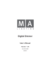
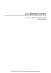
1
English
MDP-1219
12 CH. DIGITAL MODULE DIMMER
Instruction Manual
Contents
General Instructions 1
Features 2
1. Overview 4
1.1 Front View 4
1.2 Rear View 6
1.3 Preview Menu 9
2. Operating Guide 10
General
10
2.1 Top Menu 11
2.2 Channel Menu 14
2.3 Memory Menu 16
2.4 Setup Menu 18
2.4.1 DMX Fail 20
2.4.2 DMX Mode 21
2.4.3 DMX/MIDI Input 21
2.4.4 MIDI Channel 22
2.4.5 Phase Correction 22
2.4.6 User Mode 22
2.4.7 Master/Slave Mode 23
MDP-1219
12 CH. DIGITAL MODULE DIMMER
Improvement and changes to
specifications, design and this
manual, may be made at any time
without prior notice.
All rights reserved.
2.4.8 Unit NO. 23
2.4.9 User Curve 23
2.4.10 Clear Curves 25
2.4.11 Delete All 26
3. Troubleshooting 27
Technical Specifications
28
General Instructions
Thank you for your purchase. Please read the following instructions
before using your new unit. After being read thoroughly, this manual
shall be kept with the fixture for future reference.
CAUTION!
Every unit is thoroughly tested and shipped in perfect
condition. Carefully unpack the unit and inspect
equipment for shipping damage.
This fixture is not intended for home use.
Do not make any inflammable liquids, water or metal
objects enter this unit.
There are no user-serviceable parts inside. Do not take
the metal housing apart.
Servicing must be conducted by qualified service
personnel.
!
This product must be earthed.
WARNING
Never operate unit when case is open.
To prevent the risk of fire or electric shock , do not
expose this appliance to high temperature or humidity.
After you've set up the wiring connection, remember to
replace the back cover and seal up the wiring holes so
that the cooling fan can blow the heat out.
Always disconnect the MDP-1219 from main power
before servicing unit , there may be high voltage inside
console.
1
MDP-1219
Instructions page 1
1
Features
Section 1
GENERAL FEATURES
The MDP-1219 is a 12 channel digital module dimmer, which contains a
32-bit high power computer with a Time Processing Unit and a big graphic
display. This advanced technology offers possibilities of new and
satisfactory operation.
Each unit features as follows:
Ease of operation due to multi-option menu and clear menu
Separate DMX addressing for each channel
Each channel can be programmed with DMX address, a control curve
the limitation, the preheat of the lamps and the loadcheck.
Free programming of control curves
12 internal storable memories with cross-fade
Each chase consisting of a series of memories can be programmed
with chase speed, fade time and up to 12 steps.
DMX off /DMX failures can start a chase or call up a memory
Operations can be locked while DMX or analogue input works
normally as before
DMX and MIDI input can be selectable
Electric fuse and load check.
Several units can be linked using Master/Slave mode
Overvoltage and overtemperature warning with switch off
Indication of incoming/outgoing signals, phase voltage, internal
memories, etc. by the LCD display.
1
1 2
MDP-1219 Instructions page
Features
Section 2
DETAILED FEATURES
The MDP-1219 works with the phase angle control method with SCRs.
This method produces disturbance especially in the lower frequency range.
The disturbance will be filtered by using interference suppression filters.
The heat produced by SCRs will be blown out by an electric fan.
The short circuit protection for each channel is achieved by a high-quality
magnetic circuit breaker and SCRs with 1000A peak current capacity.
Built-in DMX512,analogue input voltage(0~10V) and load outputs allow
different applications.
About Fan Cooling
The unit's fan is used to dissipate the heat so that this unit can work in
a perfect condition.
When the power is turned on, the cooling fan will automatically run.
When the power is turned off, it will stop.
Attention!
After you've set up the wiring connection, remember to replace the
back cover and seal up the wiring holes so that the cooling fan can
blow the heat out.
MDP-1219 Instructions page 3
1. Overview
1.1 Front View
1
2 3 4
5
6
Channel dimmer module
3
MDP-1219 Instructions page 4
1. Overview
1.1 Front View
1
LCD DISPLAY
Used to display various menus and submenus.
2
THE LEFT BUTTON
3
THE MIDDLE BUTTON
The three "basic menus" can be selected one after the other by this
middle button.
4
THE RIGHT BUTTON
5
THE ENCODER
The encoder can be turned with or without simultaneously pressing a
button; the functions will be different in the various menus.
Programming is only possible by pressing a button and turning the
encoder at the same time.
6
THE CHANNEL DIMMER MODULE (x12)
The channel dimmer module is incorporated with a 10A circuit breaker
and SCRs with 1000A peak current capacity. The removable, plug &
play module enables easy and flexible setup of 12 channel module.
3
MDP-1219
Instructions page 5
1. Overview
1.2 Rear View
3
1=Ground
2=Data3=Data+
6
DMX IN
2
ANALOG IN
DC 0V~10V
2
DMX OUT
1
1
3
2
1
1=Ground
2=Data3=Data+
MIDI
3
LINK IN
MIDI
4
LINK THRU
5
LINK OUT
23-001-0841
3
MDP-1219 Instructions page 6
1. Overview
1.2 Rear View
1
DMX IN
Receives DMX signal
2
DMX OUT
Sends DMX signal out
3
MIDI/LINK IN
Receives MIDI/LINK Message
4
MIDI/LINK THROUGH
Switch-through MIDI/LINK Message
5
LINK OUT
Sends LINK message out
6
ANALOG IN
Receives analog signal
3
MDP-1219
Instructions page 7
1. Overview
1.2 Rear View
For proper connection, please refer to the below wiring diagram printed
on the top cover.
POWER INPUT: ............................... AC 120V~50-60Hz
POWER INPUT: ............................... AC 120V~50-60Hz
3
MDP-1219 Instructions page 8
1. Overview
1.3 Preview Menu
DMX
CUR
1
2
3
4
5
6
7
8
9
10
11
12
1
2
3
4
5
6
7
8
9
10
11
12
-
PRE
LTM
15
30
100
100
100
100
100
100
100
100
100
100
100
-
1
%
LC
30
MENU
<<
OFF
CHASE
00
%
00
SEC
000.1
MEMORY
1
2
1
2
3
4
5
6
7
8
9
10 11 12
6
7
8
9
10 11 12
OUT MEM
00
<<
MENU
<<
SAVE
3
MDP-1219
Instructions page 9
3
4
5
000.1
<<
Memory Menu
Chase Menu
20
** MEMORIES
STEPS
SPEED
No
<<
**CHASE
FADE
25%
MENU
CHA
MENU
CHA.1
SET
GO
MENU
<<
Curve Menu
INPUT 00 %
SAVE
DMX
Value
1
Channel Menu
.................
241
<<
.................
OUT
PUT
00
%
L3
225
--%
Value
<<
** SETUP CURVE
<<
MANUAL
<<
MENU
L2
237
CHA.
OFF
Ver:1.0
<<
L1
1 2 3 4 5 6 7 8 9 10 11 12
<<
DMX FAIL
OFF
DMX MODE BLOCK
MIDI/DMX
DMX
MIDI CHANNEL
01
--------------------------------PHASE CORR.
YES
USER
MODE
SUPER
MASTER/SLAVE
MASTER
UNIT
No
01
CURVE
USER1
EDIT
CURVE
USER2
EDIT
--------------------------------CLEAR CURVES CLEAR
DELETE ALL
DELETE
Top Menu
Setup Menu
Press Menu button for 5 seconds
6
2. Operating Guide
General
The LCD display is integrated with this 12 Channel Digital Module Dimmer.
Three buttons under the display and an Encoder (Data Wheel) make all
necessary adjustments possible for example DMX address, limitation,
control curves, preheat ,etc.
Working principle of such buttons is :
-- The middle button can lead to each menu.
-- All data are fed into the dimmer by the encoder.
3
MDP-1219 Instructions page610
2. Operating Guide
2.1 Top Menu
Functions:
1. After "Power On", "Top Menu" is automatically shown in the display.
2. This menu is the standard menu. All statuses, messages and input of
the channel s can be displayed within it.
3. In this menu, the channels can be set to the definable values.
CAUTION:
Attentions shall be taken to each item below:
When this product is used for the first time, you'd better not input DMX or
Analogue,or set each channel as "0".
Without setting, Analogue input can be used directly.
When using DMX512, set DMX address according to the relevant menus.
DMX can be set by pressing the left or the right button. This can also be
achieved by turning the encoder without touching any button
To select the desired menu, tap the middle button. The menu pictures will
occur alternately.
Programming parameters by touching the left and right buttons, or turning
the encoder while not holding down the left and right buttons.
This product has three basic menus, a functional menu, a Chase menu
and two Curve menus. These menus can be switched over by pressing
the middle button or the left and right button.
3MDP-1219 Instructions page 11
6
2. Operating Guide
2.1 Top Menu
Top Menu
OPERATION
1
L1
237
L2
L3
225
241
1 2 3 4 5 6 7 8 9 10 11 12
2
3
4
5
6
7
11
MEMORY 1
MANUAL
Value
--%
DMX
Value
1
SET
CHA.
CHA.1
10
25%
20
%
MENU
8
9
1 Voltage measurement of the 3 phases L1, L2 and L3.
2 Input monitor of channel 1 (here: external 80%)
3 Input monitor of channel 1 (here: internal 50%)
4 Load check: load disconnected
5 Load check: load connected
6 Load check is not activated.
7 Hold down the left button, turn the encoder simultaneously, then the
corresponding value of the channel will be varied.
3
MDP-1219 Instructions page612
2. Operating Guide
2.1 Top Menu
8 A short touch sets selected channel(1) to predefined value(e.g.20%).
Tapping again will switch it off. While holding down the right button, turn
the encoder(Data Wheel),this value will be stored after switchover.
9 Temporarily turn the encoder to select one of 12 channels.
10 If DMX signal is received, both the channel in which DMX data alters
and the value after being changed will be indicated. If no DMX signal
received,"NO DMX" is displayed. When selected, MIDI is indicated.
11 Temporarily adjusts internal patterns.
ADDITION:
1. Hold down the right button,"CLEAR ALL" appears at the left corner of
the LCD display. Once you tap the right button, all temporary settings for
each channel are to be deleted.
2. Particular attentions shall be taken to that:
The settings of the channels will not be stored permanently and not be
recalled after power off. Please use the internal Memories .
3
MDP-1219
Instructions page 13
6
2. Operating Guide
2.2 Channel Menu
4
5
6
7
8
9
1
NO
DMX
1
2
3
4
5
6
7
8
9
10
11
12
1
2
3
4
5
6
7
8
9
10
11
12
CHA
<<
2
3
CUR
PRE
LTM
-
15
30
100
100
100
100
100
100
100
100
100
100
100
-
Cu1
Cu2
SW
-
1
LC
14
16
15
30%
MENU
<<
Channel Menu
11
12
10
13
OPERATION
1 The shade is the cursor.
2 Preheat set to 15%.
3 Channel 1 limited to 30%. All others have no limits (100%).
4 Selected Channel (Encoder)
5 DMX address for channel 4
6 Control curve "Curve 1"
7 Control curve "Curve 2"
8 Switch status
3
MDP-1219 Instructions page614
2. Operating Guide
2.2 Channel Menu
OPERATION
9 Control curve "linear"
10 Touch the left button and turn the encoder simultaneously, the cursor
moves horizontally. Then DMX, Curve, Limit and the like will be
selected.
11 Menu button leads to the 3rd menu(Memory menu).
Exception: When the Dimmer is just working in " normal user " mode,
the button switches back to the Top menu.
12 Holding down the right button and simultaneously turn the encoder set
DMX address, types of Curves and the like.
13 One of 12 channels can be selected by turning the encoder without
touching any button.
14 When no load is connected, an " " is indicated.
15 Shows that load is connected.
16 Small rectangle denotes that load check is switched off.
Additional
This menu always appears after the Top Menu when the middle button is
pressed.
For each channel in this menu, the DMX address, a control curve,
the limitation,the preheat of the lamps and the load check is programmed.
Procedure: The encoder selects one channel (1...12). In the LCD display,
the cursor is moving up and down vertically.
While holding down the left button, turn the encoder, the cursor will move
in the horizontal direction. Now "DMX address", "Curve", "Limit" ,etc.,can
be selected.
Press the right button and turn the encoder simultaneously,the actual value
can be changed.
3
MDP-1219
Instructions page 15
6
2. Operating Guide
2.3 Memory Menu
General
This menu appears after the Channel Menu. Once the Menu button is
pressed, this menu is activated, provided the supervisor mode is activated.
In this menu, a total of 12 internal memories can be stored and recalled.
In addition, the a chase can be selected. The running speed, fade time
and the number of steps can be programmed. The number of chase steps
is limited to 12, and each step is stored into the corresponding internal
memory in advance.
OPERATION
Memory Menu
** MEMORIES
1
2
OFF
CHASE
MEMORY
1
2
3
4
5
6
7
8
9
10 11 12
8
3
OUT MEM
1
2
3
4
5
6
7
8
9
10 11 12
7
<<
GO
MENU
<<
4
000.1
5
6
3
6 16
MDP-1219 Instructions page
2. Operating Guide
2.3 Memory Menu
OPERATION
1 Preselect no internal memory and chaser turns off.
2 Preselect chaser, which turns on.
3 Preselect output pattern.
4 When " CHASE" is not selected by the cursor, pressing the left button
and turning the encoder simultaneously changes the cross-fade time
within the extent of 0.0 to 999.9.
Exception :
When the chase is selected by the cursor, "EDIT" is displayed at the right
corner where cross-fade time is indicated. If now the left button is pressed,
Chaser edit menu is displayed . It is a submenu of the Memory menu.
Here 3 chaser parameter can be programmed:
- "Speed" (interval between steps) 0.1~999 seconds.
- "Fade" (cross-fade time) 0~100%.
- "Steps" (number of steps) 0~12.
5 Turning the encoder without pressing any button selects OFF, CHASE
and MEMORY 1~12.
6 This button will recall the selected MEMORY, CHASE or OFF function.
7 Built-in or external control signal, for example that Dimming level of
CH 12 is 50%.
8 Indication of MEMORY1~12, for example that Dimming level of CH 12 is
50%.
3
MDP-1219
Instructions page 17
6
2. Operating Guide
2.3 Memory Menu
ATTENTION!
When MEMORY is selected by the cursor, touch the left button, then
"STORE" is indicated at the right corner. Press the right button again,
dimming levels of all channels will be stored permanently by the dimmer.
2.4 Setup Menu
General
General
This menu can be achieved by pressing the Menu button for a
minimum of 5 seconds.
In this menu, very important parameters used for controlling the
operation of the dimmer can be selected and set.
Turn the encoder without pressing any button, the cursor will move up
and down vertically to select different lines.
While holding down the right button, turn the encoder, then different
functions can be selected or started in that line preselected by the
cursor.
3
6 18
MDP-1219 Instructions page
2. Operating Guide
2.4 Setup Menu
Setup Menu
DMX FAIL
OFF
DMX MODE BLOCK
MIDI/DMX
DMX
MIDI CHANNEL
01
--------------------------------PHASE CORR.
YES
USER
MODE
SUPER
MASTER/SLAVE
MASTER
UNIT
No
01
CURVE
USER1
EDIT
CURVE
USER2
EDIT
--------------------------------CLEAR CURVES CLEAR
DELETE ALL
DELETE
OFF
<<
1
MENU
4
<<
Ver:1.0
2
3
OPERATION
1 Once press the Menu button, this menu switches back to the Top Menu.
2 Tap the right button and turn the encoder simultaneously, the
parameters on the right of the item selected alter continually. A big
character at the right corner displays the corresponding item selected.
3
MDP-1219
Instructions page 19
6
2. Operating Guide
2.4 Setup Menu
OPERATION
3 Turn the encoder without tapping any button, the cursor moves up and
down, selecting the desired item to set the parameters.
4 When USER CURVE is selected, press this button, you can enter
Curve edit menu.
2.4.1 DMX Fail
Here the reaction to failing DMX signal can be programmed
- HOLD : holds the last received DMX signal until a new DMX signal
reaches the dimmer.
- OFF :
holds the last received DMX signal for 1 second and then
switches off. The analogue input(0~10V) will be switched off,
when a valid DMX signal is received.
- CHA 1s :
starts the internal chase after waiting for 1 second.
- M1
1s :
calls the internal memory No.1 after waiting for 1 second.
- M2
1s :
calls the internal memory No.2 after waiting for 1 second.
Note : Calling of other memories is the same as above.
- CHA
9s : starts the internal chase after waiting for 9 seconds.
- M1
9s : calls the internal memory No.1 after waiting for 9 seconds.
- M2
9s : calls the internal memory No.2 after waiting for 9 seconds.
Note: That other memories are called is similar to that described above.
The actual status will be displayed in the Top Menu (message : " NO DMX")
CHASE
3
MDP-1219 Instructions page 20
6
2. Operating Guide
2.4 Setup Menu
2.4.2 DMX Mode
Here " Block", "Single" and "2 CHA" can be selected.
- SINGLE : means that the DMX address of each channel is selectable,
and even that the 12 channels can select the same DMX
addresses.
- Block :
means that the complete dimmer(12 channels) has only one
start address.
-2 CHA :
means that the 2-channel switch-mode is active. This mode is
necessary, if only 2 single DMX channels control all 12 dimmer
channels.
Mode of operation:
64 different combinations for the first DMX channel control
channels No.1~6; The 2nd DMX channel controls the dimmer
channels 7~12.
2.4.3 DMX /MIDI Input
Here DMX
the digital
serial input can be selected : DMX-512 or MIDI.
2.4.3
MIDI
MIDI only accepts " program change" commands . Other commands are
neglected. MIDI is intended for controlling and calling up 12 internal
MEMORIES, CHASE or OFF. In MIDI status, the external analogue
commands will be activated.
3
MDP-1219
Instructions page 21
6
2. Operating Guide
2.4 Setup Menu
2.4.4 MIDI Channel
A total of channels 1~16 can be selected.
2.4.5 Phase Correction
Usually this control parameter is set to "ON". It makes a brightness-linear
control possible. The normal non-linearity, produced by the SRC's phase
angle control, is thereby compensated. This function works in addition to
the " USER CURVES".
2.4.6 USER MODE
With this function the dimmer function can be cut down in 3 steps.
-SUPER :
"Supervisor" means that all functions can be used.
-NORM :
"Normal User" means that in the Channel Menu, only the
DMX address can be programmed. The Memory Menu is
switched off. After having tested the dimmer functions,
the user shall use this mode, which helps protect the
parameters set by the dimmer. The DMX address shall be
programmable.
- LOCK :
The dimmer is completely locked and can be not be
operated with the buttons or encoder. To change this mode,
press the middle button because it allows the entry into the
Setup Menu by pressing it for 5 seconds.
3
MDP-1219 Instructions page 6
22
2. Operating Guide
2.4 Setup Menu
2.4.7 Master/ Slave Mode
Several units can be linked in Master/Slave mode. The master and slave unit
must be defined when linking. The master unit only can send information out,
and the slave unit only receives information. In the linkup of several units,
only one master unit can be selected. The dimmers are not required to transmit
information each other. All of them shall be set as the master parts or slave parts.
2.4.8 Unit Number
Not used now. It is prepared for the new DMX form or standard revised
or self-defined by manufacturer.
2.4.9 User Curve
Here the setup menu for USER CURVE 1 or 2 can be activated by
pressing the left button once.
Two individual brightness curves can be programmed. These curves can
be assigned to the dimmer channels.
Turn the encoder without pressing any button, input data changes within
0%~FF%(100%). At this time, the horizontal cursor changes back and
forth.
Holding down the right button and turning the encoder simultaneously
makes the output data change between 0% and FF%(100%).
3
MDP-1219 Instructions page 23
6
2. Operating Guide
2.4 Setup Menu
2.4.9 User Curve
OUTPUT
There are five types of curves below for reference.
1. Here the connection between input and
output is linear, which is applicable to some
linear loads.
OUTPUT
INPUT
2. The output reacts even at low input values.
OUTPUT
INPUT
3. The output reacts very little to small inputs,
but all the more when the input is higher.
INPUT
3
MDP-1219 Instructions page 624
2. Operating Guide
2.4 Setup Menu
OUTPUT
2.4.9 User Curve
4. The output does not react until input
exceeds 40%.
INPUT
OUTPUT
40
5. If the input is 0%, the output is activated to
100%; if input is 100%, the output is 0%.
INPUT
2.4.10 Clear Curves
Deletes both USER CURVES. Therefore the cursor is set on this line, the
right button is pressed and the encoder turned simultaneously.
Attention!
Once this function is implemented, the programmed curves will be deleted
and not be recalled. Be careful using this function, because it may impair
the loads.
3
MDP-1219
Instructions page 25
6
2. Operating Guide
2.4 Setup Menu
2.4.11 Delete All
"DELETE ALL" deletes all memories, chases, DMX addresses, curves, etc.,
which is carried out by turning the encoder while holding the right button.
Attention!
All data will be deleted and reprogrammed ! Be careful in using this
function.
3
MDP-1219 Instructions page626
3. Troubleshooting
Before you call for service, determine the symptoms and make a few
simple checks as follows.
Symptoms
Checks
The cooling fan doesn't work,
and the LCD goes out.
The power is not correctly connected
or power failure occurs.
The channel output is off at times.
Bad connection between the channel
dimmer module and the channel output,
try to pull out the channel dimmer module
and plug it several times to assure proper
connection.
3
MDP-1219
Instructions page 27
Technical Specifications
Power Input.... ...............................................................AC 120V~50/60Hz
Channel Output..............................................10A per channel, Total 120A
(for single-phase connection)
Channel Output................................10A per channel, Total 40A per phase
(for three-phase connection)
Analogue Input........................................................................... DC 0~10V
DMX In/Out................................................... 3 pin female/male XLR socket
MIDI In/Through.....................................................5 pin female DIN socket
Size...................................................................... 482.6mm 177.5mm 436mm
Weight..................................................................................................... 30.8kg
3
MDP-1219 Instructions page 28
24-004-0693
Rev 1.0 August 2001
All rights reserved