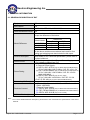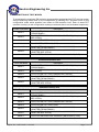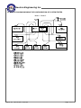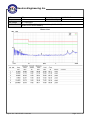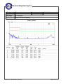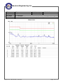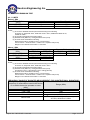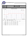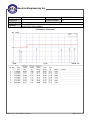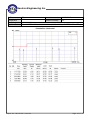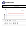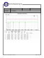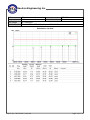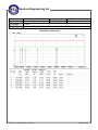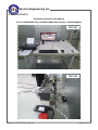
1
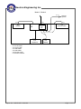
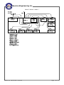
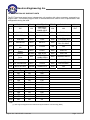
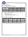
Neutron Engineering Inc.
RV-0000000
FCC Test Report
Jan. 02, 2014
1311149
IPC
AMOS-820; CPT-1000; AMOS-820-P
Issued Date
Project No.
Equipment
Model Name
:
:
:
:
Applicant
Address
: VIA Technologies, Inc.
: 1F, 531, Zhongzheng Rd. Xindian
District, New Taipei City 231 Taiwan
Tested by: Neutron Engineering Inc. EMC Laboratory
Date of Receipt: Nov. 15, 2013
Date of Test: Nov. 15, 2013 ~ Dec. 31, 2013
Te s t i n g E n g i n e e r :
(Pike Lee)
Technical Manager :
(Jeff Yang)
Authorized Signatory :
(Andy Chiu)
Neutron Engineering Inc.
B1, No. 37, Lane 365, YangGuang St.,
NeiHu District 114, Taipei, Taiwan.
TEL: +886-2-2657-3299
FAX: +886-2-2657-3331
Report No.: NEI-FCCE-1-1311149
Page 1 of 77
Neutron Engineering Inc.
RV-0000000
Declaration
Neutron represents to the client that testing is done in accordance with standard procedures as applicable
and that test instruments used has been calibrated with the standards traceable to National Measurement
Laboratory (NML) of R.O.C., or National Institute of Standards and Technology (NIST) of U.S.A.
Neutron's reports apply only to the specific samples tested under conditions. It is manufacture’s
responsibility to ensure that additional production units of this model are manufactured with the identical
electrical and mechanical components. Neutron shall have no liability for any declarations, inferences or
generalizations drawn by the client or others from Neutron issued reports.
Neutron’s reports must not be used by the client to claim product endorsement by the authorities or any
agency of the Government.
This report is the confidential property of the client. As a mutual protection to the clients, the public and
Neutron-self, extracts from the test report shall not be reproduced except in full with Neutron’s authorized
written approval.
Neutron’s laboratory quality assurance procedures are in compliance with the ISO Guide 17025
requirements, and accredited by the conformity assessment authorities listed in this test report.
Limitation
For the use of the authority's logo is limited unless the Test Standard(s)/Scope(s)/Item(s) mentioned in this
test report is (are) included in the conformity assessment authorities acceptance respective.
Report No.: NEI-FCCE-1-1311149
Page 2 of 77
Neutron Engineering Inc.
Table of Contents
RV-0000000
Page
REPORT ISSUED HISTORY
4 1 . CERTIFICATION
5 2 . SUMMARY OF TEST RESULTS
6 2.1 TEST FACILITY
7 2.2 MEASUREMENT UNCERTAINTY
7 3 . GENERAL INFORMATION
8 3.1 GENERAL DESCRIPTION OF EUT
8 3.2 DESCRIPTION OF TEST MODES
9 3.3 BLOCK DIAGRAM SHOWING THE CONFIGURATION OF SYSTEM TESTED 10 3.4 DESCRIPTION OF SUPPORT UNITS
4 . EMC EMISSION TEST
13 14 4.1 CONDUCTED EMISSION TEST
4.1.1 LIMITS
4.1.2 MEASUREMENT INSTRUMENTS LIST
4.1.3 TEST PROCEDURE
4.1.4 DEVIATION FROM TEST STANDARD
4.1.5 TEST SETUP
4.1.6 EUT OPERATING CONDITIONS
4.1.7 TEST RESULTS
14 14 14 15 15 15 16 17 4.2 RADIATED EMISSION TEST
4.2.1 LIMITS
4.2.2 MEASUREMENT INSTRUMENTS LIST
4.2.3 TEST PROCEDURE
4.2.4 DEVIATION FROM TEST STANDARD
4.2.5 TEST SETUP
4.2.6 EUT OPERATING CONDITIONS
4.2.7 TEST RESULTS-BELOW 1 GHZ
4.2.8 TEST RESULTS-ABOVE 1 GHZ
27 27 28 29 30 30 30 31 45 5 . EUT TEST PHOTO
Report No.: NEI-FCCE-1-1311149
59 Page 3 of 77
Neutron Engineering Inc.
RV-0000000
REPORT ISSUED HISTORY
Revised Version No.
-
Description
Initial Issue.
Report No.: NEI-FCCE-1-1311149
Issued Date
Jan. 02, 2014
Page 4 of 77
Neutron Engineering Inc.
RV-0000000
1. CERTIFICATION
Equipment :
Brand Name :
Model Name :
Applicant:
Date of Test :
Sta n d a r d s :
IPC
VIA
AMOS-820; CPT-1000; AMOS-820-P
VIA Technologies, Inc.
Nov. 15, 2013 ~ Dec. 31, 2013
FCC Part 15, Subpart B: 2012 Class A
ICES-003 Issue 5: 2012 Class A
CAN/CSA CISPR 22-10 Class A
CISPR 22: 2008 Class A
ANSI C63.4-2009
The above equipment has been tested and found compliance with the requirement of the relative
standards by Neutron Engineering Inc. EMC Laboratory.
The test data, data evaluation, and equipment configuration contained in our test report (Ref No.
NEI-FCCE-1-1311149) were obtained utilizing the test procedures, test instruments, test sites that
has been accredited by the Authority of TAF according to the ISO-17025 quality assessment
standard and technical standard(s).
Report No.: NEI-FCCE-1-1311149
Page 5 of 77
RV-0000000
Neutron Engineering Inc.
2. SUMMARY OF TEST RESULTS
Test procedures according to the technical standards:
Emission
Standard
Test Item
FCC Part 15,
Conducted emission
Subpart B: 2012
ICES-003 Issue 5: 2012 Radiated emission Below 1 GHz
CAN/CSA CISPR 22-10
Radiated emission Above 1 GHz
CISPR 22: 2008
Limit
Judgment
Class A
PASS
Class A
PASS
Class A
PASS
Remark
NOTE (2)
NOTE:
(1) ”N/A” denotes test is not applicable in this Test Report.
(2) If the EUT’s max operating frequency does not exceed 108 MHz, the test will not be performed.
Report No.: NEI-FCCE-1-1311149
Page 6 of 77
RV-0000000
Neutron Engineering Inc.
2.1 TEST FACILITY
The test facilities used to collect the test data in this report:
Conducted emission Test:
C03: (VCCI RN: C-4461)
B1, No. 37, Lane 365, YangGuang St., NeiHu District 114, Taipei, Taiwan.
Radiated emission Test (Below 1 GHz):
OS02: (VCCI RN: R-2669; FCC RN: 95335; FCC DN: TW1010)
No.132-1, Ln. 329, Sec. 2, Balian Rd., Xizhi Dist., New Taipei City 221, Taiwan (R.O.C.)
Radiated emission Test (Above 1 GHz):
CB08: (VCCI RN: G-91; FCC RN: 614388; FCC DN: TW1054; IC Assigned Code: 4428C-1)
1F., No. 61, Ln. 77, Sing-ai Rd., Neihu Dist., Taipei City 114, Taiwan (R.O.C.)
2.2 MEASUREMENT UNCERTAINTY
The measurement uncertainty is not specified by FCC/ Industry Canada rules and for
reference only.
The reported uncertainty of measurement y ± U,where expended uncertainty U is based on a
standard uncertainty multiplied by a coverage factor of k=2,providing a level of confidence of
approximately 95%.
The measurement instrumentation uncertainty considerations contained in CISPR 16-4-2.
A. Conducted emission test:
Test Site
Measurement Frequency Range
C03
150 kHz ~ 30 MHz
B. Radiated emission test:
Measurement Frequency
Test Site
Range
30 MHz ~ 200 MHz
30 MHz ~ 200 MHz
OS02
200 MHz ~ 1, 000 MHz
200 MHz ~ 1, 000 MHz
Test Site
Item
CB08
Radiated
emission at
3m
Ant.
H/V
V
H
V
H
Measurement Frequency Range
30 - 200MHz
200 - 1000MHz
Horizontal
Polarization
1 - 18GHz
18 - 40GHz
30 - 200MHz
200 - 1000MHz
Vertical
Polarization
1 - 18GHz
18 - 40GHz
U,(dB)
1.94
NOTE
U,(dB)
NOTE
2.48
2.16
2.50
2.66
Uncertainty
3.35 dB
3.11 dB
3.97 dB
4.01 dB
3.22 dB
3.24 dB
4.05 dB
4.04 dB
NOTE
Our calculated Measurement Instrumentation Uncertainty is shown in the tables above.
These are our Ulab values in CISPR 16-4-2 terminology.
Since Table 1 of CISPR 16-4-2 has values of measurement instrumentation uncertainty,
called UCISPR, as follows:
Conducted Disturbance (mains port) – 150 kHz – 30 MHz : 3.6 dB
Radiated Disturbance (electric field strength on an open area test site or alternative test
site) – 30 MHz – 1000 MHz : 5.2 dB
It can be seen that our Ulab values are smaller than UCISPR.
Report No.: NEI-FCCE-1-1311149
Page 7 of 77
RV-0000000
Neutron Engineering Inc.
3. GENERAL INFORMATION
3.1 GENERAL DESCRIPTION OF EUT
Equipment
IPC
Brand Name
VIA
Model Name
AMOS-820; CPT-1000; AMOS-820-P
OEM Brand/Model Name N/A
There are three models based on similar electrical circuit
except the difference of list below:
Model Name
Model Difference
Product Description
Power Source
Power Rating
Connecting I/O Port(s)
Products Covered
EUT Modification(s)
AMOS-820
AMOS-820-P
CPT-1000
Differences
Power Board
POE
X
X
X
O
O
O
All the above models were evaluated and used for final
testing and collecting test data included in this report.
The EUT is an IPC.
More details of EUT technical specification, please refer to
the User's Manual.
A. DC Voltage supplied from External Power Supply.
B. DC Voltage supplied from PoE.
A. 1. EUT Rating: I/P DC 12V
2. External Power Supply:
(1) DELTA, ADP-18TB A (only for AMOS-820 and AMOS-820-P)
I/P: AC 100-240V 0.6A 50-60Hz / O/P: DC 12V 1.5A
(2) FSP, FSP060-DBAB1 (only for AMOS-820 and AMOS-820-P)
I/P: AC 100-240V 1.5A 50-60Hz / O/P: DC 12V 5A
MAX (60W MAX)
(3) DELTA, ADP-36JH B (only for CPT-1000)
I/P: AC 100-240V 1A 50-60Hz / O/P: DC 12V 3A
B. PoE: I/P DC 48V(only for CPT-1000 and AMOS-820-P)
Please refer to the User's Manual
1 * CPU: 1.0GHz Freescale i.MX 6Quad ARM Cortex-A9
1 * RAM: 1GB DDR3
1 * External Power Supply:
(1) DELTA, ADP-18TB A (only for AMOS-820 and AMOS-820-P)
(2) FSP, FSP060-DBAB1(only for AMOS-820 and AMOS-820-P)
(3) DELTA, ADP-36JH B (only for CPT-1000)
N/A
Note:
1. For a more detailed features description, please refer to the manufacturer’s specifications or the User's
Manual.
Report No.: NEI-FCCE-1-1311149
Page 8 of 77
RV-0000000
Neutron Engineering Inc.
3.2 DESCRIPTION OF TEST MODES
To investigate the maximum EMI emission characteristics generates from EUT, the test system
was pre-scanning tested base on the consideration of following EUT operation mode or test
configuration mode which possible have effect on EMI emission level. Each of these EUT
operation mode(s) or test configuration mode(s) mentioned above was evaluated respectively.
Pretest Test Mode
Mode 1
Mode 2
Description
FULL SYSTEM HDMI 1920*1080/60Hz(AMOS-820) (Adapter :
FSP060-DBAB1)
FULL SYSTEM HDMI 1920*1080/60Hz(AMOS-820) (Adapter :
ADP-18TB A)
Mode 3
FULL SYSTEM (CPT-1000) (Adapter:ADP-36JH B)
Mode 4
FULL SYSTEM (CPT-1000) (PoE)
Mode 5
Mode 6
Mode 7
FULL SYSTEM HDMI 1920*1080/60Hz (AMOS-820-P)
(ADAPTER:FSP060-DBAB1)
FULL SYSTEM HDMI 1920*1080/60Hz (AMOS-820-P)
(ADAPTER:ADP-18TB A)
FULL SYSTEM HDMI 1920*1080/60Hz (AMOS-820-P) (PoE)
Conducted emission test
Final Test Mode
Mode 1
Mode 2
Mode 3
Mode 5
Mode 6
Description
FULL SYSTEM HDMI 1920*1080/60Hz(AMOS-820) (Adapter :
FSP060-DBAB1)
FULL SYSTEM HDMI 1920*1080/60Hz(AMOS-820) (Adapter :
ADP-18TB A)
FULL SYSTEM (CPT-1000) (Adapter:ADP-36JH B)
FULL SYSTEM HDMI 1920*1080/60Hz (AMOS-820-P)
(ADAPTER:FSP060-DBAB1)
FULL SYSTEM HDMI 1920*1080/60Hz (AMOS-820-P)
(ADAPTER:ADP-18TB A)
Radiated emission test
Final Test Mode
Mode 1
Mode 2
Description
FULL SYSTEM HDMI 1920*1080/60Hz(AMOS-820) (Adapter :
FSP060-DBAB1)
FULL SYSTEM HDMI 1920*1080/60Hz(AMOS-820) (Adapter :
ADP-18TB A)
Mode 3
FULL SYSTEM (CPT-1000) (Adapter:ADP-36JH B)
Mode 4
FULL SYSTEM (CPT-1000) (PoE)
Mode 5
Mode 6
Mode 7
FULL SYSTEM HDMI 1920*1080/60Hz (AMOS-820-P)
(ADAPTER:FSP060-DBAB1)
FULL SYSTEM HDMI 1920*1080/60Hz (AMOS-820-P)
(ADAPTER:ADP-18TB A)
FULL SYSTEM HDMI 1920*1080/60Hz (AMOS-820-P) (PoE)
Report No.: NEI-FCCE-1-1311149
Page 9 of 77
Neutron Engineering Inc.
RV-0000000
3.3 BLOCK DIAGRAM SHOWING THE CONFIGURATION OF SYSTEM TESTED
Mode 1 / Mode 2
Report No.: NEI-FCCE-1-1311149
Page 10 of 77
RV-0000000
Neutron Engineering Inc.
Mode 3 / Mode 4
C-1
C-8
E-8
Modem
C-12
E-1
EUT
C-4
E-4
Keyboard
Remote
System
C-3
E-3
DVD PLAYER
E-12
Mico
SD
C-5
E-5
Mouse
C-1 RJ-45 Cable
C-3 Video Cable
C-4 USB Cable
C-5 USB Cable
C-8 RS-232 Cable
C-12 Power Cable*9
Report No.: NEI-FCCE-1-1311149
Page 11 of 77
Neutron Engineering Inc.
RV-0000000
Mode 5 / Mode 6 / Mode 7
Report No.: NEI-FCCE-1-1311149
Page 12 of 77
RV-0000000
Neutron Engineering Inc.
3.4 DESCRIPTION OF SUPPORT UNITS
The EUT has been tested as an independent unit together with other necessary accessories or
support units. The following support units or accessories were used to form a representative test
configuration during the tests.
Item
Equipment
Brand
E-1
IPC
VIA
E-2
24” LCD Monitor
E-3
FCC ID
Series No.
Note
N/A
N/A
EUT
DELL
Model/Type No.
AMOS-820;
CPT-1000;
AMOS-820-P
2408WFPb
DOC
071863-11
CD/DVD Player
SONY
DVP-NS975V
N/A
E-4
USB K/B
DELL
L50U
DOC
E-5
USB Mouse
DELL
MS111-L
DOC
2030851 14W
CN-0H9F99-65890
-17P-06WP-A01
CN-09RRC7-44
751-17J-OH1F
CJ-323
N/A
N/A
HV04T
DOC
95NY781
DM-1414V
WDBACW00
10HBK-SESN
VCVRA-1004
DOC
8041708
DOC
WCAV5J749731
DOC
CN17511HHK
CN-OJ257M-72
872-09J-067L
N/A
E-6
E-7
E-8
E-9
E-10
Compact Earphone
CJ
Mic
USB Flash/MP3
DELL
Player
Modem
ACEEX
3.5” External Hard
WD
Drive
Printer
HP
E-11
24” LCD Monitor
DELL
U2410f
DOC
E-12
Micro SD Card
Sandisk
SDSDQ-512
DOC
Item
Shielded Type
Ferrite Core
Length
C-1
NO
NO
10M
C-2
YES
NO
1.8M
C-3
NO
NO
1.5M
C-4
YES
NO
1.7M
C-5
YES
NO
1.7M
C-6
NO
NO
1.8M
C-7
NO
NO
1.7M
C-8
YES
NO
1.7M
C-9
YES
NO
1.2M
C-10
YES
NO
1.7M
C-11
YES
NO
1.7M
C-12
NO
NO
1M
Note
Note:
(1) The support equipment was authorized by Declaration of Conformity (DOC).
Report No.: NEI-FCCE-1-1311149
Page 13 of 77
RV-0000000
Neutron Engineering Inc.
4. EMC EMISSION TEST
4.1 CONDUCTED EMISSION TEST
4.1.1 LIMITS (FREQUENCY RANGE 150 KHZ-30MHZ)
Class A (dBuV)
Class B (dBuV)
FREQUENCY
(MHz)
Quasi-peak
Average
Quasi-peak
Average
0.15 - 0.5
79.00
66.00
66 - 56 *
56 - 46 *
0.50 - 5.0
73.00
60.00
56.00
46.00
73.00
60.00
60.00
50.00
5.0 - 30.0
NOTE:
(1) The tighter limit applies at the band edges.
(2) The limit of " * " marked band means the limitation decreases linearly with the logarithm of the
frequency in the range.
(3) The test result calculated as following:
Measurement Value = Reading Level + Correct Factor
Correct Factor = Insertion Loss + Cable Loss + Attenuator Factor(if use)
Margin Level = Measurement Value – Limit Value
4.1.2 MEASUREMENT INSTRUMENTS LIST
Item Kind of Equipment
Manufacturer
Type No.
Serial No.
Calibrated until
1
TWO-LINE
V-NETWORK
R&S
ENV216
101051
Jun. 16, 2014
2
Test Cable
TIMES
CFD300-NL
C03
Jun. 16, 2014
3
EMI Test Receiver
Measurement
Software
R&S
ESCI
EZ_EMC
(Version NB-03A)
100080
Apr. 01, 2014
N/A
N/A
4
EZ
Remark: “N/A” denotes No Model Name, No Serial No. or No Calibration specified.
Report No.: NEI-FCCE-1-1311149
Page 14 of 77
RV-0000000
Neutron Engineering Inc.
4.1.3 TEST PROCEDURE
a. The EUT was placed 0.8 meters from the horizontal ground plane with EUT being connected
to the power mains through a line impedance stabilization network (LISN). All other support
equipments powered from additional LISN(s). The LISN provide 50 Ohm/ 50uH of coupling
impedance for the measuring instrument.
b. Interconnecting cables that hang closer than 40 cm to the ground plane shall be folded back
and forth in the center forming a bundle 30 to 40 cm long.
c. I/O cables that are not connected to a peripheral shall be bundled in the center. The end of the
cable may be terminated, if required, using the correct terminating impedance. The overall
length shall not exceed 1 m.
d. LISN at least 80 cm from nearest part of EUT chassis.
e. For the actual test configuration, please refer to the related Item –EUT Test Photos.
NOTE:
a. Reading in which marked as Peak, QP or AVG means measurements by using are Quasi-Peak or
Average Mode with Detector BW=9 kHz (6 dB Bandwidth).
b. All readings are Peak Mode value unless otherwise stated QP or AVG in column of Note. If the
Peak or QP Mode Measured value compliance with the QP Limits and lower than AVG Limits, the
EUT shall be deemed to meet both QP & AVG Limits and then only Peak or QP Mode was
measured, but AVG Mode didn‘t perform.
4.1.4 DEVIATION FROM TEST STANDARD
No deviation
4.1.5 TEST SETUP
Vertical Reference Ground Plane
40 cm
EUT
Test Receiver
80 cm
LISN
Horizontal Reference Ground Plane
Report No.: NEI-FCCE-1-1311149
Page 15 of 77
Neutron Engineering Inc.
RV-0000000
4.1.6 EUT OPERATING CONDITIONS
The EUT exercise program used during radiated and/or conducted emission measurement was
designed to exercise the various system components in a manner similar to a typical use. The
program contained on a PC hard disk and is auto-starting on power-up. Once loaded, the program
sequentially exercises each system component in turn.
As the keyboard and mouse are strictly input devices, no data is transmitted to (from) them during
test. They are, however, continuously scanned for data input activity.
Report No.: NEI-FCCE-1-1311149
Page 16 of 77
Neutron Engineering Inc.
RV-0000000
4.1.7 TEST RESULTS
EUT
Temperature
Test Voltage
Test Mode
IPC
Model Name
AMOS-820
24°C
Relative Humidity
48%
AC 120V/60Hz
FULL SYSTEM HDMI 1920*1080/60Hz(AMOS-820) (Adapter : FSP060-DBAB1)
Phase: Line
Report No.: NEI-FCCE-1-1311149
Page 17 of 77
Neutron Engineering Inc.
EUT
Temperature
Test Voltage
Test Mode
RV-0000000
IPC
Model Name
AMOS-820
24°C
Relative Humidity
48%
AC 120V/60Hz
FULL SYSTEM HDMI 1920*1080/60Hz(AMOS-820) (Adapter : FSP060-DBAB1)
Phase: Neutral
Report No.: NEI-FCCE-1-1311149
Page 18 of 77
Neutron Engineering Inc.
EUT
Temperature
Test Voltage
Test Mode
RV-0000000
IPC
Model Name
AMOS-820
24°C
Relative Humidity
48%
AC 120V/60Hz
FULL SYSTEM HDMI 1920*1080/60Hz(AMOS-820) (Adapter : ADP-18TB A)
Phase: Line
Report No.: NEI-FCCE-1-1311149
Page 19 of 77
Neutron Engineering Inc.
EUT
Temperature
Test Voltage
Test Mode
RV-0000000
IPC
Model Name
AMOS-820
24°C
Relative Humidity
48%
AC 120V/60Hz
FULL SYSTEM HDMI 1920*1080/60Hz(AMOS-820) (Adapter : ADP-18TB A)
Phase: Neutral
Report No.: NEI-FCCE-1-1311149
Page 20 of 77
RV-0000000
Neutron Engineering Inc.
EUT
Temperature
Test Voltage
Test Mode
IPC
Model Name
24°C
Relative Humidity
AC 120V/60Hz
FULL SYSTEM (CPT-1000) (Adapter:ADP-36JH B)
CPT-1000
48%
Phase: Line
Report No.: NEI-FCCE-1-1311149
Page 21 of 77
RV-0000000
Neutron Engineering Inc.
EUT
Temperature
Test Voltage
Test Mode
IPC
Model Name
24°C
Relative Humidity
AC 120V/60Hz
FULL SYSTEM (CPT-1000) (Adapter:ADP-36JH B)
CPT-1000
48%
Phase: Neutral
Report No.: NEI-FCCE-1-1311149
Page 22 of 77
Neutron Engineering Inc.
EUT
Temperature
Test Voltage
Test Mode
RV-0000000
IPC
Model Name
AMOS-820-P
24°C
Relative Humidity
48%
AC 120V/60Hz
FULL SYSTEM HDMI 1920*1080/60Hz (AMOS-820-P)
(ADAPTER:FSP060-DBAB1)
Phase: Line
Report No.: NEI-FCCE-1-1311149
Page 23 of 77
Neutron Engineering Inc.
EUT
Temperature
Test Voltage
Test Mode
RV-0000000
IPC
Model Name
AMOS-820-P
24°C
Relative Humidity
48%
AC 120V/60Hz
FULL SYSTEM HDMI 1920*1080/60Hz (AMOS-820-P)
(ADAPTER:FSP060-DBAB1)
Phase: Neutral
Report No.: NEI-FCCE-1-1311149
Page 24 of 77
Neutron Engineering Inc.
EUT
Temperature
Test Voltage
Test Mode
RV-0000000
IPC
Model Name
AMOS-820-P
24°C
Relative Humidity
48%
AC 120V/60Hz
FULL SYSTEM HDMI 1920*1080/60Hz (AMOS-820-P) (ADAPTER:ADP-18TB A)
Phase: Line
Report No.: NEI-FCCE-1-1311149
Page 25 of 77
Neutron Engineering Inc.
EUT
Temperature
Test Voltage
Test Mode
RV-0000000
IPC
Model Name
AMOS-820-P
24°C
Relative Humidity
48%
AC 120V/60Hz
FULL SYSTEM HDMI 1920*1080/60Hz (AMOS-820-P) (ADAPTER:ADP-18TB A)
Phase: Neutral
Report No.: NEI-FCCE-1-1311149
Page 26 of 77
RV-0000000
Neutron Engineering Inc.
4.2 RADIATED EMISSION TEST
4.2.1 LIMITS
Below 1 GHz
FREQUENCY
(MHz)
30 - 230
230 - 1000
Class A (at 10m)
dBuV/m
40
47
Class B (at 10m)
dBuV/m
30
37
NOTE:
(1) The limit for radiated test was performed according to as following:
FCC Part 15, Subpart B: 2012; ICES-003 Issue 5: 2012; CAN/CSA-CISPR 22-10;
CISPR 22: 2008.
(2) The tighter limit applies at the band edges.
(3) Emission level (dBuV/m) = 20log Emission level (uV/m).
(4) The test result calculated as following:
Measurement Value = Reading Level + Correct Factor
Correct Factor = Antenna Factor + Cable Loss - Amplifier Gain(if use)
Margin Level = Measurement Value - Limit Value
Above 1 GHz
FREQUENCY
(MHz)
Above 1000
FREQUENCY
(MHz)
Above 1000
Class A (dBuV/m) (at 3m)
PEAK
AVERAGE
80
60
Class B (dBuV/m) (at 3m)
PEAK
AVERAGE
74
54
Class A (dBuV/m) (at 10m)
PEAK
AVERAGE
69.5
49.5
NOTE:
(1) The limit for radiated test was performed according to as following:
FCC Part 15, Subpart B: 2012; ICES-003 Issue 5: 2012.
(2) The tighter limit applies at the band edges.
(3) Emission level (dBuV/m) = 20log Emission level (uV/m).
3m Emission level = 10m Emission level + 20log(10m/3m).
(4) The test result calculated as following:
Measurement Value = Reading Level + Correct Factor
Correct Factor = Antenna Factor + Cable Loss - Amplifier Gain(if use)
Margin Level = Measurement Value - Limit Value
FREQUENCY RANGE OF RADIATED MEASUREMENT (FOR UNINTENTIONAL RADIATORS)
Highest frequency generated or Upper
frequency of measurement used in the device
Range (MHz)
or on which the device operates or tunes
(MHz)
Below 1.705
30
1.705 - 108
1000
108 - 500
2000
500 - 1000
5000
5th harmonic of the highest frequency or
Above 1000
40 GHz, whichever is lower
Report No.: NEI-FCCE-1-1311149
Page 27 of 77
RV-0000000
Neutron Engineering Inc.
4.2.2 MEASUREMENT INSTRUMENTS LIST
Below 1 GHz:
Item Kind of Equipment Manufacturer
1 Log-Bicon Antenna Schwarzbeck
Type No.
VULB 9160
Serial No.
3173
Calibrated until
Nov. 28, 2014
2
Pre-Amplifier
Anritsu
MH648A
M98457
Jun. 02, 2014
3
Test Cable
TIMES
LMR-400
10M-OS01
Jun. 02, 2014
4
Test Cable
TIMES
LMR-400
OS02
Jun. 02, 2014
5
EMI Test Receiver
R&S
ESCI
100082
Mar. 21, 2014
6
System Controller
(OS02)
CT
SC100
N/A
N/A
Chance Most
CMTB-1.5
EZ_EMC
(Version NB-02A)
N/A
N/A
N/A
N/A
Type No.
BBHA 9120 D
Serial No.
9120D-325
Calibrated until
Jun. 15, 2014
8449B
3008A01714
Apr. 16, 2014
27478 LL142
1M
May. 13, 2014
S104-SMAP-1
10M
May. 15, 2014
27478 LL142
3M
May. 13, 2014
FSP-40
EZ_EMC
(Version NB-03A)
100129
Oct. 01, 2014
N/A
N/A
7
8
Turn Table
Measurement
Software
EZ
Above 1 GHz:
Item Kind of Equipment Manufacturer
1 Horn Antenna (1G) Schwarzbeck
2
3
4
5
6
7
Pre_Amplifier
Agilent
HARBOUR
Microflex Cable
INDUSTRIES
Microflex Cable
AISI
HARBOUR
Microflex Cable
INDUSTRIES
Spectrum Analyzer
R&S
Measurement
EZ
Software
Remark: “N/A” denotes No Model Name, No Serial No. or No Calibration specified.
Report No.: NEI-FCCE-1-1311149
Page 28 of 77
Neutron Engineering Inc.
RV-0000000
4.2.3 TEST PROCEDURE
a. The EUT was placed on the top of a rotating table 0.8 meters above the ground at a 3m or 10
meter open area test site. The table was rotated 360 degrees to determine the position of the
highest radiation.
b. The height of the equipment or of the substitution antenna shall be 0.8 m; the height of the test
antenna shall vary between 1 m to 4 m. Both horizontal and vertical polarizations of the
antenna are set to make the measurement.
c. The initial step in collecting radiated emission data is a spectrum analyzer peak detector mode
pre-scanning the measurement frequency range. Significant peaks are then marked and then
Quasi Peak detector mode re-measured.
d. If the Peak Mode measured value compliance with and lower than Quasi Peak Mode Limit, the
EUT shall be deemed to meet QP Limits and then no additional QP Mode measurement
performed.
e. For the actual test configuration, please refer to the related Item –EUT Test Photos.
NOTE: (Below 1 GHz)
a. Reading in which marked as QP or Peak means measurements by using are Quasi-Peak Mode
with Detector BW=120 kHz.
b. All readings are Peak unless otherwise stated QP in column of Note. Peak denotes that the Peak
reading compliance with the QP Limits and then QP Mode measurement didn‘t perform.
NOTE: (Above 1 GHz)
a. Reading in which marked as Peak means measurements by using are Peak Mode with
instrument setting in RBW= 1 MHz, VBW= 1 MHz.
Reading in which marked as AV means measurements by using are Average Mode with
instrument setting in RBW= 1 MHz, VBW= 10 Hz.
b. All readings are Peak Mode value unless otherwise stated AVG in column of Note. If the Peak
Mode Measured value compliance with the Peak Limits and lower than AVG Limits, the EUT shall
be deemed to meet both Peak & AVG Limits and then only Peak Mode was measured, but AVG
Mode didn‘t perform.
Report No.: NEI-FCCE-1-1311149
Page 29 of 77
Neutron Engineering Inc.
RV-0000000
4.2.4 DEVIATION FROM TEST STANDARD
No deviation
4.2.5 TEST SETUP
Below 1 GHz
Above 1 GHz
4.2.6 EUT OPERATING CONDITIONS
The EUT tested system was configured as the statements of 4.1.6 Unless otherwise a special
operating condition is specified in the follows during the testing.
Report No.: NEI-FCCE-1-1311149
Page 30 of 77
Neutron Engineering Inc.
RV-0000000
4.2.7 TEST RESULTS-BELOW 1 GHZ
EUT
Temperature
Test Voltage
Test Mode
IPC
Model Name
AMOS-820
25°C
Relative Humidity
76%
AC 120V/60Hz
FULL SYSTEM HDMI 1920*1080/60Hz(AMOS-820) (Adapter : FSP060-DBAB1)
Polarization: Vertical
Report No.: NEI-FCCE-1-1311149
Page 31 of 77
Neutron Engineering Inc.
EUT
Temperature
Test Voltage
Test Mode
RV-0000000
IPC
Model Name
AMOS-820
25°C
Relative Humidity
76%
AC 120V/60Hz
FULL SYSTEM HDMI 1920*1080/60Hz(AMOS-820) (Adapter : FSP060-DBAB1)
Polarization: Horizontal
Report No.: NEI-FCCE-1-1311149
Page 32 of 77
Neutron Engineering Inc.
EUT
Temperature
Test Voltage
Test Mode
RV-0000000
IPC
Model Name
AMOS-820
25°C
Relative Humidity
76%
AC 120V/60Hz
FULL SYSTEM HDMI 1920*1080/60Hz(AMOS-820) (Adapter : ADP-18TB A)
Polarization: Vertical
Report No.: NEI-FCCE-1-1311149
Page 33 of 77
Neutron Engineering Inc.
EUT
Temperature
Test Voltage
Test Mode
RV-0000000
IPC
Model Name
AMOS-820
25°C
Relative Humidity
76%
AC 120V/60Hz
FULL SYSTEM HDMI 1920*1080/60Hz(AMOS-820) (Adapter : ADP-18TB A)
Polarization: Horizontal
Report No.: NEI-FCCE-1-1311149
Page 34 of 77
RV-0000000
Neutron Engineering Inc.
EUT
Temperature
Test Voltage
Test Mode
IPC
Model Name
25°C
Relative Humidity
AC 120V/60Hz
FULL SYSTEM (CPT-1000) (Adapter:ADP-36JH B)
CPT-1000
76%
Polarization: Vertical
Report No.: NEI-FCCE-1-1311149
Page 35 of 77
RV-0000000
Neutron Engineering Inc.
EUT
Temperature
Test Voltage
Test Mode
IPC
Model Name
25°C
Relative Humidity
AC 120V/60Hz
FULL SYSTEM (CPT-1000) (Adapter:ADP-36JH B)
CPT-1000
76%
Polarization: Horizontal
Report No.: NEI-FCCE-1-1311149
Page 36 of 77
RV-0000000
Neutron Engineering Inc.
EUT
Temperature
Test Voltage
Test Mode
IPC
Model Name
25°C
Relative Humidity
DC 48V
FULL SYSTEM (CPT-1000) (PoE)
CPT-1000
76%
Polarization: Vertical
Report No.: NEI-FCCE-1-1311149
Page 37 of 77
RV-0000000
Neutron Engineering Inc.
EUT
Temperature
Test Voltage
Test Mode
IPC
Model Name
25°C
Relative Humidity
DC 48V
FULL SYSTEM (CPT-1000) (PoE)
CPT-1000
76%
Polarization: Horizontal
Report No.: NEI-FCCE-1-1311149
Page 38 of 77
Neutron Engineering Inc.
EUT
Temperature
Test Voltage
Test Mode
RV-0000000
IPC
Model Name
AMOS-820-P
25°C
Relative Humidity
76%
AC 120V/60Hz
FULL SYSTEM HDMI 1920*1080/60Hz (AMOS-820-P)
(ADAPTER:FSP060-DBAB1)
Polarization: Vertical
Report No.: NEI-FCCE-1-1311149
Page 39 of 77
Neutron Engineering Inc.
EUT
Temperature
Test Voltage
Test Mode
RV-0000000
IPC
Model Name
AMOS-820-P
25°C
Relative Humidity
76%
AC 120V/60Hz
FULL SYSTEM HDMI 1920*1080/60Hz (AMOS-820-P)
(ADAPTER:FSP060-DBAB1)
Polarization: Horizontal
Report No.: NEI-FCCE-1-1311149
Page 40 of 77
Neutron Engineering Inc.
EUT
Temperature
Test Voltage
Test Mode
RV-0000000
IPC
Model Name
AMOS-820-P
25°C
Relative Humidity
76%
AC 120V/60Hz
FULL SYSTEM HDMI 1920*1080/60Hz (AMOS-820-P) (ADAPTER:ADP-18TB A)
Polarization: Vertical
Report No.: NEI-FCCE-1-1311149
Page 41 of 77
Neutron Engineering Inc.
EUT
Temperature
Test Voltage
Test Mode
RV-0000000
IPC
Model Name
AMOS-820-P
25°C
Relative Humidity
76%
AC 120V/60Hz
FULL SYSTEM HDMI 1920*1080/60Hz (AMOS-820-P) (ADAPTER:ADP-18TB A)
Polarization: Horizontal
Report No.: NEI-FCCE-1-1311149
Page 42 of 77
Neutron Engineering Inc.
EUT
Temperature
Test Voltage
Test Mode
RV-0000000
IPC
Model Name
AMOS-820-P
25°C
Relative Humidity
76%
DC 48V
FULL SYSTEM HDMI 1920*1080/60Hz (AMOS-820-P) (PoE)
Polarization: Vertical
Report No.: NEI-FCCE-1-1311149
Page 43 of 77
Neutron Engineering Inc.
EUT
Temperature
Test Voltage
Test Mode
RV-0000000
IPC
Model Name
AMOS-820-P
25°C
Relative Humidity
76%
DC 48V
FULL SYSTEM HDMI 1920*1080/60Hz (AMOS-820-P) (PoE)
Polarization: Horizontal
Report No.: NEI-FCCE-1-1311149
Page 44 of 77
Neutron Engineering Inc.
RV-0000000
4.2.8 TEST RESULTS-ABOVE 1 GHZ
EUT
Temperature
Test Voltage
Test Mode
IPC
Model Name
AMOS-820
26°C
Relative Humidity
60%
AC 120V/60Hz
FULL SYSTEM HDMI 1920*1080/60Hz(AMOS-820) (Adapter : FSP060-DBAB1)
Polarization: Vertical
Report No.: NEI-FCCE-1-1311149
Page 45 of 77
Neutron Engineering Inc.
EUT
Temperature
Test Voltage
Test Mode
RV-0000000
IPC
Model Name
AMOS-820
26°C
Relative Humidity
60%
AC 120V/60Hz
FULL SYSTEM HDMI 1920*1080/60Hz(AMOS-820) (Adapter : FSP060-DBAB1)
Polarization: Horizontal
Report No.: NEI-FCCE-1-1311149
Page 46 of 77
Neutron Engineering Inc.
EUT
Temperature
Test Voltage
Test Mode
RV-0000000
IPC
Model Name
AMOS-820
26°C
Relative Humidity
60%
AC 120V/60Hz
FULL SYSTEM HDMI 1920*1080/60Hz(AMOS-820) (Adapter : ADP-18TB A)
Polarization: Vertical
Report No.: NEI-FCCE-1-1311149
Page 47 of 77
Neutron Engineering Inc.
EUT
Temperature
Test Voltage
Test Mode
RV-0000000
IPC
Model Name
AMOS-820
26°C
Relative Humidity
60%
AC 120V/60Hz
FULL SYSTEM HDMI 1920*1080/60Hz(AMOS-820) (Adapter : ADP-18TB A)
Polarization: Horizontal
Report No.: NEI-FCCE-1-1311149
Page 48 of 77
RV-0000000
Neutron Engineering Inc.
EUT
Temperature
Test Voltage
Test Mode
IPC
Model Name
26°C
Relative Humidity
AC 120V/60Hz
FULL SYSTEM (CPT-1000) (Adapter:ADP-36JH B)
CPT-1000
60%
Polarization: Vertical
Report No.: NEI-FCCE-1-1311149
Page 49 of 77
RV-0000000
Neutron Engineering Inc.
EUT
Temperature
Test Voltage
Test Mode
IPC
Model Name
26°C
Relative Humidity
AC 120V/60Hz
FULL SYSTEM (CPT-1000) (Adapter:ADP-36JH B)
CPT-1000
60%
Polarization: Horizontal
Report No.: NEI-FCCE-1-1311149
Page 50 of 77
RV-0000000
Neutron Engineering Inc.
EUT
Temperature
Test Voltage
Test Mode
IPC
Model Name
26°C
Relative Humidity
DC 48V
FULL SYSTEM (CPT-1000) (PoE)
CPT-1000
60%
Polarization: Vertical
Report No.: NEI-FCCE-1-1311149
Page 51 of 77
RV-0000000
Neutron Engineering Inc.
EUT
Temperature
Test Voltage
Test Mode
IPC
Model Name
26°C
Relative Humidity
DC 48V
FULL SYSTEM (CPT-1000) (PoE)
CPT-1000
60%
Polarization: Horizontal
Report No.: NEI-FCCE-1-1311149
Page 52 of 77
Neutron Engineering Inc.
EUT
Temperature
Test Voltage
Test Mode
RV-0000000
IPC
Model Name
AMOS-820-P
26°C
Relative Humidity
60%
AC 120V/60Hz
FULL SYSTEM HDMI 1920*1080/60Hz (AMOS-820-P)
(ADAPTER:FSP060-DBAB1)
Polarization: Vertical
Report No.: NEI-FCCE-1-1311149
Page 53 of 77
Neutron Engineering Inc.
EUT
Temperature
Test Voltage
Test Mode
RV-0000000
IPC
Model Name
AMOS-820-P
26°C
Relative Humidity
60%
AC 120V/60Hz
FULL SYSTEM HDMI 1920*1080/60Hz (AMOS-820-P)
(ADAPTER:FSP060-DBAB1)
Polarization: Horizontal
Report No.: NEI-FCCE-1-1311149
Page 54 of 77
Neutron Engineering Inc.
EUT
Temperature
Test Voltage
Test Mode
RV-0000000
IPC
Model Name
AMOS-820-P
26°C
Relative Humidity
60%
AC 120V/60Hz
FULL SYSTEM HDMI 1920*1080/60Hz (AMOS-820-P) (ADAPTER:ADP-18TB A)
Polarization: Vertical
Report No.: NEI-FCCE-1-1311149
Page 55 of 77
Neutron Engineering Inc.
EUT
Temperature
Test Voltage
Test Mode
RV-0000000
IPC
Model Name
AMOS-820-P
26°C
Relative Humidity
60%
AC 120V/60Hz
FULL SYSTEM HDMI 1920*1080/60Hz (AMOS-820-P) (ADAPTER:ADP-18TB A)
Polarization: Horizontal
Report No.: NEI-FCCE-1-1311149
Page 56 of 77
Neutron Engineering Inc.
EUT
Temperature
Test Voltage
Test Mode
RV-0000000
IPC
Model Name
AMOS-820-P
26°C
Relative Humidity
60%
DC 48V
FULL SYSTEM HDMI 1920*1080/60Hz (AMOS-820-P) (PoE)
Polarization: Vertical
Report No.: NEI-FCCE-1-1311149
Page 57 of 77
Neutron Engineering Inc.
EUT
Temperature
Test Voltage
Test Mode
RV-0000000
IPC
Model Name
AMOS-820-P
26°C
Relative Humidity
60%
DC 48V
FULL SYSTEM HDMI 1920*1080/60Hz (AMOS-820-P) (PoE)
Polarization: Horizontal
Report No.: NEI-FCCE-1-1311149
Page 58 of 77
RV-0000000
Neutron Engineering Inc.
5. EUT TEST PHOTO
Conducted emission test photos
FULL SYSTEM HDMI 1920*1080/60Hz(AMOS-820) (Adapter : FSP060-DBAB1)
1311149
1311149
Report No.: NEI-FCCE-1-1311149
Page 59 of 77
RV-0000000
Neutron Engineering Inc.
Conducted emission test photos
FULL SYSTEM HDMI 1920*1080/60Hz(AMOS-820) (Adapter : ADP-18TB A)
1311149
1311149
Report No.: NEI-FCCE-1-1311149
Page 60 of 77
RV-0000000
Neutron Engineering Inc.
Conducted emission test photos
FULL SYSTEM (CPT-1000) (Adapter:ADP-36JH B)
1311149
1311149
Report No.: NEI-FCCE-1-1311149
Page 61 of 77
RV-0000000
Neutron Engineering Inc.
Conducted emission test photos
FULL SYSTEM HDMI 1920*1080/60Hz (AMOS-820-P) (ADAPTER:FSP060-DBAB1)
1311149
1311149
Report No.: NEI-FCCE-1-1311149
Page 62 of 77
RV-0000000
Neutron Engineering Inc.
Conducted emission test photos
FULL SYSTEM HDMI 1920*1080/60Hz (AMOS-820-P) (ADAPTER:ADP-18TB A)
1311149
1311149
Report No.: NEI-FCCE-1-1311149
Page 63 of 77
RV-0000000
Neutron Engineering Inc.
Radiated emission test photos
Below 1 GHz
FULL SYSTEM HDMI 1920*1080/60Hz(AMOS-820) (Adapter : FSP060-DBAB1)
1311149
1311149
Report No.: NEI-FCCE-1-1311149
Page 64 of 77
RV-0000000
Neutron Engineering Inc.
Radiated emission test photos
Below 1 GHz
FULL SYSTEM HDMI 1920*1080/60Hz(AMOS-820) (Adapter : ADP-18TB A)
1311149
1311149
Report No.: NEI-FCCE-1-1311149
Page 65 of 77
RV-0000000
Neutron Engineering Inc.
Radiated emission test photos
Below 1 GHz
FULL SYSTEM (CPT-1000) (Adapter:ADP-36JH B)
1311149
1311149
Report No.: NEI-FCCE-1-1311149
Page 66 of 77
RV-0000000
Neutron Engineering Inc.
Radiated emission test photos
Below 1 GHz
FULL SYSTEM (CPT-1000) (PoE)
1311149
1311149
Report No.: NEI-FCCE-1-1311149
Page 67 of 77
RV-0000000
Neutron Engineering Inc.
Radiated emission test photos
Below 1 GHz
FULL SYSTEM HDMI 1920*1080/60Hz (AMOS-820-P) (ADAPTER:FSP060-DBAB1)
1311149
1311149
Report No.: NEI-FCCE-1-1311149
Page 68 of 77
RV-0000000
Neutron Engineering Inc.
Radiated emission test photos
Below 1 GHz
FULL SYSTEM HDMI 1920*1080/60Hz (AMOS-820-P) (ADAPTER:ADP-18TB A)
1311149
1311149
Report No.: NEI-FCCE-1-1311149
Page 69 of 77
RV-0000000
Neutron Engineering Inc.
Radiated emission test photos
Below 1 GHz
FULL SYSTEM HDMI 1920*1080/60Hz (AMOS-820-P) (PoE)
1311149
1311149
Report No.: NEI-FCCE-1-1311149
Page 70 of 77
RV-0000000
Neutron Engineering Inc.
Radiated emission test photos
Above 1 GHz
FULL SYSTEM HDMI 1920*1080/60Hz(AMOS-820) (Adapter : FSP060-DBAB1)
1311149
1311149
Report No.: NEI-FCCE-1-1311149
Page 71 of 77
RV-0000000
Neutron Engineering Inc.
Radiated emission test photos
Above 1 GHz
FULL SYSTEM HDMI 1920*1080/60Hz(AMOS-820) (Adapter : ADP-18TB A)
1311149
1311149
Report No.: NEI-FCCE-1-1311149
Page 72 of 77
RV-0000000
Neutron Engineering Inc.
Radiated emission test photos
Above 1 GHz
FULL SYSTEM (CPT-1000) (Adapter:ADP-36JH B)
1311149
1311149
Report No.: NEI-FCCE-1-1311149
Page 73 of 77
RV-0000000
Neutron Engineering Inc.
Radiated emission test photos
Above 1 GHz
FULL SYSTEM (CPT-1000) (PoE)
1311149
1311149
Report No.: NEI-FCCE-1-1311149
Page 74 of 77
RV-0000000
Neutron Engineering Inc.
Radiated emission test photos
Above 1 GHz
FULL SYSTEM HDMI 1920*1080/60Hz (AMOS-820-P) (ADAPTER:FSP060-DBAB1)
1311149
1311149
Report No.: NEI-FCCE-1-1311149
Page 75 of 77
RV-0000000
Neutron Engineering Inc.
Radiated emission test photos
Above 1 GHz
FULL SYSTEM HDMI 1920*1080/60Hz (AMOS-820-P) (ADAPTER:ADP-18TB A)
1311149
1311149
Report No.: NEI-FCCE-1-1311149
Page 76 of 77
RV-0000000
Neutron Engineering Inc.
Radiated emission test photos
Above 1 GHz
FULL SYSTEM HDMI 1920*1080/60Hz (AMOS-820-P) (PoE)
1311149
1311149
Report No.: NEI-FCCE-1-1311149
Page 77 of 77