1
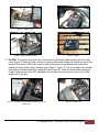
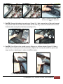
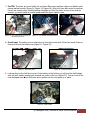
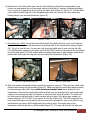
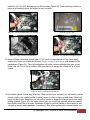
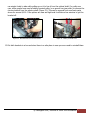
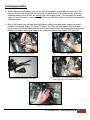
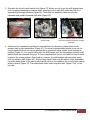
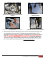
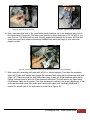
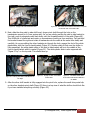
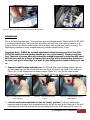
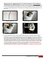
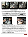
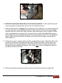
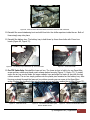
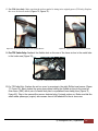
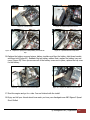
MK5 & MK6 Sigma 5 Speed Shifter Install These instructions might seem lengthy but they are thorough and most people appreciate that. This install should take about an hour to perform. Also, these instructions ONLY apply to the dieselgeek.com Sigma Shifter that went on sale on September 28th, 2009. These instructions will not work on any other shifter in existence and are COPYWRITED material and pictures! Tools Needed 3/8 drive ratchet 10mm and 13mm (1/2 inch will usually work) socket in 3/8 drive size 5mm Allen wrench or socket Channel lock pliers or special hose clamp pliers for MAF clamp (TDI) 3/8 box end wrench (10mm will work) All-purpose lubricant such as WD-40 or equivalent Removal of Stock Shift Mechanism 1. Always work on a cool car. These engines get hot! You will burn yourself otherwise. 2. Park car on level ground, set hand brake. Daylight really works best for seeing what you are doing. Pull hood latch and open hood. 3. For TDI: You must to remove the battery tray, battery and air box to do this install. First remove the battery cover if present and then loosen both of the battery cable clamps (Figure 1, Figure 2). Next, remove the battery hold down bolt and battery (Figure 3, Figure 4). All cars with the 2.5 liter 5 cylinder gas engine do not require air box removal but they do require removal of the battery and battery support tray so skip to Step 8. © Dieselgeek.com | Tools Needed 1 Figure 1 - Battery Cover Figure 2 - Battery Cable Clamps Figure 3 - Battery Hold Down Bolt Figure 4 - Battery 4. For TDI: To remove the air box cover, unscrew the eight Phillips head screws from the air box cover.(Figure 5, Figure 6). Next, remove the spring hose clamp holding the flexible air pipe to the mass air flow sensor (MAF) with a pair of channel lock pliers or specialized hose clamp pliers. Unplug the mass airflow sensor electrical plug (Figure 7, Figure 8). There is a catch in the middle that must be pressed upwards to release the plug (Figure 9). Leave the small rubber passenger (engine) side vacuum hose (TDI) attached to the air box cover and set the cover on top of the engine out of the way. Figure 5 - Unscrew the Eight Phillips Head Screws from the Air Box Cover Figure 6 - Air Box Cover © Dieselgeek.com | Removal of Stock Shift Mechanism 2 Figure 7 - Holding The Flexible Air Pipe Figure 8 - Specialized Hose Clamp Pliers Figure 9 - The Catch in the Middle That Must Be Pressed Upwards to Release the Plug 5. For TDI: Remove the battery tray end cover (Figure 10). Next, remove the air filter and louvered tray that sits under the air filter and set aside. On the TDI only, remove the flexible duct from the aluminum tube coming from the turbo area (Figure 11). Figure 10 - Battery Tray End Cover Figure 11 - Flexible Duct 6. For TDI: Pop off the air box snorkel cover by lifting up on all three catches (Figure 12).Make a mental note on which groove the snorkel sits in (Figure 13). You may also mark the groove with magic marker or liquid paper to make reinstallation easier. Figure 12 - Lifting Up On All Three Catches Figure 13 - Groove the Snorkel Sits in © Dieselgeek.com | Removal of Stock Shift Mechanism 3 7. For TDI: The lower air box is held in by one 5mm Allen screw and two rubber and plastic quickrelease barbed mounts (Figure 14, Figure 15, Figure 16). After the 5mm Allen screw is removed the air box comes out by carefully pulling it straight up. After the lower air box is free from its mounts, you must snake its snorkel underneath the upper radiator hose. Figure 14 - The Lower Air Box Is Held in by One 5mm Allen Screw Figure 15 - Two Rubber And Plastic Mounts Figure 16 - Mounts 8. For all cars: The battery tray is held down by three 6mm bolts with 10mm hex heads. Remove them and lift out the battery tray (Figure 17, Figure 18). Figure 17 - Three 6mm bolts Figure 18 - 10mm Hex Heads 9. Looking down to the left hand corner of the battery at the bottom you will see the shift linkage with two shift cables running back towards the center of the car (Figure 19). You can look at the new dieselgeek.com short shift parts and visualize how the new parts go in place. Figure 19 - Shift Linkage © Dieselgeek.com | Removal of Stock Shift Mechanism 4 10. Detach both of the shift cable ends from the shift cables by pulling their knurled plastic rings toward you and against the coil spring and turning it clockwise (or counter-clockwise depending how you look at it) against its stop to unlock the cable ends (Figure 20, Figure 21). This will allow you to slide the cable ends off of the threaded cables after you remove the shiny metal clips holding them to the stock shift brackets (Figure 22). Figure 20 - Knurled Plastic Rings 11. Figure 21 - Unlock Figure 22 - Shiny Metal Clips All models up to 2008: On the left-most shift bracket (the small, dull silver one), undo the shiny metal clip with your fingernail that secures its pivoting shaft to the transmission housing (Figure 23). Try not to lose this clip. You can use a clip from your cable ends in case you lose the clip. (The VW/Audi part number for the shiny clip is N 908 159 03 and it is the same as the clip holding the stock cable ends.) On 2008 models which use black plastic side to side brackets, unhook the plastic catch that keeps the long pivot pin secured to the transmission (Figure 24). Figure 23 - Undo the Shiny Metal Clip Figure 24 - Plastic Catch 12. Slide this smaller sheetmetal bracket towards the engine to remove it. There are two round white plastic pivot bushings on this bracket (Figure 25). Make sure that the round white plastic bushing on the passenger side (LHD) stays in the aluminum bracket/tube that is attached to the transmission. Remove the round white plastic bushing from the stock flat silver shift bracket and replace it in the aluminum tube if it happens to come out with the shift bracket. The shifter will not work properly without both of these bushings being in place! The factory part number for these bushings is 1J0 711 067L if you happen to lose one (Figure 26). The 2008 models will not have these bushings from the factory but new ones will be provided for you in the shift kit if you specified that you have a 2008 model during the order process. The empty tube on the transmission will look like this on 2008 models (Figure 27). The tube will look like this after you © Dieselgeek.com | Removal of Stock Shift Mechanism 5 install the 1J0 711 067L bushings on the 2008 models (Figure 28). These bushings must be in place on all models to allow the shifter to work correctly. Figure 25 - Two Round White Plastic Pivot Bushings Figure 26 - 1J0 711 067L Figure 27 - Empty Tube On the Transmission Figure 28 - The Tube After the Bushings Install 13. Using a 13mm socket and ratchet (plus 12"-18" worth of extension bars if you have them), remove the 13mm nut holding the chrome Klingon warship-shaped chrome shift bracket to the transmission (Figure 29). The shift mechanism will rotate counter-clockwise into gear as you loosen this nut. This is not a problem. After you remove it, discard the 13mm nut as it is not reused. Figure 29 - Using a 13mm Socket and Ratchet 14. Use leather gloves for this step! After the 13mm nut has been removed, you will need to put the selector shaft in the middle position (neutral) where it is free to move up and down. Place both hands on the chrome bracket so you can pull up evenly or wiggle the bracket side to side while pulling upwards (Figure 30). Use some control since you might hurt yourself when the bracket does finally come free of its shaft. Sometimes it helps to get both hands on this bracket so you can pull up evenly (and repeatedly, if necessary). Also, while grabbing the chrome bracket, you © Dieselgeek.com | Removal of Stock Shift Mechanism 6 can wiggle it side to side while pulling up on it to free it from the splined shaft. For really new cars, some people have used a battery terminal puller (or a generic two jaw puller) to remove the chrome bracket from the selector shaft (Figure 31). This can be sourced from most auto parts stores for around $4.00. If the splines are new and tight and it will take a few minutes to get the bracket off. Figure 30 - Both Hands On the Chrome Bracket Figure 31 - Battery Terminal Puller 15. Put both brackets in a box and store them in a safe place in case you ever need to reinstall them. © Dieselgeek.com | Removal of Stock Shift Mechanism 7 Install Sigma Shifter 1. While holding the shift parts in your hands, use the supplied L-shaped Allen wrench and a 3/8 inch box end wrench (10mm will work usually) to tighten all ten of the Allen screws of the two aluminum cable ends until they are almost snug (very slightly loose). This will make the install easier. Be careful though, if you over tighten them you will not be able to insert the threaded shift cables into them. 2. Back in the engine bay; pull back both shift cables rubber boots and plastic rings to expose all threads of the cables (Figure 32, Figure 33, Figure 34). After the clear plastic rings have been broken loose, slide them toward the rear of the car to expose all of the threads and smooth cable. Reattach the black rubber cable boots to the clear plastic cable rings (Figure 35, Figure 36). Figure 32 - Shift Cables Rubber Boots Figure 33 - Plastic Rings Figure 34 - Expose All Threads of the Cables Figure 35 - After the Clear Plastic Rings Have Been Broken Loose, Slide Them Toward the Rear of the Car Figure 36 - Smooth Cable © Dieselgeek.com | Install Sigma Shifter 8 3. Start with the front to back bracket first (Figure 37). Before you try to put the shift bracket back onto the splined transmission selector shaft, spray the front to back shift cable with WD-40 or equivalent light weight lubricant (Figure 38). Then slide the aluminum cable end onto the lubricated and partially threaded shift cable (Figure 39). Figure 37 - Front to Back Bracket Figure 38 - Splined Transmission Selector Shaft Figure 39 - Slide the Aluminum Cable End Onto the Lubricated and Partially Threaded Shift Cable 4. At this point it is extremely important to note that there is a keyway or joined spline on the selector shaft on the transmission (Figure 40). The correct corresponding keyway to use on the front to back shift lever is a keyway marked with a permanent magic marker mark denoting its position (Figure 41). You cannot easily push the shift bracket onto the transmission selector shaft without these two elements lining up. It is very important that you do not install the front to back bracket in the wrong position. Once lined up, however, the shift bracket will push pretty easily onto the selector shaft (Figure 42). Another easy check is that once the shifter is fully assembled, the white plastic slider of the side to side bracket will be in the middle of the front to back bracket while in neutral (Figure 43). The white plastic slider is also engraved with "Sigma 5 Top" on the top side. © Dieselgeek.com | Install Sigma Shifter 9 Figure 40 - Keyway or Joined Spline On the Selector Shaft On the Transmission Figure 41 - Keyway Marked with a Permanent Magic Marker Mark Denoting Its Position Figure 42 - Once Lined Up, the Shift Bracket Will Push Pretty Easily Onto the Selector Shaft Figure 43 - White Plastic Slider of the Side to Side Bracket in the Middle of the Front to Back Bracket (in Neutral) 5. Next, thread the supplied new OE 13mm lock nut by hand onto the shaft and then tighten it with your ratchet but do not go crazy with it (The Bentley service manual says tighten to 18 foot pounds but this accuracy is hard to achieve since the extensions alter the torque wrench reading) (Figure 44). You absolutely must not reuse the old locknut that you removed from the stock shifter. The Sigma shifter will not work with the original lock nut. While you are tightening the new locknut, the selector shaft will rotate clockwise before the nut gets tight (Figure 45). After the nut has been tightened, rotate the shift bracket counter-clockwise to the neutral position. In the neutral position the front to back shift bracket can be moved up and down. © Dieselgeek.com | Install Sigma Shifter 10 Figure 44 - New OE 13mm Lock Nut Figure 45 - Tightening the New Locknut 6. Next, make sure that both of the round white plastic bushings are in the aluminum pivot hole in the transmission (Figure 46). The factory part number for these bushings is 1J0 711 067L if you have lost one. The shifter will not work correctly unless both bushings are in place. All 2008 and newer cars must have brand new bushings installed here which we supply if your order was placed correctly. Figure 46 - Round White Plastic Bushings in the Aluminum Pivot Hole in the Transmission 7. Next, spray the remaining shift cable with WD-40 or similar lubricant. Then take the remaining silver side to side shift bracket and engage the lubricated shift cable with the aluminum cable end (Figure 47). Make sure that the shift cable slides freely in and out of the aluminum cable end by cycling it several times in and out of the aluminum cable end (This will remove any burrs inside the aluminum cable end if present.) This free movement is crucial to the proper adjustment of the shifter as described below. Also make sure that the shift cable boot has been pulled back to expose the smooth part of the shift cable as shown here (Figure 48). © Dieselgeek.com | Install Sigma Shifter 11 Figure 47 - Engage The Lubricated Shift Cable Figure 48 - Shift Cable Boot Has Been Pulled Back to Expose the Smooth Part of the Shift Cable 8. Next, slide the silver side to side shift lever's longer pivot shaft through the hole on the transmission meant for it (from engine side). As you are slowly pushing the side to side bracket to the right, push its aluminum cable end slowly onto the threaded section of the cable (Figure 49). This is little bit of a ballet act and under no circumstance should you force anything. You just feed the bracket toward the right and rotate it backwards onto the cable at the same time slowly and carefully. As you are sliding the silver brackets pin through the hole, engage the slot of the white plastic slider with the front to back bracket (Figure 50). Another check is that once the shifter is fully assembled, the white plastic slider of the side to side bracket will be in the middle of the front to back bracket while in neutral (Figure 51). The white plastic slider is also engraved with "Sigma 5 Top" on the top side. This should face up. Figure 49 - Pushing The Side To Side Bracket To The Right Figure 50 - Engage the Slot of the White Plastic Slider Figure 51 - The White Plastic Slider of the Side to Side Bracket Will Be in the Middle 9. After the silver shift bracket is fully engaged into the pivot hole, replace the small shiny metal clip on the silver brackets pivot shaft (Figure 52).Here is a top view of what the shifter should look like if you have installed everything correctly (Figure 53). © Dieselgeek.com | Install Sigma Shifter 12 Figure 52 - Small Shiny Metal Clip On the Silver Brackets Pivot Shaft Figure 53 - Top View Adjustment This is the most important part. This procedure must be followed exactly! Please call (210) 852-4819 if you have problems here. Make note that all shifters will feel better when given a week or so to break in as there are friction surfaces that will be polished with several days’ worth of driving. The adjustment procedure is pretty straightforward so problems should be few, if any. Important Note: PLEASE do not seek adjustment advice from anyone other than JIM ROYSTON (which includes posting anything to any online forums!). Please consult me first. That said, of course when you reduce the available leverage by installing ANY short shift kit there with be a degree of higher effort and this will be perceived as notchiness by some. Just give it a few days to a week for the sliding parts to break in before you call us. 1. Expose the shift linkage inside the car. On Golf and Jetta, while working inside of the car, put both hands into the rear of the shift boot and lift up the rear of the frame of the shift boot (Figure 54). It will unsnap from the center console (Figure 55). Then lift the rubber sound deadening boot from the shifter aperture (Figure 56). Lift up the shift boot but don't remove it. Figure 54 - Put Both Hands into the Rear of the Shift Boot Figure 55 - Unsnap from the Center Console Figure 56 - Deadening Boot From The Shifter Aperture 2. Lock the mechanism inside the car into its "Home" position. Do this by inserting the expensive and rare special tool we supplied with the kit into the hole at the lower left of the shift lever and push it through and into the corresponding hole in the shifter base until it bottoms out © Dieselgeek.com | Adjustment 13 (Figure 57, Figure 58, Figure 59, Figure 60). This will give the appearance that the shifter is in second gear which is exactly correct. Also, the shift lever inside the car WILL NOT MOVE if you have successfully put the nail through both holes. If you do not have the nail tool we provide with our kits, the special tool was made from a 4 inch long, 20d Bright Common nail with a 5 mm or .195 inch shank diameter and a 30 degree bend 2.5 inches from the tip of the nail to clear the shift knob. Figure 57 - Special Tool Figure 58 - Lower Left of the Shift Lever Figure 59 - Corresponding Hole Figure 60 - Push Through to Corresponding Hole in the Base 3. Lock the transmission into its "Home" position. Right now, your transmissions black L-shaped locking lever is in the normal operating position and should point to the rear of the car (Figure 61). In the engine bay, make sure that the transmission is in neutral (in neutral the front to back shift bracket is free to move up and down). With your right thumb, push down on the front to back shift bracket approximately 1/3 of an inch and then with your forefinger turn the small black L-shaped locking lever on the transmissions shift tower clockwise while pushing it in (Figure 62). The tip of this black locking lever will end up pointing straight up when the shift mechanism is successfully placed in the locked or home position (Figure 63). You will also not be able to move the front to back shift bracket up and down if the transmission is locked into the home position. © Dieselgeek.com | Adjustment 14 Figure 61 - Black L-Shaped Locking Lever Figure 62 - Turn the Small Black L-Shaped Locking Lever On the Transmissions Shift Tower Clockwise While Pushing It in Figure 63 - The Tip of this Black Locking Lever Will End Up Pointing Straight Up 4. Once you have installed the adjustment nail through both holes inside the car (Step 2) and locked the transmission into its Home position (Step 3) you are ready to tighten the Allen screws that clamp both of the aluminum cable ends to the shift cables. This IS the adjustment for the short shift kit! Where you clamp the cables has everything to do with the proper adjustment of the shifter. If you did not follow all of the preceding steps exactly then do not tighten the Allen screws until you do. If you have followed the directions, tighten the middle Allen screw on the cable ends with the supplied L-shaped Allen wrench and a box end 10mm or 3/8 wrench to hold the lock nuts (Figure 64, Figure 65). Figure 64 - Tighten the Middle Allen Screw On the Cable Ends Figure 65 - The Supplied L-Shaped Allen Wrench 5. Unlock the transmission from its Home position. While pushing down slightly on the front to back bracket, pull the transmission L-shaped locking pin to the left and rotate it counterclockwise until it comes back out to its rest position stop. It will move toward the right side (engine side) of the car by approximately 1/2 inch. (You are not removing the pin completely.) It is very important that you pull this pin back to the normal 10:00 O’clock rest position since your shifter will not work with the pin pushed into the transmission Home position (Figure 66)! Furthermore, you will permanently damage the pin if you forcefully try to shift the mechanism with the pin pushed in! Please do not forget to release the pin after adjustment. The mechanism will still function if you damage the plastic pin but you will have to replace the pin for any future adjustments. The part number for the locking pin is 02J 301 358C and is available at your dealer for about $5.00. It is a pain to install, however. © Dieselgeek.com | Adjustment 15 Figure 66 – The Normal 10:00 O’clock Rest Position 6. Unlock the mechanism inside the car from its Home position. Go back inside the car and remove completely the special bent nail tool from the shifter mechanism. 7. Check the shifter action by gently cycling through the gears (remember, you only have tightened one of the five Allen screws clamping the cables). Make sure that first and second gear engage smoothly without too much effort. Also, make sure that reverse gear is easy to engage. If either first or second gears are not where they are supposed to be, loosen the middle Allen screws of both brackets and do the adjustment procedure over again starting at step #2 in this adjustment section. (Make note that the shifter will always work its best with the engine running and the clutch pushed in.) 8. If all gears are easy to engage, tighten all of the remaining Allen screws. Tighten the Allen screws until the slit in the side of the aluminum cable end will barely allow either a credit card or two playing cards to fit in the gap (Figure 67). Once the ten Allen screws are tight, the shift levers have been properly installed and adjusted. They should never need to be readjusted unless the procedure was done incorrectly. Figure 67 - Two Playing Cards 9. Slide the shift cable boots back toward the aluminum shift cable ends like this (Figure 68). © Dieselgeek.com | Adjustment 16 Figure 68 - Slide the Shift Cable Boots Back Toward the Aluminum Shift Cable Ends 10. Reinstall the sound deadening boot and shift boot into the shifter aperture inside the car. Both of them simply snap into place. 11. Reinstall the battery tray. The battery tray is held down by three 6mm bolts with 10mm hex heads (Figure 69, Figure 70). Figure 69 - The Battery Tray Is Held Down by Three 6mm Bolts Figure 70 – 10mm Hex Heads 12. For TDI Jetta Only: Reinstall the lower air box. The lower air box is held in by one 5mm Allen screw and two rubber and plastic quick-release barbed mounts (Figure 71, Figure 72). To install, snake the air box snorkel under the upper radiator hose and align the lower air box with the two rubber mounts. The air box simply pushes onto the plastic pins mounted on the battery tray. After the pins protrude through the lower air box rubber mounts you can screw in the 5mm Allen screw. Replace the louvered plate into the lower air box and then replace the air filter (Figure 73). Figure 71 - 5mm Allen Screw Figure 72 - Two Rubber and Plastic QuickRelease Barbed Mounts Figure 73 - Screw in the 5mm Allen Screw © Dieselgeek.com | Adjustment 17 13. For TDI Jetta Only: Make sure that the air box snorkel is sitting in its original groove (TDI only). Replace the cover for this air snorkel (Figure 74, Figure 75). Figure 74 - Air Box Snorkel Is Sitting in Its Original Groove Figure 75 - Replace the Cover for this Air Snorkel 14. For TDI Jetta Only: Reattach the flexible duct on the rear of the lower air box to the metal tube in the turbo area (Figure 76). Figure 76 - Reattach the Flexible Duct 15. For TDI Jetta Only: Replace the air box cover by screwing in the eight Phillips head screws (Figure 77, Figure 78). Next, replace the spring hose clamp holding the flexible air pipe to the mass air flow sensor (MAF) with a pair of channel lock pliers or specialized hose clamp pliers (Figure 79, Figure 80). Plug in the mass airflow sensor electrical plug. It simply pushes on. Make sure that the small rubber passenger (engine) side vacuum hose is still attached to the air box cover. © Dieselgeek.com | Adjustment 18 Figure 77 - Air Box Cover Figure 78 - Eight Phillips Head Screws Figure 79 - Replace the Spring Hose Clamp Holding the Flexible Air Pipe Figure 80 - Specialized Hose Clamp Pliers 16. Replace the battery surround pieces, battery insulator and then the battery hold down bracket and 8mm bolt (Figure 81). Reattach the two battery cables. Next, replace the battery tray end cover (Figure 82). Once you are sure all of the battery covers are in place, replace the top cover for the battery. Figure 81 - Hold Down Bracket and 8mm Bolt Figure 82 - Replace the Battery Tray End Cover 17. Start the engine and go for a ride. You are finished with the install. 18. Enjoy and tell your friends about how much you love your dieselgeek.com MK5 Sigma 5 Speed Short Shifter! © Dieselgeek.com | Adjustment 19 Hey, If you see anything in this install manual that is unclear or if you could make anything easier to understand I am all ears. Please email me at [email protected] with suggestions or edits that would improve these instructions. Sometimes when you have done an operation a bunch of times you lose sight of how it must be to be doing it for the first time and having input from first timers would be great. Also letting me know what you think of the Sigma shifter itself would be super groovy... Thanks, Jim Last revision 9-28-09 © Dieselgeek.com | Adjustment 20