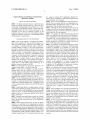
1
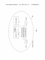
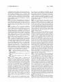
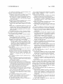
US 20080002686Al
(19) United States
(12) Patent Application Publication (10) Pub. No.: US 2008/0002686 A1
(43) Pub. Date:
Valli et al.
(54)
MAINTAINING AN EXISTING CONNECTION
(57)
Jan. 3, 2008
ABSTRACT
BETWEEN NODES
The present invention refers to a method performed in and
(75) Inventors:
Jyrki Valli, Tampere (Fl); Seppo
Pohja, Tampere (Fl)
corresponding nodes constituting a system which is con?g
ured to maintain an existing connection between a ?rst node
(A) and a second node (B) communicating with each other
Correspondence Address:
via a connection within a communication network. Data is
SQUIRE, SANDERS & DEMPSEY L.L.P.
14TH FLOOR, 8000 TOWERS CRESCENT
TYSONS CORNER, VA 22182
(73) Assignee:
Nokia Corporation
(21) Appl. No.:
11/642,638
(22) Filed:
Dec. 21, 2006
(30)
communicated between the nodes (A, B) via the connection
on the basis of addresses assigned to the respective nodes.
The addresses are managed by an address management node
(Addr_Serv) of the communication network. The system
comprises a detector unit (A2), at the ?rst node (A), con
?gured to detect an outage of the existing connection
Foreign Application Priority Data
between the nodes (A, B), a consulting unit (A3), at said ?rst
node (A), con?gured to consult after detecting the outage of
the connection, the address management node (Addr_Serv)
of the communication network to verify the address assigned
to the second node (B), a transceiver unit(ASl), at said
Jun. 30, 2006
(EP) .............................. .. 06 116 432.3
Publication Classi?cation
(51)
Int. Cl.
H04L 12/56
(52)
US. Cl. ..................................................... .. 370/389
(2006.01)
address management node (Addr_Serv), con?gured to return
a current address assigned to the second node (B) responsive
to a request from the consulting unit to the ?rst node, and a
connection re-establisher unit (A5), at said ?rst node (A),
con?gured to re-establish the connection based on the cur
rent address assigned to the second node (B).
to I from
Node (A)
NW, nodes
A2
<————>
detector
unit
i
.
.
consulting unlt
timer
/
A3
trans
ceiver
A4
previous addr
monitoring
Addr-B
unit
i
request addr
i
A5
receive addr
Addr_B*
connection (re-)establisher unit
@ A6
re-established
connection
A1
Patent Application Publication
Jan. 3, 2008 Sheet 1 0f 5
Q
C
E
H
I
J
m
zmqug
56:.32965% 6coz3w>2cmov_
US 2008/0002686 Al
.5
F
Patent Application Publication
Jan. 3, 2008 Sheet 4 0f 5
US 2008/0002686 A1
Fm
.mcg 628
M
LCOSQ omSo QZOSMDU
mm
V
mm
cEozn5hoa
Q262
c@owEmco: im|au<
B2“$65:2 w99m5Ez9u2mc: zaw dgq
.mm
w
Patent Application Publication
Jan. 3, 2008 Sheet 5 0f 5
‘iv
wum>2cgoumw 26Ew3u5?n0m: E2350 $2 6
Nm<
wmAEin2oduc<xméE EmoScmE
:wE2u5c0m
US 2008/0002686 A1
Jan. 3, 2008
US 2008/0002686 A1
MAINTAINING AN EXISTING CONNECTION
BETWEEN NODES
FIELD OF THE INVENTION
[0001] The present invention relates to a method of main
taining an existing connection betWeen a ?rst node and a
second node communicating With each other via a connec
tion Within a communication network, Wherein data com
municated betWeen the nodes via the connection are com
municated on the basis of addresses assigned to the
respective nodes, and at least one of the addresses changes
during the connection, as Well as to a corresponding system
and the respective nodes thereof.
BACKGROUND OF THE INVENTION
[0002]
With recent progress in communication technol
etc., using for example ASIC (Application Speci?c Inte
grated Circuit) components or DSP (Digital Signal Proces
sor) components, as an example;
[0009] devices can be implemented as individual devices,
but this does not exclude that they are implemented in a
distributed fashion throughout the system, as long as the
functionality of the device/system is preserved.
[0010] Although the present description Will be given on
a general level as the invention is applicable to any com
munication netWork, it is pointed out that the invention is
most suitable for IP based netWorks.
[0011]
For example, tWo nodes communicating With each
other on an application level are having a so-called peer-to
peer communication. The application level is carried on a
connection level. A level as mentioned here corresponds to
a layer in a layered communication model. HoWever, the
present invention is not limited to a speci?c OSI layer or
ogy, various scenarios Will arise in Which an address of a
layers. (OSIIOpen System Interconnection).
node may change during a connection With another node.
[0012] Nevertheless, a communication betWeen tWo nodes
as described in examples of scenarios to Which the present
invention is applicable, is not limited to a peer-to-peer
For example, a connection betWeen nodes is broken or
generally exhibits an outage, eg due to fast moving termi
nal nodes in mobile netWorks, or the like. Nodes such as
communication. Rather, IETF (Internet Engineering Task
terminals of end users or even servers acting as a node With
Force) de?nes a client as a host (node) that initiates e.g. IP
Which a terminal is communicating Will, hoWever, experi
ence such outage (e.g. caused by a break/failure) in the
communication by sending the ?rst packet to another node
connection as rather inconvenient. A temporary connection
incoming packets from a client. In such a frameWork, tWo
outage need not necessarily be caused by a connection
failure Which is usually related to eg a failure on the
peers are nothing but tWo hosts that can assume the role of
either a client or a server (or both). (Other de?nitions of
physical layer, though this is not excluded here. Rather, a
peer-to-peer exist, too, in abundance.) Nonetheless, the
connection outage as discussed in the present invention is
mostly due to a node address change caused eg by a
physical connection change or the like.
[0003] For the purpose of the present invention to be
described herein beloW, it should be noted that
[0004] a node may for example be any kind of commu
invention is also applicable to a variety of client-server
scenarios. Its applicability to peer-to-peer scenarios is a
nication device, such as a Wireless or Wired device, eg
and a server as a host thatiWhen idleiWaits and listens to
by-product of its applicability to client-server scenarios
under the above-given de?nition of peer-to-peer.
[0013] For example, a peer-to-peer communication appli
cation betWeen tWo nodes A and B may reside in a scenario
as folloWs. Anode (client) negotiates and establishes an IPv6
personal computer, mobile phone or the like, irrespective of
tunnel over an IPv4 connection to a tunnelling server. The
a speci?c standard to Which these conform as long as they
are compatible to a communication netWork; a node may be
tunnelling server and the intermediate IPv6 netWork then
route IPv6 traf?c to and from another node. The IPv4
connection may break or be subject to an outage uninten
tionally eg because of a node (eg a mobile phone) Will
a terminal (also referred to as client) or a server;
[0005] for the communication netWork any suitable pro
tocol for operating/message exchange is possible; only as an
example it is noted that packet based communication net
Works such as IP based netWorks (e.g. conforming to IPv4
or IPv6) are particularly suitable to be used With the present
move from one BTS area to another experiencing a change
of the node’s IP address of the IPv4 connection. The node
may also change intentionally the IPv4 connectivity eg
method steps likely to be implemented as softWare
from GPRS to WLAN, if WLAN becomes available, Which
could also lead to a change of the IPv4 connection node
address.
code portions and being run using a processor at one of the
nodes, are softWare code independent and can be speci?ed
outage, the same applies as Well to the IPv6 tunnel and
using any knoWn or future developed programming lan
guage as long as the functionality de?ned by the method
have been established betWeen this node and other nodes.
invention;
[0006]
[0014]
If the underlying IPv4 connectivity experiences an
possible peer-to-peer connections (With applications) that
steps is preserved;
[0015]
[0007]
connections, and requiring from the user manual re-estab
lishment of the connection.
generally, any method step is suitable to be imple
mented as softWare or by hardWare Without changing the
idea of the present invention in terms of the functionality
implemented;
[0008]
method steps and/or devices or parts of devices
This results in applications losing the peer-to-peer
[0016] In case of eg group VOIP (Voice over IP) com
munication as an application example, With members of the
VOIP group moving around in a metropolitan area, the
referred to as units likely to be implemented as hardWare
components at one of the server/terminal entities are hard
usability of the application Would be ruined if in practice
Ware independent and can be implemented using any knoWn
or future developed hardWare technology or any hybrids of
these, such as MOS (Metal Oxide Semiconductor), CMOS
Would ?rst have to manually check With Whom you have lost
the connection, and re-establish the connections manually.
OtherWise the peers/nodes that have dropped the (peer-to
(Complementary MOS), BiCMOS (Bipolar CMOS), ECL
(Emitter Coupled Logic), TTL (Transistor Transistor Logic),
peer) connection With your node Will not receive the VOIP
message.
every time you Want to communicate With the group you
Jan. 3, 2008
US 2008/0002686 A1
[0017]
To summarize, there are situations emerging Which
lead to the problem of hoW a node can maintain IP
connectivity or generally an ongoing communication con
nection With another node, Whose IP-address changes, With
out terminating the application(s) running betWeen the nodes
on top of it, ie on top of the IP connectivity layer. This is
especially critical for any type of real time applications,
[0026] According to aspects of the present invention, this
object is for example achieved by a method, system and
nodes as de?ned in the respective independent claims
Advantageous further developments of those aspects of the
present invention are for example de?ned in respective
Where the tolerable connection interruption time on the
dependent claims.
[0027] In detail, according to particular aspects of the
present invention and respective sub-aspects thereof, there is
application layer is quite short. HoWever, the applicability of
disclosed a method of maintaining a connection betWeen a
the present invention as described hereinafter is not limited
?rst node and a second node, comprising: detecting, by the
to real time applications. Rather, real time applications are
merely referred to as an example for applications Which fail
?rst node, an outage of an existing connection betWeen the
?rst and second nodes; consulting, by said ?rst node, after
in cases or require specialiZed code to cope With situations
in Which the address of a communication partner node
ment node of a communication netWork to verify an address
changes. Generally, it is to be noted that the present inven
tion is advantageously applicable to applications Which fail
management node, a current address assigned to the second
in cases or require specialiZed code to cope With situations
in Which the address of a communication partner node
changes. Real-time applications are only referred to as a
descriptive example Without limiting the scope of applica
bility of the present invention.
[0018] Irrespective of the above examples focusing on
peer-to-peer scenarios, it has to be kept in mind that
examples of client-server scenario also exist. The invention
is also not limited to cases Where tunnelling is used.
[0019]
Generally, the folloWing example cases are appli
cable, Where one of the nodes has a public address to Which
traf?c from another node can be routed (i.e. the node is
addressable and reachable), and the address changes during
an ongoing transmission betWeen the nodes.
detecting the outage of the connection, an address manage
assigned to the second node; returning, from said address
node; and re-establishing the existing connection, by said
?rst node, based on the current address assigned to the
second node; Wherein data is communicated betWeen the
?rst and second nodes on the basis of addresses assigned to
the respective nodes, and Wherein the addresses are managed
by the address management node of the communication
netWork;
[0028] said detecting comprises receiving an error mes
sage that the connection to the second node is interrupted;
[0029]
said detecting comprises experiencing a timeout
When Waiting for a response or acknoWledgement from the
second node;
[0030] the method further comprises assigning, to the
second node, a current address, Wherein the assigned address
[0020] The public address is assigned to the node by
eg a DHCP (Dynamic Host Con?guration Protocol)
is associated With a life-time attribute, for the current
server for a lease period. Upon lease expiration, the
entries in other nodes than the address management node,
node gets a different address from the DHCP server.
the lifetime attribute being set to Zero or about 0;
[0021]
The public address is assigned to the node by
eg a NAT (Network Address Translation) or NAPT
(Network Address Port Translation) server, Which sud
denly assigns a different address to the node.
[0022]
The public address is assigned to the node by
eg a tunnelling server, Which suddenly assigns a
different address to the node.
[0023] Thus, problems as those mentioned in the above
examples may occur on any netWork, Where the node
address may change Without a Warning, e.g., on the Internet
if the server uses dynamic DNS and its address changes, say,
under DHCP.
[0024] Furthermore, in connection With IP based net
Works, Dynamic Domain Name Service (DynDNS) is
Widely knoW in the Internet and has been into use there for
a long time. Nevertheless, DynDNS has not been used as a
mechanism to recover from node address changes for real
time tra?ic in a fast enough manner, to prevent terminating
of eg the real time application running on top of the
connection. Recovery from IP address changes for a stan
dard DynDNS implementation is sloW and takes some time
(in the area of minutes, for example the minimum time-to
live time for caching of DNS entries is de?ned to 60 s).
SUMMARY
[0025]
Hence, the present invention addresses the above
address, for caching address_to_node_name mapping
[0031] said consulting comprises monitoring a time inter
val, by said ?rst node, responsive to the detection of the
outage; realiZing, by said ?rst node, that the time interval
expired; requesting, by the ?rst node, the current address of
the second node from the address management node respon
sive to realiZing that the time interval has expired;
[0032]
said consulting comprises trying to re-establish the
connection to the second node by using an earlier knoWn
address of the second node until the time interval expires;
[0033] the timer is stopped and the process of re-estab
lishing the connection ends, When the connection to node B
could be re-established by using the earlier knoWn address
of the second node before the time interval expires;
[0034] data communicated betWeen the nodes via the
connection are data relating to an application carried on a
layer above a layer of the connection, and a time interval
monitored has a length that is shorter than a time required for
the application to indicate a failure or terminate;
[0035] the outage of the connection is based on a change
of logical or physical channels of the connection;
[0036] the connection changes from one type of connec
tion to another type of connection.
[0037] Also, there is disclosed a computer program prod
uct comprising computer implementable instructions for
carrying out the method according to any of the above
aspects and sub-aspects When executed on a processor.
mentioned problem to maintain an ongoing communication
connection With another node, Whose address changes, With
minimal loss of performance and With minimal disturbance
maintain an existing connection betWeen a ?rst node and a
for an application carried on top of such a connection.
con?gured to detect an outage of an existing connection
[0038]
Further, there is disclosed a system con?gured to
second node, comprising: a detector unit, at the ?rst node,
Jan. 3, 2008
US 2008/0002686 A1
between the ?rst and second nodes; a consulting unit, at said
?rst node, con?gured to consult after detecting the outage of
the connection, an address management node of a commu
nication network to verify an address assigned to the second
node; a transceiver unit, at said address management node,
con?gured to return a current address assigned to the second
node responsive to a request from the consulting unit to the
?rst node; and a connection re-establisher unit, at said ?rst
node, con?gured to re-establish the connection based on a
current address assigned to the second node, wherein data is
communicated between the ?rst and second nodes on the
basis of addresses assigned to the respective nodes, and
wherein the addresses are managed by the address manage
ment node of the communication network;
[0039] said detector unit comprises a receiving unit con
[0050] said detector unit comprises a receiving unit con
?gured to receive an error message informing the ?rst node
that a message addressed from the ?rst node to the second
node was not delivered;
[0051] said detector unit comprises a receiving unit con
?gured to experience a timeout when waiting for a response
or acknowledgement from the second node;
[0052]
the consulting unit comprises a monitoring unit
con?gured to monitor a time interval responsive to the
detection of the outage, the monitoring unit being con?gured
to realiZe that the time interval expires, and wherein the
re-establisher unit is con?gured to request a current address
of the second node from the address management node
responsive to realiZing that the time interval has expired;
[0053] said re-establisher unit is con?gured to try to
?gured to receive an error message informing the ?rst node
that a message addressed from the ?rst node to the second
node was not delivered;
re-establish the connection to the second node by using an
earlier known address of the second node B until the time
[0040] said detector unit comprises a receiving unit con
?gured to experience a timeout when waiting for a response
or acknowledgement from the second node,
[0054] the monitoring unit is con?gured to stop the timer
unit and to end the process of re-establishing the connection,
[0041]
the system further comprises an address assignor
node con?gured to assign a current address to the second
node, the assigned address being associated with a life-time
attribute, for the current address, for caching address_to_
node_name mapping entries in other nodes than the address
management node, the lifetime attribute being set to Zero or
about 0;
[0042] the consulting unit comprises a monitoring unit
interval expires;
when the connection to the second node could be re
established by using the earlier known address of the second
node B (ADDR B) before the time interval expires;
[0055] data communicated between the ?rst node and the
second node via a connection comprises data relating to an
application carried on a layer above a layer of the connec
tion, and wherein the time interval monitored has a length
that is shorter than a time required for the application to
indicate a failure or terminate.
con?gured to monitor a time interval responsive to the
[0056]
detection of the outage, the monitoring unit being con?gured
node (Addr_Serv), comprising
to realiZe that the time interval expires, and wherein the
re-establisher unit is con?gured to request the current
address of the second node from the address management
node responsive to realiZing that the time interval has
[0057] a transceiver unit con?gured to return a current
address assigned to a second node responsive to a request
from a consulting unit of a ?rst node;
expired;
management unit con?gured to manage a current address of
the second node by writing the current address into or
fetching the address from a memory unit of the address
[0043] said re-establisher unit is con?gured to try to
re-establish the connection to the second node by using an
earlier known address of the second node until the time
[0058]
Further, there is disclosed an address management
the address management node further comprises a
interval expires;
management node.
[0059] Additionally, there is disclosed an address assignor
[0044] the monitoring unit is con?gured to stop the timer
unit and to end the process of re-establishing the connection,
node,
when the connection to the second node could be re
node, the assigned address being associated with a life-time
attribute, for the current address, for caching address_to_
node_name mapping entries in other nodes than the address
established by using the earlier known address of the second
node before the time interval expires;
[0045] data communicated between the nodes via the
connection are data relating to an application carried on a
layer above a layer of the connection, and the time interval
monitored has a length that is shorter than a time required for
the application to indicate a failure or terminate;
[0046] the outage of the connection is based on a change
[0060]
con?gured to assign a current address to a second
management node, the lifetime attribute being set to Zero or
about 0.
[0061] Thus, stated in other words, if a ?rst node A is
facing a situation where it is about to abandon an application
and/or a connection to a second node B, because eg a
“timeout limit” is reached for the application or the connec
of the logical or physical channels of the connection;
tion (i.e. the sent packets are not reaching node B anymore),
[0047] the connection changes from one type of connec
tion to another type of connection.
[0048] In addition, there is disclosed a node comprising
[0049] a detector unit con?gured to detect an outage of an
existing connection between the ?rst node and a second
node via a communication network; a consulting unit, con
?gured to consult after detecting the outage of the connec
tion, an address management node of a communication
the invention proposes for example that node A makes a
network to verify the address assigned to the second node;
and a connection re-establisher unit con?gured to re-estab
lish the connection based on a current address assigned to
the second node;
query to an address management node such as eg a DNS
query on node B in order to check if the lP-address of node
B has changed, before the application running on top of the
connection or the connection is ?nally terminated. If the ?rst
node A recognises that for example the IP address of the
second node B has changed, Node A starts resending of the
packets to the new lP-address of node B before the appli
cation or the underlying connection is timed out, in order to
maintain the connection.
[0062] Note that the expression “addresses being managed
by an address management node of the communication
Jan. 3, 2008
US 2008/0002686 A1
network” is to a certain extent a simpli?cation for explana
[0075]
tory purposes. The invention relates for example to a (gen
eraliZation of) a scenario Where dynamic DNS is used in the
management node (ADDR_SERV) according to the present
FIG. 5 shoWs a block diagram of an address
invention.
IP World: Each node has an address (:IP-address) and a
name (:hostname e.g. WWW.nokia.com). The communica
tion netWork provides a name-to-address mapping function
DESCRIPTION OF ASPECTS OF THE PRESENT
INVENTION
(:DNS) that a node can use to learn the address of another
node based on the name. The invention is particularly useful
in cases Where the address of the node may occasionally
[0076] The aspects of the present invention Will noW be
described With reference to the accompanying Figures in
change and Where the node consequently updates the
address mapped to its name in the name-to-address function
(Which implies in a speci?c example that the DNS is a
dynamic DNS). For the purposes of this invention, the name
can be assumed unchanging.
[0063] Thus, address management describes the keeping
track of the address assigned to a node of a given name and
the possibility to provide for a looking-up of the node to
address assignment. Assigning of the addresses can be
accomplished separately from the “address management”,
eg by a DHCP server entity, although both functions could
reside in the same netWork node.
[0064]
The invention relates under a particular aspect to
tackling the problem of maintaining (IP-)connectivity With
another node Whose (IP-)address changes due to break-up in
(lP)connectivity. Nevertheless the present invention is not
limited to speci?c types of netWorks and could be used
alWays When the address (eg IP address) of one party
during an ongoing call changes and the (IP) connectivity
shall be maintained. Note, changing of (IP) addresses might
happen for example due to a temporary connection inter
ruption (outage), When changing the connection from eg
GPRS to WLAN, if WLAN becomes available, or When the
lease time for an IP address expires and the node gets a neW
IP address assigned by eg a DHCP server.
[0065] Accordingly, With the present invention, at least the
folloWing advantages can be achieved, Whether individually
or in combination:
[0066]
According to an aspect of the present invention, a
method comparable With DynDNS is suggested, Which is
improved With respect to the performance response time.
[0067] Moreover, the present invention provides IP mobil
ity support for eg real time applications. Applications are
kept alive if the local and/or remote node IP address
changes, even if also a (tunneling) server IP address
changes.
[0068] The method/mechanism and nodes of the system as
described under aspects of this invention can be applied in
more detail. The present invention is applicable to all above
described example scenarios, even though the folloWing
description may focus on only one of these examples or only
on a common aspect thereof.
[0077] FIG. 1 shoWs an overvieW of the system according
to an aspect of the present invention. As shoWn in FIG. 1, the
system comprises a (part of a) netWork NW. The netWork
comprises a ?rst node A and a second node B. The nodes A,
B are identi?ed by respective addresses ADDR_A and
ADDR_B. Data communicated betWeen the nodes A, B are
communicated on the basis of these addresses assigned to
the respective nodes. Addresses are assigned to the respec
tive nodes by an address assignor node “Addr_Assignor”.
Indicated by arroWs is the functionality that the nodes A, B
to Which addresses are assigned are informed about the
assigned addresses. Also, the address assignor node may
inform a further node Within the netWork of the (neW)
address to node name assignment, address management
node “ADDR_SERV” of the communication netWork Which
is also shoWn in FIG. 1 and Which manages the address to
node name assignments so that these can be looked-up.
Note, that there may exist also other Ways hoW to inform the
address management node about (neW) address to-node
name assignments (eg the address management node is
informed by the node itself Which receives the neW address).
The address management node ADDR_SERV has thus
knoWledge of the addresses assigned to the nodes in the
netWorks, receives requests for node address information for
requested node names, and returns the information concem
ing assigned addresses as illustrated by the double arroWs at
the address management node ADDR_SERV. Associated to
or part of the address management node is a memory in
Which the addresses to node names mapping is maintained.
FIG. 1 shoWs that node A is assigned address ADDR_A and
node B is assigned the address ADDR_B. Furthermore, as
shoWn in FIG. 1, an existing connection is established and
ongoing betWeen the ?rst node A and the second node B. In
the illustrated case, it is assumed that as an example a
real-time communication (application) is established via this
any netWork Where mobility shall be supported.
[0069] The invention improves usability of eg a tunnel
prises at least tWo layers. These are the connection layer as
ing netWork scenario as connections are automatically re
the loWer layer and an application layer as a higher layer.
established instead of manual re-establishment.
BRIEF DESCRIPTION OF THE DRAWINGS
[0070]
The aspects of the present invention Will hereinaf
ter be described With reference to the draWings, in Which
[0071] FIG. 1 shoWs an overvieW of the system according
to the present invention;
[0072] FIG. 2 shoWs a signaling diagram of aspects
involved in the present invention;
[0073] FIG. 3 shoWs a block diagram of a node (node A)
according to the present invention;
[0074] FIG. 4 shoWs a block diagram of a node (node B)
according to the present invention; and
connection. The illustrated real-time communication com
The connection layer serves to transport the data on the
physical/logical channels, and the application layer is a
higher layer application in relation to Which payload/use
data are communicated.
[0078]
The present invention is not limited to a particular
communication netWork or netWork system. The nodes can
be Wired nodes or Wireless nodes. The communication is for
example packet based and can be based on the Internet
protocol IP. It is not important Which protocol version is
concerned (IPv4 or IPv6, or any other). In case of an IP
based netWork, messages communicated betWeen the nodes
are IP packets and the address management node is a name
server such as a DNS (Domain Name Service) server, While
the address assignor is eg a DHCP server. In case of a
Jan. 3, 2008
US 2008/0002686 A1
communication network based on IPv6, the messages com
municated are also IP packets based on that protocol version
and the address management server is a dynamic DNS
server. Still further, it is possible that the present invention
is applied in a scenario or architecture involving tunneling.
In such a scenario, the connection layer can be an IPv4 layer
and the application layer can for example be a tunneled
application based on IPv6.
[0079] FIG. 2 shoWs a signaling diagram of signaling and
processing performed in an example scenario at respective
nodes. In the horiZontal direction, the nodes involved are
illustrated Whereas the vertical sequence of processing steps/
signaling messages re?ects the sequence in time in a rough
outline.
[0080]
but could also be accomplished automatically once the
address assignor node is informed by a mechanism different
from a request of the node B. In this regard, as an alternative
example not shoWn in FIG. 2, transparently for the node B,
a certain mechanism accomplishes assignment of a neW
address to node B. Step S5 is thus performed at the address
assignor based on a trigger event differing from the request
in step S4 from node B.
[0088] Just as an example for such an trigger event, the
lifetime of an address assigned to node B may expire (for
example the DHCP lease time) and a neW address is thus
necessary to be assigned to node B. Steps S3 and S4 shoWn
in FIG. 2 then do not occur. Further, in such scenario, the
connection outage experienced in step S2 Would occur rather
As shoWn in FIG. 2, the system constituents
as a result of that address change since data transmitted from
already described above With reference to FIG. 1 are
node A to node B based on the old address ofnode B can no
involved. Other nodes and/ or netWork entities are not shoWn
longer be delivered to node B With the neW address being
merely for the reasons of keeping the explanation and
draWings simple and easy to understand. It is, hoWever, not
assigned thereto. Thus, step S5 takes place prior to step S2
in such a modi?ed scenario.
excluded that depending on the actual netWork concerned to
[0089] To clarify, the previously ongoing e.g. real-time
Which the present invention may be applied, corresponding
communication With node B Was based on node B’s address
further netWork entities are involved in the background
ADDR_B. In step S5, the current (neW) address ADDR_B*
is assigned to node B. Furthermore, optionally, the address
Without in?uencing the aspects of the present invention
described herein in order to contribute to the, in other
aspects, normal “behavior/functioning” of the netWork.
[0081] As shoWn in the example scenario of FIG. 2, node
A has an ongoing, for example real-time, communication
With node B. Node A is assigned address ADDR_A and node
B is assigned address ADDR_B. The real-time communica
tion in the example scenario relies eg on a peer-to-peer
application layer (higher layer) on top of a connection layer
assignor node sets a lifetime attribute for caching of the
address to name mapping of the second node B in other
nodes than the ADDR_SERV to Zero, or close to 0. For
example, in case of the address assignment being performed
in line With DNS (Domain Name Service) the lifetime
attribute is TTL (Time To Live) for caching and this attribute
is set to Zero or close to 0. By doing this it is avoided that
the address to node name mapping is cached in other nodes
(loWer layer) as shoWn in FIG. 1. This is illustrated by the
than the ADDR_SERV. Thus a DNS query on the node name
bidirectional arroW labeled S1. At a certain point of time
Will result alWays in an address look-up operation done by
during the ongoing e.g. real-time communication, the con
or at the ADDR_SERV node. The assigned neW address
nection at the loWer layer “fails” or experiences an outage,
as illustrated in by the interrupted arroW labeled S2 in FIG.
2. Causes for such an outage could be for example:
[0082] a connection interruption on the loWer layer
[0083] a change from one connection type to another
ADDR_B* is informed to the address management node
ADDR_SERV, eg in step S711 and further to the node B in
connection type
[0084] handover of the connection (eg to another base
further to the node concerned, node B.
[0090] Note that such a lifetime attribute for caching, such
as the TTL value, is typically set just once per given address
to name mapping entry, i.e. DNS entry, at the time of the
creation of the entry. In rare cases, it might be updated too,
station)
[0085]
node address change (eg due to DHCP lease
time expiry).
[0086] In one example scenario, as illustrated and
assumed in FIG. 2, such outage may be caused eg due to
disruption in coverage of the netWork such as loosing data
step S7. This informing of the neW address can occur in tWo
different transmissions, or in one transmission (e.g. S7a)
Which is relayed (S7) from the address management node
if some maintenance Work is done. Thus, no changes are
usually done to the lifetime attribute (e.g. TTL) at the time
When the (e.g. IP) address changes. The e.g. TTL value is
connection coverage in a GPRS or 3G netWork environment.
already Zero or near Zero When the address changes and the
In such scenario, Node B perceives such connection outage
or failure in step S3. Responsive to this perception, the
second node B automatically requests re-establishing the
loWer layer connection to the netWork NW in step S4.
According to one particular aspect of such automatically
invention is applied. This being said, it is to be noted that it
requesting re-establishing the connection, such request is
forWarded Within the netWork NW to the address assignor
node ADDR_ASSIGNOR. In an example implementation,
the address assignor may be realiZed as a DHCP server, IP
tunneling server providing an IP address for the other
end-point of the tunnel, or similar entity. In a step S5, the
address assignor node of the communication netWork
assigns a neW loWer layer address ADDR_B* to the second
node B.
[0087]
Note that dependent on the implementation, assign
ing of a neW address may not necessarily be request based,
is of a subordinated aspect of the present invention Which
entity of a netWork sets the TTL value, as long as it has been
set. In certain scenarios, and When referring to a DNS
scenario to Which the invention is applicable, the oWner of
the DNS entry (i.e. the person or organiZation Who oWn eg
the name “host.somedomain.com”) is given credentials to a
management interface of the DNS, so that they can create
and/or maintain the DNS entry. Typical scenarios today are:
oWner uses the Web-based management interface provided
by the DNS and sets the value manually or oWner has some
management softWare that programmatically interfaces With
the DNS and sets the value.
[0091] In case of Dynamic DNS, the oWner often places a
DynDNS client in the computer, Whose DNS entry is being
updated, and it updates the DNS entry When the IP address
Jan. 3, 2008
US 2008/0002686 A1
changes. The DynDNS client is, in essence, an example of
the management software that programmatically interfaces
With the DNSiexceptithe DynDNS client does not touch
the TTL. (In principle it could designed to do that too, but
special case of a “handover” Where the handover occurs to
a different connection type. In another case, the change of
the logical or physical channels can for example be based on
a handover Within the same connection type. In both cases
there is no need since the TTL value is assumed constant).
[0092] For the purpose of the present invention, it can thus
be assumed that the lifetime attribute such as the TTL value
as present also in regard to the addresses managed in the
address management node has been set by some mechanism
or entity. Thus, there is a one time operation of setting the
the address of the remote node, i.e. node B When referring
to the example described here, could change, but could also
remain the same.
[0098] During the monitored time interval Which is moni
tored by the timer, the ?rst node A tries to re-establish the
connection based on the previous knoWn address ADDR_B
e.g. TTL value ?rstibefore remaining aspects/features of
of the second node B, see S10. If this Was found to be
the invention take place such as the address change, the DNS
entry update (note: no TTL value update), the check of the
other node Whether the DNS entry has been updated, etc.,
Which have already been or Will in the folloWing be
successful in step S11, the connection is continued in S12
(this might be for example the case if a handover Within the
same connection type happens, eg between tWo adjacent
base stations). HoWever, such situation is not the main
described herein above or beloW.
concern of the present invention.
[0093] Note, this is just one Way hoW the neW address
(ADDR_B’X‘) is assigned to the node B and hoW the address
[0099] In such case, the timer is stopped and the process
of re-establishing the connection ends, When the connection
to node B could be re-established by using the earlier knoWn
address of node B (ADDR_B) before the time interval
management node (ADDR_SERV) is informed about the
address change. Another option not shoWn in FIG. 2 could
for example be that the ADDR_ASSIGNOR node assigns
and informs the neW address (ADDR B*) directly to the
second node B, and the second node B takes care about the
update of the address to node name entry in the look-up table
expires.
[0100]
If, hoWever, the connection re-establishment to the
knoWn (previous address ADDR_B) Was found to be not
actual manner in Which the neW address is informed to the
successful in Step S1, it is checked in step S13 Whether the
timer expired. If not, the processing at node A returns from
step S13 to step S10. If it is found in step S13, that the timer
address management node ADDRl 3 SERV and the node B is
of no importance for the present invention.
the current address of the second node B from the address
of the address management node (ADDR_SERV). _The
[0094] In step S8, the node A detects that the (previously)
existing connection to node B is interrupted (for example by
receiving an error message from the netWork as shoWn in
step S6 or by experiencing a timeout When Waiting for a
response from node B in step S8). In the context of the
present invention it is not important hoW the connection
outage is detected. Step S6 and S8 can be advanced in time
and perhaps occur during the period of time in Which steps
S3, or S4 (if present in the actual scenario concerned), or S5
are taking place. In any case, the timing relation of message
S6 and S8 in relation to steps S3, S4, S5 is ofno importance
in the present invention.
[0095] After detecting the connection outage of the com
munication in step S8, the ?rst node A Will consult the
address management node ADDR_SERV of the communi
cation netWork NW to verify the address assigned to the
second node B, if the connection to node B can’t be
re-established in a de?ned period of time.
[0096] To this end, the ?rst node A starts a timer in step S9
after the connection outage in step S8 has been detected. The
timing value or time value is labeled as T_CONN to indicate
the time interval is related to the connection layer. This time
interval T_CONN has a length that is shorter than the time
required for the application carried out in the application
expired, node A realiZes this and responsive thereto, requests
management node ADDR_SERV in step S14. The address
management node ADDR_SERV in step S1511 responsive
thereto, looks-up the current address ADDR_B* of node B
in a memory unit thereof, eg a look-up table realiZed as a
RAM (random access memory) or ?ash memory or the like,
and returns the current address assigned to the second node
B (ADDR_B’X‘) to the ?rst node A in step S15. The ?rst node
A then accepts the current address ADDR_B* assigned to
the second node B as returned from the address management
node ADDR_SERV, and replaces the internal stored previ
ous address of the node B (ADDR_B) With the (neW) current
address of node B (ADDR_B’X‘). Node A uses then the stored
(current) address of node B (ADDR_B’X‘) for communicating
With the second node B and re-establishes in step S17 the
connection to the second node B.
[0101] FIG. 3 shoWs a block diagram of the ?rst node A
and FIG. 4 shoWs a block diagram of the second node B
referred to hereinabove. For the sake of clarity, it is pointed
out that every node, Whether A or B can have the function
ality and internal construction as shoWn With regard to node
A and With regard to node B. This means, the functions
performed depend on Which node involved in the commu
nication perceives ?rst the connection failure or is assigned
a neW address ?rst. HoWever, for the sake of clarity of the
layer to indicate a failure and probably to terminate the
explanation of the present invention, these aspects of the
application.
present invention are described With reference to separated
[0097] Generally, a connection outage or failure can have
various reasons. For example, the outage of the connection
is based on a temporary interruption of the logical or
?gures in order to keep the explanation simple. It is, hoW
physical channels of the connection. Also, the outage of the
connection is for example based on a change of the logical
or physical channels of the connection. Such a change can
occur if the connection changes from a ?rst type of connec
tion such as GPRS or WLAN (GPRSIGeneral Packet Radio
Service, WLANIWireIess Local Area Network) to a second
type of connection such as WLAN or GPRS. This is a
ever, to be understood that each node can combine the
functionality of node A as described herein as Well as of
node B as described herein. Also, any of the nodes may be
a terminal or client (eg of a end user) or a server Within a
netWork.
[0102] FIG. 3 shoWs a block circuit diagram of a node,
node A referred to in the present invention as a ?rst node and
in connection thereWith one ?rst aspect of the present
invention is explained.
Jan. 3, 2008
US 2008/0002686 A1
[0103] As shown in FIG. 3, node A has a transceiver unit
A1 which is con?gured to receive and to send messages/data
from and to the network and/ or other nodes within the
network. Those nodes can be communication partner nodes
or other network entities constituting the communication
network. It is to be noted that any node here need not
necessarily be a terminal of a user, but may also be a network
node such as a server. The node comprises further a detector
unit A2 which is con?gured to detect an outage of an
ceiver unit A1 of the node and forwarded internally to the
connection re-establisher unit A5.
[0106] The connection re-establisher unit comprises an
acceptor unit A6. This acceptor unit A6 is con?gured to
accept the current address assigned to the second node B as
returned from the address management node ADDR_SERV,
i.e. the newly assigned address ADDR_B*, as it is for use by
the ?rst node A for communicating with the second node B
via the connection. The re-establisher unit A5 is con?gured
existing connection between this node and another node via
to re-establish the connection to the second node B, based on
a communication network. The detector unit is either con
that accepted returned (new) current address ADDR_B*
assigned to the second node. The functionality realiZed by
?gured to receive an error message via a receiving unit (not
shown) constituting part of the transceiver unit A1 (trans
mitter/receiver), or is con?gured to detect the connection
outage by itself (eg by experiencing a timeout when
waiting for a response from the other node. For example,
these units corresponds to steps S16, S17 shown in FIG. 2.
Note that the node A may have obtained the knowledge of
the previous address ADDR_B in a similar way as obtaining
the knowledge of the current address ADDR_B’X‘.
instead of an error message the detector may await an
[0107]
acknowledgment message, and the absence of receipt of
such acknowledgement message for a de?ned time period
may result in detection of the connection outage). The
and aspects involved therewith according to the present
invention. Note again that the functionalities/units of the
?rst and the second node can simultaneously be present in
FIG. 4 shows a block diagram of a second node B
receiving unit is con?gured to receive an error message from
one of the nodes, but that these aspects/functionalities are
the network informing the ?rst node about the connection
outage and forwards it internally within the node A to the
detector unit A2. (Alternatively, the receiving unit is con
?gured to (normally) receive an acknowledgement message
and to forward it to the detector unit). The detector unit is
described merely distinctly to keep the description and
explanation simple to understand.
connected to a consulting unit A3. The detector unit thus
nodes.
triggers the consulting unit A3 upon detecting an outage of
an existing connection. The consulting unit is con?gured to
consult, after detecting the outage of the connection, an
address management node ADDR_SERV of the communi
cation network to verify the address assigned to the second
[0109] According to the scenario illustrated in FIG. 2, the
node B comprises a perception unit B2 which is con?gured
node B (communication partner node such as a second
terminal or a server). The consulting unit is equipped with a
[0108]
As in FIG. 3, the node B shown in FIG. 4 comprises
a transceiver unit B1 con?gured to receive and send mes
sages/requests and/or data from and to the network and other
to perceive an outage of the connection between the node B
and another node. The another node can be a terminal or a
server. To this end, the perception unit B2 is in cooperation
with the transceiver unit B1 in order to acquire the necessary
information concerning the connection. Once the perception
monitoring unit A4 comprising a timer con?gured to moni
unit B2 perceives an outage of the connection, the percep
tor a time interval responsive to the detection of the outage.
tion unit B2 instructs an auto connection re-establisher unit
The monitoring unit/timer A4 is con?gured to realiZe that
the time interval expires. According to an option, during the
timer monitoring the time interval, the consulting unit may
B3 to automatically request re-establishing of the connec
tion. To this end, the auto connection re-establisher unit B3
requests a new address to be assigned to the node from the
address assignor node ADDR_ASSIGNOR via the trans
ceiver unit B1. Also, via the transceiver unit B1, the auto
connection re-establisher unit B3 receives the requested new
address from either the address assignor node directly or via
the intermediate of eg the address management node, as
instruct a connection establisher unit/connection re-estab
lisher unit AS to try to re-establish the connection based on
a previous address (in the example ADDR_B) of the second
node B. According to the above option, if this is not
successful, the connection re-establisher unit A5 returns the
corresponding result to the consulting unit which in turn
instructs the connection re-establisher unit A5 again to try to
re-establish the connection via the transceiver unit A1. This
exchange of data between the consulting unit A3 and the
connection re-establisher unit AS is expressed in FIG. 3 by
the two arrows indicating this signaling between these nodes
and in FIG. 2 by the loop between steps S10 and S13. In case
the connection could not be re-established during or upon
lapse of the time interval, the consulting unit A3 instructs the
connection re-establisher unit A5 to request the current
address of the second node B from the address management
explained above in connection with the signaling in FIG. 2.
Other signaling paths are also optionally possible, as long as
the node B is informed from the network and/or its entities
of the newly assigned current address. Upon receipt thereof,
the auto connection re-establisher unit B3 then uses this new,
current address ADDR_B* to re-establish the connection via
the transceiver unit B1.
[0110] Alternatively, according to the option described in
connection with FIG. 2 but not shown in FIG. 2, a new
address may be assigned by the address assignor to the node
node ADDR_SERV.
B without a preceding request of the node itself. For
example, in case the lifetime of the address expires, a new
[0104] Alternatively, the consulting unit may simply await
timer expiry before instructing the connection re-establisher
The new address is then informed to the node B eg from the
unit to re-establish the connection based on the previous
address of the second node.
[0105] The request for the current address of the second
node B is forwarded from the re-establisher unit A5 via the
transceiver unit A1 to the address management node. Simi
larly, the new address ADDR_B* is received at the trans
address is assigned to the node B by the address assignor.
address assignor directly via the transceiver unit B1, eg at
the auto-connection re-establisher unit B3 or another inter
nal unit of the node B. Likewise, if the new address is
informed directly to the node B and the address management
node ADDR_SERV is not yet aware of the new address to
name mapping for the node B, the node B may instruct an
Jan. 3, 2008
US 2008/0002686 A1
update of the address to node name mapping at the address
management node ADDR_SERV. This may also be accom
returned IP addresses from the DNS query concerning node
B’s address to name mapping.
plished by the unit B3 of the node B in cooperation with the
[0114]
transceiver unit B1.
[0111] FIG. 5 shows a block circuit diagram of the address
described on a general level as it is applicable to nearly all
management node ADDR_SERV. As mentioned before, in
case of an Internet protocol based communication network,
such an address management node may be implemented as
a Domain Name Service server, DNS server.
[0112] As shown in FIG. 5, the address management node
ADDR_SERV comprises a transceiver unit AS1 con?gured
to exchange data/messages with other network entities and/
or nodes such as nodes A, B and the address assignor server
Hereinbefore, the present invention has been
address based communication networks. Therefore, refer
ence has been made to speci?c names of nodes in such
networks only by way of example. Depending on the com
munication network to which the present invention is
applied, the actual names of the nodes may differ from the
examples used herein.
[0115] As mentioned before, the present invention is also
applicable between eg a node A and a server B. The
connection between these can also be a tunnelling connec
(described above mainly in relation to FIG. 2). In particular,
tion.
[0116]
the transceiver unit AS1 forwards internally to the address
the server B it negotiates and establishes eg an IPv6 over
management node a new address to node name mapping
received from the address assignor node or some other
source (eg from the node which received a new assigned
an IPv4 tunnel with the (tunnelling) server. The IPv4 (lower
For example, when the node A (client) connects to
AS2 of the address management node is con?gured to
manage responsive to receipt of such a (new) address from
the address assignor node, or from the node itself, a current
layer) connection may experience an outage eg because of
mobile phone node handover with resulting IPv4 address
change. The node may also change intentionally the IPv4
connectivity eg from GPRS to WLAN, if WLAN becomes
available, which might result also in an IPv4 address change.
If the underlying IPv4 connectivity breaks, it breaks as well
the IPv6 tunnel and possible peer-to-peer connections that
address of the second node B. This means that the manage
ment unit AS2 updates a look-up table in a memory AS3 of
have been established between this node and other nodes.
[0117] This invention makes it possible to re-establish the
the address management node with the new/ current address,
peer-to-peer (node-to-node) connections automatically after
i.e. it replaces address ADDR_B for node B by ADDR_B*
an outage in IPv4 connectivity before the application util
for node B. This assigned new address ADDR_B* can
optionally be informed via the transceiver unit AS1 of the
address management node to the second node, node B (in
means here such loss and re-establishment of IPv4 connec
case of a scenario as explained above related to step S7 in
to the node.
address itself such as the node B). Such new address is
forwarded to a management unit AS2. The management unit
FIG. 2). Furthermore, associated to the management unit
AS2, the address management node comprises a memory
AS3 in which addresse(s) to node name mappings are
ising the IPv4 tunnel breaks. A outage in IPv4 connectivity
tivity that results in a change of the IPv4 address allocated
[0118]
The invention is generally applicable to similar
cases in other tunnelling scenarios and protocols. It is also
be generally applicable to any network where the IP-address
maintained. Assigned addresses are updated therein by
changes and where there is a naming service such as a
means of a write operation and read therefrom by means of
a fetch operation. The memory unit AS3 is thus eg a RAM
dynamic DNS, which is updated after the new address has
or a Flash memory or any other memory to which data can
be written and from which data can be read. In the presently
illustrated example, this memory contains address ADDR_A
for nodeA and the newly assigned (current) address ADDR_
B* for node B. The siZe of this memory depends on the siZe
of nodes/network addresses of nodes managed by the
address management node.
[0113] Thus, as explained herein before in detail, but now
stated in other words, the invention could be described
brie?y as follows: A ?rst node A has set-up eg a real time
communication with a second node B. For some reasons the
address of the second node B changes eg the IP address in
case of an IP based connection. Concerning Node B, there
is an immediate update of its address associated to its node
name to an address mapping table/look-up table in the
address management node’s memory, such as DNS server’s
memory. In this context, optionally a life-time attribute for
caching this mapping information in other nodes (such as
time to live (TTL)) is set to 0 or close to Zero. NodeAdetects
that it can’t reach node B anymore. Node A starts a timer and
optionally tries to re-establish the connection to node B with
the last known (e.g. IP based address) settings. The timer
expires before the upper layer applications are timed out.
When the timer expires, node A re-checks the (IP) address
been obtained (from an address assigning server or node).
[0119] As disclosed above, the present invention refers to
a method performed in and corresponding nodes constituting
a system which is con?gured to maintain an existing con
nection between a ?rst node A and a second node B
communicating with each other via a connection within a
communication network. Data are communicated between
the nodes A, B via the connection on the basis of addresses
assigned to the respective nodes. The addresses are managed
by an address management node Addr_Serv of the commu
nication network. The system comprises a detector unit A2,
at the ?rst node A, con?gured to detect an outage of the
existing connection between the nodes A, B, a consulting
unit A3, at said ?rst node A, con?gured to consult after
detecting the outage of the connection, the address manage
ment node Addr_Serv of the communication network to
verify the address assigned to the second node B, a trans
ceiver unitAS1, at said address management node Addr_
Serv, con?gured to return a current address assigned to the
second node B responsive to a request from the consulting
unit to the ?rst node, and a connection re-establisher unit A5,
at said ?rst node A, con?gured to re-establish the connection
based on the current address assigned to the second node B.
[0120] Various modi?cations to the present invention as
of node B via e.g. DNS query to retrieve the current/new
outlined herein above are possible without departing from
the spirit and scope of the present invention as de?ned in the
address. Node A re-establishes the connection by using the
appended claims.
Jan. 3, 2008
US 2008/0002686 A1
1. A method of maintaining a connection between a ?rst
node and a second node, comprising:
detecting, by the ?rst node, an outage of an existing
connection between the ?rst and second nodes;
11. A computer program product embodied on a computer
readable medium, con?gured to control a processor to
consulting, by said ?rst node, after detecting the outage of
perform a method comprising:
detecting, by the ?rst node, an outage of an existing
connection between the ?rst and second nodes;
the connection, an address management node of a
consulting, by said ?rst node, after detecting the outage of
communication network to verify an address assigned
to the second node;
returning, from said address management node, a current
address assigned to the second node; and
the connection, an address management node of a
re-establishing the existing connection, by said ?rst node,
based on the current address assigned to the second
node
wherein data is communicated between the ?rst and
second nodes on the basis of addresses assigned to the
respective nodes, and wherein the addresses are man
aged by the address management node of the commu
nication network.
2. The method according to claim 1, wherein said detect
ing comprises receiving an error message that the connec
tion to the second node is interrupted.
3. The method according to claim 1, wherein said detect
ing comprises
communication network to verify an address assigned
to the second node;
returning, from said address management node, a current
address assigned to the second node; and
re-establishing the existing connection, by said ?rst node,
based on the current address assigned to the second
node.
12. A system con?gured to maintain an existing connec
tion between a ?rst node and a second node, comprising:
a detector unit, at the ?rst node, con?gured to detect an
outage of an existing connection between the ?rst and
second nodes;
a consulting unit, at said ?rst node, con?gured to consult
after detecting the outage of the connection, an address
management node of a communication network to
experiencing a timeout when waiting for a response or
verify an address assigned to the second node;
a transceiver unit, at said address management node,
acknowledgement from the second node.
4. The method according to claim 1, further comprising
con?gured to return a current address assigned to the
second node responsive to a request from the consult
assigning, to the second node, a current address,
wherein the assigned address is associated with a
life-time attribute, for the current address, for cach
a connection re-establisher unit, at said ?rst node, con
?gured to re-establish the connection based on a current
ing address_to_node_name mapping entries in other
nodes than the address management node, the life
time attribute being set to Zero or about 0.
5. The method according to claim 1, wherein said con
sulting comprises
monitoring a time interval, by said ?rst node, responsive
to the detection of the outage;
realiZing, by said ?rst node, that the time interval expired;
requesting, by the ?rst node, the current address of the
second node from the address management node
responsive to realiZing that the time interval has
expired.
6. The method according to claim 5, wherein said con
sulting comprises
trying to re-establish the connection to the second node by
using an earlier known address of the second node until
the time interval expires.
7. The method according to claim 6, wherein
the timer is stopped and the process of re-establishing the
connection ends, when the connection to node B could
be re-established by using the earlier known address of
the second node before the time interval expires.
8. The method according to claim 5, wherein
data communicated between the nodes via the connection
are data relating to an application carried on a layer
above a layer of the connection, and
a time interval monitored has a length that is shorter than
a time required for the application to indicate a failure
ing unit to the ?rst node; and
address assigned to the second node,
wherein data is communicated between the ?rst and
second nodes on the basis of addresses assigned to the
respective nodes, and wherein the addresses are man
aged by the address management node of the commu
nication network.
13. The system according to claim 12, wherein said
detector unit comprises
a receiving unit con?gured to receive an error message
informing the ?rst node that a message addressed from
the ?rst node to the second node was not delivered.
14. The system according to claim 12, wherein said
detector unit comprises
a receiving unit con?gured to experience a timeout when
waiting for a response or acknowledgement from the
second node.
15. The system according to claim 12, further comprising
an address assignor node con?gured to assign a current
address to the second node, the assigned address being
associated with a life-time attribute, for the current address,
for caching address_to_node_name mapping entries in other
nodes than the address management node, the lifetime
attribute being set to Zero or about 0.
16. The system according to claim 12, wherein the con
sulting unit comprises
a monitoring unit con?gured to monitor a time interval
the outage of the connection is based on a change of
responsive to the detection of the outage, the monitor
ing unit being con?gured to realiZe that the time
interval expires, and wherein the re-establisher unit is
con?gured to
request the current address of the second node from the
logical or physical channels of the connection.
10. The method according to claim 9, wherein
the connection changes from one type of connection to
another type of connection.
address management node responsive to realiZing that
the time interval has expired.
17. The system according to claim 16, wherein said
re-establisher unit is con?gured to
or terminate.
9. The method according to claim 1, wherein
Jan. 3, 2008
US 2008/0002686 A1
try to re-establish the connection to the second node by
using an earlier known address of the second node until
the time interval expires.
18. The system according to claim 17, wherein
the monitoring unit is con?gured to stop the timer unit and
to end the process of re-establishing the connection,
when the connection to the second node could be
re-established by using the earlier known address of the
second node before the time interval expires.
19. The system according to claim 16, wherein
data communicated between the nodes via the connection
are data relating to an application carried on a layer
above a layer of the connection, and
the time interval monitored has a length that is shorter
than a time required for the application to indicate a
failure or terminate.
20. The system according to claim 12, wherein
the outage of the connection is based on a change of the
logical or physical channels of the connection.
21. The system according to claim 20, wherein
the connection changes from one type of connection to
another type of connection.
22. A ?rst node, comprising:
a detector unit con?gured to detect an outage of an
existing connection between the ?rst node and a second
node via a communication network;
a consulting unit, con?gured to consult after detecting the
outage of the connection, an address management node
of a communication network to verify the address
assigned to the second node; and
a connection re-establisher unit con?gured to re-establish
the connection based on a current address assigned to
the second node.
23. The ?rst node according to claim 22, wherein said
detector unit comprises
a receiving unit con?gured to receive an error message
27. The ?rst node according to claim 26, wherein
the monitoring unit is con?gured to stop the timer unit and
to end the process of re-establishing the connection,
when the connection to the second node could be
re-established by using the earlier known address of the
second node B (ADDR B) before the time interval
expires.
28. The ?rst node according to claim 25, wherein
data communicated between the ?rst node and the second
node via a connection comprises data relating to an
application carried on a layer above a layer of the
connection, and wherein
the time interval monitored has a length that is shorter
than a time required for the application to indicate a
failure or terminate.
29. An address management node, comprising
a transceiver unit con?gured to return a current address
assigned to a second node responsive to a request from
a consulting unit of a ?rst node.
30. The address management node according to claim 29,
further comprising,
a management unit con?gured to manage a current
address of the second node by writing the current
address into or fetching the address from a memory unit
of the address management node.
31. An address assignor node, comprising:
a node con?gured to assign a current address to a second
node, the assigned address being associated with a
life-time attribute, for the current address, for caching
address_to_node_name mapping entries in other nodes
than the address management node, the lifetime
attribute being set to Zero or about 0.
32. A system con?gured to maintain an existing connec
tion between a ?rst node and a second node, comprising:
detecting means for detecting, by the ?rst node, an outage
informing the ?rst node that a message addressed from
of an existing connection between the ?rst and second
the ?rst node to the second node was not delivered.
nodes;
24. The ?rst node according to claim 22, wherein said
detector unit comprises
a receiving unit con?gured to experience a timeout when
waiting for a response or acknowledgement from the
second node.
25. The ?rst node according to claim 22, wherein the
consulting unit comprises
a monitoring unit con?gured to monitor a time interval
responsive to the detection of the outage, the monitor
ing unit being con?gured to realiZe that the time
interval expires, and wherein the re-establisher unit is
con?gured to
request a current address of the second node from the
address management node responsive to realiZing that
the time interval has expired.
26. The ?rst node according to claim 25, wherein said
re-establisher unit is con?gured to
try to re-establish the connection to the second node by
using an earlier known address of the second node B
until the time interval expires.
consulting means for consulting, by said ?rst node, after
detecting the outage of the connection, an address
management node of a communication network to
verify an address assigned to the second node;
returning means for returning, from said address manage
ment node, a current address assigned to the second
node; and
establishing means for re-establishing the existing con
nection, by said ?rst node, based on the current address
assigned to the second node.
33. Amethod as recited in claim 1, wherein said ?rst node
and said second node communicate via a connection within
a communication network.
34. A system as recited in claim 12, wherein said ?rst node
and said second node are con?gured to communicate with
each other via a connection within a communication net
work.