1
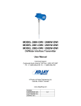
Model: 2882-OWS 1.1 Rev: 1.1 Features 1.2 Microprocessor based capacitance Controller Relay and 4/20mA alarm output Modbus protocol via RS-485 for access by Arjay handheld, Central Access Panel or compatible system Local Auto calibration or remote calibration via network User specified custom features may be added by contacting Arjay Engineering Ltd. Model Number vs. Voltage Input 1.3 User Manual 2882-OWS-1 100-240 VAC power input 2882-OWS-3 12 VAC power input 2882-OWS-4 24 VAC power input Specifications Power Input: 24 VDC or 12 VDC, 250mA maximum 100-240 VAC, 50/60 Hz, 150mA maximum Note: DC input models must be supplied by Limited Energy power source. Limited Energy means compliance with one of the following requirements: Class 2 circuit according to Canadian Electrical Code, Part, I, C22.1; Class 2 circuit according to National Electrical Code, NFPA-70; Limited Power Supply (LPS) according to IEC 60950-1; Limited-energy circuit according to IEC 61010-1. User Interface: Display & Keypad Two line LCD with display of Alarm Condition and menus Select menu or enter values by keypad Communication Interface: RS-485 Modbus Analog /Relay Outputs: mA Signal Output 4 mA during Normal and 20 mA during an alarm condition, 900 Ohms max (24VDC), Relay Output 2 SPDT relay, dry, N.O. Contact 5 A @ 250 VAC (Resistive) and N.C. Contact 3 A @ 250VAC (Resistive), selectable failsafe or non-failsafe, selectable high or low acting alarm, programmable time delay: 0 – 600 seconds **Note: If Isolation is ordered then relays are not available. Instrument Performance: Setpoint Range Submerge active probe tip to desired alarm point 0 - 1000 pF (most applications are 100pF to 500pF) Accuracy 0.2% of setpoint based on clean interface Resolution 0.05% of setpoint via network display 0.002% of Full Scale capacitance via network display Calibration single point Auto calibration 5