1
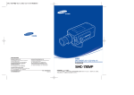
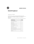
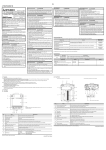
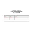
IB-0800385ENG-H-1/2 STARTUP/MAINTENANCE PRECAUTIONS DESIGN PRECAUTIONS GT1155-QTBDQ, GT1155-QTBDA, GT1155-QSBDQ, GT1155-QSBDA, GT1150-QLBDQ, GT1150-QLBDA GT11 Dedicated to Bus Connection General Description MODEL GT11-BUS-U-HW-E MODEL CODE 1D7M70 IB(NA)-0800385ENG-H(1402)MEE This manual describes the part names, dimensions, mounting, and specifications of the product. Before use, read this manual and manuals of relevant products fully to acquire proficiency in handling and operating the product. Make sure to learn all the product information, safety information, and precautions. And, store this manual in a safe place so that you can take it out and read it whenever necessary. Always forward it to the end user. Registration The company name and the product name to be described in this manual are the registered trademarks or trademarks of each company. Effective November 2007 Specifications are subject to change without notice. 2007 Mitsubishi Electric Corporation Japanese Manual Version IB-0800384-G Safety Precautions (Read these precautions before using.) Before using this product, please read this manual and the relevant manuals introduced in this manual carefully and pay full attention to safety to handle the product correctly. The precautions given in this manual are concerned with this product. In this manual, the safety precautions are ranked as "WARNING" and "CAUTION". WARNING Indicates that incorrect handling may cause hazardous conditions, resulting in death or severe injury. Indicates that incorrect handling may cause hazardous conditions, resulting in medium or slight personal injury or physical damage. Depending on circumstances, procedures indicated by "CAUTION" may also be linked to serious results. In any case, it is important to follow the directions for usage. WARNING MOUNTING PRECAUTIONS Be sure to shut off all phases of the external power supply used by the system before mounting or removing the GOT to/from the panel. Not doing so can cause the unit to fail or malfunction. MOUNTING PRECAUTIONS Use the GOT in the environment that satisfies the general specifications described in this manual. Not doing so can cause an electric shock, fire, malfunction or product damage or deterioration. When mounting the GOT to the control panel, tighten the mounting screws in the specified torque range. Undertightening can cause the GOT to drop, short circuit or malfunction. Overtightening can cause a drop, short circuit or malfunction due to the damage of the screws or the GOT. When inserting/removing a CF card into/from the GOT, turn the CF card access switch off in advance. Failure to do so may corrupt data within the CF card. When inserting a CF card into the GOT, push it into the insertion slot until the CF card eject button will pop out. Failure to do so may cause a malfunction due to poor contact. When removing a CF card from the GOT, make sure to support the CF card by hand, as it may pop out. Failure to do so may cause the CF card to drop from the GOT and break. Remove the protective film of the GOT.When the user continues using the GOT with the protective film, the film may not be removed. Operate and store the GOT in environments without direct sunlight, high temperature, dust, humidity, and vibrations. When using the GOT in the environment of oil or chemicals, use the protective cover for oil. Failure to do so may cause failure or malfunction due to the oil or chemical entering into the GOT. WARNING WIRING PRECAUTIONS Some failures of the GOT or cable may keep the outputs on or off. Some failures of a touch panel may cause malfunction of the input objects such as a touch switch. An external monitoring circuit should be provided to check for output signals which may lead to a serious accident. Not doing so can cause an accident due to false output or malfunction. If a communication fault (including cable disconnection) occurs during monitoring on the GOT, communication between the GOT and programmable controller CPU is suspended and the GOT becomes inoperative. The programmable controller CPU goes down, and then the GT1155-QTBDQ, GT1155-QTBDA, GT1155-QSBDQ, GT1155-QSBDA, GT1150-QLBDQ, and GT1150-QLBDA become inoperative. A system where the GOT is used should be configured to perform any significant operation to the system by using the switches of a device other than the GOT on the assumption that a GOT communication fault will occur. Not doing so can cause an accident due to false output or malfunction. Do not use the GOT as the warning device that may cause a serious accident. An independent and redundant hardware or mechanical interlock is required to configure the device that displays and outputs serious warning. Failure to observe this instruction may result in an accident due to incorrect output or malfunction. Incorrect operation of the touch switch(s) may lead to a serious accident if the GOT backlight is gone out. When the GOT backlight goes out, the POWER LED flickers (green/orange) and the display section turns black and causes the monitor screen to appear blank, while the input of the touch switch(s) remains active. This may confuse an operator in thinking that the GOT is in "screensaver" mode, who then tries to release the GOT from this mode by touching the display section, which may cause a touch switch to operate. Note that the following occurs on the GOT when the backlight goes out. - The POWER LED flickers (green/orange) and the monitor screen appears blank Be sure to shut off all phases of the external power supply used by the system before wiring. Failure to do so may result in an electric shock, product damage or malfunctions. Always ground the FG terminal of the GOT power to the functional ground conductor.Failuer to do so may cause electric shocks and malfunctions. Terminal screws which are not to be used must be tightened always at torque 0.5 to 0.8 N·m. Otherwise there will be a danger of short circuit against the solderless terminals. Use applicable solderless terminals and tighten them with the specified torque. If any solderless spade terminal is used, it may be disconnected when the terminal screw comes loose, resulting in failure.less terminals. Correctly wire the GOT power supply section after confirming the rated voltage and terminal arrangement of the product. Not doing so can cause a fire or failure. Tighten the terminal screws of the GOT power supply section in the specified torque range. Undertightening can cause a short circuit or malfunction. Overtightening can cause a short circuit or malfunction due to the damage of the screws or the GOT. Exercise care to avoid foreign matter such as chips and wire offcuts entering the GOT. Not doing so can cause a fire, failure or malfunction. The module has an ingress prevention label on its top to prevent foreign matter, such as wire offcuts, from entering the module during wiring. Do not peel this label during wiring. Before starting system operation, be sure to peel this label because of heat dissipation. Plug the communication cable into the connector of the connected unit and tighten the mounting and terminal screws in the specified torque range. Undertightening can cause a short circuit or malfunction. Overtightening can cause a short circuit or malfunction due to the damage of the screws or unit. Plug the QnA/ACPU/Motion controller (A series) bus connection cable by inserting it into the connector of the connected unit until it "clicks". After plugging, check that it has been inserted snugly. Not doing so can cause a malfunction due to a contact fault. TEST OPERATION PRECAUTIONS WARNING DISPOSAL PRECAUTIONS When power is on, do not touch the terminals. Doing so can cause an electric shock or malfunction. Correctly connect the battery connector. Do not charge, disassemble, heat, shortcircuit, solder, or throw the battery into the fire. Doing so will cause the battery to produce heat, explode, or ignite, resulting in injuly and fire. Before starting cleaning or terminal screw retightening, always switch off the power externally in all phases. Not switching the power off in all phases can cause a unit failure or malfunction. Undertightening can cause a short circuit or malfunction. Overtightening can cause a short circuit or malfunction due to the damage of the screws or unit. Contents Manual Number (Model Code) Describes the GT11 hardware-relevant content such as part names, external dimensions, mounting, power supply wiring, specifications, and introduction to option devices. JY997D17501 (09R815) SH-080868ENG (1D7MC2) GT Designer3 Version1 Screen Design Manual Describes methods of the GT Designer3 installation operation, basic operation for drawing (Fundamentals) 1/2, 2/2 and transmitting data to GOT1000 series (sold separately) *1 SH-080866ENG (1D7MB9) GT Designer3 Version1 Screen Design Manual (Functions) 1/2, 2/2 Describes specifications and settings of the object functions used in GT Designer3 (sold separately) *1 SH-080867ENG (1D7MC1) GOT1000 Series User's Manual (Extended Functions, Option Functions) for GT Works3 Describes extended functions and option functions applicable to GOT series. (sold separately) *1 SH-080863ENG (1D7MB3) *1 For relevant manuals, refer to the PDF manuals stored in the CD-ROM for the drawing software used. For details of a programmable controller to be connected, refer to the programmable controller user's manual respectively. Bundled Items Product Name Model Name Specifications GT1155-QTBDQ 320 240 dots, TFT color LCD (256 colors), built-in battery and backlight, built-in bus interface for connecting to the QCPU (Q mode) and motion controller CPU (Q series), built-in serial interface GT1155-QTBDA 320 240 dots, TFT color LCD (256 colors), built-in battery and backlightm built-in bus interface for connecting to the QnACPU, ACPU, and motion controller CPU (A series), built-in serial interface GT1155-QSBDQ 320 240 dots, STN color LCD (256 colors), built-in battery and backlightm, built-in bus interface for connecting to the QCPU (Q mode) and motion controller CPU (Q series), built-in serial interface GT1155-QSBDA 320 240 dots, STN color LCD (256 colors), built-in battery and backlight, built-in bus interface for connecting to the QnACPU, ACPU, and motion controller CPU (A series), built-in serial interface GT1150-QLBDQ 320 240 dots, STN monochrome LCD (black/white, 16 scales), built-in battery and backlight, built-in bus interface for connecting to the QCPU (Q mode) and motion controller CPU (Q series), built-in serial interface GT1150-QLBDA 320 240 dots, STN monochrome LCD (black/white, 16 scales), built-in battery and backlight, built-in bus interface for connecting to the QnACPU, ACPU, and motion controller CPU (A series), built-in serial interface GOT Bundled item 3. SPECIFICATIONS 3.1 General Specifications Quantity Item Display section Zone d'affichage Other than display section Autre que la zone d'affichage Storage ambient temperature Operating ambient temperature Température ambiante de fonctionnement Operating ambient humidity*1 Storage ambient humidity*1 5) 6) Battery cover opened 3) 7) 10) 11) 1) 2) 12) Power supply terminal layout 5) 9) 3) 8) MITSUBISHI 3) CF card cover opened 3) 4) Shock resistance Quantity GT11 General Description (This manual) 1 Specifications 0 to 50C 0 à 50C 0 to 55C (When mounted horizontaly), 0 to 50C (When mounted verticaly) 0 à 55C (montage horizontal), 0 à 50C (montage vertical) -20 to 60C 10 to 90% RH, non-condensing 10 to 90% RH, non-condensing Conforms to JIS B3502 and IEC61131-2 Vibration resistance 4) Bundled item 4 2.2 Back Panel 3) 이 기기는 업무용 (A 급 ) 전자파적합기기로서 판매자 또는 사용자는 이 점을 주 의하시기 바라며 , 가정외의 지역에서 사용하는 것을 목적으 로 합니다 . (The product is for business use (Class A) and meets the electromagnetic compatibility requirements. The seller and the user must note the above point, and use the product in a place except for home.) GOT1000 Series Connection Manual (Mitsubishi Describes system configurations of the connection method applicable to GOT1000 series Products) for GT Works3 and cable creation method (sold separately) *1 1) Improved monitoring performance and connectivity to FA devices - High speed monitoring through high speed communication at maximum of 115.2kbps. - Multiple languages are displayed using the Unicode2.1-compatible fonts and beautiful characters are drawn using the TrueType and high quality fonts. - High speed display and high speed touch switch response. 2) More efficient GOT operations including screen design, startup, adjustment, management and maintenance works - The 3MB user memory is included as standard. - Font installation is available to increase the system fonts. 3) Enhanced support of FA setup tools - Transferring or monitoring the sequence programs using the personal computer connected to GOT, during direct connection to Q, QnA or A series programmable controller CPU (FA Transparent function). - The USB connector is positioned on the GOT front. This enables the system startup to be performed more efficiently using FA device setup tool, and eliminates the indirect works (opening and closing the control panel, cable replacement, cable rewiring) in order to improve the working efficiency. 1) 2) This product complies with the Radio Waves Act (South Korea). Note the following when using the product in South Korea. Manual name 1. FEATURES GOT 1000 Compliance with the Radio Waves Act (South Korea) The following manuals are relevant to this product. When these loose manuals are required, please consult with our local distributor. Mounting brackets GRAPHIC OPERATION TERMINAL When transporting lithium batteries, make sure to treat them based on the transport regulations. (Refer to the User's Manual of the GOT to be used for details of the regurated models.) Make sure to transport the GOT main unit and/or relevant unit(s) in the manner they will not be exposed to the impact exceeding the impact resistance described in the general specifications of the User's Manual of the GOT to be used, as they are precision devices. Failure to do so may cause the unit to fail. Check if the unit operates correctly after transportation. Manuals Before performing the test operations of the user creation monitor screen (such as turning ON or OFF bit device, changing the word device current value, changing the settings or current values of the timer or counter, and changing the buffer memory current value), read through the manual carefully and make yourself familiar with the operation method. During test operation, never change the data of the devices which are used to perform significant operation for the system. False output or malfunction can cause an accident. 2.1 Front Panel TRANSPORTATION PRECAUTIONS Do not disassemble or modify the unit. Doing so can cause a failure, malfunction, injury or fire. Do not touch the conductive and electronic parts of the unit directly. Doing so can cause a unit malfunction or failure. The cables connected to the unit must be run in ducts or clamped. Not doing so can cause the unit or cable to be damaged due to the dangling, motion or accidental pulling of the cables or can cause a malfunction due to a cable connection fault. When unplugging the cable connected to the unit, do not hold and pull the cable portion. Doing so can cause the unit or cable to be damaged or can cause a malfunction due to a cable connection fault. Do not drop the module or subject it to strong shock. A module damage may result. Do not drop or give an impact to the battery mounted to the unit. Doing so may damage the battery, causing the battery fluid to leak inside the battery. If the battery is dropped or given an impact, dispose of it without using. Before touching the unit, always touch grounded metal, etc. to discharge static electricity from human body, etc. Not doing so can cause the unit to fail or malfunction. Replace battery with GT11-50BAT by Mitsubishi electric Co.only. Use of another battery may present a risk of fire or explosion. Dispose of used battery promptly. Keep away from children. Do not disassemble and do not dispose of in fire. WARNING 2. PART NAME When disposing of the product, handle it as industrial waste. When disposing of batteries, separate them from other wastes according to the local regulations. (Refer to the User's Manual of the GOT to be used for details of the battery directive in the EU member states.) STARTUP/MAINTENANCE PRECAUTIONS GT11 User's Manual (sold separately)*1 WIRING PRECAUTIONS WARNING DESIGN PRECAUTIONS Do not bundle the control and communication cables with main-circuit, power or other wiring. Run the above cables separately from such wiring and keep them a minimum of 100mm (3.94in.) apart.Not doing so noise can cause a malfunction. Do not press the GOT display section with a pointed material as a pen or driver.Doing so can result in a damage or failure of the display section. Turn on the controllers and the network devices to be ready for communication before they communicate with the GOT.Failure to do so can cause a communication error on the GOT. Under intermittent vibration Under continuous vibration Frequency 5 to 8.4Hz 8.4 to 150Hz 5 to 8.4Hz 8.4 to 150Hz Acceleration -9.8m/s2 -4.9m/s2 Half-amplitude 3.5mm -1.75mm -- Sweep Count 10 times each in X, Y and Z directions Conforms to JIS B3502, IEC 61131-2 (147 m/s2, 3 times each in X, Y and Z directions) No greasy fumes, corrosive gas, flammable gas, excessive conductive dust, and direct sunlight (Same as storage atmosphere) Operating atmosphere Operating altitude*2 Installation location 2000 m (6562 ft) max. Overvoltage category*3 Inside control panel II or less Pollution degree*4 Cooling method 2 or less Self-cooling *1 The wet-bulb temperature is 39C or less for STN LCDs. *2 Do not use or store the GOT under pressure higher than the atmospheric pressure of altitude 0m (0ft.). Failure to observe this instruction may cause a malfunction. *3 This indicates the section of the power supply to which the equipment is assumed to be connected between the public electrical power distribution network and the machinery within the premises.Category II applies to equipment for which electrical power is supplied from fixed facilities. The surge voltage withstand level for up to the raged voltage of 300 V is 2500 V. *4 This index indicates the degree to which conductive material is generated in the environment where the equipment is used. In pollution degree 2, only non-conductive pollution occurs but temporary conductivity may be produced due to condensation. 3.2 Performance Specifications No 1) Name Display screen Specifications Displays the utility screen and the user creation screen. GT1155-QTBDQ,GT1155-QTBDA •••320 240 dots, TFT color liquid crystal GT1155-QSBDQ,GT1155-QSBDA •••320 240 dots, STN color liquid crystal GT1150-QLBDQ,GT1150-QLBDA •••320 240 dots, STN monochrome(white/black) liquid crystal, 16 scales 2) Touch key For operating the touch switches in the utility screen and the user creation screen 3) USB interface USB interface for connecting a personal computer (OS installation, project data download, transparent) 4) USB environmental Opens/Closes when the USB interface is used. protection cover 5) Lit in green : Power is correctly supplied Lit in orange : Screen saving Blinking in orange/green : Blown backlight bulb Not lit : Power is not supplied POWER LED For the personal computer connection, refer to the following. GT Designer3 Version1 Screen Design Manual (Fundamentals) 1/2, 2/2 No 1) Name BUS interface Specifications Item For connecting to the QCPU (Q mode) and motion controller CPU (Q series) with the GT1155-QTBDQ, GT1155-QSBDQ, and GT1150-QLBDQ For connecting to the QnACPU, ACPU, and motion controller CPU (A series) with the GT1155-QTBDA, GT1155-QSBDA, and GT1150-QLBDA 2) For connecting to a controller (bar code reader) or personal RS-232 interface computer (OS install, project data download, transparent) (D-sub 9-pin male) 3) Hole for unit installation fitting 4) Rating plate(nameplate) 5) CF card access LED ON: The CF card is accessed. OFF: The CF card is not accessed. 6) CF card access switch Switch for disabling the access to the CF card before removing the CF card from the GOT ON :The CF card is accessed. (CF card removal prohibited) OFF :The CF card is not accessed. (CF card removal available) Display section*1 Hole for the inserting installation fittings (accessory) during the GOT installation to the panel (4 holes at top and bottom) Type Screen size Resolution 320 240 dots Display size W115(4.53) H86(3.39)[mm](inch) Display character 16-dot standard font: 20 characters 15 lines, 12-dot standard font: 26 characters 20 lines (Horizontal format) 256 colors Monochrome (white/black), 16 scales Left/Right: 70 degrees, Top: 70 degrees, Left/Right: 50 degrees, Top: 50 degrees, Left/Right: 45 degrees, Top: 20 degrees, Bottom: 50 degrees (Horizontal format) Bottom: 70 degrees (Horizontal format) *6 Bottom: 40 degrees (Horizontal format) Display color Display angle 400[cd/m2] 8-level adjustment Life*2 Approx. 50,000h (Operating ambient temperature of 25 ) Cold cathode fluorescent tube (irreplaceable by a user) backlight shutoff detection function is included. Backlight off/screen saving time can be set. Approx. 54,000h or longer, Guaranteed: 1 Approx. 75,000h or longer, Guaranteed: 1 year (Time for display intensity reaches year (Time for display intensity reaches 50% at the operating ambient temperature of 50% at the operating ambient temperature of 25 ) 25 ) Life 16-level adjustment 380[cd/m2] GT1150-QLBDQ GT1150-QLBDA STN monochrome (white/black) liquid crystal Contrast adjustment Intensity of LCD only Intensity adjustment Backlight Touch panel Specifications GT1155-QSBDQ GT1155-QSBDA STN color liquid crystal GT1155-QTBDQ GT1155-QTBDA TFT color liquid crystal 5.7" Number of touch keys 300 keys/screen (Matrix structure of 15 lines 20 columns) Key size Minimum 16 16 dots (per key) Number of points touched simultaneously Life 220[cd/m2] 7) CF card cover Open or close when inserting or removing the CF card. 8) Battery cover Open or close when replacing the battery. 9) Power terminal Power terminal and FG terminal (for power supply (24VDC) to GOT and grounding) 10) CF card interface Interface for installing the CF card to GOT 11) CF card eject button Button for removing the CF card Battery GT11-50BAT battery for storing clock data, alarm history and recipe data (The project data is stored in the built-in flash memory.) Buzzer output Environmental protective structure*4 Approx. 5 years (Operating ambient temperature of 25 ), Guaranteed: 1 year Single tone (tone length adjustable) Equivalent to IP67 (JEM1030) (front section) when the USB environmental protective cover is attached External dimensions W167(6.57) H135(5.32) D65(2.56)[mm](inch)(Excluding USB environmental protective cover) 12) Battery For the connection to the programmable controller or personal computer, refer to the following. GOT1000 Series Connection Manual (Mitsubishi Products) for GT Works3 Memory C drive*3 Life (Number of write times) D drive Backup target Life Panel cutting dimensions Maximum of 2 points 1 million times or more (operating force 0.98N max.) Flash memory (Internal), for storing project data (3Mbytes) and OS 100,000 times SRAM (Internal), 512kbyes (battery backup) GT11-50BAT lithium battery Clock data, alarm history and recipe data W153 (6.03) H121(4.77)[mm] (inch) Weight 0.9kg (Excluding mounting fixtures) Compatible software package GT Designer2 Version2 or later*5 *1 Bright dots (always lit) and dark dots (unlit) may appear on a liquid crystal display panel. It is impossible to completely avoid this symptom, as the liquid crystal display comprises of a great number of display elements. Flickers may be observed depending on the display color. Please note that these dots appear due to its characteristic and are not caused by product defect. *2 The GOT screen saving/backlight off function prevents images from becoming permanently etched on the display screen and increases the backlight life. *3 ROM in which new data can be written without deleting the written data. *4 Compliant with IP67 when the USB environmental protection cover is attached. Not compliant when a USB cable is connected. Note that this does not guarantee all users' operation environment. 3.5 External Dimensions USB CF card 3.4 Power Supply Specifications Item Specifications GT1155-QTBDQ GT1155-QSBDQ GT1155-QTBDA GT1155-QSBDA 24VDC (+10% -15%), ripple voltage 200mV or less 1.0A 11.16W (465mA/24VDC) or less 9.72W (405mA/24VDC) or less 5.04W (210mA/24VDC) or less 26A or less (26.4V) 4ms 28.5 (1.13) 110 (4.33) Panel thickness: 5mm(0.2") or less 152 (5.99) 4. EMC AND LOW VOLTAGE DIRECTIVE For the products sold in European countries, the conformance to the EMC Directive, which is one of the European Directives, has been a legal obligation since 1996. Also, conformance to the Low Voltage Directive, another European DIrectives, has been a legal obligation since 1997. Manufacturers who recognize their products must conform to the EMC and Low Voltage Directive are required to declare that their products conform to these Directives and put a "CE mark" on their products. Authorized representative in Europe Authorized representative in Europe is shown below Name :Mitsubishi Electric Europe BV Address:Gothaer strase 8, 40880 Ratingen, Germany Unit: mm (inch) over the page). Standard Remark EMI Compliance with all relevant aspects of the standard. (Radiated Emissions) EMS Compliance with all relevant aspects of the standard. (ESD,RF electromagnetic field, EFTB, Surge, R F conducted disturbances and Power frequency magnetic field) EN61131-2 : 2007 Programmable controllers - Equipment, requirement and tests 4.1 Requirements for Conformance to EMC Directive The EMC Directive specifies that products placed on the market must "be so constructed that they do not cause excessive electromagnetic interference (emissions) and are not unduly affected by electromagnetic interference (immunity)". The applicable products are requested to meet these requirements. The sections 4.1.1 through 4.1.3 summarize the precautions on conformance to the EMC Directive of the machinery constructed using the GOT. The details of these precautions has been prepared based on the requirements and the applicable standards control. However, we will not assure that the overall machinery manufactured according to these details conforms to the above-mentioned directives. The method of conformance to the EMC Directive and the judgment on whether or not the machinery conforms to the EMC Directive must be determined finally by the manufacturer of the machinery. 0.5 to 0.8[Nm] *1 The GOT continues to operate even upon 5ms or shorter instantaneous power failure. The GOT stops operating if there is extended power failure or voltage drop, while it automatically resumes operation as soon as the power is restored. *2 A surge absorber is connected between the power supply and earth terminal so that the GOT does not malfunction due to applied lightning surge noise. Values without a surge absorber are described for the dielectric withstand voltage and the insulation resistance. 4.1.1 #4-40UNC (Inch screw type) Panel thickness: 5mm(0.2") or less 4 5 (0.16) (0.20) 152 (5.99) 0.75 to 2[mm2] Solderless terminal for M3 screw RAV1.25-3, V2-N3A, FV2-N3A 120 (4.73) 135 (5.32) 120 (4.73) 135 (5.32) 110 (4.33) 4 5 (0.16) (0.20) GT1150-QLBDQ GT1150-QLBDA Input power supply voltage Fuse (built-in, not exchangeable) Power consumption 7.92W (330mA/24VDC) or less At backlight off Inrush current Permissible instantaneous power Within 10ms failure time*1 Noise immunity Noise voltage: 500Vp-p, Noise width: 1s (by noise simulator of 25to 60Hz noise frequency) 500VAC for 1 minute (across power supply terminals and earth) Dielectric withstand voltage*2 10M or larger by a 500VDC insulation resistance tester (across power supply terminals and earth) Insulation resistance*2 Applicable wire size Applicable solderless terminal Applicable tightening torque (Terminal block terminal screw) 28.5 (1.13) #4-40UNC (Inch screw type) 62 (2.44) RS-232 167 (6.58) 110 (4.33) 21 (0.83) M2 (Metric screw type) 10 (0.40) Built-in interface 28.5 (1.13) 6 (0.24) 48 (1.89) 65 (2.56) BUS Specifications GT1155-QTBDQ GT1155-QTBDA GT1155-QSBDQ GT1155-QSBDA GT1150-QLBDQ GT1150-QLBDA Bus interface for connecting to the QCPU (Q mode) and motion controller CPU (Q series) 1ch Application : For communicating with a programmable controller Bus interface for connecting to the QnACPU, ACPU, and motion controller CPU (A series) 1ch Application : For communicating with a programmable controller Conforming to serial RS232 standard, 1ch Transmission speed: 115,200/57,600/38,400/19,200/9,600/4,800bps Connector shape : D-sub 9-pin (Male) Application : Bar code reader connection, Personal computer communication (Project data upload/download, OS installation, transparent function) Conforming to serial USB (Full Speed 12Mbps), device, 1ch Application: Personal computer communication (Project data upload/download, OS installation, transparent function) Conforming to PCMCIA, compact flash slot, 1ch Connector shape : Dedicated for TYPE I Application : Data transfer, data storage 62 (2.44) Item GT1155-QTBDA, GT1155-QSBDA, GT1150-QLBDA 10 (0.40) 28.5 (1.13) 3.3 Built-in Interface Specifications 167 (6.58) 110 (4.33) 21 (0.83) 10 (0.40) GT1155-QTBDQ, GT1155-QSBDQ, GT1150-QLBDQ 10 (0.40) *6 For the GT1155-QSBDQ, when its hardware version is Z or earlier, the specifications of the liquid crystal display are as follows. Left/Right: 55 degrees, Top: 65 degrees, Bottom: 70 degrees For the GT1155-QSBDA, when its hardware version is X or earlier, the specifications of the liquid crystal display are as follows. Left/Right: 55 degrees, Top: 65 degrees, Bottom: 70 degrees 6 (0.24) 48 (1.89) 65 (2.56) *5 For the GT1155-QSBDA, use GT Designer2 Version2 with the version 2.59M or later. Standards applicable to the EMC Directive The following products have shown compliance through direct testing (to the identified standards) and design analysis (forming a technical construction file) to the European Directive for Electromagnetic Compatibility (89/336/EEC) when used as directed by the appropriate documentation Type :Programmable Controller (Open Type Equipment) Models :MELSEC GOT series products, identified here, manufactured from January 7th, 2008 GT1155-QTBDQ, GT1155-QTBDA, GT1155-QSBDQ, GT1155-QSBDA, GT1150-QLBDQ, GT1150-QLBDA (For this product see note under and 4.2.1 About the cable used Connect and wire GOT equipment as instructed below. If the GOT equipment is configured in a way that differs from the following instructions then the system will not comply with EMC directives. Bus connection cable The following products are used in the EMC specification compatibility test conducted by Mitsubishi Electric Corporation. ZCAT3035-1330 ferrite core manufactured by TDK corporation AD75CK-type cable clamp manufactured by MITSUBISHI Zipper tube SHNJ type manufactured by Zippertubing(Japan),Ltd. GOT Unit Existing Cables GT1155QTBDQ, GT1155QSBDQ, GT1150QLBDQ GT15-QC B,GT15-QC BS modified as shown in EX.1. Peel the sheath at both ends of the cable, and expose the shield braided wire for grounding. (For grounding with clamps.(refer to Section 4.2.3.)) GT1155QTBDA, GT1155QSBDA. GT1150QLBDA 4.1.3 Grounding It is necessary to use the GOT grounding terminal only when it is in the grounded condition. Be sure to ground the grounding for the safety reasons and EMC Directives. Functional grounding : Improves the noise resistance. Method to connect the power wire and ground wire 1) GT1155-QTBDQ, GT1155-QTBDA, GT1155-QSBDQ, GT1155-QSBDA, GT1150-QLBDQ, GT1150-QLBDA Twist the 24VDC cables to connect to the GT1155-QTBDQ, GT1155-QTBDA, GT1155-QSBDQ, GT1155-QSBDA, GT1150-QLBDQ, and GT1150-QLBDA. The ferrite filter is not required for the 24VDC cables. the GT1155-QTBDQ, GT1155-QTBDA, GT1155-QSBDQ, GT1155-QSBDA, GT1150-QLBDQ, and GT1150-QLBDA unit requires an additional ferrite filter to be attached to the 24V DC power supply cables. The filter should be attached in a similar manner as shown in the figure opposite, i.e. the power cables are wrapped around the filter. However, as with all EMC situations the more correctly applied precautions the better the systems Electro-magnetic Compatibility. The ferrite recommended is a TDK ZCAT3035-1330 or similar. The ferrite should be placed as near to the 24V DC terminals of the the GT1155-QTBDQ, GT1155-QTBDA, GT1155QSBDQ, GT1155-QSBDA, GT1150-QLBDQ, and GT1150-QLBDA as possible (which should be within 75mm of the GOT terminal). User Made Cables GT15-C BS,cGT15-C EXSS-S1 modified as shown in EX.2. Peel the sheath at both ends of the cable, and expose the shield braided wire for grounding. (For grounding with clamps.(refer to Section 4.2.3.)) Other bus connection cables modified as shown in EX.3. Wind cable shield material around the cable, and pull out the grounding braided wire of the cable shield material. Attach the ferrite core to the cable in the specified position and insert the braided wire for grounding into the ferrite core. The cable need to be independently tested by the user to demonstrate EMC compatibility when they are used with the GOT, the PLC of MELSEC-Q series, MELSECQnA series, and MELSEC-A series. INPUT 24V DC - + Ferrite Core (ZCAT3035-1330) 4.2.3 1) 2) Grounding the cable Braided shield Cable clamps For the cable clamp attaching details, refer to AD75CK-type Cable Clamping Instruction Manual <IB-68682>. 360 (14.17) or less Unit: mm (inch) GOT units 152 (5.99) A Unit: mm (inch) GOT units Programmable controller /GOT units Mount the GOT onto the control panel while considering the following control panel inside dimensions. B 1) Ground the braided shield portion of the cable to the control panel with the cable clamp (AD75CK). Programmable controller 40 40 (1.57) (1.57) 5.1 Control Panel Inside Dimensions for Mounting GOT Up to 75mm EX.1 360 (14.17) or less 5. INSTALLATION Use the bus connection cable to ground the cable and grounding wire to the control panel where the GOT and base unit are installed. EX.2 Pollution level 1:An environment where the air is dry and conductive dust does not exist. Pollution level 2:An environment where conductive dust does not usually exist, but occasional temporary conductivity occurs due to the accumulated dust. Generally, this is the level for inside the control box equivalent a control room or on the floor of a typical factory. Pollution level 3:An environment where conductive dust exits and conductivity may be generated due to the accumulated dust. An environment for a typical factory floor. Pollution level 4:Continuous conductivity may occur due to rain, snow, etc. An outdoor environment. 4.2.2 a) For GT15-C EXSS-1 and GT15-C BS Ground the ground wire to the FG terminal of the GOT power supply section. Bus connection cable Model Name A B GT1155-QTBDQ GT1155-QSBDQ GT1150-QLBDQ 56 (2.20) 40 (1.57) GT1155-QTBDA GT1155-QSBDA GT1150-QLBDA 38 (1.50) 40 (1.57) No Name 1) Bus connection cable 2) Personal computer connection cable/bar code reader connection cable Applicable cable Some cables may need to be longer than the specified dimensions when connecting to the GOT. Therefore, consider the connector dimensions and bending radius of the cable as well for installation. 5.2 Panel Cutting Dimensions Make holes in the panel according to the dimensions list below. Also, ensure 10mm spaces in upper and lower parts of the panel for mounting fixtures. +2 +0.08" 153-0 (6.03" -0 ) 10(0.4") or more 60 (2.36) or less 360 (14.17) or less Ground wires (280 (11.0)) 40 (1.57) 40 (1.57) FG wire 60 (2.36) or less 360 (14.17) or less Unit: mm (inch) EX.3 Programmable contoller 80 (3.15) 40 (1.57) or less Ferrite Core (ZCAT3035-1330) Cable shield material Grounding braided wire (200 (7.87)) Grounding braided wire (50 (1.97)) GOT units 80 (3.15) 40 (1.57) or less Unit: mm (inch) 140 (5.52) Connect and wire GOT equipment as instructed below. If the GOT equipment is configured in a way that differs from the following instructions then the system will not comply with EMC directives. TDK 3) ]Electrical shock prevention In order to such as the operators from electric shocks, the control box must have the following functions : a) The control cabinet must be equipped with a lock so that only skilled or qualified personnel. b) The control cabinet must be fitted with advice which automatically stops the power supply when the cabinet is opened. 4) Dustproof and waterproof features The control box also has the dustproof and waterproof functions. Insufficient dustproof and waterproof features lower the insulation withstand voltage, resulting in insulation destruction. The insulation in our GOT is designed to cope with the pollution level 2, so use in an environment with pollution level 2 or better. 4.2 Wiring Precautions the Part which Matches the EMC Directives 120 (4.73) Control cabinet The GOT is an open type device (device installed to another device) and must be installed in a conductive control panel or cabinet. It not only assure the safety but also has a large effect to shut down the noise generated from GOT, on the control panel. 1) Control cabinet a) Use a conductive control cabinet. b) When attaching the control cabinet's top plate or base plate, mask painting and weld so that good surface contact can be made between the cabinet and plate. c) To ensure good electrical contact with the control cabinet, mask the paint on the installation bolts of the inner plate in the control cabinet so that contact between surfaces can be ensured over the widest possible area. d) Earth the control cabinet with a thick wire so that a low impedance connection to ground can be ensured even at high frequencies. (22mm 2 wire or thicker is recommended.) e) Holes made in the control cabinet must be 10 cm (3.94”) diameter or less. If the holes are 10cm (3.94”) or larger, radio frequency noise may be emitted. In addition, because radio waves leak through a clearance between the control panel door and the main unit, reduce the clearance as much as practicable. The leakage of radio waves can be suppressed by the direct application of an EMI gasket on the paint surface. 2) Connection of power and ground wires Ground and power supply wires for the GOT must be connected as described below. a) Provide an earthing point near the GOT. Earth the power supply's FG terminal (FG: Frame Ground) with the thickest and shortest wire possible. (The wire length must be 30cm (11.18”) or shorter.) The FG terminal function is to pass the noise generated in the GOT to the ground, so an impedance that is as low as possible must be ensured. As the wires are used to relieve the noise, the wire itself carries a large noise content and thus short wiring means that the wire is prevented from acting as an antenna. Note) A long conductor will become a more efficient antenna at high frequency. GOT FG terminal b) For other bus connection cables Ground the braided wire for grounding to the control panel by tightening a screw. +0.08" ) 121+2 -0 (4.77" -0 4.1.2 10(0.4") or more Unit: mm (inch) IB-0800385ENG-H-2/2 When mounting the main unit to a control panel or similar, set the display section as shown below. When the temperature inside the control panel is 40 to 55 (Horizontal mount), 40 to 50 (Vertical mount), the mounting angle should be in the range 60 to 105 degrees. The GOT will be deteriorated earlier if it is used at the GOT mounting angle other than back the above. Therefore, the panel GOT temperature inside the 105˚ control panel should be within display section 40 . 60˚ Control panel, etc. montage du GOT 5.3 Position de montage Montez le GOT sur le tableau de commande en tenant compte des dimensions intérieures du tableau de commande ci-dessous. 152 (5,99) A 1) 2) 140 (5,52) 5.4 Control Panel Inside Temperature and Mounting Angle When mounting the GOT, the 80mm (3.15") or more clearances shown on the right must be left from a structure or the other device. Secure 50mm (1.97") or more on the 50mm 50mm left, right and bottom sides of the GOT (1.97") (1.97") or or to structures or other devices. more more Secure 80mm (3.15") or more on the top of the GOT from structures or other devices to allow good ventilation. *1 50mm (1.97") or more If devices (such as a contactor) generating radiated noise or those *1 To use the CF card, leave sufficient generating heat are arranged around distances for removal and installation the GOT, secure 100mm (3.94") or of the CF card. more on the back panel. When using the CF card, secure a sufficient distance on the left side to allow installation and removal of the CF card. [Securing 100mm (3.94") or more is recommended.] 120 (4,73) 5.3 Mounting Position 5.5 Installation Procedure The GOT is designed to be embedded into a panel. Mount the GOT by following the procedure below. For panel cutting dimensions, refer to Section 4.2. Note that the panel thickness should be within 5mm. 1) Inserting into the panel face Insert the GOT from the front side of the panel. B Unité : mm (pouce) Nom du modèle Mounting hole Magnified illustration A B GT1155-QTBDQ GT1155-QSBDQ GT1150-QLBDQ 56 (2,20) 40 (1,57) GT1155-QTBDA GT1155-QSBDA GT1150-QLBDA 38 (1,50) 40 (1,57) 80mm (3,15") ou plus Lors du montage du GOT, il est nécessaire de laisser les espaces indiqués à droite pour une structure ou un autre dispositif. 50mm 50mm Laissez 50mm (1,97") ou plus sur les (1,97") (1,97") ou plus ou plus côtés gauche, droit et inférieur du GOT pour des structures ou d'autres dispositifs. Laissez 80mm (3,15") ou plus sur le 50mm (1,97") ou plus *1 côté supérieur du GOT pour des structures ou d'autres dispositifs afin d'assurer une bonne ventilation. *1 Pour utiliser la carte CF, laissez une Si des dispositifs (comme un distance suffisante pour retirer et insérer contacteur) générant des émissions la carte CF. sonores ou de la chaleur sont placés autour du GOT, laissez 100mm (3,94") ou plus sur le panneau arrière. Lors de l'utilisation de la carte CF, laissez une distance suffisante sur le côté gauche pour pouvoir insérer et retirer la carte CF. [Il est recommandé de laisser 100mm (3,94") ou plus.] 5.4 Température intérieure et angle de montage du tableau de commande Lors du montage du châssis de base sur un tableau de commande ou autre, réglez la zone d'affichage comme indiqué ci-dessous. Lorsque la température à l'intérieur du tableau de commande est comprise entre 40 et 55C (montage horizontal), 40 à 50C (montage vertical), l'angle de montage doit être compris entre 60et 105. Si l'angle de montage est différent de celui indiqué, Panneau le GOT sera détéri oré arrière du GOT plus tôt. Par conséquent, Zone la température à l'intérieur 105° d'affichage du tableau de commande du GOT doit être d'environ 40°C. 60° Tableau de commande, etc. N Mounting fitting Mounting screw Nom 5.5 Procédure d'installation 1) Câble de connexion du bus 2) Câble de connexion de l'ordinateur individuel/câble de connexion du lecteur de code-barres Câble applicable Certains câbles peuvent être plus longs que les dimensions spécifiées lors de la connexion au GOT. Par conséquent, prenez également en compte les dimensions du connecteur et le rayon de courbure du câble pour l'installation. Le GOT est conçu pour s'intégrer dans un panneau. Montez le GOT en suivant la procédure ci-dessous. Pour connaître les cotes de découpe du panneau, référez-vous à la section 5.2. Notez que l'épaisseur du panneau doit être d'environ 5mm. 1) Insertion dans la façade du panneau Insérez le GOT sur la face antérieure du panneau. 5.2 Cotes de découpe du panneau Faites des trous dans le panneau en suivant les dimensions ci-dessous. Veillez à laisser des espaces de 10mm dans les parties supérieure et inférieure du panneau pour les fixations. 2) Fixing the GOT Engage the hook of the mounting fitting (accessory) to the unit fixing hole of the GOT and tighten the screw until the GOT is fixed with the mounting bolt (accessory). +2 +0,08" ) 153-0 (6,03" -0 10 (0,4") ou plus 5. INSTALLATION +0,08" ) 121+2 -0 (4,77" -0 3) A protection film is attached on the display section of GOT prior to shipment. Remove the film when the installation is completed. The GOT will be fixed in 4 upper/lower parts. Tighten the mounting screw with the specified torque. (Failure to do so may distort the panel and make a surface waviness on the protective sheet.) 5.1 Dimensions intérieures du tableau de commande pour le 10 (0,4") ou plus Trou de fixation 2) Fixation du GOT Placez le crochet de l'attache de fixation (accessoire) dans le trou de fixation du GOT et serrez la vis jusqu'à ce que le GOT soit fixé avec le boulon de fixation (accessoire). Le GOT est fixé en 4 points en haut et en bas. Serrez la vis de fixation au couple spécifié. ( N e pas l e f a ir e p eu t dé f orm e r l e panneau et faire onduler le film de protection.) Gros plan Attache de fixation Vis de fixation 3) Un film de protection est placé sur la zone d'affichage du GOT avant livraison. Retirez le film lorsque l'installation est terminée. Unité : mm (pouce) 6. WIRING 7. MAINTENANCE AND INSPECTION 7.3 Battery Replacement Warranty 6.1 Power Supply Wiring The GOT does not include consumable components that will cause the shorten life. However, note that battery life is 5 years and LCD life is 50,000 hours. The life of backlight in GT1155-QTBDQ, GT1155-QTBDA, GT1155-QSBDQ, GT1155-QSBDA is 75,000 hours and that in GT1150-QLBDQ, GT1150-QLBDA is 54,000 hours. It is recommended to replace the battery periodically. (For the replacement of the liquid crystal screen and backlight, please consult your nearest sales office or FA Center.) The battery backs up clock data, alarm history and recipe data. Screen data is stored in the flash memory and data is retained even if the battery is dead. Mitsubishi will not be held liable for damage caused by factors found not to be the cause of Mitsubishi; machine damage or lost profits caused by faults in the Mitsubishi products; damage, secondary damage, accident compensation caused by special factors unpredictable by Mitsubishi; damages to products other than Mitsubishi products; and to other duties. Connect the power terminal on the GOT rear face with the 24VDC terminal of the external power. Use 0.75mm2 or more cables so as not to produce voltage drops. Use solderless terminals for M3 screws, and be sure to tighten the screws with a tightening torque of 0.5 to 0.8Nm. Programmable controller connection cable 7.1 Daily Inspection Daily inspection items No. 2 3 The independent grounding is basically required. Ground the GOT with a ground resistance of 100 or less. If the independent grounding is impossible, carry out the shared grounding as shown in fig.2) below. Use the cable of 2mm2 or more for grounding. Set the grounding point closer to the GOT to make the grounding cable short as possible. GOT Other device Other device GOT GOT (1) Independent ground ...... Best condition No. (3) Common grounding ...... Not allowed Terminal Solderless terminal screw 6.2mm or less 6.2mm or less Retighten screws with screwdriver Not loose Retighten terminal screws Proximate solderless terminals Visual check Proper intervals Correct Loose connectors Visual check Not loose Retighten connector fixing screws Dirt on protection sheet Visual check Not outstanding Replace with new one Foreign material attachment Visual check No foreign Remove clean matter sticking Loose terminal screws Inspection Item Terminal Solderless screw terminal 2 When wiring two cables to one terminal 3 Applicable solderless terminal RAV 1.25-3, V2-N3A and FV2-N3A Connection status Action Model name Battery GT11-50BAT Battery replacement procedure 1) Turn the GOT power off. 2) Open the back cover of the GOT. 3) Remove the old battery from the holder. 4) Disconnect the old battery connector and insert the new battery connector within 30s. (Clock data, alarm history, and recipe data is retained by the GOT condenser for 30 seconds.) 5) Insert the new battery into the holder and close the back cover. For safe use Back cover Holder Connector Back cover Holder Connector How to confirm production year and month The production year and month of the battery built in the purchased GOT can be confirmed by the production No. (serial No.) marked on the GOT main unit. GRAPHIC OPERATION TERMINAL MODEL GT1155-QTBDQ IN 24VDC MITSUBISHI ELECTRIC MADE IN JAPAN 0 to 50 For use in control panel, temperature inside control panel is ambient temperature 24VDC Measure 20.4 to voltage across 26.4VDC terminals. Change supply power Loose terminal screws Retighten screws with screwdriver Not loose Retighten terminal screws Proximate solderless terminals Visual check Proper intervals Correct Loose connectors Visual check Not loose Retighten connector fixing screws Power supply voltage check Product name POWER MAX 00W SERIAL 00007201DP00001-A Criterion Ambient Make temperature measurement 0 to Other with portions 55 Surrounding thermometer environment or hygrometer Ambient 10 to 90%RH Measure humidity corrosive gas No corrosive Atmosphere gas 3.2 When wiring one cable to one terminal Inspection Method Display section 1) Recommended terminal shape 3.2 Check for Securely loose mounting mounted screws. Yearly or half-yearly inspection items The following inspection should also be performed when equipment has been moved or modified or the wiring changed. 1 (2) Shared grounding ...... Good condition Action 7.2 Periodic Inspection Other device Grounding Grounding Criterion Refer to the following for the model names of the protection sheet or the replacement procedure. GT11 User’s Manual 24VDC power supply Grounding Inspection Method Retighten screws within the specified torque range GOT mounting status Connection status 1 Inspection Item Usage status Connection cable for personal computer or bar code reader Battery model name GT11 is shipped with the following battery. Year (example: 2007) last digit Day (example: 1st) 1 to 31: 1st to 31st Month (example: Jun.). 1 to 9: Jan. to Sep., X: Oct., Y: Nov., Z: Dec. Battery life Approximate battery life: 5 years (ambient temperature: 25 ) [Guaranteed for 1 year] Battery replacement: In 4 to 5 years Approximate life is 5 years, but life may be shorter depending on the ambient temperature, therefore, note that the battery must be replaced in 4 to 5 years. Make sure to purchase a new battery as needed as it self-discharges. Battery status can be confirmed on a GOT utility screen. For details of battery status or how to output alarm, refer to the following: GT11 User’s Manual • This product has been manufactured as a general-purpose part for general industries, and has not been designed or manufactured to be incorporated in a device or system used in purposes related to human life. • Before using the product for special purposes such as nuclear power, electric power, aerospace, medicine or passenger movement vehicles, consult with Mitsubishi. • This product has been manufactured under strict quality control. However, when installing the product where major accidents or losses could occur if the product fails, install appropriate backup or failsafe functions in the system. Country/Region Sales office/Tel U.S.A Mitsubishi Electric Automation Inc. 500 Corporate Woods Parkway Vernon Hills, IL 60061, U.S.A. Tel : +1-847-478-2100 Brazil MELCO-TEC Rep. Com.e Assessoria Tecnica Ltda. Rua Correia Dias, 184, Edificio Paraiso Trade Center-8 andar Paraiso, Sao Paulo, SP Brazil Tel : +55-11-5908-8331 Germany Mitsubishi Electric Europe B.V. German Branch Gothaer Strasse 8 D-40880 Ratingen, GERMANY Tel : +49-2102-486-0 U.K Mitsubishi Electric Europe B.V. UK Branch Travellers Lane, Hatfield, Hertfordshire., AL10 8XB, U.K. Tel : +44-1707-276100 Italy Mitsubishi Electric Europe B.V. Italian Branch Centro Dir. Colleoni, Pal. Perseo-Ingr.2 Via Paracelso 12, I-20041 Agrate Brianza., Milano, Italy Tel : +39-039-60531 Spain Mitsubishi Electric Europe B.V. Spanish Branch Carretera de Rubi 76-80, E-08190 Sant Cugat del Valles, Barcelona, Spain Tel : +34-93-565-3131 France Mitsubishi Electric Europe B.V. French Branch 25, Boulevard des Bouvets, F-92741 Nanterre Cedex, France Tel : +33-1-5568-5568 South Africa Circuit Breaker Industries Ltd. Private Bag 2016, ZA-1600 Isando, South Africa Tel : +27-11-928-2000 Hong Kong Mitsubishi Electric Automation (Hong Kong) Ltd. 10th Floor, Manulife Tower, 169 Electric Road, North Point, Hong Kong Tel : +852-2887-8870 China Mitsubishi Electric Automation (China) Ltd. 4/F Zhi Fu Plazz, No.80 Xin Chang Road, Shanghai 200003, China Tel : +86-21-6120-0808 Taiwan Setsuyo Enterprise Co., Ltd. 6F No.105 Wu-Kung 3rd.Rd, Wu-Ku Hsiang, Taipei Hsine, Taiwan Tel : +886-2-2299-2499 Korea Mitsubishi Electric Automation Korea Co., Ltd. 1480-6, Gayang-dong, Gangseo-ku Seoul 157-200, Korea Tel : +82-2-3660-9552 Singapore Mitsubishi Electric Asia Pte, Ltd. 307 Alexandra Road #05-01/02, Mitsubishi Electric Building, Singapore 159943 Tel : +65-6470-2460 Thailand Mitsubishi Electric Automation (Thailand) Co., Ltd. Bang-Chan Industrial Estate No.111 Moo 4, Serithai Rd, T.Kannayao, A.Kannayao, Bangkok 10230 Thailand Tel : +66-2-517-1326 Indonesia P.T. Autoteknindo Sumber Makmur Muara Karang Selatan, Block A/Utara No.1 Kav. No.11 Kawasan Industri Pergudangan Jakarta - Utara 14440, P.O.Box 5045 Jakarta, 11050 Indonesia Tel : +62-21-6630833 India Messung Systems Pvt, Ltd. Electronic Sadan NO:III Unit No15, M.I.D.C Bhosari, Pune-411026, India Tel : +91-20-2712-3130 Australia Mitsubishi Electric Australia Pty. Ltd. 348 Victoria Road, Rydalmere, N.S.W 2116, Australia Tel : +61-2-9684-7777 HEAD OFFICE : TOKYO BUILDING, 2-7-3 MARUNOUCHI, CHIYODA-KU, TOKYO 100-8310, JAPAN NAGOYA WORKS : 1-14, YADA-MINAMI 5-CHOME, HIGASHI-KU, NAGOYA, JAPAN When exported from Japan, this manual does not require application to the Ministry of Economy, Trade and Industry for service transaction permission. Specifications subject to change without notice. Printed in Japan, February 2014.