1
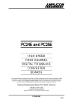
UMC 486DX/ 486DX2/ 486SX Syste111 Board User's Manual CONTENTS PAGE 1. INTRODUCTlON. ....................................................... 1-1 2. GENERAL SPECIFICA7IONS ......................................2-1 3. MEMORYCONFIGURA7ION..................................... 3-1 3.1. 3.2. Memory Bank Configuration .......................................3-1 Possible Memory Configuration................................3-1 4. CPU OPERATING SPEED............................................ .4-1 5. JUMPER SETflNG. .......................................................S-1 6. CONNECTOR PIN ASSlGNMENT.. ............................ 6-1 7. I/O ADDRESS MAPP1NG. .............................................7-1 8. EXPANSION SLOTS ......................................................8-1 9. BIOS SETUP...................................................................9-1 9.1. 9.2. 9.3. 9.4. 9.5 9.6. Warning Information ..................................................... 9-2 Standard CMOSSetup.................................................. 9-3 Auto Configuration with BIOS Defaults ..................... 9-S Auto Configuration with Power-On Defaults.......... 9-6 Advanced CMOS Setup ................................................ 9-7 Change Password.......................................................... 9-10 10. MAIN BOARD LA YOUT.. ........................................ 1O-1 1. INTRODUCTION The manual is prepared for both the users who want to install the 486DX system board in their system and the programmers who want to utilize the 486DX system for special functions. The 486DX system board is based on the 80486DX (or 80486SX) microproces sor and the high performance UMC 82C481B I 82C482A I 82C206 chipset which includes peripheral controller, datal address buffer and advanced memory manager. The system board is fully compatible with the IBM PCI AT. On-board memory can be expandable from 1MB up to 16M bytes (or 48MB if HDSIMM RAM modules are installed). The cache memory size can be configurable as 64K, 128K or 256K. 1-1 2. GENERAL SPECIFICATIONS The 486 system board has the following general specifications: o The 486 system board is based on the 80486DX-33 or 80486SX-25 CPU. o High performance UMC 82C481B / 82C482A / 82C206 486 AT compatible chipset is used. o On-board DRAM sub-system expandable from 1MB to 16MB (or 48MB if HDSIMM are installed). o Support 256KBX9, 1MBX9 or 4MBX9 SIMM memory module.X Support shadow RAM for system BIOS and video BIOS. o AMI AT compatible BIOS is used. o The CPU speed is selectable by jumper or eyboard control. o 3 Programmable timer/counters. o 16 Levels of system interrupts. o 7 Direct Memory Access (DMA) channels. o On-board battery bac up for CMOS configuration table and real time doc. o Six 16-bit expansion slots and two 8-bit expansion slots. 2-1 3. MEMORY CONFIGURATION 3.1. Memory Ban Configuration .. JPS JP9 SMl-4 SM5 X 1-2 Ban 0 Ban 1 & 2 2-3 2-3 Ban 1 Ban 0 1-2 2-3 Ban 2 Ban 0 & 1 Remar : X means don't care 3.2. i. Possible Memory Configuration Jumper Setting UPS Ban 0 SM1-SM4 256Kx9 x 4 256Kx9 x 4 256Kx9 x 4 1Mx9 x 4 256Kx9 x 4 1Mx9 x 4 256Kx9 x 4 1Mx9 x 4 4Mx9 x4 1Mx9 x 4 4Mx9 x4 1Mx9 x 4 4Mx9 x4 = X, JP9 = 1-2) Ban 1 & 2 SM5 256Kx36 512Kx36 1Mx36 1Mx36 2Mx36 2Mx36 4Mx36 4Mx36 SMx36 SMx36 3-1 Total 1M 2M 3M 4M 5M SM 9M 12M 16M 20M 32M 36M 4SM II. Jumper Setting (JP8 Ban 0 Ban 1 SM5 SM1-SM4 256Kx36 256Kx36 1Mx36 256Kx36 1Mx36 4Mx36 1Mx36 4Mx36 II. = 2 - 3, JP9 = 2 - 3) Jumper Setting (JP8 Ban 0 & 1 SM5 512Kx36 512Kx36 512Kx36 2Mx36 2Mx36 2Mx36 8Mx36 8Mx36 256Kx9 x 4 1Mx9 x 4 1Mx9 x 4 4Mx9 x 4 4Mx9 x 4 Total 1M 2M 4M 5M 8M 16M 20M 32M = 1 - 2, JP9 = 2 - 3) Ban 2 SM1-SM4 256Kx9 x 4 1Mx9 x 4 1Mx9 x 4 4Mx9 x 4 4Mx9 x 4 3-2 Total 2M 3M 6M 8M 12M 24M 32M 48M 4. CPU OPERATING SPEED The 486 system board can run at either non-turbo mode or turbo mode. The selection can be done by either a turbo switching button connected to jumper TB SW or using eyboard control. Key-in Sequence Operating Mode Ctrl-Alt_ + Turbo mode CtrLAlt_- Non-turbo mode (: .. 4-1 5. JUMPER SETTING Following are the details specification of jumpers: Reset Reset Switch- - - - - - Short Open Reset the system Normal TBSW Turbo Switch Connector Open Short Non-turbo mode Turbo mode JPS Display Type Selection Short Open CGA Monochrome / EGA / VGA JP7 External/Internal Battery Open Short Select External Battery Select Internal Battery JP2 JPl1 CPU Type 2-3 Open 1-2 1 - 2,3 - 4 2-3 1 - 2, 3 - 4 486DX 486SX 487SX 5-1 WI5 W14 WI7 WI6 W1D wn W13 W12 Cache RAM Tag RAM Cache Size Cacheable Size 8Kx8 U25-32 8Kx8 U25, U27 U29, U31 32Kx8 U25-U32 8Kx8 U24 8Kx8 U24 64K 16MB 128K 32MB 256K 64MB ----- 1-2 1-2 Off 1-2 Off Off Off Off 2-3 1-2 1-2 2-3 On Off Off On 2-3 2-3 2-3 1-2 On On On On 5-2 32Kx8 U24 6. CONNECTOR PIN ASSIGNMENT CN1 Power Connector I 7 8 9 10 11 12 Power Good +5V +12V -12V Ground Ground Ground Ground -5V +5V +5V +5V KB1 Keyboard Connector 1 2 3 5 Cloc Data Spare Ground +5V Spea er Spea er Connector 1 2 3 Spea erNo Connection Ground Spea er + ---- 2 3 4 5 6 4 4 6-1 Keyloc Keyloc & Power LED 1 2 3 4 5 +5V No Connection Ground Keyboard Inhibit Ground TBLEo 1 2 Turbo LED LED + LEo J6 External Battery Connector 1 2 3 3.6V - 4.5V No Connection Ground Ground 4 6-2 7 I/O ADDRESS MAPPING Hex Range Devices Usage 000 - OlP 020 - 03F 040 - OSF 060 - 06F 070 - 07F 080 - 09F OAO - OBF OCO-ODF OFO OFI OF8 - OFF IFO -lF8 200 - 207 278 - 27F 2F8 - 2FF 300 - 31F 360 - 36F 378 - 37F 380 - 38F 3AO-3AF 3BO - 3BF 3CO-3CF 300-30F 3FO - 3F7 3F8 - 3FF DMA Controller 1 Interrupt Controller 1 Timer 8042 ( eyboard) Real-time doc, NMI mas OMA Page register Interrupt Controller 2 DMA Controller 2 Clear Maths Coprocessor Reset Maths Coprocessor Maths Coprocessor Fixed dis Game I/O Parallel printer port 2 Serial port 2 Prototype Card Reserved Parallel printer port 1 SOLC, bisynchronous 2 Bisynchronous 1 Monochrome display and printer adapter Reserved Color/Graphics Adapter Floppy dis ette controller Serial port 1 system system system system system system system system system system system I/O I/O I/O I/O I/O I/O I/O I/O I/O I/O I/O I/O I/O I/O 7-1 8 EXPANSION SLOTS 8.1. 62 pin.va BUS Signal Pin GND RESET DRV +SVdc IRQ9 -SVdc DRQ2 -12Vdc OWS +12Vdc GND -SMEMW -SMEMR -lOW -lOR -DACK3 DRQ3 -DACK1 DRQ1 -REFRESH BUSCLK IRQ7 lRQ6 IRQ5 IRQ4 IRQ3 -DACK2 T/C BALE +5Vdc OSC GND B1 B2 B3 B4 B5 B6 B7 B8 B9 B10 B11 B12 Rear panel B13 B14 B15 B16 B17 I318 B19 B20 B21 B22 B23 B24 B25 B26 B27 B28 B29 B30 B31 8-1 Pin Signal A1 A2 A3 A4 AS A6 A7 A8 A9 A10 All A12 A13 A14 A15 A16 A17 A18 A19 A20 A21 A22 A23 A24 A25 A26 A27 A28 A29 A30 A31 -I/OCHCK SD7 SD6 SDS SD4 SD3 SD2 SD1 SDO -I/O CHRDY AEN SA19 SA18 SA17 SA16 SA15 SA14 SA13 SA12 SAll SA10 SA9 SA8 SA7 SA6 SA5 SA4 SA3 SA2 SAl SAO 1, 8.2. 36 pill I/O BUS Signal Pin -MEM CS16 -I/O CS16 IRQIO IRQll IRQ12 IRQ15 IRQ14 -DACKO DRQO -DACKS DRQS -DACK6 DRQ6 -DACK7 DRQ7 +SVdc -MASTER GND Dl D2 D3 D4 D5 D6 D7 D8 D9 Rear panel Pin Signal C1 SBHE LA23 LA22 LA21 LA20 LA19 LA18 LA17 -MEMR -MEMW SD8 SD9 SDID SDll SD12 SD13 SD14 SD15 C2 C3 C4 C5 C6 C7 C8 C9 CIO Cll C12 C13 C14 CIS C16 C17 C18 DID Dll D12 D13 D14 D1S D16 D17 D18 8-2 9 BIOS SETUP AMI AT compatible BIOS (Basic Input Output System) is supplied along with the 486 system board. The BIOS provides an on-screen interactive configura tion setup utility. This setup utility allows setting of time, date, type of floppy drivers, type of hard disk, type of display adapter, CPU speed, memory configuration, and BIOS shadow memory. The SETUP utility is built-in with the BIOS. It can be invoked by pressing the DEL key as instructed on the screen after the system warmor cold start. A main menu will pop up as follows. BIOS SETUP PROGRAM - AMI BIOS SETUP UTILITIES (C) 1991 American Megatrends Inc., All Rights Reserved I ISTANDARD CMOS SETUP ADV ANCED CMOS SETUP ADV ANCED CHIPSET SETUP AUTO CONFIGURATION WITH BIOS DEFAULTS AUTO CONFIGURATION WITH POWER-ON DEFAULTS CHANGE PASSWORD I-lARD DISK UTILITY WRITE TO CMOS AND EXIT DO NOT WRITE TO CMOS AND EXIT Standard CMOS Setup for Changing Time, Date, Hard Disk Type, etc. ESC. EXIt ...v-71'f- .sel F2/F3. Color FlO. Save & EXIt Use arrow keys to move cursor to the desired selection. For the ease of configuration, you can select "Auto Configuration With BIOS Defaults" first and then go to the "Standard CMOS Setup". You need not go through the "Advanced CMOS Setup" or "Advanced Chipset Setup" unless you have a good technical knowledge of the chipset or want to use some extended features. 9-1 9.1. Warning Infonnation A warning message, shown as below, is displayed each time when one of the first three options (Standard CMOS Setup, Advanced CMOS Setup, and Advanced Chipset Setup) is selected, before any changes are allowed to any of the setup parameters. BIOS SETUP PROGRAM - WARNING INFORMATION (C)1991 American Megatrends Inc., All Rights Reserved Improper Use of Setup may Cause Problems !! If System Hangs, Reboot System and Enter Setup by Pressing the <DEL> key Do any of the following After Entering Setup (i) Alter Options to make System Work (ii) Load BIOS Setup Defaults (iii) Load Power-On Defaults Hit <ESC> to Stop now. Any other key to Continue 9-2 9.2. Standard CMOS Setup Standard CMOS Setup is the first option on the main setup menu. Press ENTER at the highlighted selection to access this option. The screen as below will appear. BIOS SETUP PROGRAM - STANDARD CMOS SETUP (C)1991 American Megatrends Inc., All Rights Reserved Date (nm/date/year) : Mon,IAprl221991 Time (hour/min/sec): 10:42:44 Cyln Hard disk C: type: :17 977 Hard disk D: type : Not Installed Floppy drive A: : 1.2 MB,51/4" Floppy drive B: : 1.44 MB, 31/2" Primary display : VGA/PGA/EGA Keyboard : Installed Base memory Ext. memory Head WPcom 5 300 Sun Mon Tue Wed ~u 31 1 2 3 4 7 8 9 10 11 14 15 16 17 18 21 22 23 24 25 28 29 30 1 2 5 6 7 8 9 Month: Jan, Feb, ........ Dec Date : aI, 02, 03 ....... 31 Year : 1901, 1902 ..... 2099 ESC:Exit ~-71'f-Select F2/F3:Color PU/PD:Modify : 640 KB :OKB Lzone Sect Size 977 17 41ME Fri 5 12 19 26 3 10 Sat 6 13 20 27 4 11 ~ The Standard CMOS Setup utility is used to configure the following features. i. Date Enter in the format Month/Date/Year. Ranges for each value are listed below in prompt box in the lower left corner of the CMOS Setup Screen. ii. Time Enter in the format Hour/Minute/Second. Uses 24 hour clock format. 9-3 Ill. Hard Disk C and Hard Disk D Hard disk types from 1 to 46 are standard ones. If the hard disk in your system which does not belong to anyone of the standard types, you can choose type 47 for user definable type and enter hard disk parameters (Cylinders, Heads, Write-precompensation, Landing Zone). iv. Floppy Drive A and Floppy Drive B The options are 360KB 51/4", 1.2MB 51/4", 720KB 31/2", 1.44MB 31/ 2", and Not Installed. Not Installed could be used as an option for diskless workstations. v. Primanj Display Options are Monochrome, Color 40x25, VGA/PGA/EGA, Color 80x25, and Not installed. The Not installed option could be used for network file servers. vi. Keyboard Options are Installed or Not Installed vii. Extended Memonj If 1MB or more memory is installed, 128KB is reduced from the total memory and reserved for BIOS shadow. 9-4 9.3. Auto Configuration with BIOS Defaults The Auto Configuration with BIOS feature uses the default system values before the user has changed any CMOS values. If the CMOS is corrupted, the BIOS defaults will automatically loaded. The system board will have the optimal performance with the BIOS defaults. Usually you need not alter the Advanced CMOS Setup once the BIOS defaults have been loaded. BIOS SETUP PROGRAM - AMI BIOS SETUP UTILITIES (C)l99l American Megatrends Inc., All Rights Reserved STANDARD CMOS SETUP ADV ANCED CMOS SETUP AUTO CONFIGURATION WITH BIOS DEFAULTS ILoad BIOS Setup Default Values from ROM Table (YIN) ? N I Load BIOS Setup Defaults Values for Advanced CMOS and Advanced CHIPSET Setup : ESC: Exit -.v-71'~: Sel F2/F3: Color FlO: Save & Exit : If you want to use the BIOS defaults, change the prompt to Y and press ENTER. The following message will appear on the screen. "Default values loaded. Press any key to continue" 9-5 9.4. Auto Configuration with Power-On Defaults This feature uses the default Power-On values. You may want to use this option as diagnostic aid if your system is behaving erratically. BIOS SETUP PROGRAM - AMI BIOS SETUP UTILITIES (C)1991 American Megatrends Inc., All Rights Reserved STANDARD CMOS SETUP ADV ANCED CMOS SETUP ADV ANCED CHIPSET SETUP AUTO CONFIGURATION WITH BIOS DEFAULTS ILoad Power-On Default Values from ROM Table (YIN)? N I Load Power-On Defaults Values for Advanced CMOS and Advanced CHIPSET Setup ESC: Exit -V-71'(- :Sel F2I F3: Color FlO: Save & Exit If you want to use the Power-On defaults, change the prompt to Y and press ENTER. The following message will appear on the screen. "Default values loaded. Press any key to continue" 9-6 9.5. Advanced CMOS Setup The Advanced CMOS Setup program is equipped with a series of help screens, accessed by the F1 key, which will display the options available for particular configuration feature and special help for some of the options. BIOS SETUP PROGRAM - ADVANCED CMOS SETUP (C) 1991 American Megatrends Inc., All Rights Reserved Typematic Rate Programming: Disabled Typematic Rate Delay (msec) : 500 Typematic Rate (Chars/Sec) :15 Above 1 MB Memory Test : Disabled Memory Test Tick Sound : Disabled Memory Parily Error Check : Disabled Hit <DEL> Message Display : Disabled Hard Disk Type 47 RAM Area: 0:300 Wait for <Fl> If Any Error : Disabled System Boot up Num Lock : Enabled Weitek Processor : Absent :C:, A: Floppy Drive Seek At Boot : Enabled System Boot up Sequence System Boot up CPU Speed : High Cache Memory : Both Gate A20 Emulation : Both Password Checking Option : Setup Video ROM .......... COOO,16K : Enabled - - Adapter ROM .......... C400,16K Adapter ROM .......... C800,16K Adaptor ROM .......... CCOO,16K Adaptor ROM .......... DOOO,16K Adaptor ROM .......... D400,16K Adaptor ROM .......... D800,16K Adaptor ROM .......... DCOO,16K Adaptor ROM .......... EOOO,64K Adaptor ROM .......... FOOO,64K ESC: Exit: -J,,~1'~ : Enabled : Disabled : Disabled : Disabled : Disabled : Disabled : Disabled : Disabled : Enabled Sel (Ctrl) PujPd: Modify Fl: Help F2jF3: Color F5: Old Values F6: BIOS Setup Defaults F7: Power-On Defaults 9-7 i. Typematic Rate Programming By enabling this option, you can adjust the rate at which a keystr~ke is repeated. The options "Typemetic Rate Delay" and "Typematic Rate" affect this rate. When ~ key is pressed and held down, the character appears on the screen and after a delay set by the Typematic Rate Delay, it keeps on repeating at a rate set by the Typemetic Rate value. When two or more keys are pressed and held down simultaneously, only the last key pressed will be repeated at the typematic rate. This stops when the last key pressed is released, even if other keys are depressed. ll. Above 1MB Memonj Test This feature, when enabled, will invoke the POST memory routines on the RAM above the 1MB (if present on the system). If disabled, the BIOS will only check the first 1MB of RAM. iii. Memory Test Tick Sound This option will enable or disable the "ticking" sound during the memory test. iv. Memonj Parity Error Check If the system board does not have parity RAM, you may disable the memory parity error checking routines in the BIOS. v. Hit <DEL> Message Display Disabling this option, will prevent the message "Hit <DEL> if you want to run SETUP" from appearing on the screen when the system boot-up. vi. Hard Disk Type 47 Data Area The AMI BIOS SETUP features two user-definable hard disk types. Normally, the data for these disk types are stored at 0:300 in lower system RAM. If a problem occurs with other software, this data can be located at the upper limit of the DOS Shell (640KB). If the option is set to "DOS 1KB/' the DOS Shell is shortened to 639KB, and the top lKB is used for the hard disk data storage. 9-8 vii. Weitek Processor This should be enabled if Weitek W4167 coprocessor is installed. viii. Floppy Drive Seek At Boot The default for this option is "Disabled" to allow a fast boot and to decrease the possibility of damage to the heads. IX. System Boot lip Sequence The AMI BIOS will normally attempt to boot from floppy drive A: (if present), and if unsuccessful, it will attempt to boot from hard disk C:. This sequence can be switched using this option. If the option is set to "C:, A:" the system will attempt to boot from the hard disk C:, and then the A:. 1£ the option is set to "A:, C:," the sequence is reversed. x. Password Check Option The password feature can be used to prevent unauthorized system boot up or unauthorized use of BIOS SETUP. The option in the BIOS SETUP only allows the user to enable the password check option every time the system boots or upon entering SETUP only. The program allows three attempts to key in the correct password. After each incorrect attempt, the prompt to enter the current password will appear, followed by an "X". After the third incorrect attempt, the system will lock and it will be necessary to re-boot. The screen will not display the characters entered. 1£ the "Always" option is chosen at Setup, each time the system is turned on, i.e. "booted," the prompt for user password will appear. The default option is "Setup". The password prompt will not appear when the system is turned on, but will appear if the user attempts to enter the Setup program. 9-9 xi. Video or Adaptor ROM Shadow ROM shadow is a procedure in which BIOS code is copied from slower ROM to faster RAM. The BIOS is then executed from the RAM. Each option allows for a segment of 16KB to be shadowed from ROM to RAM. If one of these options is enabled, and there is BIOS present in that particular 16KB segment, the BIOS will be shadowed. xii. System ROM Shadow The same concept applies here as above, except that in this case, the system BIOS (64KB in length) is shadowed. 9 -10 9.6. Change Password The BIOS SETUP program has an optional password feature. The system can be configured so that the user is required to enter a password every time the system boots, or whenever an attempt is made to enter the setup program. This section of the manual deals with changing the user password. The password check function is enabled in Advanced CMOS Setup (refer to previous). The password check function is enabled by choosing either "Always" or "Setup." The password, which will be stored in the CMOS, cannot exceed 6 characters in length. A null default password, to be used if the CMOS is corrupted, is stored in the ROM. The null password will disable the Password Check option. So a user-defined password must be entered in the CHANGE PASSWORD option in the main setup screen before the Password Check Option can function. To change the user password, select the Change Password option from the main Setup screen, by using the arrow keys to move the cursor to this selection and press ENTER. The message "Enter CURRENT Password:" will appear. 9 -11 10. MAIN BOARD LAYOUT JP7 1= eN1 z '"" N X rJ) .... ... CO rn OJ 0 CO . mm N~ ~ <C" ,!!; SPEAKER ,~ TS SW 1c::===J 1='=1='= KEYlOCK + TB LED RESET W15W12 =p1 W13 2g1 W16 ---~~-- ~ W11 W10 8181 W17 W14 ----------------- 10 -1