1
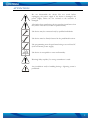
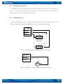
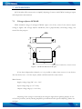
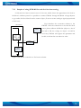
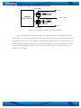
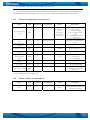
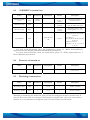
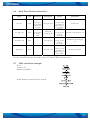
FM3101
(Fleet Management)
USER MANUAL V1.3
Table of Contents
ATTENTION!...............................................................................................................................2
INSTRUCTIONS OF SAFETY ...................................................................................................3
LEGAL NOTICE..........................................................................................................................4
1. Short description ...................................................................................................................5
1.1
About the document ..................................................................................................5
1.2
Acronyms ..................................................................................................................5
1.3
Mounting guidelines .................................................................................................5
2. Package contents...................................................................................................................6
3. Main Features........................................................................................................................7
4. Mechanical features ..............................................................................................................8
5. Connection & pinout...........................................................................................................10
5.1
Socket 2×10 ................................................................................................................10
5.2
PORT 2 & PORT 3 .....................................................................................................11
6. Internal architecture ............................................................................................................12
6.1
Rechargeable battery...................................................................................................13
6.2
1-Wire® devices .........................................................................................................13
7. ACCESSORIES..................................................................................................................14
7.1
Voltage adjuster GCM-001.........................................................................................14
7.1.1
Sample of using GCM-001 for tank fuel level measuring..................................16
7.2
Sample of using two VZO8(4) fuel meters.................................................................17
7.3
Temperature sensor TTJ-101 ......................................................................................18
8. Communication protocols...................................................................................................19
8.1
Power management command set...............................................................................19
8.2
Event counter command set ........................................................................................19
8.3
“1-WIRE®” command set ..........................................................................................20
8.4
Firmware command set...............................................................................................20
8.5
Watchdog command set..............................................................................................20
8.6
Real Time Clock command set ...................................................................................21
8.7
LRC calculation example............................................................................................21
9. Technical support................................................................................................................22
10.
Changes Log Sheet .........................................................................................................23
1
ATTENTION!
Do not disassemble the device. Do not touch before
unplugging the power supply if the device is damaged, the
power supply cables are not isolated or the isolation is
damaged.
All wireless data transferring devices produce interference that
may affect other devices witch are placed nearby.
The device may be connected only by qualified individuals.
The device must be firmly fastened in the predefined location.
The programming must be performed using a second class PC
(with autonomic power supply).
The device is susceptible to water and humidity.
Warning!! May explode, if a wrong accumulator is used.
Any installation and/or handling during a lightning storm is
prohibited.
2
INSTRUCTIONS OF SAFETY
This document contains information on how to operate “FM3101” safely. BY following
these requirements and recommendations you will avoid dangerous situations. You must read
these instructions carefully and follow the strictly before operating the device!
The device uses a 10V...30V DC power supply. The nominal voltage is 24V DC. The
allowed range of voltage is 10V...30V DC, power – not more than 12 W.
To avoid mechanical damage, it is advised to transport the FM3101 device in an impactproof package. Before usage, the device should be placed so that its LED indicators are visible,
which show what status of operation the device is in.
When connecting the connection (2x10) cables to the vehicle, the appropriate jumpers of
the power supply of the vehicle should be disconnected.
Before dismounting the device from the vehicle, the (2x10) connection must be
disconnected.
The device is designed to mount in a zone of limited access, which is inaccessible for the
operator. All related devices must meet the requirements of standard LST EN 60950-1.
The device FM3101 is not designed as a navigational device for boats.
3
LEGAL NOTICE
Copyright © 2006 Teltonika
All rights reserved. Reproduction, transfer, distribution or storage of part or all of the contents
in this document in any form without the prior written permission of Teltonika is prohibited.
Java and all Java based marks are trademarks or registered trademarks of Sun Microsystems,
Inc.
1-Wire is a registered trademark of Dallas Semiconductor.
Other products and company names mentioned herein may be trademarks or trade names of
their respective owners.
4
1. SHORT DESCRIPTION
FM3101 is a terminal with GSM and GPS connectivity, which is able to determine the
object’s coordinates and transfer them via the GSM network. This device is perfectly suitable for
applications where location acquirement of remote objects is needed. It is important to mention that
FM3101 has additional inputs and outputs, which let you control and monitor other devices on
remote objects. 1-Wire® I/O (for Dallas digital thermometer or I-Button reader) is integrated. It
also has a RS232 port (possibility to connect any external device for example a barcode reader, RFID
reader etc.). Apart from that, the device is fully programmable, so you can load a special Java™ IMlet
and perfectly adapt it for your needs.
FM3101 has a rechargeable battery inside and a special controller for power management.
Because of this new feature, GPS/GSM unit can operate for some time without external power
supply. A special power saving algorithm can be implemented in Java™ IMlet and operation time
can be expanded up to 3-5 times.
1.1
About the document
This document contains information about the features, architecture, possibilities,
mechanical characteristics and data transfer types of the FM3101 device.
1.2
Acronyms
PC – Personal Computer.
GPRS – General Packet Radio Service.
GPS – Global Positioning System.
GSM – Global System for Mobile Communications.
SMS – Short Message Service.
RFID – Radio Frequency Identification.
AC/DC – Alternating Current/Direct Current.
1.3
Mounting guidelines
The device is mounted in the predefined location in the object by attaching it using a
two-sided tape and additionally securing using three plastic 300x4 mm straps. If there is no
possibility of mounting the device in the predefined location as written above, alternative
mounting methods may be applied, securing the stable position of the device.
5
2. PACKAGE CONTENTS
The FM3101 device is supplied to the customer in a cardboard box containing all the
equipment that is necessary for operation. The package contains:
1. The FM3101 device.
2. PC <-> FM3101 cable port 2 (For configuring of the module).
3. PC <-> FM3101 cable port 3 (NMEA -> PC).
4. Input and output power supply cable with a 2x10 connection.
5. CD with the Aplicom User Manual, SDK and the User Manual.
6. GPS and GSM antennas.
Supplements:
1. Temperature sensor TTJ-101 (by order).
2. Voltage regulator GCM-100 (by order).
Note: the manufacturer does not supply a SIM card in the package, which is necessary for connection to the GSM
network! SIM card can be obtained from Your local GSM service provider!
If any of the components is not in the package, please contact the manufacturer’s
representative or the vendor. (www.teltoniika.lt)
6
3. MAIN FEATURES
9 Track your remote objects (trucks, cars) quickly and easily.
9 The device supports the following GSM bearers:
o EDGE class 6 (up to 177,4 kbps).
o GPRS class 10 (up to 85,6 kbps).
o HSCSD (up to 43,2 kbps).
o CSD (up to 14,4 kbps).
o SMS (text/data).
o USSD (data).
9 As a lot of connection types are supported, you can choose one according to price, reliability,
speed or ease of use.
9 Dual-band:
o European (and Asian) version - 900 MHz / 1800 MHz.
o American version - 850 MHz / 1900 MHz.
9 The aluminum case of the device is very robust and perfectly suitable for installation into
harsh environment such as cars, trucks, boats or other moving objects.
9 Internal rechargeable battery with charge controller.
9 FM3101 has 3 digital inputs, 3 digital outputs and 3 analogue inputs, which could be used for
performing of various tasks on remote objects, such as monitoring fuel tank level, engine
status, or controlling truck door etc.
9 FM3101 has 1-Wire® I/O protocol integrated for temperature measuring or key
identification.
9 FM 3101 has RS232 port which could be used foe external peripheral data acquisition.
9 FM3101 is an open architecture device, which is fully programmable, so if you want to
perform a very special task, you can adapt the device for your needs by writing your own
Java™ IMlet or asking our technical staff to make it for you. TCP/IP and UDP stacks are
integrated.
9 AutoPIN feature enters the PIN code each time the device is turned on, while SIM card is
still protected with the code.
9 3 LED indicators: “Power”, “Status” and “Navigate”.
9 An advanced solution for a very reasonable price.
7
4. MECHANICAL FEATURES
Figure 1. FM3101 drawing & spec (Dimensions in millimeters, tolerance 0,5 mm)
8
Part name
Navigation LED
Status LED
Power LED
GSM
GPS
Socket 2×10
SIM
PORT 2
PORT 3
Physical specification
LED
LED
LED
GSM antenna connector SMA
GPS antenna connector SMA
Tyco Multi-Lock I/O MK-II C175975
GSM SIM card socket
RJ45 8 pin socket
RJ45 8 pin socket
Technical details
Power supply 10...30 V DC
12W Max
Energy consumption:
GPRS:
400 mA r.m.s Max.,
Nominal:
100 mA r.m.s..
Operation temperature:
-25°C ... +55°C
Storage temperature:
-40°C ... +70°C
Relative humidity 5 ... 95%
When GPS signal is not received, the Navigation LED is blinking as follows:
When GPS signal is received, the Navigation LED is blinking as follows:
When Navigation LED is off, that means a short circuit is GPS antenna or connector.
Power LED means that device is switched on.
9
5. CONNECTION & PINOUT
5.1
Socket 2×10
ACUM 2
“1-Wire®” PWR (+5 V)
“1-Wire®” DATA
“1-Wire®” GND
FC 1
OUT 9
AIN 3
AIN 1
IN 9
IN 7
10
9
8
7
6
5
4
3
2
1
20
19
18
17
16
15
14
13
12
11
ACUM 1
VCC (10÷30)V DC (+)
GND (VCC (10÷30)V DC)(-)
FC 2
OUT 8
OUT 6
AIN 2
GND
IN 8
Figure 2. 2×10 socket pinout
Pin
Nr.
Pin Name
Description
1
2
3
1
2
3
4
5
6
IN 7
IN 9
AIN 1
AIN 3
OUT 9
FC 1
“1-Wire®”
GND
“1-Wire®”
PWR (+5 V)
Digital input, channel 7. *
Digital input, channel 9. *
Analog input, channel 2. Input range: 0-10V DC **
Analog input, channel 3. Input range: 0-10V DC **
Digital output. Channel 9. Open collector output. Max.
500mA.
Fuel Counter (Quick counter digital input, channel 1)
Digital output Channel 7, used for Dallas 1-Wire® devices GND
(purpose: output could be OFF-ON-OFF to reset device)
7
9
10
ACUM 2
11
12
IN 8
GND
+ 5 V output (not only) for Dallas 1-Wire® devices. (max 100mA)
This pin is used connected with pin ACUM 1. Function of those pins is
to disconnect the internal accumulator during shipment or storage.
When ACUM 1 and ACUM 2 are connected, the internal accumulator is
on, while disconnected - the internal accumulator is off.
Digital input, channel 8. *
Ground pin.
10
1
2
3
13
14
15
17
18
AIN 2
OUT 6
OUT 8
GND
-
19
+ (10÷30) V
20
ACUM 1
Analog input, channel 2. Input range: 0-10V DC **
Digital output. Channel 6. Open collector output. Max
500mA.
Digital output. Channel 8. Open collector output. Max
500mA.
Ground pin. (10÷30)V DC ( - )
Power supply for module. Power supply range (10...30) V DC
Energy consumption: GPRS:
400 mA r.m.s Max., Nominal:
100
mA r.m.s..
This pin is used connected with pin ACUM 2. Function of those pins is
to disconnect the internal accumulator during shipment or storage.
When ACUM 1 and ACUM 2 are connected, the internal accumulator is
on; while disconnected, the internal accumulator is off.
* Input is inverted.
** N12i module have input divider of 4.08, that meant if input equals to 10V, then N12i will
receive 2,45V
5.2
PORT 2 & PORT 3
RJ-45 socket
8 7654321
PORT 2
Pin
Nr.
1
2
3
4
5
6
7
8
Description
TXD_GPS
GND
RXD2
TXD2
CTS2
RTS2
PORT 3
Pin
Nr.
1
2
3
4
5
6
7
8
Description
GND
RXD3
TXD3
RTS3
-
¾ Port 2. Connected to N12i port 2. This port can be used as system port
(M2M protocol to configure N12) with cable 1/2 and as GPS NMEA 0183
output with cable PORT 3.
¾ Port 3. Connected to N12i Port 3. This port is controlled by Java application
on the N12i module.
11
6. INTERNAL ARCHITECTURE
APLICOM 12i modem is equipped with J2ME virtual Java™ Machine. This platform can be
used for different user applications. For further documentation of APLICOM 12 modem, please
contact APLICOM corp. (www.aplicom.com ).
FM3101 has special power management schematics and MCU to control power. It can charge
the internal battery and turn on or off all peripheral devices for a desired period of time. PORT3 is
used for APLICOM 12i modem power control. Command set can be found in chapter 8.1.
IN9
TXD3R
CTS3R
IN8
RXD3R
PORT 3
(RS232)
OUT9
OUT8
OUT6
OUT3
Status
LED
OUT5
IN10
AIN2
AIN3
GSM
antenna
N12i
GSM module
RTC
FC 1
WatchDog
OUT4
PORT 2
(RS232)
TXD3R
RXD3R
AIN1
MCU
FC 2
RXD2R
1-WIRE®
TXD2R
1-WIRE®
GND (OUT 7)
CTS2R
RTS2R
Power
management
TXD_GPSR
DC power
supply
PORT 1
(RS232)
GPS
antenna
GPS
receiver
Backup
battery
Figure 3. Internal architecture
* When OUT5 is HIGH, then N12i module is connected to external PORT3, in other case to
MCU.
* Watchdog is monitoring the N12i OUT 4 pin, if it has not changed in 20 min, it restarts N12i. If
after the first restart there is no change, second restart is executed after 1 hour, the same with the
third etc. It is recommended to change the status of N12i OUT4 every half minute.
12
6.1
Rechargeable battery
In FM3101 is used rechargeable battery of 250 mAh capacitance. It is able to supply power if
there is no external power supply, (life time depends on how frequently data is transmitted). Its
lifetime is more than 1000 charge – discharge cycles.
6.2
1-Wire® devices
One of the FM3101 features is realized 1-Wire data protocol, which enables connection of
thermometer (DS1820, DS18S20 and DS18B20) and I-Buttons DS1990A reading.
...
...
...
Figure 5. Digital thermometers DS1820 connection scheme
Figure 6. Digital key “I-Button” DS1990A connection scheme
13
7. ACCESSORIES
JSC Teltonika offers accessories to simplify adjusting of sensors with FM3101 analogue inputs
and temperature measurement.
7.1
Voltage adjuster GCM-001
While maximal voltage of analogue FM3101 input is 2.8 Volts, some of the sensors output
voltage is higher. The voltage adjuster GCM-001, that is proportionally converting voltage, was
created for that purpose.
28
Power
LED
59
Output
socket
Input
socket
1
2
3
4
5
6
7
8
9
10
77
105
Dimensions in millimeters, tolerance ±1mm
Figure 7. GCM-001 dimensions & spec.
It has three independent channels, so it is possible to adjust three sensors in one device.
Also the device has a +5 Volts output, which could be useful for some sensors.
Main features:
Supply voltage (Vpp) DC +10 ÷ 30 V.
Input voltage range (0 ÷ 27 Volts).
Output voltage range (0 ÷ 2.8 Volts).
Adjusting of the voltage is executed by choosing the right divisor (placing jumper on one
of the four positions) and by twisting amplifier’s potentiometer after precise adjusting. (Please see
the fig.8.).
14
+5V OUT
DC/DC
converter
6
1
Vpp
GND
7
2
GND
Adjustable
amplifier
×1 – ×28
Channel 1
OUTPUT 1
8
3
Divisor
×0.31
Divisor
×0.19
Adjustable
amplifier
×1 – ×28
Divisor
×0.1
INPUT 1
Functional scheme
OUTPUT 2
9
OUTPUT 3
10
...
Channel 2
...
Channel 3
Mechanical scheme
(PCB top view)
4
INPUT 2
Divisors pins
(to connect with
jumpers)
5
INPUT 3
Figure 8. GCM-001 functional and mechanical adjusting scheme
15
7.1.1 Sample of using GCM-001 for tank fuel level measuring
A fuel tank level sensor exists in most of the cars, which shows the approximate fuel level in
the driver’s indicator panel. It is possible to connect FM3101 through GCM-001 voltage adjuster
to get online fuel level data from the remote object (if sensor returns analogue signal proportional
to fuel level)
Fig.9 describes the connection scheme to the
Part of the car
FM3101. After the connection to the tank fuel level
+12V
FM3101
sensor please calibrate GCM-001 (adjust so, that if
AIN 1
the tank is full, the voltage on output 1 would be
2.8 Volts). FM3101 will register this parameter and
be able to inform the user about its value.
Input 1
Output 1
GCM-001
Voltage adjuster
TANK FUEL
LEVEL
SENSOR
Figure 9. GCM-001 connection to fuel sensor scheme
16
7.2
Sample of using two VZO8(4) fuel meters
Fuel meter
FC2
Return Flow
Vehicle’s
FUEL CIRCUIT
+12V…+24V
Direct flow
Fuel Filter
FC1
Fuel meter
Figure 10. VZO8(4) fuel meters connection scheme
Fig 10 describes the connection scheme to the FM3101. Here two VZO8(4) meters are
used, where one is mounted on the direct flow pipe and the other on the return flow pipe. Data
from both meters are sent to the FM3101. Then FM3101 calculates FC1-FC2. This difference is
fuel consumption. Filter should be used on the direct flow pipe to prevent any damage caused by
impurities in the liquid. The filter mounted in the meter inlet is only a safety filter and it is too
small to act as a strainer.
17
7.3
Temperature sensor TTJ-101
To simplify the mounting of the thermometer in the object, it is placed on PCB and inserted
into the box. Integrator of the system should solder the FM3101 wires to PCB and place the
sensor wherever he wants to measure the temperature.
Dimensions in millimeters, tolerance ±1mm
Figure 11. TTJ-101 dimensions & spec.
In TTJ-100, Dallas digital thermometer DS1820 is used. It is possible to connect up to five
thermometers parallel and measure the temperature in 5 places in the object (see chapter 6.1.1).
The picture bellow describes pinout of the TTJ-100.
Right row of pins
Left row of pins
Connected
through 100 Ohm
1
to 1 on right row
(FM3101 - 9 pin)
Data (to 1-Wire®
2
Dallas)
(FM3101 - 8 pin)
GND
3
(FM3101 - 7 pin)
Connected to 4
4
on right row.
1
Vpp (+5 Volts DC)
2
Connected to pin 4
on left row
18
8. COMMUNICATION PROTOCOLS
For communication between APLICOM 12i modem, MCU, GPS module and RFID receiver,
the ModBus protocol is applied. All of the possible commands are described in tables below.
8.1
Power management command set
Name
Code
Parameter
Description
Answer
Description
0 – external power supply OK,
battery charged
1 – battery is charging
2 – power supply is from
battery
3 – accumulator discharged
4 – charge error
N12i module and GPS are
switched off for defined time
period.
Get power supply
state
0x06
-
-
1 symbol. - 0,
1, 2, 3, 4
2 symbols –
last charge
time (min)
Enter power save
state
0x07
0-59
Time in minutes
-
Get power supply
voltage
0x09
-
-
0-29000
Power supply voltage in mV*
Get battery voltage
0x0A
-
-
0-10000
Battery voltage in mV
Get battery charge
current
0x0B
-
-
0-1294
Battery charge current in mA
0x0D
-
-
0, 1, 2
0 – normal state
1 – short circuit
2 – not plugged
0x0E
-
-
1 byte
Temperature in 0C
Get status of GPS
antenna power
supply
Temperature of
battery
Battery charge
ON/OFF
0 – Battery charge ON
1 – Battery charge OFF
If module has no external
Power down mode
0x20
voltage supply, switches the
module off.
* - Real voltage on the power supply is higher than the answers of the command 0x09 by 0.7 Volts. It is because of the
protection diode on the power supply pin.
8.2
0x11
0-1
-
-
Description
Answer
Description
Unsigned long
4byte
When MCU gets request -> it
returns FC1-FC2 answer and
resets both counters
Event counter command set
Name
Code
Parameter
Read counter “FC1FC2”
0x17
-
-
19
8.3
“1-WIRE®” command set
Name
Code
Parameter
Calculate existing
sensors
0x14
Sensor
number
Read sensor data
0x15
Sensors initialize
0x16
Get_I-Button
Description
Gets I-Button
ID
0x26
Answer
Description
Number of
sensors, 1
symbol
Temperature, 2
symbols
Number of
sensors;
1 symbol
If the answer is 0xF000, an
error in temperature read
8 bytes
I-Button present:
:01|26|01|id|id|id|id|id|id|c
rc(ib)| lrc
No I-Button:
:01|26|00|00|00|00|00|00|0
0|00| lrc
I-Button read error:
:01|26|11|11|11|11|11|11|1
1|11| lrc
Returns the number of
connected sensors
Calculating sensors, and
attaching ID (0, 1, 2, 3, 4)
For more detail information about the thermometer, please see “Dallas Semiconductors”
digital thermometer DS1820, DS18S20 and DS18B20 specifications.
For more detail information about the thermometer, please see “Dallas Semiconductors” IButton DS1990A specification.
8.4
Firmware command set
Name
Code
Parameter
Get Firmware
0x27
-
8.5
Description
-
Answer
Description
4byte
String “0102” means the
version V1.2
Watchdog command set
Name
Code
Parameter
Description
Answer
Description
Watchdog_enable
0x18
1
1 byte
1
Enables watchdog
Watchdog_disable
0x18
0
1 byte
0
Disable watchdog
Watchdog is monitoring the N12i OUT 4 pin, if it has not changed in 20 min, it restarts N12i. If
after the first restart there is no change, second restart is executed after 1 hour, the same with the
third etc. It is recommended to change the status of N12i OUT4 every half minute.
20
8.6
Real Time Clock command set
Name
Code
Parameter
Description
7 bytes
Set_time
0x22
Set_RTC_CR
0x23
:01|22|ss|m
m|hh|dwdw
|dmdm|mm
|yy|LRC
2 bytes
:01|23|cr1cr
1|cr2cr2|
LRC
Answer
Description
7 bytes
Setting the time
:01|22|ss|mm
|hh|dwdw|d
mdm|mm|yy|
crc(t)|LRS
2 bytes
Setting the
control register
:01|23|cr1cr1
:01|24|cr1cr1
|cr2cr2|
crc(t)|LRC
7 bytes
Read_RTC_CR
0x24
-
Get CR value
Read_RTC
0x25
-
Get time value
Set RTC time
Set RTC Control Register 1/2
|cr2cr2|
crc(t)|LRS
2 bytes
:01|25|ss|mm
|hh|dwdw|d
mdm|mm|yy|
crc(t)|LRC
Read RTC Control Register
1/2
Read time from RTC
CR (Control Register) – RTC (RS5C338A) management registers
For more detail information about RTC, please see “Ricoh” RS5C338A datasheet.
8.7
LRC calculation example
Id: 01
Function: 25
Modbus: 0125(LRC)
Finally Modbus command will be :012538
21
9. TECHNICAL SUPPORT
If you encounter any problems when using our products, please contact our technical support
by writing an e-mail to [email protected] . We will be pleased to help you.
If you are interested in other products from Teltonika, please visit our website
www.teltonika.com, where you will find our newest products.
If you are interested in product pricing or want to order our products with different antennas,
connectors or built-in programs, please contact our sales department by writing an e-mail to
[email protected]
The supervision of the device is undemanding.
22
10.CHANGES LOG SHEET
Nr.
Date
1.
June 8, 2006
New
version
number
1.1
2.
July 11, 2006
1.2
3.
November 24, 2006
1.3
Comments
Corrected pinout, changed figure 2
Safety instructions updated, fig. 4.1 edited.
Updated FM3101 architecture, command set, added
LRC calculation example.
23