1
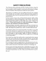
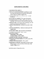
Model 7154
2-Pole High Voltage Scanner Card
Instruction
Contains
Operating
and Servicing
Manual
Information
WARRANTY
Model
7154 2-Pole High Voltage
Scanner Card
instruction Manual
B 1988, Kcithlcy Instruments, Inc.
Test Instrumentation Croup
All rights reserved.
Cleveland, Ohio, U.S.A.
March 1988, First Printing
document Numhcr: 7154-901-01 Rev. A
SAFETY PRECAUTIONS
The following safety precautions should be observed before using this
product and any associated instrumentation. Although some instruments
and accessories would normally be used with non-hazardous voltages,
there are situations where hazardous conditions may be present.
This product is intended for use by qualified personnel who recognize
shock hazards and are familiar with the safety precaution8 required to
avoid possible injury. Read the operating information carefully before using the product.
Exercise extreme caution when a shock hazard is present. Lethal voltage
may be present on cable connector jacks or test fixtures. The American
National Standards Institute (ANSI) states that a shock hazard exists
when voltage levels greater than 30V RMS, 42.4V peak, or 60VDC are
present. A good safety practice is to expect that hazardous voltage is
present in any unknown circuit before measuring.
Before operating an instrument, make pure the line cord is connected to a
properly grounded power receptacle. Inspect the connecting cables, test
leads, and jumpers for possible wear, cracks, or breaks before each use.
For maximum safety, do not touch the product, test cables, or any other
instruments while power is applied to the circuit under test. ALWAYS remove power from the entire test system and discharge any capacitors before: connecting or disconnecting
cables or jumpers, installing
or
removing switching cards, or making internal changes, such as installing
or removing jumpers.
Do not touch any object
side of the circuit under
mcasurcmcnts with dry
capable of withstanding
that could provide a current path to the common
test or power line (earth) ground. Always make
hands while standing on a dry, insulated surface
the voltage being measured.
Do not exceed the maximum signal levels of the instruments and accessories, as defined in the specifications and operating information, and as
shown on the instrument or test fixture rear panel, or switching card.
Do not connect switching cards directly to unlimited power circuits. They
arc intended to be used with impedance limited sources. NEVER connect
switching cards directly to AC main. When connecting sources to switching cards, install protective devices to limit fault current and voltage to
the card.
When fuses are used in a product, replace with same type and rating for
continued protection against fire hazard.
Chassis connections must only be used as shield connections for rneasuring circuits, NOT as safety earth ground conncctionfi.
If you are using a test fixture, keep the lid closed while power is applied
to the device under test. Safe operation requires the use of a lid interlock.
If a @ screw is present on the test fixture,
ground using #18 AWG or larger wire.
connect it to safety earth
The $ symbol on an instrument or accessory indicates that 1OOOV or
more may be present on the terminals. Refer to the product manual for detailed operating information.
Instrumentation
and accessories should not be connected to humans.
Maintenance should be performed by qualified service personnel. Before
performing any maintenance, disconncct the line cord and all test cables.
SPECIFICATIONS
CHANNELS
PER CARD: 10.
CONTACT CONFIGURATION:
Z-pole Form A with
user selectable shield or driven guard. Each pole is
fused using No. 38 AWG magnet wire.
CONNECTOR
maximum.
TYPE: Screw terminals,
RELAY DRIVE
CURRENT:
No. 16 AWG
57mA per relay typical.
MAXIMUM
SIGNAL LEVEL: 1lOOV peak, 0.5A nns
switched, 1.OA rms carry, 1OVA (resistive load only).
CONTACT LIFE: >lO”closures (cold switching);
closures (at maximum signal levels).
CONTACT
life.
RESISTANCE:
CONTACT POTENTIAL:
copper leads.
ACTUATION
CHANNEL
TIME
<2WmQ initial, 2n to rated
<35pV per contact pair with
<2ms, exclusive
ISOLATION:
>5 x 10‘
of mainframe.
>lO’“fl, <lOpF.
INPUT ISOLATION:
Differential:
>lOQ, c50pF.
Common Mode: >lOQ <150pF.
COMMON MODE VOLTAGE:
OPERATING ENVIRONMENT:
at 70% R.H.
STORAGE
ENVIRONMENT:
1lOOV peak.
0’ to 50°C; up to 35°C
-25O to +65OC.
DIMENSIONS,
WEIGHT: 32mm high x 114mm wide x
272mm long (l-l/4 in. x 4-l/2 in. X lo-3/4 in.). Net
weight 0.34kg (12 oz.).
TABLE OF CONTENTS
SECTION
1.1
1.2
1.3
1.4
1.5
1.6
1-
Introduction.
.........................
Warranty Information
.................
Manual Addenda .....................
Safety Symbols and Terms ............
Unpacking and Inspection .............
Specifications ........................
SECTION 2 2.1
2.2
2.3
2.4
2.5
2.6
2.6.1
2.6.2
2.6.3
2.6.4
.......
.......
.......
.......
.......
.......
.:
2
3
3
3
Operation
Introduction ..........................................
Safety Precautions ....................................
Wiring ...............................................
Installation and Removal ..............................
.............................
Operating Considerations
Applications .........................................
Shielded ..........................................
Guarded..
........................................
Driven Guard .....................................
4-Wire .............................................
SECTION 3 3.1
3.2
3.3
3.4
3.5
3.5.1
3.5.2
General Information
Servicing
5
5
5
6
7
11
11
12
12
13
Information
Introduction .........................................
Handling and Cleaning ..............................
Recommended Test Equipment, .......................
Contact Resistance Test ...............................
Isolation Tests .......................................
Channel Isolation ..................................
Input Isolation., ...................................
17
17
18
18
19
20
22
SECTION 4 4.1
4.2
4.3
4.4
4.5
ii
Replaceable
Parts
Introduction...............,,,...........,,..........
Replaceable Parts
Ordering Information
Factory Service
.,.
Component Layout and Schematic Dmgram.,
25
25
26
LIST OF TABLES
SECTION 3 3-l
Recommended
SECTION 4 4-1
Servicing
Information
Test Equipment.
Replaceable
18
Parts
Model 7l54 Replaceable Parts
26
iii/iv
LIST OF ILLUSTRATIONS
SECTION
l-1
1 -
Model 7l54 Simplified
SECTION 2 2-l
2-2
2-3
2-4
2-5
2-6
1
Operation
Servicing
9
1’10
11
12
.l3
...
15
Information
Contact Resistance ...................................
Channel Isolation ....................................
Input Isolation ......................................
SECTION 4 4-l
4-2
Schematic.
Limiting Capacitive Reaction Current .................
Limiting Inductive Reaction Voltage. ..................
Shielded Floating Measurement ......................
Guarded Floating Measurement. .....................
Single-Pole Switch with Switched Guard .............
Source with External Sense or Kelvin Measurement
SECTION 3 3-l
3-2
3-3
General Information
Replaceable
19
21
23
Parts
Model 7154 Component Layout
Model 7l54 Schematic Diagram
27
29
SECTION
1
General Information
1.1 INTRODUCTION
The Model 7154 is a 2.pole high voltage scanner card that switches signal
levels up to llOOV, 0.5A or IOVA peak (lOmA at 1OOOV)for resistive loads
only. Each of the 10 channels on the card consists of a double-pole, normally open (Z-Form A) relay with a user selectable shield or driven
guard connection and a fused input. The output connection and the
input connections have screw terminals with a maximum allowable wire
size of No. 16 AWG. A schematic representation is shown in Figure 1-l.
”
CH. t
I.
Figure
l-l.
Model 7154 Simplified
Schematic
1
Switching is done in less than Zmsec exclusive of the mainframe, and
the specified contact life is >lO’ closures with cold switching and >lO*
closures at maximum signal levels. The relay drive current is 57mAirelay.
The Model i’l54 is field installable in an appropriate Keithley scanner
mainframe (e.g. Model 705 or Model 706). With the isolation between
each channel being greater than 1OYl and less than lOpF, each channel is well insulated from cross channel noise and interference.
1.2 WARRANTY
INFORMATION
Warranty information is stated on the inside front cover of this manual.
If there is a need for service, contact the Keithley representative or
authorized repair facility in your area. Check the back cover for addresses. The service form supplied at the end of the manual should
be used to provide the service facility with information concerning any
difficulty.
1.3 MANUAL
ADDENDA
Product improvements or changes to this manual will be explained on
an addendum included with the manual. It is recommended that this
information be incorporated immediately into the appropriate places
in the manual.
If an additional instruction
manual is required, order the manual
package (Keithley Part Number 7154-901-00). The manual package includes an instruction manual and all pertinent addenda.
2
1.4 SAFETY
SYMBOLS
AND TERMS
The symbol A
on the card denotes that the user should refer to the
operating instructions.
The symbol &
terminals.
denotes that a high voltage may be present on the
The WARNING used in this manual explains danger? that could result
in personal injury or death.
The CAUTION used in this manual explains hazards that could damage
the instrument.
1.5 UNPACKING
AND INSPECTION
The Model 7154 was inspected both electrically and mechanically before
shipment. Upon receiving the Model 7154, unpack all items from the
shipping carton and check for any obvious damage that may have occurred during transit. Report any damage to the shipping agent. Retain and use the original packaging materials in case reshipment is
necessary The following items are shipped with every Model 7154:
Model 7154 Z-Pole High Voltage Scanner Card
Model 7154 Instruction Manual
1.6 SPECIFICATIONS
Detailed specifications
of this manual.
of the Model 7154 precede the Table of Contents
314
SECTION
2
Operation
2.1 INTRODUCTION
This section provides information needed to use the Model 7154 2-Pole
High Voltage Card with the Models 705 and 706 scanner mainframes.
Once the card is installed in the mainframe, refer to the mainframe instruction manual for complete operating instructions.
2.2 SAFETY
PRECAUTIONS
WARNING
User supplied lethal voltages may be present on the PC
board or the connections.
Turn off all Dower and
discharge stored energy in external circuitry before making or breaking connections.
1. Do not exceed the Model ?l54 maximum voltages of -tllOOV peak
terminal to terminal and +llOOV peak any terminal to chassis.
2. Make sure the scanner mainframe is grounded through an earth
grounded receptacle before operation.
3. inspect all test lead connections for wear and defects such as cracks
and exposed wires.
4. Use appropriately rated cables when switching high voltages.
2.3 WIRING
Each channel on the Model il54 card consists of a double-pole. normally open (2.Form A) switching relay. The Model 7154 will switch any
one of the 10 signals (inputs) to one output, or switch one signal to
any one of 10 outputs. See Figure 1-l.
5
NOTE
Because of the high impedance of the board, take special
care when handling and using to prevent degradation of
performance. Handle the board by the edges to avoid contaminating it with dirt, body oil, etc. For cleaning instructions, see paragraph 3.2.
1. Wiring is accomplished by means of terminal strips as shown on the
component layout (see Figure 4-l). Each channel has a HI connection, LO connection, and GUARD connection. Guard is common
to all channels with the jumpers (Wl-WlO) installed. The Model 7154
is shipped with all jumpers installed.
2. Resistance of the relay contacts path is less than 0.2%
3. A common guard surrounds all analog signal paths.
4. Use wires or cables that are rated for greater than 11OOV.The maximum allowable wire size is No. 16 AWG. The minimum wire size
is No. 26 AWG.
5. Route the wires through the rubber clamp pads located at the rear
of the card.
2.4 INSTALLATION
AND REMOVAL
Once the card is wired, insert it card-edge first into the scanner mainframe by aligning it with the grooves in the appropriate slot. Make sure
it is properly seated into the mainframe connector. Push the locking
tabs forward to the center of the card to lock it in.
To remove a card, first turn off the mainframe and all other equipment
connected to the card. Unfasten the locking tabs on the card by pulling the tabs outward. Grasp the end of the card and carefully pull it
out of the mainframe.
2.5 OPERATING
CONSIDERATIONS
Since the Model 7154 is a IO-channel card, set the scanner to the 2-p&z
mode when using the Model 7154 by itself OT when intermixing with
other IO-channel cards. In the 2-pole scanner mode, each scanner channel controls one channel on one IO-channel card.
The 4-p&
mode of operation
will be discussed in Section 2.6
Signal Levels-The maximum signal levels for the Model 7l54 2.Pole
High Voltage Card are IlOOV maximum, 0.5A or 1OVA peak for resistive
loads only. The specified contact life is >lO” closures with cold switching and >lO” closures at maximum signal levels.
WARNING
When switching signals greater than 30V RMS or 42.2V
peak take cere to prevent contact with live circuits which
could cease electrical shock resulting in injury or death.
Cables-Shielded
cables should be used with the Model 7E4 card when
switching above 5OV. The shield should be connected to the circuit LO
or GUARD. This prevents excessive radiation from the cables from interfering with any equipment. The cables must be rated for greater than
11OOV.
Fusible Links-The
Model 7154 scanner card has a fusible link
(SQl-5420) in series with the high and low input side of each channel’s relay. A link opens when the current level on that channel becomes
excessive because of an external circuit misapplication or a relay failure.
The links protect the PC board from damage that is difficult to repair
(e.g. lifted or burned traces on the board).
A repair procedure
for the links follows:
1. Clean out the PC board feedthru
desoldering tool.
holes for the fusible link with a
7
Insert a jumper of No. 38 AWG magnet wire into the holes and solder
in place.
CAUTION
This wire must be taut to maintain
voltage
spacing.
CAUTION
When replacing the fusible links, use only No. 38 AWG
magnet wire. Use of any other wire may cause severe
damage to the PC board.
Check the same channel’s relay contacts for a short or insufficient
input isolation resistance and replace the relay if necessary. See Sections 3 and 4.
Clean the PC board according to the instructions given in paragraph
3.2.
Depending on your application, a current limiting resistor can be used
in place of a fusible link. Each resistor will limit the current flow through
one side (HI or LO) of one channel. The resistors must be of sufficient
power rating to safely dissipate any overload.
Reactive Loads-The Model 7154 is specified for resistive loads only.
Since reactive loads can cause excessive currents and voltages, current
surge limiting (for capacitive loads) and voltage clamping (for inductive loads) are required to prevent damaging the relays and external
circuitry
1. Capacitive Loads - The surge current from a capacitive load must
be less than 0.5A to protect the relays. Figure 2-l shows typical circuits to limit current surges. Also, consider the maximum load of
1OVAwhen determining the current limit. For example, when switching 5OOV,the current must be limited to 20mA (I = lOVA/5OOV) and
the limiting resistor calculation of Figure 2.lA would be:
R = V/l = 500Vi20mA
= 25kQ
2. Inductive Loads Inductive reaction voltage, L(di/dt), must be less
than 11OOV.Typical clamping circuits are shown in Figure 2-2. Also,
consider the maximum load of 1OVA when determining the voltage
limit, For example, when switching 4OmA, the voltage must be
limited to 250V (V = lOVAi40mA) and the clamping resistor calculation of Figure 2.2A would be:
R = V/l = 250Vi40mA
= 62500
A. RESISTOR LIMITED
g-Jqy%y
LOAD
* HIGH RESISTANCE COLD.
LOW RESISTANCE HOT.
FAST THERMAL RECOVERY.
6. THERMISTOR LIMITED
Figure 2-1. Limiting
Capacitive
Reaction
Current
9
f-Ji--#~j
LoAD
A. RESISTOR CLAMPED (AC OR DC VOLTAGES)
H +
0
CD
LOAD
L
B. DK)DE CLAMPED (DC VOLTAGES)
!Y-Jl-jEF)
LoAD
C. ZENER CLAMPED (AC VOLTAGES)
”
a!IN
H
L
c
LOAD
7154
R.
L
CD
D. RESISTORCAPACITOR CLAMPED (AC VOLTAGES)
Figure 2-2. Limiting
Inductive
Reaction
Voltage
2.6 APPLICATIONS
The Model 7154 can monitor high voltages from 10 different devices
under test (DUT), switch a high voltage source to 10 separate DUTs,
or connect multiple DUTs to multiple sources.
2.6.1 Shielded
CAUTION
This application
is one channel at a time. Due to the
possibility of high voltage, be aura to break one connection before connecting
another or the card could be
damaged.
The measurement scheme shown in Figure 2-3 is used to make a shielded floating measurement on up to 10 DUTs with one meter. The guard
traces are used as a shield, so they are connected to the meter’s LO.
If both GUARD pins can not be kept at the same potential, remove the
jumper.
N : 1, Jumper in or OUIdepending on system grounding 9~heme
Figure
2-3. Shielded
Floating
Measurement
11
2.6.2 Guarded
Non-driven guarded measurements are made with the set up shown
in Figure 2-4. The jumper is installed to provide a guard which completely encloses high and low. This guards them from other channels
on the card for improved channel isolation
Figure 2-4. Guarded
2.6.3 Driven
Floating
Measurement
Guard
If multiple sources are switched to a DUT using a driven guard, as
shown in Figure 2-5A, the guard must be switched. The jumper for
each channel in use is removed so that the various sources will not try
to drive other guards. Instrument LO is not switched or is switched
by another card for both Figures 2-5A and 2.58.
LO and GUARD are shorted at both ends of the signal path to allow
for the switched guard. Low for the source(s) and DUT must be a connection made externally.
Figure 2.5B is the same configuration for connecting one source to multiple DUTs. In this case, the jumper is removed to reduce the capacitive
loading on the guard.
Figure 2-5. Single-Pole
Switch
with Switched
Guard
2.6.4 4.Wire
Connecting multiple DUTs to one instrument using either a Kelvin
technique or external sense as with a Source Measure Unit (SMU), requires two cards operating in 4-p& mode. This is shown in Figure 2-6.
HI and Sense HI are switched through one card. The jumper is installed to provide a guard all the way to the DUT. Since this is a driven
guard, it is connected only to the guard of the instrument and not terminated at the DUT.
Lo and Sense LO are switched through the second card. The jumper
is installed to provide shielding for these lines. The shield on the cabling should cover as much of the signal lines as possible, and should
be terminated only at the instrument. Shields are typically at circuit
low or earth.
This configuration combines sense and Kelvin configurations so that
guard on the card is driven for the High leads and is a shield for the
Low leads.
14
Figure 2-6. Source with External Sense or Kelvin Measurement
15116
SECTION
3
Servicing Information
3.1 INTRODUCTlON
This section describes tests for verifying
7l54. The tests include:
l
l
the performance
of the Model
Functionality
test Measuring contact resistance to check for open
or shorted relays or bad connections.
Specification tests - Two isolation tests measuring leakage currents
to check for a contaminated board and possibly bad relays.
Perform these tests in an environment within the specified operating
temperature range (0” to 35°C up to 70% RH) of the scanner card.
WARNING
Do not perform the procedures In thls section unless
you are a qualifted service person. Some of the procedures may expose you to potenttally lethal voltages
(>3OV RMS) that could result in personal Injury or death
if normal safety precautions
are not observed.
Recommended maintenance includes inspection of the scanner card
and the card edge connector to ensure good electrical contact. The
Model 7154 does not require calibration.
3.2 HANDLING
AND CLEANING
Because of the high impedance of the board, take special care when
handling and using to prevent degradation of performance. Handle the
board by the edges to avoid contaminating it with dirt, body oil, etc.
17
To clean the board, spray on an uncontaminated
solvent, such as
Freon@ TMS or TE and clean with cotton swabs or a soft brush. After
the solvent has been applied and is still liquid, blow-dry the board with
dry nitrogen gas.
3.3 RECOMMENDED
TEST EQUIPMENT
Table 3-l lists recommended test equipment for performance verification. Other test equipment may be substituted if specifications equal
or exceed those stated
NOTE
The Model 617 electrometer has an internal 1OOVsource.
If the Model 617 is used, its internal voltage can be used
in place of the Model 230 Voltage Source.
Table 3-1. Recommended
Test Equipment
Description
Model
Keithley
Keithley
Keithley
Keithley
Keithley
Scanner Mainframe
Extender Card
DMM
Voltage Source
Electrometer
3.4 CONTACT
RESISTANCE
705 or 706
7061
196
230
614 or 617
TEST
This test measures the resistance of each relay contact in an opened
and closed state.
1. Set up the equipment as shown in Figure 3-l. Short the HI terminal
to the LO terminal of each channel. Attach two copper wires to the
output HI and LO terminals.
2. Zero the Model 196 with the Kelvin test leads shorted together.
18
3. Set the channel mainframe to the channel mode, channel 1, and the
step mode. Close channel 1 from the scanner front panel. The reading
on the Model 196 should indicate a short circuit (less than 0.20).
4. Open channel 1 from the scanner front panel. The reading on the
Model 196 should indicate an open circuit (>300Mfl).
5. Repeat steps 3 and 4 for the remaining channels on the card.
MODEL
7154 IN SCANNER
MAINFRAME
KELVIN TEST LEADS -
Figure
3.5 ISOLATION
3-1. Contact
Resistance
TESTS
The two isolation tests measure leakage currents for calculating leakage
resistances on the Model 7154. With the Model 7061 Universal Adpater
Card, these tests can be performed faster.
19
3.51
Channel
Isolation
This test measures the leakage current between two channels.
1. Set up the equipment as shown in Figure 3-2.
2. Set the scanner to channel 1 and the step mode. Program channel
1 open and the other channels as closed.
CAUTION
Make sure the channel under teat is OPEN. Failure to
do this can csuse damage to the Instrument.
3. Set the electrometer to amps and zero check. Program the Model
230 to output 1OOV.Take the electrometer out of zero check.
4. The electrometer should read less than 10-8AA.(Due to the capacitance
of the circuit, the offset current may be high until the circuit
capacitance is charged up. Wait until the readings settle out.)
5. Using Ohm’s law, calculate the channel isolation (the leakage
resistance between two channels). For example:
R = E/l = 100V/10-8A = lOLoO
NOTE
With the Model 617 electrometer in V/l mode, the resistance
is calculated automatically.
6. Put the Model 230 in standby mode and set the electrometer to zero.
7. Repeat steps 2 through 6 for the remaining channels.
20
.I
MODEL
r-
7154
CHANNEL
UNDER TEST
HI
Lo
IN SCANNER
G
MAINFRAME
HI
1
OUTPUT
Lo
ELECTROMETER
1OOV SOURCE
Figure 3-2. Channel
Isolation
21
3.5.2 Input
Isolation
This test measures the leakage current between a channel’s HI and LO
terminals.
1. Set up the equipment as shown in Figure 3-3.
2. Set the scanner to channel 1 and the step mode. Close channel 1
and open all other channels.
3. Set the electrometer to amps and zero check. Program the Model
230 to output 1OOV.Take the electrometer out of zero check.
4. The electmmeter should read less than 10.‘A. (Due to the capacitance
of the circuit, the offset current may be high until the circuit
capacitance is charged up. Wait until the readings settle out.)
5. Using Ohm’s law, calculate the input isolation (leakage resistance)
for this channel. For example:
R = E/l = IOOVilO-‘A = IO’Q.
NOTE
With the Model 617 electrometer in VII mode, the resistance
is calculated automatically.
6. Put the Model 230 in standby mode and set the electrometer to zero.
7. Repeat steps 2 through 6 for the remaining channels.
NOTE
For all other channels, the channel under test should be
closed and all other channels open.
22
MODEL
7154 IN SCANNER
HI
CHANNEL
UNDERTEST
G
MAINFRAME
lo
AMPS
1OOV SOURCE
Figure 3-3. Input lsolatlon
23/24
SECTION
4
Replaceable Parts
4.1 INTRODUCTION
This section contains replacement parts information,
a component
layout, and a schematic diagram for the Model 7154.
4.2 REPLACEABLE
PARTS
Table 4-I lists parts alphanumerically
tions.
4.3 ORDERING
in the order of their circuit designa-
INFORMATION
To place an order or to obtain information about replacement parts, contact your Keithley representative or the factory. See the back cover for
addresses. When ordering, include the following information:
l
l
l
l
l
Model number
Serial number
Part description
Circuit description (if applicable)
Keithley part number
4.4 FACTORY
SERVICE
If the scanner card is to be returned to Keithley Instruments
perform the following:
for repair,
1. Photocopy and complete the service form at the back of this manual
and include it with the card.
25
2. Carefully pack the card in the original packing carton.
3. Write A’ITENTION REPAIR DEPARTMENT on the shipping
label.
Note that it is not necessary to return the scanner mainframe with the
card.
4.5 COMPONENT
LAYOUT
AND SCHEMATIC
DIAGRAM
Figure 4-l shows a component layout of the Model 7154. Figure 4-2
shows the schematic diagram of the Model 7I54.
Table 4-I. Model 7154 Replaceable
Parts
Description
Keithley
Part No.
Cl
c2
C3Cl2
Capacitor, 1OpE 25V, Aluminum
Capacitor, O.l@, 5OV, Ceramic
Capacitor, O.Ol& 5w, Ceramic
c-314-10
C-365-.1
C-365-.01
El
Ferrite Bead
CT-9
15. 16
17
Connector
Connector
a-464-4
cs-4643
K&K10
Relay, 2.Form A
RL-118
SQlSQ20
Fusible Link, No. 38 AWG Magnet Wire
-
Circuit
Desig.
I
13
7055-303-1s
7055.308
26
Figure
4-1. Model 7154 Component
Layout
27128
Service Form
Keithley Instruments, Inc.
Test Instrumentation Croup
28775 Aurora Road
Cleveland,
Ohio 4413~
Printed
in the U.S.A.