1
STP 11-25L13-SM-TG
Soldier’s Manual and Trainer’s Guide
MOS 25L
CABLE SYSTEMS
INSTALLER-MAINTAINER
SKILL LEVELS 1, 2, AND 3
August 2008
DISTRIBUTION RESTRICTION: Approved for public release; distribution is
unlimited.
HEADQUARTERS
DEPARTMENT OF THE ARMY
This publication is available at Army Knowledge
Online (AKO) (www.us.army.mil) and General Dennis
J. Reimer Training and Doctrine Digital Library at
(http://www.train.army.mil)
*
SOLDIER TRAINING
PUBLICATION
No. 11-25L13-SM-TG
HEADQUARTERS
DEPARTMENT OF THE ARMY
Washington, DC, 12 August 2008
SOLDIER'S MANUAL and TRAINER'S GUIDE
MOS 25L
MOS 25L CABLE SYSTEMS INSTALLER-MAINTAINER
Skill Levels 1, 2, and 3
CONTENTS
Page
PREFACE .................................................................................................................................................... vi
Chapter 1. INTRODUCTION ..................................................................................................................... 1-1
1-1. General........................................................................................................................... 1-1
1-2. Training Equipment ........................................................................................................ 1-1
1-3. Battle-Focused Training ................................................................................................. 1-4
1-4. Task Summary Format................................................................................................... 1-5
1-5. Training Execution.......................................................................................................... 1-6
1-6. Training Assessment......................................................................................................1-7
1-7. NCO Self-Development and the Soldier’s Manual ......................................................... 1-8
1-8. Training Support............................................................................................................. 1-9
1-9. Feedback........................................................................................................................ 1-9
Chapter 2. TRAINER’S GUIDE................................................................................................................. 2-1
2-1. General........................................................................................................................... 2-1
2-2. Subject Area Codes .......................................................................................................2-2
2-3. Critical Task List ............................................................................................................. 2-3
Chapter 3. MOS/SKILL LEVEL TASKS .................................................................................................. 3-1
Skill Level 1
Subject Area 1: NAVIGATE
113-610-2044 Navigate Using the AN/PSN-11 ................................................................................ 3-1
Subject Area 2: CABLE AND EQUIPMENT
113-588-2002 Perform Cable Marking Procedures .......................................................................... 3-3
113-588-2003 Install Connectors on Copper Cable ......................................................................... 3-4
113-588-2004 Perform a Splice on a Plastic Sheath, Plastic Insulated Cable ................................. 3-9
DISTRIBUTION RESTRICTION: Approved for public release; distribution is unlimited.
*This publication supersedes STP 11-25L13-SM-TG, dated 15 March 2005.
i
STP 11-25L13-SM-TG
113-588-2003 Install Connectors on Copper Cable ......................................................................... 3-4
113-588-2004 Perform a Splice on a Plastic Sheath, Plastic Insulated Cable ................................. 3-9
113-588-2005 Install AC/DC Power Source for Communications Equipment...............................3-11
113-588-2006 Install Cable/Wire Systems......................................................................................3-20
113-588-2010 Recover Cable/Wire System ..................................................................................3-21
113-632-4001 Install Commercial Fiber Optic Terminators/Connectors .......................................3-22
113-632-4002 Splice Commercial Fiber Optic Cable .....................................................................3-24
113-574-3006 Perform Unit Level Maintenance (ULM) on Telephone Test Set TS-3647/G..........3-25
113-574-3010 Perform Unit Level Maintenance (ULM) on Electrical Cable Test Set
AN/GTM-12 ...........................................................................................................3-27
113-574-3011 Perform Unit Level Maintenance (ULM) on Test Set TS-4117()/G .........................3-28
113-588-0005 Troubleshoot Telephone Cable WD-1( )/TT or WF-16/U ........................................3-30
113-588-0016 Troubleshoot CX-11230A/G Cable System.............................................................3-32
113-588-0018 Troubleshoot 26-Pair Cable CX-4566/G ................................................................3-34
113-588-1002 Set Poles .................................................................................................................3-37
113-588-1074 Install Aerial Cable Splicing Equipment..................................................................3-39
113-588-1075 Install Underground Cable Splicing Equipment.......................................................3-41
113-588-1106 Install a Connector on a Stranded Flexible Coaxial Cable......................................3-42
113-588-1107 Install Underground Cable System..........................................................................3-44
113-588-1108 Install a CAD-6 Buried Distribution Terminal...........................................................3-46
113-588-3005 Perform Unit Level Maintenance (ULM) on Reel Unit RL-31()................................3-48
113-588-4022 Repair Plastic-Sheathed Cable ...............................................................................3-49
113-588-8001 Perform Pole Rescue Operation .............................................................................3-51
113-588-9008 Make a Coaxial Cable Splice ..................................................................................3-53
113-632-5001 Troubleshoot Fiber Optic Transmission System (FOTS) Cable System.................3-55
113-632-5002 Troubleshoot Fiber Optic Cable ..............................................................................3-57
Subject Area 3: MULTIPLEXERS
113-606-0105 Troubleshoot Multiplexer TD-1233(P)/TTC or Multiplexer-Combiner TD1234(P)/TTC .........................................................................................................3-59
113-606-0106 Troubleshoot Line Termination Unit (LTU) CV-4180( ) ...........................................3-60
113-606-1001 Install Multiplexer TD-1233(P)/TTC or Multiplexer-Combiner TD-1234(P)/TTC .....3-62
113-606-1002 Install Line Termination Unit (LTU) CV-4180( ) .......................................................3-63
113-606-3090 Perform Unit Level Maintenance (ULM) on Multiplexer TD-1233(P)/TTC OR
MULTIPLEXER-COMBINER TD-1234(P)/TTC ....................................................3-65
113-606-3091 Perform Unit Level Maintenance (ULM) on Line Termination Unit (LTU) CV4180( )...................................................................................................................3-66
Subject Area 4: TELEPHONE SETS
113-600-1001 Install Secure Digital Telephone STU-III/STE .........................................................3-68
113-628-1001 Install Voice Over Internet Protocol (VoIP) Telephone ...........................................3-69
113-600-0011 Troubleshoot KY-68.................................................................................................3-70
113-600-1012 Install Telephone Set TA-312/PT ............................................................................3-71
113-600-1016 Install Digital Nonsecure Voice Terminal (DNVT) ...................................................3-73
113-600-1017 Install Telephone Set TA-838/TT ............................................................................3-75
113-600-1022 Install KY-68 ...........................................................................................................3-76
113-600-3017 Perform Unit Level Maintenance (ULM) on Telephone Set TA-312/PT..................3-77
113-600-3020 Perform Unit Level Maintenance (ULM) on Telephone Set TA-838/TT ..................3-79
ii
12 August 2008
STP 11-25L13-SM-TG
Subject Area 5: TELEPHONE MAINTENANCE TRUCK
113-588-0007 Perform Preventive Maintenance Checks and Services (PMCS) on
Telephone Maintenance Truck .............................................................................3-81
113-588-2007 Operate Telephone Maintenance Truck..................................................................3-82
Subject Area 6: LAN/WAN SUBSTATION
113-583-1001 Perform Soldering Techniques................................................................................3-83
113-583-1002 Install Cable Rack and Wire Way............................................................................3-86
113-583-1003 Install Distribution Frames .......................................................................................3-91
113-583-1004 Install Anchoring Devices ........................................................................................3-94
113-583-1007 Interpret Engineering Installation Packet (EIP) .......................................................3-97
113-583-1008 Perform Marking Site Layout.................................................................................3-100
113-583-1009 Install Local Area Network/Wide Area Network (LAN/WAN) Substation
Distribution System .............................................................................................3-104
113-583-2001 Operate Hand and Power Tools............................................................................3-106
113-588-0001 Troubleshoot Local Area Network/Wide Area Network (LAN/WAN)
Substation Distribution System ...........................................................................3-108
113-588-0020 Determine Cable Depth Using the 2273 Advanced Cable and Fault Locator.......3-110
113-588-0021 Locate Cable Faults Using a Time Domain Reflectometer (TDR) Test Set..........3-112
113-588-6008 Maintain a Communications Systems Installation Record (CSIR) ........................3-113
Subject Area 7: COMSEC
113-609-1002 Install Trunk Encryption Device.............................................................................3-114
113-609-2002 Operate Trunk Encryption Device .........................................................................3-115
113-609-3001 Maintain Trunk Encryption Device.........................................................................3-116
Subject Area 8: CONDUIT
113-583-1010 Install Conduit........................................................................................................3-117
Skill Level 2
Subject Area 9: CABLE AND EQUIPMENT SUPERVISION
113-588-7005 Supervise Recovery of Cable/Wire Systems.........................................................3-126
113-588-7006 Supervise Troubleshooting of Cable/Wire Systems..............................................3-127
113-588-7012 Supervise Installation of Cable/Wire Systems ......................................................3-128
113-632-9014 Supervise Splicing of Commercial Fiber Optic Cable ...........................................3-129
113-574-7014 Supervise Unit Level Maintenance (ULM) on Test Sets .......................................3-130
113-606-7026 Supervise Installation of Multiplexers ....................................................................3-131
113-606-7027 Supervise Troubleshooting of Multiplexers ...........................................................3-132
113-606-7028 Supervise Unit Level Maintenance (ULM) on Multiplexers ...................................3-133
Subject Area 10: TELEPHONE SETS SUPERVISION
113-600-7042 Supervise Installation of KY-68 .............................................................................3-134
113-600-7043 Supervise Troubleshooting of KY-68.....................................................................3-135
Subject Area 11: LAN/WAN SUBSTATION SUPERVISION
113-588-7003 Supervise Installation of Local Area Network/Wide Area Network
(LAN/WAN) Substation Distribution System .......................................................3-137
113-588-7007 Supervise Troubleshooting of Local Area Network/Wide Area Network
(LAN/WAN) Substation Distribution System .......................................................3-139
Skill Level 3
Subject Area 12: CABLE AND EQUIPMENT INSPECTION
113-588-7001 Inspect Installation of AC/DC Power Source for Communications Equipment .....3-140
113-588-7002 Supervise Basic Safety in Cable Systems Installation ..........................................3-146
12 August 2008
iii
STP 11-25L13-SM-TG
113-588-7008 Inspect Installation of Cable/Wire Systems ...........................................................3-147
113-588-7009 Inspect Recovery of Cable/Wire Systems .............................................................3-149
113-588-7011 Inspect Troubleshooting of Cable/Wire Systems ..................................................3-151
113-632-9009 Inspect Operation of Fiber Optic Cable Test Set ..................................................3-152
113-632-9012 Inspect Splicing of Fiber Optic Cable Assembly (FOCA) CX-13295( )/G .............3-153
113-574-9001 Inspect Unit Level Maintenance (ULM) on Test Sets...........................................3-154
113-588-5007 Plan a Telephone Cable Line ................................................................................3-155
113-588-6001 Inspect Existing Cable Lines .................................................................................3-156
113-588-6007 Prepare a Detailed Cable Route Map ...................................................................3-158
113-588-7075 Inspect Poles .........................................................................................................3-159
Subject Area 13: TELEPHONE MAINTENANCE TRUCK INSPECTION
113-588-7108 Inspect Preventive Maintenance Checks and Services (PMCS) of Telephone
Maintenance Truck .............................................................................................3-160
Subject Area 14: TELEPHONE SETS INSPECTION
113-600-7045 Inspect Installation of KY-68..................................................................................3-161
113-600-7046 Inspect Troubleshooting of KY-68 .........................................................................3-162
Subject Area 15: MULTIPLEXER INSPECTION
113-606-7029 Inspect Installation of Multiplexers ........................................................................3-163
113-606-7030 Inspect Troubleshooting of Multiplexers................................................................3-164
113-606-7031 Inspect Unit Level Maintenance (ULM) on Multiplexers........................................3-165
Subject Area 16: LAN/WAN SUBSTATION INSPECTION
113-613-4003 Verify Engineering Installation Package (EIP) .....................................................3-166
113-632-7002 Inspect Installation of Local Area Network/Wide Area Network (LAN/WAN)
Substation Distribution System ...........................................................................3-168
113-632-9007 Inspect Installation of Commercial Fiber Optic Cable Terminators/Connectors ...3-170
113-632-9010 Inspect Repair of Fiber Optic Cable Assembly (FOCA) CX-13295( )/G ...............3-172
113-632-9011 Inspect Splicing of Commercial Fiber Optic Cable................................................3-173
113-632-9013 Inspect Troubleshooting of Local Area Network/Wide Area Network
(LAN/WAN) Substation Distribution System .......................................................3-174
Subject Area 17: COMPUTER TECHNOLOGY
113-580-7128 Supervise the Configuration of an AIS to Operate on a Network..........................3-176
Subject Area 18: NAVIGATION
113-610-7005 Implement Land Navigation Skills Using Global Positioning Systems..................3-177
Subject Area 19: MOBILE SUBSCRIBER EQUIPMENT
113-611-6006 Lead Restoration of Transmission Link Within a Network.....................................3-179
113-593-1040 Establish Site Layout for Transmission Systems ..................................................3-180
Chapter 4. DUTY POSITION TASKS ...................................................................................................... 4-1
Subject Area 20: ANTENNA INSTALLATION
113-588-1086 Install Pressurized Cable System.............................................................................. 4-1
113-596-1024 Install Parabolic Antenna........................................................................................... 4-4
113-596-1027 Install AB-216/U Tower.............................................................................................. 4-6
113-596-1040 Install Pressurized Transmission Lines ..................................................................... 4-9
113-596-1080 Install Self-Support Tower .......................................................................................4-10
113-596-1081 Remove Self-Support Tower ...................................................................................4-12
113-596-1082 Install Spira-Cone High Frequency (HF) Antenna...................................................4-13
113-596-1083 Remove Spira Cone High Frequency (HF) Antenna...............................................4-15
iv
12 August 2008
STP 11-25L13-SM-TG
113-596-1084 Remove AB-216/U Tower........................................................................................4-16
113-596-1086 Remove Broadband Dipole High Frequency (HF) Antenna ....................................4-18
113-596-3010 Maintain Rotatable Log Periodic Antenna ...............................................................4-19
113-596-3011 Maintain Delta-Matched Doublet Antenna...............................................................4-22
113-596-3012 Maintain Fixed Log Periodic Antenna......................................................................4-24
113-596-3014 Maintain Rhombic Antenna .....................................................................................4-27
113-596-3015 Maintain Parabolic Antenna ....................................................................................4-30
113-596-3016 Maintain Yagi Antenna ............................................................................................4-32
113-596-3018 Maintain AB-216/U Tower .......................................................................................4-34
113-596-3021 Maintain Self-Support Tower...................................................................................4-36
113-596-3047 Maintain Spira-Cone High Frequency (HF) Antenna .............................................4-38
113-596-3049 Maintain Broadband Dipole High Frequency (HF) Antenna....................................4-40
113-596-4005 Maintain Coaxial Cable for Antenna Systems.........................................................4-41
113-596-4008 Maintain Pressurization Equipment.........................................................................4-43
APPENDIX A ............................................................................................................................................ A-1
APPENDIX B ............................................................................................................................................ B-1
Glossary
......................................................................................................... Glossary-1
References
......................................................................................................References-1
12 August 2008
v
Preface
This publication is for skill levels 1, 2, and 3 Soldiers holding military occupational specialty (MOS) 25L
and for trainers and first-line supervisors. It contains standardized training objectives, in the form of task
summaries, to train and evaluate Soldiers on critical tasks that support unit missions during wartime.
Trainers and first-line supervisors should ensure Soldiers holding MOS 25L skill levels 1, 2, and 3 have
access to this publication. It should be made available in the Soldier’s work area, unit learning center,
and unit libraries.
This publication applies to the Active Army, the Army National Guard (ARNG)/Army National Guard of the
United States (ARNGUS), and the United States Army Reserve (USAR).
The proponent for this publication is the Signal School. Send comments and recommendations on
Department of the Army (DA) Form 2028 (Recommended Changes to Publications and Blank Forms)
directly to Commander, US Army Signal Center and Fort Gordon, ATTN: ATZH-DTM-I, Fort Gordon,
Georgia 30905-5074.
This publication is available on the General Dennis J. Reimer Training and Doctrine Library for viewing
and downloading. The World Wide Web (WWW) address is http://www.train.army.mil/.
Unless this manual states otherwise, masculine pronouns do not refer exclusively to men.
NOTE: Information contained in this publication is subject to change as new equipment is
added to the Army inventory and revisions in policy and doctrine are made.
vi
12 August 2008
Chapter 1
Introduction
1-1. GENERAL. The Soldier training publication (STP) identifies the individual military occupational
specialty (MOS) and training requirements for Soldiers in various specialties. Another source of STP task
data is the General Dennis J. Reimer Training and Doctrine Digital Library at http://www.train.army.mil/.
Commanders, trainers, and Soldiers should use the STP to plan, conduct, and evaluate individual training
in units. The STP is the primary MOS reference to support the self-development and training of every
Soldier in the unit. It is used with the Soldier’s Manual of Common Tasks, Army Training and Evaluation
Programs (ARTEPs), and Field Manual (FM) 7-0, Training the Force, to establish effective training plans
and programs that integrate Soldier, leader, and collective tasks. This chapter explains how to use the
STP in establishing an effective individual training program. It includes doctrinal principles and
implications outlined in FM 7-0. Based on these guidelines, commanders and unit trainers must tailor the
information to meet the requirements for their specific unit.
1-2. TRAINING EQUIPMENT. Every Soldier, noncommissioned officer (NCO), warrant officer, and officer
has one primary mission—to be trained and ready to fight and win our nation's wars. Success in battle
does not happen by accident; it is a direct result of tough, realistic, and challenging training.
a.
Operational Environment
(1) Commanders and leaders at all levels must conduct training with respect to a wide variety of
operational missions across the full spectrum of operations; these operations may include combined
arms, joint, multinational, and interagency considerations, and span the entire breadth of terrain and
environmental possibilities. Commanders must strive to set the daily training conditions as closely as
possible to those expected for actual operations.
(2) The operational missions of the Army include not only war, but also military operations other
than war (MOOTW). Operations may be conducted as major combat operations, a small-scale
contingency, or a peacetime military engagement. Offensive and defensive operations normally dominate
military operations in war along with some small-scale contingencies. Stability operations and support
operations dominate in MOOTW. Commanders at all echelons may combine different types of operations
simultaneously and sequentially to accomplish missions in war and MOOTW. These missions require
training since future conflict will likely involve a mix of combat and MOOTW, often concurrently. The
range of possible missions complicates training. Army forces cannot train for every possible mission; they
train for war and prepare for specific missions as time and circumstances permit.
(3) Our forces today use a train-alert-deploy sequence. We cannot count on the time or opportunity
to correct or make up training deficiencies after deployment. Maintaining forces that are ready now,
places increased emphasis on training and the priority of training. This concept is a key link between
operational and training doctrine.
(4) Units train to be ready for war based on the requirements of a precise and specific mission; in
the process they develop a foundation of combat skills that can be refined based on the requirements of
the assigned mission. Upon alert, commanders assess and refine from this foundation of skills. In the
train-alert-deploy process, commanders use whatever time the alert cycle provides to continue refinement
of mission-focused training. Training continues during time available between alert notification and
deployment, between deployment and employment, and even during employment as units adapt to the
specific battlefield environment and assimilate combat replacements.
12 August 2008
1-1
STP 11-25L13-SM-TG
b.
How the Army Trains the Army
(1) Training is a team effort and the entire Army—Department of the Army (DA), major Army
commands (MACOMs), the institutional training base, units, the combat training centers (CTCs), each
individual Soldier and the civilian workforce—has a role that contributes to force readiness. DA and
MACOMs are responsible for resourcing the Army to train. The Institutional Army, including schools,
training centers, and NCO academies, for example, train Soldiers and leaders to take their place in units
in the Army by teaching the doctrine and tactics, techniques, and procedures (TTP). Units, leaders, and
individuals train to standard on their assigned critical individual tasks. The unit trains first as an organic
unit and then as an integrated component of a team. Before the unit can be trained to function as a team,
each Soldier must be trained to perform their individual supporting tasks to standard. Operational
deployments and major training opportunities, such as major training exercises, CTCs, and ARTEPs
provide rigorous, realistic, and stressful training and operational experience under actual or simulated
combat and operational conditions to enhance unit readiness and produce bold, innovative leaders. The
result of this Army-wide team effort is a training and leader development system that is unrivaled in the
world. Effective training produces the force—Soldiers, leaders, and units—that can successfully execute
any assigned mission.
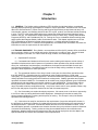
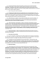
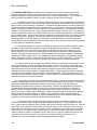
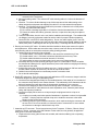
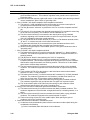
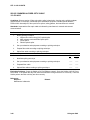
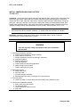
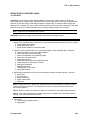
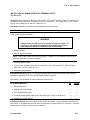
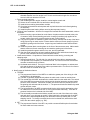
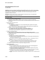
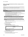
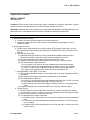
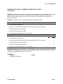
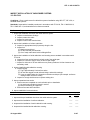
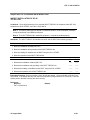
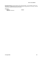
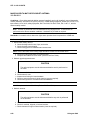
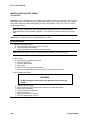
(2) The Army Training and Leader Development Model (Figure 1-1) centers on developing trained
and ready units led by competent and confident leaders. The model depicts an important dynamic that
creates a lifelong learning process. The three core domains that shape the critical learning experiences
throughout a Soldiers and leaders time span are the operational, institutional, and self-development
domains. Together, these domains interact using feedback and assessment from various sources and
methods to maximize warfighting readiness. Each domain has specific, measurable actions that must
occur to develop our leaders.
Figure 1-1. Army Training and Leader Development Model
(3) The operational domain includes home station training, CTC rotations, and joint training
exercises and deployments that satisfy national objectives. Each of these actions provides foundational
experiences for Soldier, leader, and unit development. The institutional domain focuses on educating and
training Soldiers and leaders on the key knowledge, skills, and attributes required to operate in any
environment. It includes individual, unit and joint schools, and advanced education. The selfdevelopment domain, both structured and informal, focuses on taking those actions necessary to reduce
or eliminate the gap between operational and institutional experiences.
1-2
12 August 2008
STP 11-25L13-SM-TG
(4) Throughout this lifelong learning and experience process, there is formal and informal
assessment and feedback of performance to prepare leaders and Soldiers for their next level of
responsibility. Assessment is the method used to determine the proficiency and potential of leaders
against a known standard. Feedback must be clear, formative guidance directly related to the outcome of
training events measured against standards.
c.
Leader Training and Leader Development.
(1) Competent and confident leaders are a prerequisite to the successful training of units. It is
important to understand that leader training and leader development are integral parts of unit readiness.
Leaders are inherently Soldiers first and should be technically and tactically proficient in basic Soldier
skills. They are also adaptive, capable of sensing their environment, adjusting the plan when appropriate,
and properly applying the proficiency acquired through training.
(2) Leader training is an expansion of these skills that qualifies them to lead other Soldiers. As
such, doctrine and principles of training require the same level of attention of senior commanders.
Leader training occurs in the Institutional Army, the unit, the CTCs, and through self-development.
Leader training is just one portion of leader development.
(3) Leader development is the deliberate, continuous, sequential, and progressive process,
grounded in Army values, that grows Soldiers and civilians into competent and confident leaders capable
of decisive action. Leader development is achieved through the lifelong synthesis of the knowledge,
skills, and experiences gained through institutional training and education, organizational training,
operational experience, and self-development. Commanders play the key roll in leader development that
ideally produces tactically and technically competent, confident, and adaptive leaders who act with
boldness and initiative in dynamic, complex situations to execute mission-type orders achieving the
commander’s intent.
d. Training Responsibility. Soldier and leader training and development continue in the unit.
Using the institutional foundation, training in organizations and units focuses and hones individual and
team skills and knowledge.
(1) Commander Responsibility.
(a) The unit commander is responsible for the wartime readiness of all elements in the formation.
The commander is, therefore, the primary trainer of the organization and is responsible for ensuring that
all training is conducted in accordance with (IAW) the STP to the Army standard.
(b) Commanders ensure STP standards are met during all training. If a Soldier fails to meet
established standards for identified MOS tasks, the Soldier must retrain until the tasks are performed to
standard. Training to standard on MOS tasks is more important than completion of a unit-training event
such as an ARTEP. The objective is to focus on sustaining MOS proficiency—this is the critical factor
commanders must adhere to when training individual Soldiers units.
(2) NCO Responsibility.
(a) A great strength of the US Army is its professional NCO Corps who takes pride in being
responsible for the individual training of Soldiers, crews, and small teams. The NCO support channel
parallels and complements the chain of command. It is a channel of communication and supervision from
the Command Sergeant Major (CSM) to the First Sergeants (1SGs) and then to other NCOs and enlisted
personnel. NCOs train Soldiers to the non-negotiable standards published in STPs. Commanders
delegate authority to NCOs in the support channel as the primary trainers of individual, crew, and small
team training. Commanders hold NCOs responsible for conducting standards-based, performanceoriented, battle-focused training and providing feedback on individual, crew, and team proficiency.
Commanders define responsibilities and authority of their NCOs to their staffs and subordinates.
12 August 2008
1-3
STP 11-25L13-SM-TG
(b) NCOs continue the Soldierization process of newly assigned enlisted Soldiers, and begin their
professional development. NCOs are responsible for conducting standards-based, performance-oriented,
battle-focused training. They identify specific individual, crew, and small team tasks that support the
unit’s collective mission essential tasks; plan, prepare, rehearse, and execute training; and evaluate
training and conduct after action reviews (AARs) to provide feedback to the commander on individual,
crew, and small team proficiency. Senior NCOs coach junior NCOs to master a wide range of individual
tasks.
(3) Soldier Responsibility. Each Soldier is responsible for performing individual tasks identified
by the first-line supervisor based on the unit’s mission essential task list (METL). Soldiers must perform
tasks to the standards included in the task summary. If Soldiers have questions about tasks or which
tasks in this manual they must perform, they are responsible for asking their first-line supervisor for
clarification, assistance, and guidance. First-line supervisors know how to perform each task or can direct
Soldiers to appropriate training materials, including current FMs, technical manuals (TMs), and Army
regulations (ARs). Soldiers are responsible for using these materials to maintain performance. They are
also responsible for maintaining standard performance levels of all Soldier's Manual of Common Tasks at
their current skill level and below. Periodically, Soldiers should ask their supervisor or another Soldier to
check their performance to ensure that they can perform the tasks.
1-3. BATTLE-FOCUSED TRAINING. Battle focus is a concept used to derive peacetime training
requirements from assigned and anticipated missions. The priority of training in units is to train to
standard on the wartime mission. Battle focus guides the planning, preparation, execution, and
assessment of each organization's training program to ensure its members train as they are going to fight.
Battle focus is critical throughout the entire training process and is used by commanders to allocate
resources for training based on wartime and operational mission requirements. Battle focus enables
commanders and staffs at all echelons to structure a training program that copes with non-mission-related
requirements while focusing on mission essential training activities. It is recognized that a unit cannot
attain proficiency to standard on every task whether due to time or other resource constraints. However,
unit commanders can achieve a successful training program by consciously focusing on a reduced
number of METL tasks that are essential to mission accomplishment.
a. Linkage between METL and STP. A critical aspect of the battle focus concept is to understand
the responsibility for and the linkage between the collective mission essential tasks and the individual
tasks that support them. For example, the commander and the CSM/1SG must jointly coordinate the
collective mission essential tasks and supporting individual tasks on which the unit will concentrate its
efforts during a given period. This task hierarchy is provided in the task database at the Reimer Digital
Library. The CSM/1SG must select the specific individual tasks that support each collective task to be
trained. Although NCOs have the primary role in training and sustaining individual Soldier skills, officers
at every echelon remain responsible for training to established standards during both individual and
collective training. Battle focus is applied to all missions across the full spectrum of operations.
b. Relationship of STPs to Battle-focused Training. The two key components of any STP are the
Soldier's manual (SM) and trainer’s guide (TG). Each gives leaders important information to help
implement the battle-focused training process. The trainer’s guide relates Soldier and leader tasks in the
MOS and skill level to duty positions and equipment. It states where the task is trained, how often
training should occur to sustain proficiency, and who in the unit should be trained. As leaders assess and
plan training, they should rely on the trainer’s guide to help identify training needs.
(1) Leaders conduct and evaluate training based on Army-wide training objectives and on the task
standards published in the Soldier's manual task summaries or in the Reimer Digital Library. The task
summaries ensure that trainers in every unit and location define task standards the same way and
trainers evaluate all Soldiers to the same standards.
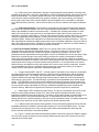
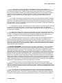
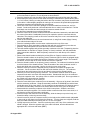
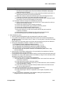
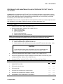
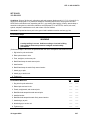
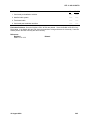
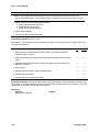
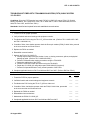
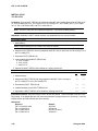
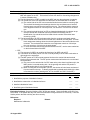
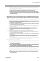
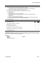
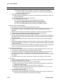
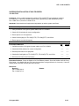
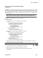
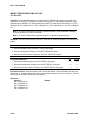
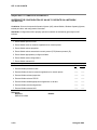
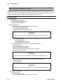
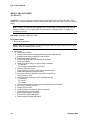
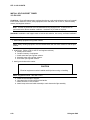
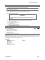
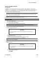
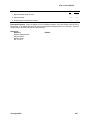
(2) Figure 1-2 shows how battle-focused training relates to the trainer’s guide and Soldier's manual.
The left column shows the steps involved in training Soldiers and the right column shows how the STP
supports each of these steps.
1-4
12 August 2008
STP 11-25L13-SM-TG
BATTLE-FOCUS PROCESS
STP SUPPORT PROCESS
Select supporting Soldier tasks
Use TG to relate tasks to METL
Conduct training assessment
Use TG to define what Soldier tasks to assess
Determine training objectives
Use TG to set objectives
Determine strategy; plan for training
Use TG to relate Soldier tasks to strategy
Conduct pre-execution checks
Use SM task summary as source for task performance
Execute training; conduct AAR
Use SM task summary as source for task performance
Evaluate training against established standards
Use SM task summary as standard for evaluation
Figure 1-2. Relationship of Battle-Focused Training and STP
1-4. TASK SUMMARY FORMAT. Task summaries outline the wartime performance requirements of
each critical task in the SM. They provide the Soldier and the trainer with the information necessary to
prepare, conduct, and evaluate critical task training. As a minimum, task summaries include information
the Soldier must know and the skills that he must perform to standards for each task. The format of the
task summaries included in this SM is as follows:
a. Task Number. A 10-digit number identifies each task or skill. This task number, along with the
task title, must be included in any correspondence pertaining to the task.
b.
Task Title. The task title identifies the action to be performed.
c. Conditions. The task conditions identify all the equipment, tools, references, job aids, and
supporting personnel that the Soldier needs to use to perform the task in wartime. This section identifies
any environmental conditions that can alter task performance, such as visibility, temperature, or wind.
This section also identifies any specific cues or events that trigger task performance, such as a chemical
attack or identification of a threat vehicle.
d. Standards. The task standards describe how well and to what level the task must be performed
under wartime conditions. Standards are typically described in terms of accuracy, completeness, and
speed.
e. Training and Evaluation. The training evaluation section identifies specific actions, known as
performance steps, which the Soldier must do to successfully complete the task. These actions are in the
evaluation guide section of the task summary and are listed in a GO/NO GO format for easy evaluation.
For some tasks, the training and evaluation section may also include detailed training information in a
training information outline and an evaluation preparation section. The evaluation preparation section
indicates necessary modifications to task performance in order to train and evaluate a task that cannot be
trained to the wartime conditions. It may also include special training and evaluation preparation
instructions to accommodate these modifications, and any instructions that should be given to the Soldier
before evaluation.
f.
References. This section identifies references that provide more detailed and thorough
explanations of task performance requirements than those given in the task summary description.
g. Warnings. Warnings alert users to the possibility of immediate personal injury or damage to
equipment.
h. Notes. Notes provide a supportive explanation or hint that relates to the performance
standards.
12 August 2008
1-5
STP 11-25L13-SM-TG
1-5. TRAINING EXECUTION. All good training, regardless of the specific collective, leader, and
individual tasks being executed, must comply with certain common requirements. These include
adequate preparation, effective presentation and practice, and thorough evaluation. The execution of
training includes preparation for training, conduct of training, and recovery from training.
a. Preparation for Training. Formal near-term planning for training culminates with the publication
of the unit-training schedule. Informal planning, detailed coordination, and preparation for executing the
training continue until the training is performed. Commanders and other trainers use training meetings to
assign responsibility for preparation of all scheduled training. Preparation for training includes selecting
tasks to be trained, planning the conduct of the training, training the trainers, reconnaissance of the site,
issuing the training execution plan, and conducting rehearsals and pre-execution checks. Pre-execution
checks are preliminary actions commanders and trainers use to identify responsibility for these and other
training support tasks. They are used to monitor preparation activities and to follow up to ensure planned
training is conducted to standard. Pre-execution checks are a critical portion of any training meeting.
During preparation for training, battalion and company commanders identify and eliminate potential
training distracters that develop within their own organizations. They also stress personnel accountability
to ensure maximum attendance at training.
(1) Subordinate leaders, as a result of the bottom-up feed from internal training meetings, identify
and select the individual tasks necessary to support the identified training objectives. Commanders
develop the tentative plan to include requirements for preparatory training, concurrent training, and
training resources. At a minimum, the training plan should include confirmation of training areas and
locations, training ammunition allocations, training simulations and simulators availability, transportation
requirements, Soldier support items, a risk management analysis, assignment of responsibility for the
training, designation of trainers responsible for approved training, and final coordination. The time and
other necessary resources for retraining must also be an integral part of the original training plan.
(2) Leaders, trainers, and evaluators are identified, trained to standard, and rehearsed prior to the
conduct of the training. Leaders and trainers are coached on how to train, given time to prepare, and
rehearsed so that training will be challenging and doctrinally correct. Commanders ensure that trainers
and evaluators are not only tactically and technically competent on their training tasks, but also
understand how the training relates to the organization's METL. Properly prepared trainers, evaluators,
and leaders project confidence and enthusiasm to those being trained. Trainer and leader training is a
critical event in the preparation phase of training. These individuals must demonstrate proficiency on the
selected tasks prior to the conduct of training.
(3) Commanders, with their subordinate leaders and trainers, conduct site reconnaissance, identify
additional training support requirements, and refine and issue the training execution plan. The training
plan should identify all those elements necessary to ensure the conduct of training to standard.
Rehearsals are essential to the execution of good training. Realistic, standards-based, performanceoriented training requires rehearsals for trainers, support personnel, and evaluators. Preparing for
training in Reserve Component (RC) organizations can require complex pre-execution checks. RC
trainers must often conduct detailed coordination to obtain equipment, training support system products,
and ammunition from distant locations. In addition, RC pre-execution checks may be required to
coordinate Active Component assistance from the numbered Armies in the continental United States
(CONUSA), training support divisions, and directed training affiliations.
b. Conduct of Training. Ideally, training is executed using the crawl-walk-run approach. This
allows and promotes an objective, standards-based approach to training. Training starts at the basic
level. Crawl events are relatively simple to conduct and require minimum support from the unit. After the
crawl stage, training becomes incrementally more difficult, requiring more resources from the unit and
home station, and increasing the level of realism. At the run stage, the level of difficulty for the training
event intensifies. Run stage training requires optimum resources and ideally approaches the level of
realism expected in combat. Progression from the walk to the run stage for a particular task may occur
during a one-day training exercise or may require a succession of training periods over time.
Achievement of the Army standard determines progression between stages.
1-6
12 August 2008
STP 11-25L13-SM-TG
(1) In crawl-walk-run training, the tasks and the standards remain the same; however, the
conditions under which they are trained change. Commanders may change the conditions, for example,
by increasing the difficulty of the conditions under which the task is being performed, increasing the
tempo of the task training, increasing the number of tasks being trained, or by increasing the number of
personnel involved in the training. Whichever approach is used, it is important that all leaders and
Soldiers involved understand in which stage they are currently training and understand the Army
standard.
(2) An AAR is immediately conducted and may result in the need for additional training. Any task
that was not conducted to standard should be retrained. Retraining should be conducted at the earliest
opportunity. Commanders should program time and other resources for retraining as an integral part of
their training plan. Training is incomplete until the task is trained to standard. Soldiers will remember the
standard enforced, not the one discussed.
c. Recovery from Training. The recovery process is an extension of training, and once completed,
it signifies the end of the training event. At a minimum, recovery includes conduct of maintenance
training, turn-in of training support items, and the conduct of AARs that review the overall effectiveness of
the training just completed.
(1) Maintenance training is the conduct of post-operations preventive maintenance checks and
services (PMCS), accountability of organizational and individual equipment, and final inspections. Class
IV, Class V, Training Aids Devices Simulators and Simulations (TADSS) and other support items are
maintained, accounted for, and turned-in and training sites and facilities are closed out.
(2) AARs conducted during recovery focus on collective, leader, and individual task performance,
and on the planning, preparation, and conduct of the training just completed. Unit AARs focus on
individual and collective task performance, and identify shortcomings and the training required to correct
deficiencies. AARs with leaders focus on tactical judgment. These AARs contribute to leader learning
and provide opportunities for leader development. AARs with trainers and evaluators provide additional
opportunities for leader development.
1-6. TRAINING ASSESSMENT. Assessment is the commander's responsibility. It is the commander's
judgment of the organization's ability to accomplish its wartime operational mission. Assessment is a
continuous process that includes evaluating individual training, conducting an organizational assessment,
and preparing a training assessment. The commander uses his experience, feedback from training
evaluations, and other evaluations and reports to arrive at his assessment. Assessment is both the end
and the beginning of the training management process. Training assessment is more than just training
evaluation, and encompasses a wide variety of inputs. Assessments include such diverse systems as
training, force integration, logistics, and personnel, and provide the link between the unit's performance
and the Army standard. Evaluation of training is, however, a major component of assessment. Training
evaluations provide the commander with feedback on the demonstrated training proficiency of Soldiers,
leaders, battle staffs, and units. Commanders cannot personally observe all training in their organization
and, therefore, gather feedback from their senior staff officers and NCOs.
a. Evaluation of Training. Training evaluations are a critical component of any training
assessment. Evaluation measures the demonstrated ability of Soldiers, commanders, leaders, battle
staffs, and units against the Army standard. Evaluation of training is integral to standards-based training
and is the cornerstone of leader training and leader development. STPs describe standards that must be
met for each Soldier task.
(1) All training must be evaluated to measure performance levels against the established Army
standard. The evaluation can be as fundamental as an informal, internal evaluation performed by the
leader conducting the training. Evaluation is conducted specifically to enable the individual undergoing
the training to know whether the training standard has been achieved. Commanders must establish a
12 August 2008
1-7
STP 11-25L13-SM-TG
climate that encourages candid and accurate feedback for the purpose of developing leaders and trained
Soldiers.
(2) Evaluation of training is not a test; it is not used to find reasons to punish leaders and Soldiers.
Evaluation tells Soldiers whether or not they achieved the Army standard and, therefore, assists them in
determining the overall effectiveness of their training plans. Evaluation produces disciplined Soldiers,
leaders, and units. Training without evaluation is a waste of time and resources.
(3) Leaders use evaluations as an opportunity to coach and mentor Soldiers. A key element in
developing leaders is immediate, positive feedback that coaches and leads subordinate leaders to
achieve the Army standard. This is a tested and proven path to develop competent, confident adaptive
leaders.
b. Evaluators. Commanders must plan for formal evaluation and must ensure the evaluators are
trained. These evaluators must also be trained as facilitators to conduct AARs that elicit maximum
participation from those being trained. External evaluators will be certified in the tasks they are evaluating
and normally will not be dual-hatted as a participant in the training being executed.
c. Role of Commanders and Leaders. Commanders ensure that evaluations take place at each
echelon in the organization. Commanders use this feedback to teach, coach, and mentor their
subordinates. They ensure that every training event is evaluated as part of training execution and that
every trainer conducts evaluations. Commanders use evaluations to focus command attention by
requiring evaluation of specific mission essential and battle tasks. They also take advantage of
evaluation information to develop appropriate lessons learned for distribution throughout their commands.
d. AAR. The AAR, whether formal or informal, provides feedback for all training. It is a structured
review process that allows participating Soldiers, leaders, and units to discover for themselves what
happened during the training, why it happened, and how it can be done better. The AAR is a professional
discussion that requires the active participation of those being trained. FM 7-0 provides detailed
instructions for conducting an AAR and detailed guidance on coaching and critiquing during training.
1-7. NCO SELF-DEVELOPMENT AND THE SOLDIER’S MANUAL.
a. Self-development is one of the key components of the leader development program. It is a
planned progressive and sequential program followed by leaders to enhance and sustain their military
competencies. It consists of individual study, research, professional reading, practice, and selfassessment. Under the self-development concept, the NCO, as an Army professional, has the
responsibility to remain current in all phases of the MOS. The SM is the primary source for the NCO to
use in maintaining MOS proficiency.
b. Another important resource for NCO self-development is the Army Correspondence Course
Program (ACCP). Soldiers can access the ACCP online at http://www.atsc.army.mil/accp/aipdnew.asp.
c. General Dennis J. Reimer Training and Doctrine Digital Library is an additional resource for
NCO self-development. This electronic library is the single repository of approved Army training and
doctrine information. Soldiers can access the library online at http://www.train.army.mil/.
`
d. Unit learning centers are valuable resources for planning self-development programs. They can
help access enlisted career maps, training support products, and extension training materials, such as
FMs and TMs. It is the Soldier’s responsibility to use these materials to maintain performance.
1-8
12 August 2008
STP 11-25L13-SM-TG
1-8. TRAINING SUPPORT. This manual includes the following appendixes and information that
provide additional training support information.
(a) Appendix A, DA Form 5164-R (Hands-on Evaluation). This appendix contains the instructions
for using DA Form 5164-R and a completed sample form for NCOs to use during evaluation of Soldiers’
manual tasks.
(b) Appendix B, DA Form 5165-R (Field Expedient Squad Book). This appendix contains the
instructions for using DA Form 5165-R and a completed sample form for NCOs to use during evaluation
of Soldiers’ manual tasks.
(c) Glossary. The glossary is a single comprehensive list of acronyms, abbreviations, definitions,
and letter symbols.
(d) References. This section contains two lists of references, required and related, which support
training of all tasks in this SM. Required references are listed in the conditions statement and are
required for the Soldier to do the task. Related references are materials that provide more detailed
information and a more thorough explanation of task performance.
1-9. FEEDACK. Recommendations for improvement of this STP are requested. Feedback will help to
ensure that this STP answers the training needs of units in the field.
12 August 2008
1-9
This page intentionally left blank.
Chapter 2
Trainer's Guide
2-1. GENERAL. The MOS Training Plan (MTP) identifies the essential components of a unit-training
plan for individual training. Units have different training needs and requirements based on differences in
environment, location, equipment, dispersion, and similar factors. Therefore, the MTP should be used as
a guide for conducting unit training and not a rigid standard. The MTP shows the relationship of an MOS
skill level between duty position and critical tasks. These critical tasks are grouped by task commonality
into subject areas.
The MTP’s Subject Area Codes list subject area numbers and titles used throughout the MTP. These
subject areas are used to define the training requirements for each duty position within an MOS.
The Duty Position Training Requirements table identifies the total training requirement for each duty
position within an MOS and provides a recommendation for cross training and train-up/merger training.
• Duty Position column. This column lists the duty positions of the MOS, by skill level, which have
different training requirements.
• Subject Area column. This column lists, by numerical key, the subject areas a Soldier must be
proficient in to perform in that duty position.
• Cross Train column. This column lists the recommended duty position for which Soldiers should
be cross-trained.
• Train-up/Merger column. This column lists the corresponding duty position for the next higher
skill level or MOSC the Soldier will merge into on promotion.
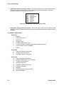
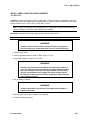
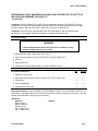
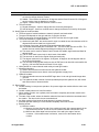
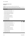
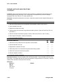
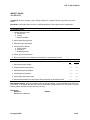
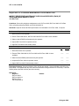
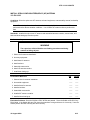
The Critical Task List table lists, by general subject areas, the critical tasks to be trained in an MOS and
the type of training required (resident, integration, or sustainment).
• Subject Area column. This column lists the subject area number and title.
• Task Number column. This column lists the task numbers for all tasks included in the subject
area.
• Title column. This column lists the task title for each task in the subject area.
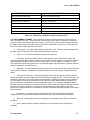
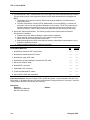
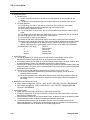
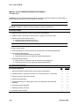
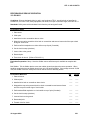
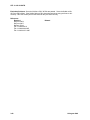
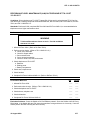
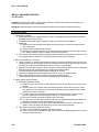
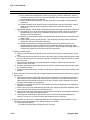
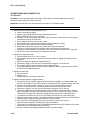
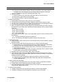
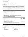
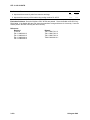
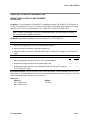
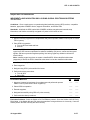
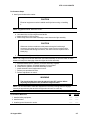
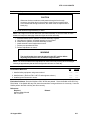
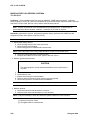
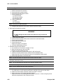
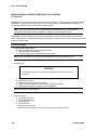
• Training Location column. This column identifies the training location where the task is first
trained to Soldier training publications standards. If the task is first trained to standard in the unit,
the word “Unit” will be in this column. If the task is first trained to standard in the training base, it
will identify, by brevity code (ANCOC, BNCOC, etc.), the resident course where the task was
taught. Figure 2-1 contains a list of training locations and their corresponding brevity codes.
UNIT
AIT
BNCOC
ANCOC
ASI
Trained in the Unit
Advanced Individual Training
Basic NCO Course
Advanced NCO Course
Additional Skill Identifier
Figure 2-1. Training Locations
12 August 2008
2-1
STP 11-25L13-SM-TG
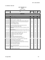
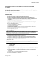
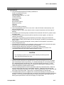
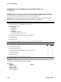
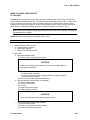
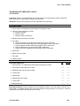
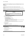
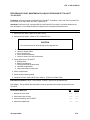
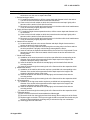
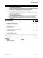
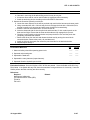
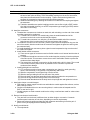
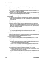
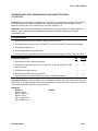
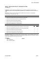
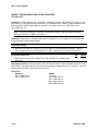
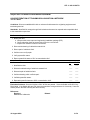
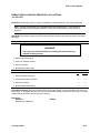
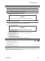
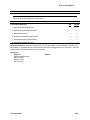
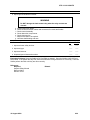
• Sustainment Training Frequency Column. This column indicates the recommended frequency
at which the tasks should be trained to ensure Soldiers maintain task proficiency. Figure 2-2
identifies the frequency codes used in this column.
BA
AN
SA
QT
MO
BW
WK
-
Biannually
Annually
Semiannually
Quarterly
Monthly
Biweekly
Weekly
Figure 2-2. Sustainment Training Frequency Codes
• Sustainment Training Skill Level Column. This column lists the skill levels of the MOS for which
Soldiers must receive sustainment training to ensure they maintain proficiency to Soldier’s manual
standards.
2-2. SUBJECT AREA CODES.
Skill Level 1
1
Navigate
2
Cable and Equipment
3
Multiplexers
4
Telephone Sets
5
Telephone Maintenance Truck
6
Local Area Network (LAN)/Wide Area Network (WAN) Substation
7
Communications Security (COMSEC)
8
Conduit
Skill Level 2
9
Cable and Equipment Supervision
10
Telephone Sets Supervision
11
LAN/WAN Substation Supervision
Skill Level 3
12
Cable and Equipment Inspection
13
Telephone Maintenance Truck Inspection
14
Telephone Sets Inspection
15
Multiplexer Inspection
16
LAN/WAN Substation Inspection
17
Computer Technology
18
Navigation
19
Mobile Subscriber Equipment (MSE)
20
Antenna Installation
2-2
12 August 2008
STP 11-25L13-SM-TG
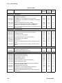
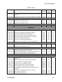
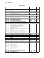
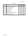
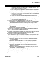
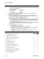
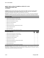
2-3. CRITICAL TASK LIST.
MOS TRAINING PLAN
25L13
CRITICAL TASKS
Task Number
Title
Training
Location
Sust
Tng
Freq
Sust
Tng SL
AIT
SA
1-3
Skill Level 1
Subject Area 1. Navigate
113-610-2044
Navigate Using the AN/PSN-11
Subject Area 2. Cable and Equipment
113-588-2002
Perform Cable Marking Procedures
AIT
AN
1-3
113-588-2003
Install Connectors on Copper Cable
AIT
AN
1-3
113-588-2004
Perform a Splice on a Plastic Sheath, Plastic Insulated Cable
AIT
AN
1-3
113-588-2005
Install AC/DC Power Source for Communications Equipment
UNIT
AN
1-3
113-588-2006
Install Cable/Wire Systems
AIT
SA
1-3
113-588-2010
Recover Cable/Wire System
AIT
SA
1-3
113-632-4001
Install Commercial Fiber Optic Terminators/Connectors
AIT
AN
1-3
113-632-4002
Splice Commercial Fiber Optic Cable
AIT
SA
1-3
113-574-3006
Perform Unit Level Maintenance (ULM) on Telephone Test Set
TS-3647/G
AIT
AN
1-3
113-574-3010
Perform Unit Level Maintenance (ULM) on Electrical Cable Test
Set AN/GTM-12
AIT
SA
1-3
113-574-3011
Perform Unit Level Maintenance (ULM) on Test Set TS-4117()/G
AIT
SA
1-3
113-588-0005
Troubleshoot Telephone Cable WD-1( )/TT or WF-16/U
UNIT
SA
1-3
113-588-0016
Troubleshoot CX-11230A/G Cable System
AIT
SA
1-3
113-588-0018
Troubleshoot 26-Pair Cable CX-4566/G
AIT
SA
1-3
113-588-1002
Set Poles
113-588-1074
Install Aerial Cable Splicing Equipment
UNIT
AN
1-3
AIT
AN
1-3
113-588-1075
Install Underground Cable Splicing Equipment
AIT
AN
1-3
113-588-1106
Install a Connector on a Stranded Flexible Coaxial Cable
AIT
AN
1-3
113-588-1107
Install Underground Cable System
AIT
AN
1-3
113-588-1108
Install a CAD-6 Buried Distribution Terminal
AIT
AN
1-3
113-588-3005
Perform Unit Level Maintenance (ULM) on Reel Unit RL-31()
AIT
SA
1-3
113-588-4022
Repair Plastic-Sheathed Cable
AIT
AN
1-3
113-588-8001
Perform Pole Rescue Operation
UNIT
AN
1-3
113-588-9008
Make a Coaxial Cable Splice
AIT
SA
1-3
113-632-5001
Troubleshoot Fiber Optic Transmission System (FOTS) Cable
System
AIT
SA
1-3
113-632-5002
Troubleshoot Fiber Optic Cable
AIT
SA
1-3
12 August 2008
2-3
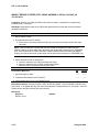
STP 11-25L13-SM-TG
CRITICAL TASKS
Task Number
Title
Training
Location
Sust
Tng
Freq
Sust
Tng SL
AIT
SA
1-3
UNIT
SA
1-3
AIT
SA
1-3
Subject Area 3. Multiplexers
113-606-0105
Troubleshoot Multiplexer TD-1233(P)/TTC or MultiplexerCombiner TD-1234(P)/TTC
113-606-0106
Troubleshoot Line Termination Unit (LTU) CV-4180( )
113-606-1001
Install Multiplexer TD-1233(P)/TTC or Multiplexer-Combiner TD1234(P)/TTC
113-606-1002
Install Line Termination Unit (LTU) CV-4180( )
UNIT
SA
1-3
113-606-3090
Perform Unit Level Maintenance (ULM) on Multiplexer TD1233(P)/TTC or Multiplexer-Combiner TD-1234(P)/TTC
UNIT
SA
1-3
113-606-3091
Perform Unit Level Maintenance (ULM) on Line Termination Unit
(LTU) CV-4180( )
UNIT
SA
1-3
Subject Area 4. Telephone Sets
113-600-1001
Install Secure Digital Telephone STU-III/STE
UNIT
SA
1-3
113-628-1001
Install Voice Over Internet Protocol (VoIP) Telephone
UNIT
SA
1-3
113-600-0011
Troubleshoot KY-68
113-600-1012
Install Telephone Set TA-312/PT
113-600-1016
113-600-1017
AIT
AN
1-3
UNIT
SA
1-3
Install Digital Nonsecure Voice Terminal (DNVT)
AIT
SA
1-3
Install Telephone Set TA-838/TT
AIT
SA
1-3
113-600-1022
Install KY-68
AIT
QT
1-3
113-600-3017
Perform Unit Level Maintenance (ULM) on Telephone Set TA312/PT
UNIT
QT
1-3
113-600-3020
Perform Unit Level Maintenance (ULM) on Telephone Set TA838/TT
AIT
SA
1-3
Subject Area 5. Telephone Maintenance Truck
113-588-0007
Perform Preventive Maintenance Checks and Services (PMCS)
on Telephone Maintenance Truck
UNIT
AN
1-3
113-588-2007
Operate Telephone Maintenance Truck
UNIT
SA
1-3
Subject Area 6. LAN/WAN Substation
113-583-1001
Perform Soldering Techniques
UNIT
AN
1-3
113-583-1002
Install Cable Rack and Wire Way
UNIT
AN
1-3
113-583-1003
Install Distribution Frames
UNIT
AN
1-3
113-583-1004
Install Anchoring Devices
UNIT
AN
1-3
113-583-1007
Interpret Engineering Installation Package (EIP)
UNIT
SA
1-3
113-583-1008
Perform Marking Site Layout
AIT
AN
1-3
113-583-1009
Install Local Area Network/Wide Area Network (LAN/WAN)
Substation Distribution System
AIT
SA
1-3
113-583-2001
Operate Hand and Power Tools
UNIT
AN
1-3
113-588-0001
Troubleshoot Local Area Network/Wide Area Network
(LAN/WAN) Substation Distribution System
AIT
SA
1-3
113-588-0020
Determine Cable Depth Using the 2273 Advanced Cable and
Fault Locator
AIT
AN
1-3
2-4
12 August 2008
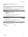
STP 11-25L13-SM-TG
CRITICAL TASKS
Task Number
Title
Training
Location
Sust
Tng SL
AIT
Sust
Tng
Freq
AN
113-588-0021
Locate Cable Faults Using a Time Domain Reflectometer (TDR)
Test Set
113-588-6008
Maintain a Communications Systems Installation Record (CSIR)
UNIT
SA
1-3
1-3
Subject Area 7. COMSEC
113-609-1002
Install Trunk Encryption Device
UNIT
SA
1-3
113-609-2002
Operate Trunk Encryption Device
UNIT
SA
1-3
113-609-3001
Maintain Trunk Encryption Device
UNIT
SA
1-3
UNIT
AN
1-3
Subject Area 8. Conduit
113-583-1010
Install Conduit
Skill Level 2
Subject Area 9. Cable and Equipment Supervision
113-588-7005
Supervise Recovery of Cable/Wire Systems
UNIT
SA
2-3
113-588-7006
Supervise Troubleshooting of Cable/Wire Systems
UNIT
SA
2-3
113-588-7012
Supervise Installation of Cable/Wire Systems
UNIT
SA
2-3
113-632-9014
Supervise Splicing of Commercial Fiber Optic Cable
UNIT
SA
2-3
113-574-7014
Supervise Unit Level Maintenance (ULM) on Test Sets
UNIT
AN
2-3
113-606-7026
Supervise Installation of Multiplexers
UNIT
SA
2-3
113-606-7027
Supervise Troubleshooting of Multiplexers
UNIT
SA
2-3
113-606-7028
Supervise Unit Level Maintenance (ULM) on Multiplexers
UNIT
SA
2-3
Subject Area 10. Telephone Sets Supervision
113-600-7042
Supervise Installation of KY-68
UNIT
SA
2-3
113-600-7043
Supervise Troubleshooting of KY-68
UNIT
SA
2-3
Subject Area 11. LAN/WAN Substation Supervision
113-588-7003
Supervise Installation of Local Area Network/Wide Area Network
(LAN/WAN) Substation Distribution System
UNIT
SA
2-3
113-588-7007
Supervise Troubleshooting of Local Area Network/Wide Area
Network (LAN/WAN) Substation Distribution System
UNIT
SA
2-3
Skill Level 3
Subject Area 12. Cable and Equipment Inspection
113-588-7001
Inspect Installation of AC/DC Power Source for Communications
Equipment
BNCOC
AN
3
113-588-7002
Supervise Basic Safety in Cable Systems Installation
BNCOC
AN
3
113-588-7008
Inspect Installation of Cable/Wire Systems
BNCOC
SA
3
113-588-7009
Inspect Recovery of Cable/Wire Systems
BNCOC
SA
3
113-588-7011
Inspect Troubleshooting of Cable/Wire Systems
BNCOC
SA
3
113-632-9009
Inspect Operation of Fiber Optic Cable Test Set
BNCOC
SA
3
113-632-9012
Inspect Splicing of Fiber Optic Cable Assembly (FOCA) CX13295( )/G
BNCOC
SA
3
113-574-9001
Inspect Unit Level Maintenance (ULM) on Test Sets
BNCOC
AN
3
113-588-5007
Plan a Telephone Cable Line
BNCOC
AN
3
113-588-6001
Inspect Existing Cable Lines
BNCOC
AN
3
12 August 2008
2-5
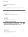
STP 11-25L13-SM-TG
CRITICAL TASKS
Task Number
Title
113-588-6007
Prepare a Detailed Cable Route Map
113-588-7075
Inspect Poles
Training
Location
Sust
Tng SL
BNCOC
Sust
Tng
Freq
SA
UNIT
SA
3
UNIT
AN
3
3
Subject Area 13. Telephone Maintenance Truck Inspection
113-588-7108
Inspect Preventive Maintenance Checks and Services (PMCS)
of Telephone Maintenance Truck
Subject Area 14. Telephone Sets Inspection
113-600-7045
Inspect Installation of KY-68
ANCOC
SA
3
113-600-7046
Inspect Troubleshooting of KY-68
BNCOC
SA
3
Subject Area 15. Multiplexer Inspection
113-606-7029
Inspect Installation of Multiplexers
BNCOC
SA
3
113-606-7030
Inspect Troubleshooting of Multiplexers
BNCOC
SA
3
113-606-7031
Inspect Unit Level Maintenance (ULM) on Multiplexers
BNCOC
SA
3
Subject Area 16. LAN/WAN Substation Inspection
113-613-4003
Verify Engineering Installation Package (EIP)
BNCOC
SA
3
113-632-7002
Inspect Installation of Local Area Network/Wide Area Network
(LAN/WAN) Substation Distribution System
BNCOC
SA
3
113-632-9007
Inspect Installation of Commercial Fiber Optic Cable
Terminators/Connectors
BNCOC
SA
3
113-632-9010
Inspect Repair of Fiber Optic Cable Assembly (FOCA) CX13295( )/G
BNCOC
SA
3
113-632-9011
Inspect Splicing of Commercial Fiber Optic Cable
BNCOC
SA
3
113-632-9013
Inspect Troubleshooting of Local Area Network/Wide Area
Network (LAN/WAN) Substation Distribution System
BNCOC
SA
3
BNCOC
AN
3
BNCOC
SA
3
Subject Area 17. Computer Technology
113-580-7128
Supervise the Configuration of an AIS to Operate on a Network
Subject Area 18. Navigation
113-610-7005
Implement Land Navigation Skills Using Global Positioning
Systems
Subject Area 19. Mobile Subscriber Equipment
113-611-6006
Lead Restoration of Transmission Link Within a Network
BNCOC
AN
3
113-593-1040
Establish Site Layout for Transmission Systems
BNCOC
AN
3
Subject Area 20. Antenna Installation
113-588-1086
Install Pressurized Cable System
ASI
AN
3
113-596-1024
Install Parabolic Antenna
ASI
AN
3
113-596-1027
Install AB-216/U Tower
ASI
AN
3
113-596-1040
Install Pressurized Transmission Lines
ASI
AN
3
113-596-1080
Install Self-Support Tower
ASI
AN
3
113-596-1081
Remove Self-Support Tower
ASI
AN
3
113-596-1082
Install Spira-Cone High Frequency (HF) Antenna
ASI
AN
3
113-596-1083
Remove Spira-Cone High Frequency (HF) Antenna
ASI
AN
3
113-596-1084
Remove AB-216/U Tower
ASI
AN
3
2-6
12 August 2008
STP 11-25L13-SM-TG
CRITICAL TASKS
Task Number
Title
Training
Location
113-596-1086
Remove Broadband Dipole High Frequency (HF) Antenna
ASI
Sust
Tng
Freq
AN
Sust
Tng SL
113-596-3010
Maintain Rotatable Log Periodic Antenna
ASI
AN
3
113-596-3011
Maintain Delta-Matched Doublet Antenna
ASI
AN
3
113-596-3012
Maintain Fixed Log Periodic Antenna
ASI
AN
3
113-596-3014
Maintain Rhombic Antenna
ASI
AN
3
113-596-3015
Maintain Parabolic Antenna
ASI
AN
3
113-596-3016
Maintain Yagi Antenna
ASI
AN
3
113-596-3018
Maintain AB-216/U Tower
ASI
AN
3
113-596-3021
Maintain Self-Support Tower
ASI
AN
3
3
113-596-3047
Maintain Spira-Cone High Frequency (HF) Antenna
ASI
AN
3
113-596-3049
Maintain Broadband Dipole High Frequency (HF) Antenna
ASI
AN
3
113-596-4005
Maintain Coaxial Cable for Antenna Systems
ASI
AN
3
113-596-4008
Maintain Pressurization Equipment
ASI
AN
3
12 August 2008
2-7
This page intentionally left blank.
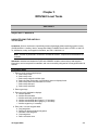
Chapter 3
MOS/Skill Level Tasks
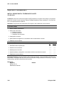
Skill Level 1
Subject Area 1: NAVIGATE
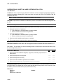
NAVIGATE USING THE AN/PSN-11
113-610-2044
Conditions: Given a requirement; operational precision lightweight global positioning system receiver
(PLGR) AN/PSN-11; battery, lithium, storage, BA-5800/U; COMSEC device KYK-13/TSEC or AN/CYZ10; initialization, setup, and waypoint information; and TM 11-5825-291-13.
Note: This task is performed in a tactical or nontactical situation. Supervision and assistance are
available.
Standards: Initialized and loaded the PLGR with COMSEC variables, entered setup and waypoint
information, receiver acquired four satellites, and user successfully navigated to five waypoints within 60
minutes.
Performance Steps
1. Enter or verify correct setup displays.
a. Select setup mode.
b. Select setup units.
c. Select setup magnetic variation type.
d. Select elevation hold mode, time reference and error display format.
e. Select setup datum and automatic OFF timer.
f. Select setup data port
g. Select setup automark.
2. Enter crypto keys.
3. Enter and verify initialization displays.
a. Initialize position.
b. Initialize time and date.
c. Initialize track and ground speed.
d. Initialize user-defined datum (page 1), if necessary.
e. Initialize user-defined datum (page 2), if necessary.
f. Initialize crypto key, if necessary.
4. Enter, edit, or review waypoint data.
a. Copy waypoints.
b. Determine distance between waypoints.
c. Calculate a new waypoint.
d. Clear waypoints.
e. Define a mission route.
12 August 2008
3-1
STP 11-25L13-SM-TG
Performance Steps
5. Check status displays to ensure acquisition of four satellites.
6. Navigate to five waypoints.
Evaluation Preparation: Setup: For this evaluation, prepare equipment and ensure equipment is
operational. Provide sufficient initialization, setup, and waypoint data information to the Soldier so that
the PLGR can be used to navigate. Prepare a navigation course.
Brief Soldier: Tell the Soldier all performance measures (PMs) must be accomplished within 60 minutes.
Performance Measures
GO
NO-GO
1. Entered or verified correct setup displays.
——
——
2. Entered crypto keys.
——
——
3. Entered and verified initialization displays.
——
——
4. Entered, edited, or reviewed waypoint data.
——
——
5. Checked status displays to ensure acquisition of four satellites.
——
——
6. Navigated to five waypoints.
——
——
Evaluation Guidance: Score the Soldier a GO if all PMs are passed. Score the Soldier a NO-GO if any
PM is failed. If the Soldier fails any PM, show what was done wrong and how to do it correctly. Have the
Soldier perform the PMs until they are done correctly.
References
Required
TM 11-5825-291-13
3-2
Related
12 August 2008
STP 11-25L13-SM-TG
Subject Area 2: CABLE AND EQUIPMENT
PERFORM CABLE MARKING PROCEDURES
113-588-2002
Conditions: Given cable, tags, manual label marker, and mechanical portable label maker, Training
Circular (TC) 24-20, engineering installation package (EIP), appropriate operation order (OPORD) and
ANSI/TIA/EIA-606-A.
Standards: Labeled the cable correctly in accordance with OPORD, EIP, TC 24-20 and ANSI/TIA/EIA606-A.
Performance Steps
1. Mark cables.
a. Marking cables is necessary to identify them during installation and to aid in troubleshooting
after the installation is complete. Identifying cables is also necessary for future planning and
system upgrades.
b. Temporarily marking cables can be done for the cable running process, and then replaced with
permanent labels once the cables are terminated.
c. Cables will be marked at both ends with two separate permanent identifications (labels). These
labels are not to be removed.
(1) The first marker (label) "TO" will be placed within 12 inches of the connector and will
indicate the bay, equipment shelf, terminal block, or position as defined in the cable
running list (CRL).
(2) The second marker (label) "FROM" will be placed within 2 inches of the first marker and
will have the connection information of the opposite end of the cable as defined in the EIP.
(3) Cables and labels will be placed so they can be easily read.
d. The Bradymarker XC Label Printer, or equivalent, is recommended for the printing adhesive
labels. Detailed instructions for the operation of these label printers are provided with each
printer.
Performance Measures
GO
1. Marked cables.
——
NO-GO
——
Evaluation Guidance: Score the Soldier a GO if all PMs are passed. Score the Soldier a NO-GO if any
PM is failed. If the Soldier fails any PM, show what was done wrong and how to do it correctly. Have the
Soldier perform the PMs until they are done correctly.
References
Required
TC 24-20
ANSI/TIA/EIA-606-A
12 August 2008
Related
3-3
STP 11-25L13-SM-TG
INSTALL CONNECTORS ON COPPER CABLE
113-588-2003
Conditions: Given tools, materials, radio frequency (RF) connectors, and copper cables.
Standards: Installed RF connectors, tested cable after connectors were installed, and knew the elements
of the RF cable.
Performance Steps
1. Identify the elements of the RF coaxial cable.
a. RF cable is a transmission line (coaxial) that consists of a center conductor and an outer
conductor separated by a dielectric.
b. The characteristic impedance of most coaxial cables is between 50 and 100 ohms; however,
special purpose coaxial cables may have impedance values outside this range.
c. The following should be considered before cable and connector components are selected:
(1) Frequency: Although primarily designed for RFs, video, and LANs, some systems use
coaxial cable for digital transmission.
(2) Power level / peak voltage: Coaxial cable can support higher frequencies (point-to-point
wiring) and has the flexibility and economy for many systems.
(3) Losses and degradation: Losses and degradation can include reflected signals, signal
attenuation, phase delay, and other impairments.
d. Identify elements of an RF cable:
(1) Center conductor:
(a) Flexible and semirigid cables use solid or stranded copper wire, copper braid wire, or
a tubular copper conductor. It can be made of copper-clad steel, silver (high temp),
and tin or nickel-plated. Other materials such as aluminum and Nichrome are also
used for special purpose cables.
( b) Rigid cables can have a center conductor similar to those used in flexible and
semirigid; however, special purpose rigid cables are have a center conductor that is
constructed from non-flexible materials, requiring special procedures for handling
and installation.
(2) The dielectric is used to physically and electrically separate the center conductor from the
outer conductor. Dielectric materials may be solid, semisolid or tape wrapped around the
center conductor. Dielectric materials used are:
(a) Air: Used primarily in certain size flexible and semiflexible cables.
(b) Polyethylene: Used mostly where temperatures will not exceed 80 degrees
centigrade.
(c) Foamed polyethylene: Semiflex helix, in sizes from 1/2 inch to 1-5/8 inches.
(d) Teflon (DuPont): Can withstand temperatures from -80 to 250 degrees.
(e) Neoprene: Also known as Polytetrafluoroethylene.
(3) The outer conductor: Acts as the return or shield.
(a) Flexible and semirigid cables usually have outer conductors of copper braid wire to
permit flexibility.
(b) Rigid cables have an outer conductor that consists of hard drawn seamless copper
tubing.
(4) The jacket or sheathing: Flexible and semirigid cables have an outer sheathing used to
protect the cable from abrasion and from harmful chemicals. Common jacket materials
are synthetic rubber, polyethylene, and synthetic resin. The jacket color may identify the
type of cable.
(5) Armor: Armor is used when greater protection for the cable is required. Armor can be
made of braided wires (aluminum or galvanized steel).
(6) Moisture Seals: The armor is sometimes rubber coated for moisture proofing.
3-4
12 August 2008
STP 11-25L13-SM-TG
Performance Steps
2. Identify the classifications of RF cable:
a. These categories are based on the temperature range, operating voltage, and the attenuation
stability.
b. RF cable is classified into three categories: Flexible, semiflexible, and rigid.
(1) Flexible RF cable is the most versatile and widely used. It consists of a center conductor,
a low-loss solid or semisolid dielectric and one or more braided outer conductors with a
waterproof covering (jacket).
(2) Semiflexible cable can be formed into moderate bends during the installation, but require
precise care and handling. It can use three forms of dielectric: air, continuous solid
(polyethylene), or semisolid foam.
(3) Rigid RF cable is a special application for permanent installation, where ruggedness, low
attenuation, and high power are the prime considerations. Rigid sections, fittings, and
accessories cannot be bent or formed in any manner. It must be installed with care and
precision, being careful not to deform or dent it.
3. Identify the types of RF Cable: The use of RF cable can suppress unwanted noise (electromagnetic
interference (EMI) and radio frequency interference (RFI)).
a. Coaxial cable is RF cable that has a center and outer conductor separated from each other by
a dielectric, with both conductors capable of carrying signal currents. It normally has a black
jacket.
(1) The outer braid is the return.
(2) In cases of potential interference, shielded cable should be used.
(3) Grounded coaxial can pass high data rates (from 20 kHz to 5 GHz), but is subject to
ground loops as well as magnetic and radiated noise.
(4) Ungrounded coaxial substantially lowers the interference.
b. Twinax cable is a two-conductor, twisted balanced wire lines having specific impedance, with a
braid shield around both wires. It normally has a blue jacket.
(1) Twinax provides protection against capacitive fields and ground loops.
(2) Twinax is limited to approximately 15 MHz, since it has high transmission losses above
this range. Twinax is used in analog and digital signal transmission.
c. Triax is an RF cable with an additional outer copper braid that acts as a shield to protect the
enclosed conductors. It normally has a yellow jacket.
(1) Triax is improved because the outer copper braid is grounded, which protects the signal
from noise, improving the "signal-to-noise" ratio.
(2) Triax cable can be used as ungrounded coaxial cable.
d. Quadrax is an RF cable that has a balanced, twisted pair, with two separate insulated braids
over the center conductors. It normally has an orange jacket.
(1) In some applications, the inner braid can be used for direct current (DC) control voltages.
Quadrax cable can also be used to provide additional EMI suppression by connecting
both shields to earth ground at one point if separate equipment ground is not available.
(2) Quadrax shields can be ungrounded to provide ground loop isolation.
4. Identify the general installation procedures for RF cable: There are many methods and procedures
used to install RF cable. For specific types, refer to the manufacturer's specifications.
a. Separation of cable: Separate cables a distance twice the diameter of the largest cable to
avoid interference. To minimize interference, separate RF cables from power and ground, plus
separate low power RF cables from high power RF cables.
b. Temperature: Avoid installing cables in high temperature areas, if this is not possible use
Teflon jacketed cable.
c. Length: The interconnecting cable is the longest transmission path. The following should be
considered when installing RF cable:
(1) Use as short a length as possible to lessen attenuation.
(2) Use as few sections as possible to keep connections to a minimum and avoid excess
attenuation.
12 August 2008
3-5
STP 11-25L13-SM-TG
Performance Steps
(3) When connecting to slide mounted equipment, allow sufficient slack to permit unrestricted
movement of the equipment.
d. Minimum bending radius: The minimum RF cable bending radius is 10 times the diameter of
the cable.
e. Vibration: To reduce vibration damage, wrap friction tape around the cable starting at the
clamp nearest the equipment and wrapping the cable 3 to 4 inches toward the equipment.
f. Abrasion: The following should be considered for prevention of abrasion to the cable jacket.
(1) Use only preformed cable straps.
(2) Do not dent or damage rigid cable; it will alter the electrical characteristics of the cable.
(3) Protect the cables with rubber grommets, sleeves, or tape where they may be subject to
abrasion.
g. To detect cable faults, check it on the reel, before installation with a Megger. The standard 500
volt Megger is the only equipment needed to test the cable for proper insulation properties.
h. Check the CRL in the EIP for cable designations. Do not use cable lengths given in the CRL,
these lengths were for planning and may not reflect the actual length needed. Measure and cut
cables, then place 2 cable tags at each end (to and from). Cable tags are NEVER removed.
5. Running and securing RF cable: All cables should be installed to allow proper access for repairs
and replacement. When cables are secured to mast or towers, start from the top and work down.
Avoid bending and do not exceed the maximum pulling (loading) tension.
a. Cables should be secured by size as follows:
(1) Outside cables, 1-5/8 inches in diameter or less should be secured every 3 feet.
(2) Outside cables, over 1-5/8 inches in diameter should be secured every 5 feet.
(3) Smaller cables should be secured at intervals of 18 inches.
(4) Inside cables are secure as signal cable, but do not use a Chicago power tie.
b. Pull cables directly from the spools by placing the spool on a cable stand. Ensure all cables
are identified and always have a spool attendant to prevent the cable from tangling and causing
undue stress on the cable.
c. Avoid pulling more than 100 feet of cable at one time. If pulling more than 100 feet cannot be
avoided, station a person at least every 100 feet to help route the cable.
d. Cables must not be subjected to unnecessary tension or excessive heat.
e. Do not bundle cables tightly.
6. Identify RF connectors: There are many types and applications of RF connectors, always install the
connectors designed for the type of cable being used.
a. Connectors are designed specifically for the outside diameter of the cable (to fit in the barrel of
the connector shell) and the inner contact diameter. This relationship of the diameters and the
dielectric between them will determine the characteristic impedance of the connector.
b. Connectors are designed so that current flows through them unchanged. Connectors are
selected to match the RF cable that has the same impedance value, maximum peak voltage
rating, and frequency limitations.
c. Connectors employ either screw-on or bayonet style couplings and can be crimp-on or
soldered.
(1) Crimping is normally used when speed of attachment is important or where it is impossible
to solder. Crimping requires a special crimp tool to install the connector to the cable.
Repair requires a new connector.
(2) Soldering requires a good soldered connection, which requires tinning the connector and
the use of flux. Do not use acid flux on electronic parts or connections. Do not overheat
the connector or damage to the dielectric may occur.
7. Assemble an RF connector: These instructions are for the Trompeter, 70 Series, "Wrench Crimp,"
concentric, Twinax, connector using 250 Diameter Twinax cable, but can generally be applied to
other types of connector assemblies.
a. Prepare the work area, gather all the tools needed, and heat the soldering iron to operating
temperature.
3-6
12 August 2008
STP 11-25L13-SM-TG
Performance Steps
b. Lay out the parts of the connector in the order of assembly and perform an inventory according
to the manufacture's part list. Ensure all parts are accounted for.
c. Place the clamping nut over the cable, with the threaded portion toward the end of the cable.
d. Butt and strip the outer jacket from the cable according to manufacturer's specifications (about
1-1/2 to 2 inches). Nicking or cutting the braid or the inner conductor may cause electrical noise
in the cable. A cable-stripping template for each type of connector will speed cable preparation.
Sometimes templates are supplied by the manufacturer.
e. Use a wire brush or the hook end of spudger to comb the braid from the butt out, until it is
smooth. Comb small portions at a time and take the time to make it even all around. Fold the
braid back over the cable butt and untangle all crossover strands of braid.
f. Cut the fillers (separators) even with the cable butt.
g. Place the cone over the center conductors and into the cable butt, between the wire braid and
the center of the cable. Considerable force may be required to seat the cone flush with the
cable butt. The clamping nut will not fit into the connector body if the cone is not seated all the
way into the cable butt.
h. Comb the wire braid back over the cone base and trim it, using flush cutters (Nippy Cutters),
even with the bottom edge of the cone.
i. Place the insulating washer over the center conductors and on top of the cone.
j. Strip the white or silver (secondary) conductor flush with the cone insulator (or as close as
possible). Strip small portions at a time and do not nick the conductor.
k. Twist the strands together and pull the secondary conductor to the side. Temporarily place the
slotted insulator on the Blue or Copper (Primary or Center) conductor, with the slotted side
(down) toward the cable butt. Mark the primary conductor even with the top of the slotted
insulator.
l. Remove the slotted insulator and strip the primary (Blue or Copper) conductor to the mark.
Place the slotted insulator on the primary (center) conductor again to check the stripped length,
if necessary remove the insulator and strip the conductor to the correct length. The insulation
will stretch, so don't strip off too much and do not knick the conductor.
m. Place the slotted insulator on the primary (center) conductor. The conductor's insulation should
touch the bottom of the slotted insulator. Twist the strands of the center conductor and tin it
lightly with 60/40 rosin core solder. Use flux, but don't use too much solder.
n. Place the center pin next to the stripped primary conductor to measure the length of the
conductor. Cut the conductor the even with the inside shoulder of the pin. The conductor
should touch the inside bottom of the pin and the pin must touch the slotted insulator.
o. Place the pin on the center (primary) conductor. The conductor must be visible in the pin's
inspection hole and it must touch the slotted insulator. Sweat-solder the pin to the conductor
through the inspection hole. Use plenty of flux to avoid a cold solder joint. Do not get solder on
the outside of the pin and do not overheat.
p. Place the pin dielectric over the center pin.
q. Place the inner shield (outer conductor) over the assembly. Align one of the slots in the shield
with the secondary conductor. Wrap the secondary conductor CLOCKWISE around the base
(inside the grove) of the inner shield. Cut the conductor at approximately 270 degrees around
the shield. The secondary conductor must not be above the rim of the grove in the shield.
r. Sweat-solder the secondary conductor to the shield in two places. Solder the end of the
conductor and a point opposite. Do not allow solder to enter the slots of the inner shield, or it
will short the primary and secondary conductors.
s. Place the body of the connector over the assembly, slide the clamp nut up to the body, and
thread the clamp nut into the connector body.
t. Use a thin wrench (such as Trompeter wrench) on the body and a suitable wrench (adjustable
or open end) on the clamp nut to tighten the connector. Turn the clamp nut to tighten, hold the
body and cable stationary while turning the nut. Do not over tighten.
u. Visually inspect the connector. Conduct a continuity test to see if any of the conductors or the
shield is shorted. When the opposite end of the cable is finished, test the cable with an
appropriate RF or bit error rate tester (BERT).
12 August 2008
3-7
STP 11-25L13-SM-TG
Performance Steps
8. Test fabricated RF cable: Cable defects may not be visible, but can be detected with proper testing.
The two primary pieces of test equipment used to test RF cable assemblies are the Megger and
BERT.
a. The Megger can to test for continuity, dielectric strength (breakdown), and shorts with or
without connectors.
b. The Data Transmission Test Set (DTTS) Model 604M, is one of the BERTs. It consists of a
transmitter and receiver that operate independent of one another. The DTTS constructs error
free data patterns and compares them on a bit-by-bit basis to detect errors induced by the
cable or connectors. Refer to the manufacture's instructions for the test set you are using.
9. Inspect RF cable and assemblies: The following quality control checks should be followed
throughout the installation.
a. Inspect and test the cable for damage or defects before installation.
b. When required, secure the cable in the same manner as signal cable.
c. Observe the minimum-bending radius at all times.
d. Butting and stripping should be done IAW the connector manufacturer's specifications. Use a
template to speed the process.
e. Place permanent cable tags on cables as prescribed.
Performance Measures
GO
NO-GO
1. Identified the elements of RF coaxial cable.
——
——
2. Identified the classifications of RF cable.
——
——
3. Identified the types of RF cable.
——
——
4. Identified the general installation procedures for RF cable.
——
——
5. Ran and secured RF cable.
——
——
6. Identified RF connectors.
——
——
7. Assembled an RF connector.
——
——
8. Tested and fabricated RF cables.
——
——
9. Inspected RF cables and assemblies.
——
——
Evaluation Guidance: Score the Soldier a GO if all PMs are passed. Score the Soldier a NO-GO if any
PM is failed. If the Soldier fails any PM, show what was done wrong and how to do it correctly. Have the
Soldier perform the PMs until they are done correctly.
References
Required
Manufacturer’s Manuals
MIL-STD-188-124B (3)
3-8
Related
12 August 2008
STP 11-25L13-SM-TG
PERFORM A SPLICE ON A PLASTIC SHEATH, PLASTIC INSULATED CABLE
113-588-2004
Conditions: Given a pre-installed cable system, a VS-3 hand tool, picabonds, muslin, B-polyethylene
tape, paper taper, and Manufacture's Manual.
Standards: Spliced the cable and restored communications.
Performance Steps
1. Make cable splice.
a. Identify one cable pair to splice from first cable using color code.
b. Identify the corresponding cable pair to splice from second cable using color code.
c. Insert the tip conductor of the first cable completely into wire support, leaving slack in the
conductor.
d. Repeat the above procedure for the tip conductor from the second cable.
e. Insert a connector into the VS-3 hand tool.
f. Hold tool steady and close the handle unit until the ratchet releases and handles open.
g. Remove the crimped connector from the tool.
h. Gauge the crimped connection.
i. Perform visual inspection of connections.
j. Correct improper connections.
k. Repeat performance steps 1a through 1h to splice remaining conductors and/or pairs.
l. Wrap conductor with muslin.
m. Wrap splice with two half-lapped layers of polyethylene tape.
n. Secure splice with paper tape.
2. Perform a bridge splice.
Note: The first bank of a bridge splice is always started from the "Y" side of the splice. The
starting point is measured 1/3 inch of the splice opening and measured from the sheath butt.
Splice the cable in banks leaving a 1/4-inch space between each bank.
a.
b.
c.
d.
e.
Prepare splice opening.
Repeat performance steps 1a through 1b (see above).
Insert the tip conductor from the main cable into the wire support below the guide pin.
Insert the tip conductor from the bridge cable into the wire support above the guide pin.
Repeat performance steps 1e through 1n (see above).
3. Perform a butt splice.
Note: Never put more than one conductor at one time when clear capping. This could cause
shorts in a working cable system.
a. Identify method of splicing.
(1) Straight method.
(2) Loop method.
b. Select two pair in the top cable and two pair in the bottom cable.
c. Separate each pair.
d. Position the hand tool on the splice opening and insert conductors individually into VS-3 hand
tool.
e. Place each conductor of each pair into the hand tool and crimp the connector on them
individually.
f. Clear cap 4 pair in each cable using the stagger-cut method.
g. Perform visual inspection of connections.
12 August 2008
3-9
STP 11-25L13-SM-TG
Performance Steps
h. Wrap conductors with muslin.
i. Wrap the splice with polyethylene tape.
j. Secure with paper tape.
Performance Measures
GO
NO-GO
1. Made cable splice.
——
——
2. Performed a bridge splice.
——
——
3. Performed a butt splice.
——
——
Evaluation Guidance: Score the Soldier a GO if all PMs are passed. Score the Soldier a NO-GO if any
PM is failed. If the Soldier fails any PM, show what was done wrong and how to do it correctly. Have the
Soldier perform the PMs until they are done correctly.
References
Required
Manufacture’s Manual
3-10
Related
12 August 2008
STP 11-25L13-SM-TG
INSTALL AC/DC POWER SOURCE FOR COMMUNICATIONS EQUIPMENT
113-588-2005
Conditions: Given tools, material, and alternating current (AC)/DC wiring, and the EIP.
Standards: Installed AC/DC wiring in compliance with the National Electric Code and the EIP.
Performance Steps
1. Install AC wire through conduit.
a. Prior to pulling conductors through conduit, consult the drawing for the correct connection, size
and number of conductors needed.
b. Short runs may be pulled from the spool or box. Temporarily mark the conductor ends for
identification.
c. The ends of long runs should be temporarily marked at the box or spool, then after being run
through the conduit, marked at the spool again before cutting.
d. Pull all conductors through the conduit before terminating and toward the distribution box when
possible.
(1) Feed the fish tape through the appropriate conduit run.
(2) Strip 12 inches of insulation off each conductor.
(3) Use one conductor as a pole and wrap the other conductors around the pole.
(4) Create an eyelet on the pole conductor by looping the wire back and wrapping about six
wraps on itself.
(5) Fasten the eyelet on the hook end of the fish tape.
(6) Feed the fish tape through the appropriate conduit run.
2. Identify wiring boxes and electrical devices.
a. The total number of splices per box depends on the size of the box and number and size of
conductors.
(1) The handy and octagon boxes can have three splices per box with a maximum of four
conductors per splice.
(2) The 4 x 4 and junction boxes can have four splices per box with a maximum of four
conductors per splice.
b. Identify the types of splices:
(1) The "in-the-middle" splice is commonly used to connect receptacles or lights in series.
(a) Measure and cut conductors "A" and "C” 6 inches from the edge of the box.
(b) Cut, strip and attach a 6-inch piece of wire (conductor B) to the device. Strip 2 inches
of insulation from the other end of the conductor.
(c) Place conductors side by side lining up the edges of insulation using needle nose
pliers. Lock a pair of hemostats behind the needle nose pliers.
(d) Evenly trim the conductors to 2 inches. Then using a pair of lineman pliers twist the
bare ends of the conductors in a CLOCKWISE direction so the conductors wrap
evenly.
(e) After twisting, trim the conductors for the proper sized wire nut. At least 1/16 inch of
insulation must be inside the wire nut.
(2) The "stand-alone" splice is used when the conductor does not terminate to a device in the
box.
(a) Measure and cut the conductors 6 inches from the edge of the box and strip off 2
inches of insulation.
(b) Cut an 8-inch piece of wire and strip 2 inches of insulation from one end.
(c) Using needle nose pliers place the conductors side by side lining up the edges of the
insulation.
(d) Evenly trim the bare conductors to 2 inches.
12 August 2008
3-11
STP 11-25L13-SM-TG
Performance Steps
(e) Using lineman pliers, twist the bare conductors CLOCKWISE. The conductors should
wrap evenly and be free of nicks.
(f) After twisting the conductors, trim to fit the correct sized wire nut.
(g) Install the wire nut with at least 1/16 inch of insulation inside.
(3) The "jumper splice" is used for distributing a single conductor that requires more than one
splice.
(a) If a conductor is to terminate to a device in the box, refer to the wiring procedure for
an "in-the-middle" splice. If no conductors terminate to a device in the box, refer to
the wiring procedure for "stand-alone" splice.
(b) Measure and cut the conductors 6 inches from the edge of the box and strip off 2
inches of insulation.
(c) Cut a piece of wire long enough to allow the wire nut of each splice to be dressed on
opposite sides of the box. Strip 2 inches of insulation from each end.
(d) Using needle nose pliers place the conductors side by side lining up the edges of the
insulation.
(e) Evenly trim the bare conductors to 2 inches and twist together with lineman pliers.
(f) Trim the splice to fit the proper sized wire nut.
(g) Treat the second splice the same as the first using the jumper conductor to link the
two together.
(h) Dress splices and close the box.
c. Identify the two methods of mounting electrical boxes:
(1) Surface mounted boxes are mounted to the surface of the wall.
(2) Flush mounted boxes are mounted flush with the surface of the wall.
(3) All boxes WILL be grounded.
d. Terminate a conductor to a device:
(1) Measure and cut the conductor 6 inches from the edge of the box.
(2) Strip 2 inches of insulation from the end of the conductor.
(3) Make a 270-degree hook (form a question mark) on the wire to be terminated.
(4) Complete the termination by placing the conductor under the screw in a CLOCKWISE
direction and tighten.
e. Perform quality control checks on device terminations:
(1) Shiners (bare wire) cannot extend more than 1/16 of an inch past the termination and is
measured from the base of the terminal or the head of the screw.
(2) Conductor insulation cannot be under the head of the screw.
(3) The conductor must wrap CLOCKWISE around the screw (in the direction the screw
tightens) between 270 and 360 degrees.
(4) The bare conductor must stay hidden under the head of the screw.
(5) Pigtails are the end of the conductor and cannot stick out from under the head of the
screw.
f. Wire a single-pole-single-throw toggle switch.
(1) Only hot conductors are wired to switches.
(2) One side of the switch is connected to the source (A) and the other side is connected to
the device (B).
(3) The neutral conductor is never connected to switches. It is routed from the distribution
panel neutral buss directly to the device, through the conduit.
(4) The ground conductor is usually not connected to switches except in special cases.
g. Wire a double-throw switch:
(1) The source (A, hot, L-1) is connected to the switch (B) with a black colored conductor.
(2) The device (D) is connected to the L-1 side of the switch (C) with a hot (L-1), black
colored conductor.
(3) The source (E, hot, L-2) is connected to the L-2 (hot) side of the switch (F) with a black
colored, conductor temporarily marked L-2.
(4) The L-2 (hot) side of the device (H) is connected to the L-2 (hot) side of the switch (G)
with a black colored conductor temporarily marked L-2.
3-12
12 August 2008
STP 11-25L13-SM-TG
Performance Steps
(5) The neutral conductor is connected to the designated neutral buss bar position at the
distribution panel and routed directly to the device through the conduit. The neutral is
never connected to a switch.
(6) The ground conductor is connected to the designated position on the ground buss bar at
the distribution panel and routed through the conduit, following the rules for grounding for
of all devices on that branch circuit.
h. Wire a three-way switch:
(1) The first terminal is wired to source (A) (hot circuit breaker).
(2) Both traveler terminals (B and D) of the first switch are connected to the next switch
traveler terminals (C and E) with a hot conductor (red).
(3) The common terminal (F) of the second switch is connected to the hot terminal of the
device to be controlled.
(4) The neutral conductor is connected to the designated position on the neutral buss bar at
the distribution panel and routed through the conduit to all devices requiring neutral
connection for that branch circuit.
(5) The ground conductor is terminated to the designated position on the ground buss bar at
the distribution panel and routed through the conduit following the grounding rules.
i. Wire a four-way switch network:
(1) Connect the common terminal (A) of a three-way switch to the designated circuit breaker
(source).
(2) Connect one of the traveler terminals (B) of this switch to one of the traveler terminals (C)
of a four-way switch using a hot conductor (black).
(3) Connect the other side of the three-way switch traveler terminal (D) to the other traveler
terminal of the four-way switch (E) using a hot conductor (red).
(4) Connect one of the opposite traveler terminals (F) of the four-way switch to one of the
traveler terminals of a second three-way switch (G) with a hot conductor (black).
(5) Connect the last traveler terminal of the four-way switch (H) to the other traveler terminal
of the second three-way switch (I) with a hot conductor (red).
(6) Connect the common terminal of the second three-way switch (J) to the device.
(7) The neutral conductor is connected to the designated position on the neutral buss bar of
the distribution panel and routed through the conduit to all devices requiring neutral in that
branch circuit.
(8) The ground conductor is terminated to the designated position on the ground buss bar of
the distribution panel and routed through the conduit following all grounding rules.
j. Wire a 120 volts AC (V AC) duplex receptacle with one or both receptacles switched.
(1) Connect the common (brass) terminal of a single-throw switch (for a switched circuit) with
a (black) insulated conductor from the source (circuit breaker or splice from a previous
circuit).
(2) Tab #1 (B) on the receptacle for the two brass terminals must be "broken" (removed)
when switching only one receptacle and a second hot wire must be ran from the source to
the receptacle. Tab #1 (B) must be "unbroken" (intact) when switching both receptacles.
(a) Connect the other common (brass) terminal on the switch to the common (brass)
terminal (A) on the duplex receptacle.
(b) If only one receptacle is to be switched, ensure the tab (B) is broken, then connect
the second hot wire from the source to the second (brass) terminal (C) on the
receptacle to provide unswitched power.
(c) If both receptacles are to be switched, ensure the tab (B) is unbroken (intact) to
provide the second receptacle switched power. A second hot wire is not needed in
this case.
(3) The silver terminal screw (D) on the receptacle must be connected to the neutral
conductor (white or gray), which originates at a neutral buss bar or a splice from a
previous circuit and goes directly to the receptacle.
(4) The silver tab (E) must stay intact ("unbroken") regardless of being switched or
unswitched to provide neutral for the second silver terminal (F) on the second receptacle.
12 August 2008
3-13
STP 11-25L13-SM-TG
Performance Steps
(5) The green ground terminal (G) on the receptacle is required to be connected with the
green insulated conductor. This conductor originates at the ground buss or a splice from
a previous outlet.
(6) Each conductor that requires a splice will use the "in-the-middle" splice and the ground will
use the "stand-alone" splice. Refer to "grounding rules".
k. Wire a 120/240 V AC duplex receptacle. Both receptacles unswitched.
(1) The source (L-1) that originates from the circuit breaker or a previous outlet splice is
connected to the brass terminal screw (C) on the receptacle.
(2) The Tab (B) must be "unbroken" to provide the 120 V AC to the first receptacle terminal
(A).
(3) The source (L-2) is connected to the opposite brass terminal (F) to provide the second leg
for the 240 V AC receptacle. This conductor must be identified as "L-2."
(4) The silver terminal screw (D) is connected to the neutral (white or gray) insulated
conductor originating at the neutral buss bar or a splice from a previous outlet. Only the
120 V AC receptacles require the neutral conductor.
(5) No Tab should exist at the neutral terminal (E). If there is a Tab between terminal screws
“D” and “F”, it must be removed or it will cause a direct short.
(6) The green terminal screw (G) is connected to the green insulated conductor, which
originates at the ground buss bar or a splice from a previous outlet.
(7) All thru-box wiring will require "in-the-middle" splice. For the ground conductors refer to
"grounding rules."
l. Wire a 120/240 V AC duplex receptacle switched.
(1) The brass terminal screw (A) is used to terminate the "switched" (L-1, black) insulated
conductor. This conductor originates at the "switched" side of a single-throw switch or a
switching network.
(2) Tab (B) must be "broken" when switching the 120 V AC receptacles.
(3) The other brass terminal screw (C) is used to terminate the "unswitched" (L-1, black)
insulated conductor. This conductor originates at the splice point of the source conductor
that feeds the single-throw switch or a switching network. This will be an "in-the-middle"
splice used to connect these conductors.
(4) The silver terminal screw (D) is used to terminate the neutral (white or gray) insulated
conductor. This conductor originates at the neutral buss bar or a splice from a previous
outlet.
(5) There must be NO Tab (E) at this location. A tab would cause a direct short between
terminals "D" and "F" on the receptacle.
(6) The brass terminal screw (F) is used to terminate the "unswitched" (L-2, black) insulated
conductor. This conductor originates at a circuit breaker, a double-throw switch, or a
splice of a previous outlet. This conductor must be identified as L-2.
(7) Green terminal screw (G) is used to terminate the ground (green) insulated conductor.
This conductor originates at the ground buss bar or a splice from a previous outlet.
(8) The "in-the-middle" splice will be used in thru-box wiring for each conductor. When
splicing the ground conductor, refer to the "grounding rules."
m. Wiring a 120 V AC basic incandescent light fixture switched or unswitched.
(1) The brass terminal screw (A) is used to terminate the (black) insulated conductor. This
conductor originates at a circuit breaker, a single-throw switch, a switching network, or a
splice.
(2) The silver terminal screw (B) is used to terminate the neutral (white or gray) insulated
conductor. This conductor originates at the neutral buss bar or a splice.
(3) The thru-box wiring will use the "in-the-middle" splice. When splicing the ground
conductor, refer to the "grounding rules".
n. Dress and terminate conductors in a distribution panel:
(1) Conductors inside the distribution panel must be routed the most direct path, taking into
consideration the following:
(a) Never cross feeder paths with branch circuit conductors.
3-14
12 August 2008
STP 11-25L13-SM-TG
Performance Steps
(b) Always dress the conductors to the back of the panel, staying tight to the back along
the corners to the breakout point. Bend the conductors 90 degrees, staying tight
against the back of the panel.
(c) Dress the conductors along the back, working toward the termination point and in a
way that prevents them from touching the buss bars.
(d) When the conductor reaches the termination point, bend it 90-degrees to lift the
conductor from the back of the panel toward the termination point.
(e) At the point where the conductor is level with the terminal, bend it 90-degree toward
the terminal, so that it will feed straight into the terminal.
(2) Terminate conductors: Always wire the distribution panel last.
(a) Always connect conductors in the order of their color. Connect green first, white (or
gray) second and black (hot) last.
(b) Connect all grounds first (green insulated conductors).
(c) Connect all neutrals (white or gray insulated conductors) second.
(d) Connect all hot (black insulated conductors) last.
(e) Trim excess but leave enough to place in the terminal.
(f) Place the conductor in or next to the terminal and mark the point to strip the
conductor of insulation.
(g) Using strippers, strip the insulation from the mark to the end of the wire.
(h) Place the conductor in the terminal and tighten the set screw.
3. Label a distribution panel.
a. Label the panels as designated by the site drawings (floor plan item number).
b. If no guidance was provided, a standard that can be used is room number and alphabetical
designator (example: "4A" would be room "4" panel "A," the next panel in the same room would
be "4B" and so on).
c. Place labels on the top center portion of the inner and outer panels using 3/4 inch characters.
d. Label group designations: (Example: 120/240 V AC 60 Hz 3 Phase).
(1) Designate the highest voltage provided by this panel.
(2) AC (alternating current) abbreviation identifies the type of current.
(3) The designator 60 Hz identifies the frequency provided by this panel.
(4) The designation 3 Phase identifies the phase relationship of the panel.
(5) Label the inner and outer panels, centered on the distribution panel number, using
3/8-inch characters.
e. Label number circuit breakers (designations). If not provided by the manufacturer, label the
circuit breakers using 3/16-inch characters.
f. The equipment/circuit designation for equipment bays or common house/commercial wiring will
be labeled on the inner panel adjacent to the circuit breakers, using 3/16-inch characters, when
designation card holders are not furnished.
(1) Label the inner panel for equipment bay designations:
(a) Label with the room number if the distribution panel is not located in the same room
as the bay or equipment.
(b) Label with the bay number of the bay or cabinet.
(c) Label with the equipment/power strips using an abbreviated term; make annotations
on the site drawings, if needed.
(d) Label with the common receptacle outlets provided at the front and inside of each
bay. Use an abbreviated term.
(2) Label AC circuit designations for common house/commercial wiring.
(a) Label using the room number the circuit supplies.
(b) Label using the type of device or equipment, such as lights, receptacles, or bay
number.
(3) Use the designation card holders, when available, labeling the equipment/circuit
designations on the individual cards provided.
12 August 2008
3-15
STP 11-25L13-SM-TG
Performance Steps
4. Identify AC safety.
a. General safety.
(1) It takes very little current to kill; as little as 100 milliamperes for two seconds can be
deadly.
(2) The path the current takes through your body will determine the extent of the injuries.
b. AC safety practices:
(1) Avoid putting your heart in the path of current flow (put one hand in your pocket).
(2) Always, wear approved rubber soled boots and use insulated tools.
(3) Never work on energized circuits.
(4) Turn off the power, remove fuses, turn off circuit breakers and check the work site with a
meter.
(5) Post danger sign on the distribution panel and put your personal safety lock on the panel.
(6) Use a light grip on tools, don't slip and hit a hot terminal.
(7) Avoid working in damp or wet locations.
(8) Always do neat work, well-dressed wires are less likely to short and cause a hazard.
(9) Always use a ground fault interrupter when working outside and whenever possible inside.
A ground fault interrupter has an internal circuitry, which monitors the current, and if it
detects a difference of five milliamperes, it will cut off the circuit within two milliseconds.
(10) Milliamperes (.001 amp)
EFFECT
1
Can just feel it.
5
Can't let go.
20 - 50
Possibly fatal.
60 & up
Probably fatal.
5. Identify DC power.
a. The big advantage of DC power systems is that when the commercial power is lost the
batteries will continue to provide power to the equipment for a limited time.
b. A DC power system can be made up of rectifier-charger, battery bank, converter, inverter, and
a power distribution system, plus redundant equipment for higher reliability.
c. Commercial AC power is converted to DC power using rectifiers to charge the battery bank and
supply DC power. DC power can be converted back to AC power using inverters for equipment
that requires AC to operate.
d. DC power sources and related equipment can be a serious source of RF noise.
(1) DC power systems are electrical noisy, because of the inductive circuitry and from
switching sizable currents.
(2) DC power systems must be adequately filtered and any internally generated noise must
be isolated from the communications equipment and the signal reference subsystem of
the facility.
6. Identify DC power wiring color code.
a. Single voltage arrangement: BLACK = HOT, WHITE = RETURN, YELLOW = REFERENCE.
b. Dual voltage arrangement: RED = PLUS, BLACK = HOT, WHITE = COMMON RETURN,
YELLOW = REFERENCE.
7. Install battery racks.
a. Install cells and racks IAW manufacturer’s instructions and the EIP.
b. Protective coatings will not be removed from the racks and any bare metal will be re-touched
with corrosive resistant paint.
c. Absolyte battery systems do not require battery racks. Supports are part of the battery module.
The accessories include installation hardware and operating instructions.
d. The Absolyte battery system can be bolted to the floor, wall or both and can be built for
earthquake protection. A maximum horizontal stack height of 8 modules is recommended for
seismic applications and ten modules for non-seismic applications.
3-16
12 August 2008
STP 11-25L13-SM-TG
Performance Steps
8. Install batteries.
a. The recommended equipment for battery installation is:
Forklift or portable boom crane.
Torpedo level (plastic).
Plywood straight edge 1/2" x 4" x 48".
Torque wrenches.
Vinyl electrical tape.
Paper wipes.
Scouring pads.
Box wrenches (metric).
Ratchet set (metric).
Line cord.
Chalk line.
Hammer drill (floor anchoring).
b. Use a hand operated crane to lift or move cells. Lead-acid cells are extremely heavy even
when not filled with acid.
c. Inspect all cells for cracks, chips, debris, broken or warped components, and other signs of
damage.
d. All terminals, interconnecting straps, and bolts will be coated with "NO-OX-ID," grease at each
terminating point.
e. The positive cell terminal connections will be made first, then the negative, to reduce the
chance of an accident.
f. The flooded cell type battery requires preparation of electrolyte. Always pour ACID INTO
WATER slowly (PAWS), NEVER water into acid. Electrolyte is available in premixed solutions,
which is safer.
g. Cells may be connected and arranged in series, parallel or series-parallel, to provide the
correct voltage and current.
h. All equipment will be wired to a circuit breaker. Under no conditions will connections be made
until all testing for continuity and shorts have been completed.
i. Flooded cell-type batteries are required to be located in a separate area.
j. To stack Absolyte modules horizontally, you must perform a tip-over procedure. The
module/base assembly (with I-beam) should be tipped over first.
CAUTION
Do not attempt to perform tip-over of module manually as serious personal
injury and module damage may result.
k. Install four lifting shackles and two lifting straps.
l. Absolyte module assemblies are identified with a circular label located on one of the module
ends. Identification codes are as follows: S = Standard Assembly, R = Reversed Assembly,
SD = Standard Assembly with Dummy, RD = Reversed Assembly with Dummy. Consult
layout-wiring diagram for proper location in assembly of battery system. Assemblies can be
rotated 180 degrees for proper polarity location.
m. To anchor Absolyte batteries, position module/base assembly in desired location. Mark floor
through I-beam holes and remove module/base assembly. Install anchoring devices and
reposition module/base assembly over anchors. Check the assembly for level in both axes and
level using the shims provided. Torque nuts to 47 Newton-Meters (35 feet-pounds).
n. The Absolyte battery system is supplied with a terminal plate assembly for the positive and
negative terminations, to provide the proper connection to the operating equipment and module
terminals. Do not connect load cables directly to module terminals; it may compromise the
battery system performance as well as the integrity of cell post seals.
12 August 2008
3-17
STP 11-25L13-SM-TG
Performance Steps
o. Cells may be connected and arranged in series, parallel or series-parallel, to provide the
correct voltage and current.
p. All terminals, interconnecting straps, and bolts will be coated with "NO-OX-ID" grease at each
terminating point.
q. Mix acid and water to make electrolyte for the flooded cell battery:
(1) Prior to mixing electrolyte or filling cells, mix a solution of baking soda and water. Mix one
gallon of water per box of baking soda to use to neutralize electrolyte (acid) spills.
(2) When preparing electrolyte for flooded cell type batteries, always POUR ACID INTO
WATER SLOWLY (PAWS), NEVER water into acid.
CAUTION
If this procedure is not followed, an extremely violent chemical reaction will
take place and could seriously injure anyone nearby.
(3) Acid mixed with water produces hydrogen gas, which is highly explosive. This means no
sparks near the area and adequate of ventilation must be provided.
(4) Electrolyte is available in premixed solutions, which is safer.
9. Identify placement and numbering of cells.
a. When installing flooded cells, the lowest numbered cells will be placed in the lower racks.
(1) Tiered racks are filled from the lowest level first, working from the center to the outside.
(2) Stepped racks are filled by installing a cell on each step, starting with the lowest step, then
working toward the highest step.
b. Once the cells are placed in the racks, cell alignment must be done.
(1) Stretch a piece of twine between the first cell terminal and the last cell terminal of each
row. Ensure the twine is on the same side of all terminals, and then align the batteries.
(2) Without tightening the straps, space each cell the length of the strap, starting at the center
and work towards the ends of each row.
c. Absolyte batteries may be arranged vertically (50A and 90A for float applications) or
horizontally (50A, 90A and 100A). Horizontal configurations are preferred.
d. A minimum of 36 inches of aisle space must be maintained adjacent to the battery bank.
e. When the application voltage requires, a dummy cell will replace a live cell in an Absolyte
module.
f. DC wiring must use the gauge and type of wire called for in the EIP. There should NOT be
more than one splice per circuit on the hot side and NO splices on the return.
g. Battery performance is based on the output at the battery; therefore, the shortest connection to
the equipment will result in maximum performance (lowest voltage drop).
10. Install connectors.
a. The crimp connector is used on multistranded cable only.
(1) Mark the cable and remove the correct amount of insulation.
(2) The insulation should be flush against the connector, with 1/8 inch of bare conductor
visible on the other side.
(3) Crimp the connector onto the cable.
b. The set screw connector can be used on stranded or solid conductor cable. Cable preparation
is the same as the crimp connector.
11. Identify safety precautions.
a. The installation of batteries will be constantly supervised and the supervisor will not physically
participate in the installation.
b. A minimum of three people will be present while work is being performed on batteries.
c. A safety briefing will be given each day before work starts. Personnel must be aware of how to
react to an accident involving battery acid.
3-18
12 August 2008
STP 11-25L13-SM-TG
Performance Steps
d. Batteries can produce hydrogen gas, which is highly explosive. Care must be taken to prevent
build-up of static charge. Before making contact with a cell, discharge static electricity by
touching a grounded surface. Adequate ventilation must be provided (exhaust fan) to prevent
dangerous levels of hydrogen gas from building up.
e. Acid must be mixed with water, POUR ACID INTO WATER SLOWLY (PAWS) and stir, NEVER
pour water into acid.
f. Prior to mixing electrolyte or filling cells with electrolyte, mix one box of baking soda to one
gallon of water.
g. If anyone gets electrolyte in their eyes, follow these steps:
(1) Close both eyes to keep eye movement minimized. This will allow the eyes to naturally
wash while the victim is being escorted to the eye washstand. DO NOT rub eyelids.
(2) Flush eyes with water for at least 15 minutes, and seek medical attention.
h. All battery rooms must have a working eyewash and shower installed before batteries can be
installed. If not provided, a large bathtub filled with a baking soda and water solution is
acceptable.
i. Proper safety gear (face shield, gloves, aprons, etc.) must be worn while working around
batteries.
j. A 3 to 5 gallon container of baking soda solution will be available to neutralize any acid
splashed.
k. Always, follow manufacturer's instruction during a battery installation and inspect all batteries
prior to filling and installing. Observe all safety requirements and recommendations.
Performance Measures
GO
NO-GO
1. Installed AC wire through conduit.
——
——
2. Identified wiring boxes and electrical devices.
——
——
3. Labeled a distribution panel.
——
——
4. Identified AC safety.
——
——
5. Identified DC power.
——
——
6. Identified DC power wiring color code.
——
——
7. Installed battery racks.
——
——
8. Installed batteries.
——
——
9. Identified placement and numbering of cells.
——
——
10. Installed connectors.
——
——
11. Identified safety precautions.
——
——
Evaluation Guidance: Score the Soldier a GO if all PMs are passed. Score the Soldier a NO-GO if any
PM is failed. If the Soldier fails any PM, show what was done wrong and how to do it correctly. Have the
Soldier perform the PMs until they are done correctly.
References
Required
MIL-HDBK-419A
MIL-STD-188-124B (3)
TB 385-4
The National Electric Code (NEC)
12 August 2008
Related
3-19
STP 11-25L13-SM-TG
INSTALL CABLE/WIRE SYSTEMS
113-588-2006
Conditions: Given cable or wire; reel unit RL-31( ) (can be vehicle mounted); marline cord; drive hooks
(installed on poles); tool equipment TE-21 and TE-33; existing poles or trees; lance poles; A-frames;
stakes; shovel; hammer; gloves; tags; grease pencil; system diagram; team of Soldiers; TC 24-20,
TM 11-3895-202-13, TM 11-5805-201-12, TM 11-6110-201-12P, TM 11-3895-209-14, TM 11-5995-20810, TM 11-5805-701-12, TM 11-5805-702-12, TM 11-5805-703-14, TM 11-5805-706-12, TM 11-5805707-12, and TM 11-6110-243-14P.
Standards: Installed cable or wire correctly.
Performance Steps
1. Install reel unit RL-31( ) for ground or flatbed use. (Refer to TM 11-3895-202-13.)
2. Install cable or wire on surface. (Refer to TC 24-20.)
3. Install cable or wire aerial.
a. Install cable or wire on poles or trees. (Refer to TC 24-20.)
b. Install terminal A-frame(s). (Refer to TC 24-20.)
(1) Install intermediate A-frame(s). (Refer to TC 24-20.)
c. Install aerial telephone cable road crossing. (Refer to TC 24-20.)
4. Bury cable or wire when appropriate. (Refer to TC 24-20.)
Performance Measures
GO
NO-GO
1. Installed reel unit RL-31( ) for ground or flatbed use.
——
——
2. Installed cable or wire on surface.
——
——
3. Installed cable or wire aerial.
——
——
4. Buried cable or wire when appropriate.
——
——
Evaluation Guidance: Score the Soldier a GO if all PMs are passed. Score the Soldier a NO-GO if any
PM is failed. If the Soldier fails any PM, show what was done wrong and how to do it correctly. Have the
Soldier perform the PMs until they are done correctly.
References
Required
TC 24-20
TM 11-3895-202-13
TM 11-3895-209-14
TM 11-5805-201-12
TM 11-5805-702-12
TM 11-5805-703-14
TM 11-5805-706-12
TM 11-5805-707-12
TM 11-5995-208-10
TM 11-6110-201-12P
TM 11-6110-243-14P
3-20
Related
12 August 2008
STP 11-25L13-SM-TG
RECOVER CABLE/WIRE SYSTEM
113-588-2010
Conditions: Given reel unit RL-31( ) (can be vehicle mounted); tool equipment TE-21 and TE-33; wire or
cable; pre-installed cable or wire reels; empty; hammer HM-1; shovel; gloves; eye protection; cargo truck
M35A2, 2 1/2-ton or equivalent; team of Soldiers; TC 24-20, TM 11-3895-202-13, TM 11-3895-209-14,
and TM 11-5995-208-10.
Standards: Recovered the cable or wire system.
Performance Steps
1. Disconnect cable from terminal equipment. (Refer to TC 24-20.)
2. Lower aerial cable to ground.
3. Recover buried field cable. (Refer to TC 24-20.)
4. Remove tags, ties, and stakes from cable or wire system. (Refer to TC 24-20.)
5. Recover field cable using reel unit RL-31( ).
Performance Measures
GO
NO-GO
1. Disconnected cable from terminal equipment.
——
——
2. Lowered aerial cable to ground.
——
——
3. Recovered buried field cable.
——
——
4. Removed tags, ties, and stakes from cable or wire system.
——
——
5. Recovered field cable using reel unit RL-31( ).
——
——
Evaluation Guidance: Score the Soldier a GO if all PMs are passed. Score the Soldier a NO-GO if any
PM is failed. If the Soldier fails any PM, show what was done wrong and how to do it correctly. Have the
Soldier perform the PMs until they are done correctly.
References
Required
TC 24-20
TM 11-3895-202-13
TM 11-3895-209-14
TM 11-5995-208-10
12 August 2008
Related
3-21
STP 11-25L13-SM-TG
INSTALL COMMERCIAL FIBER OPTIC TERMINATORS/CONNECTORS
113-632-4001
Conditions: Given a section of fiber optic cable, connectors (straight tip (ST), subminiature version A
(SMA), biconical, hot-melt), splicer's hand tools, cleaving tools, polishing adapter, lapping film,
microscope, curing oven, safety glasses, ANSI/TIA/EIA 568B/569A cabling standard, and manufacture’s
manual.
Note: Let Soldier know that assistance is available.
WARNING
Be very careful when disposing of fiber ends. The fiber creates
slivers that can cause injury. Always wear safety glasses when
working with optical fibers.
CAUTION
Do not touch bare fibers with fingers, as oil from skin can weaken the fiber
by making it brittle.
Standards: Terminated the fiber optic connector to the fiber optic cable as indicated by manufacture’s
manuals and retained a reading level of no more than 1 decibel (dB) loss per connector.
Performance Steps
1.
Inventory and clean connector parts.
a. Inspect and inventory connector package.
b. Clean connector with a dry, lint free cloth.
2.
Prepare cable and fiber.
a. Slip the strain relief boot/tube onto the buffered fiber.
b. Strip buffer to specified length as per connector.
c. Clean fiber with lint free cloth and alcohol.
3.
Prepare epoxy.
a. Mix the two components until epoxy is a uniform blue color.
b. Load the syringe with epoxy.
c. Attach the epoxy dispensing tip.
4.
Crimp connectors.
a. Insert epoxy into the connector.
b. Apply epoxy to the outer jacket and fiber.
c. Thread the connector onto the fiber.
d. Examine the epoxy bead.
Note: The epoxy bead height should be 2 to 4 fiber diameters above the ceramic tip. If not
additional epoxy must be applied around the base to build the bead to the proper height.
e.
f.
g.
3-22
Crimp the connector onto the cables outer jacket.
Install the load adapter onto the connector.
Secure the strain relief boot.
12 August 2008
STP 11-25L13-SM-TG
Performance Steps
5.
Cure proxy.
a. Heat oven to the proper temperature.
b. Place connector into one of the oven's ports.
c. Allow 20 minutes for curing time or specified time as per connector.
d. Remove connector from oven and place in the curing stand to cool for at least 5 minutes.
6.
Cleave fiber ends.
a. Remove the load adapter (allow the connector to cool to room temperature before
cleaving).
b.
Cleave the fiber end.
c.
Check the fiber end.
Note: The fiber should not protrude from the epoxy bead more than one fiber diameter.
7.
Polish fiber.
a. Prepare polishing surface using a lint free cloth dampened with alcohol.
b. Prepare the polishing adapter using a lint free cloth moistened with alcohol.
c. Polish fiber (refer to manufacture’s manual).
8.
Test fiber connector and cable.
Performance Measures
GO
NO-GO
1.
Inventoried and clean connector parts.
——
——
2.
Prepared cable and fiber.
——
——
3.
Prepared epoxy.
——
——
4.
Crimped connectors.
——
——
5.
Cured proxy.
——
——
6.
Cleaved fiber ends.
——
——
7.
Polished fiber.
——
——
8.
Tested fiber connector and cable.
——
——
Evaluation Guidance: Score the Soldier a GO if all PMs are passed. Score the Soldier a NO-GO if any
PM is failed. If the Soldier fails any PM, show what was done wrong and how to do it correctly. Have the
Soldier perform the PMs until they are done correctly.
References
Required
Manufacturer’s Manual
TB 385-4
12 August 2008
Related
3-23
STP 11-25L13-SM-TG
SPLICE COMMERCIAL FIBER OPTIC CABLE
113-632-4002
Conditions: Given a section of fiber-optic cable, splicer's hand tools, cleaving tools, polishing adapter,
reagent alcohol, microscope, mechanical splice workstation equipment, Norland optical adhesive,
Fiberlok 2501 assembly tool, fiber optic fusion splicer, safety glasses, and manufacture’s manuals.
Standards: Inspected the fiber-optic cable as indicated by manufacture’s manuals and restored
communications.
Performance Steps
1.
Identify splicing technique.
a. Norland ultra violet curing (UVC) optical splice.
b. AMP optimate mechanical fiber-optic splice.
c. Fusion splice.
d. Fiberlok optical splice.
2.
Set up workstation and equipment according to splicing technique.
3.
Prepare fiber cable according to splicing technique.
4.
Splice fiber cable according to splicing technique.
Performance Measures
GO
NO-GO
1.
Identified splicing technique.
——
——
2.
Set up workstation and equipment according to splicing technique.
——
——
3.
Prepared fiber cable.
——
——
4.
Spliced fiber cable according to splicing technique.
——
——
Evaluation Guidance: Score the Soldier a GO if all PMs are passed. Score the Soldier a NO-GO if any
PM is failed. If the Soldier fails any PM, show what was done wrong and how to do it correctly. Have the
Soldier perform the PMs until they are done correctly.
References
Required
Manufacturer’s Manuals
3-24
Related
12 August 2008
STP 11-25L13-SM-TG
PERFORM UNIT LEVEL MAINTENANCE (ULM) ON TELEPHONE TEST SET TS-3647/G
113-574-3006
Conditions: Given telephone test set TS-3647/G, a 4-inch flat-tip screwdriver, dust brush and cleaning
rags, cable CX-11230A/G, TD-1218/G or TD-1219/G, TD-1233(P)/TTC or TD-1234(P)/TTC, ground wire,
DA Form 2404 (Equipment Inspection and Maintenance Worksheet), DA Form 2408-14 (Uncorrected
Fault Record), TM 11-5805-703-14 and DA Pam 750-8.
Standards: Performed ULM, completed DA Form 2404 and DA Form 2408-14, and the telephone test set
was operational; or evacuated the defective test set to a higher maintenance level.
Performance Steps
1.
2.
Initiate DA Form 2404. (Refer to DA Pam 750-8.)
Perform routine checks. (Refer to TM 11-5805-703-14.)
a. Clean, wash, and dust.
b. Check for frayed cables.
c. Store unused items.
d. Cover unused receptacles.
e. Check for loose nuts, bolts, and screws.
Note: A ground wire should be attached from ground lug on front panel of the cable orderwire
unit (COU) to equipment being tested and remain in place while equipment is operating.
3.
Perform ULM. (Refer to TM 11-5805-703-14.)
a. Check COU batteries for operational readiness.
b. Check handset cradle, handset grommet, push-to-talk (PTT) switch, and handset cable.
CAUTION
Caution should be taken when connecting a COU to an operational cable
system. Minor errors might be produced causing interruption in data.
4.
Check COU operation with a pulse restorer. (Refer to TM 11-5805-703-14.)
5.
Check COU operation with a remote multiplexer combiner (RMC) or remote loop group
multiplexer (RLGM). (Refer to TM 11-5805-703-14.)
6.
Complete DA Form 2404 and DA Form 2408-14. (Refer to DA Pam 750-8.)
Performance Measures
GO
NO-GO
1.
Initiated DA Form 2404.
——
——
2.
Performed routine checks.
——
——
3.
Performed ULM.
——
——
4.
Checked COU operation with a pulse restorer
——
——
5.
Checked COU operation with an RMC or RLGM.
——
——
6.
Completed DA Form 2404 and DA Form 2408-14.
——
——
12 August 2008
3-25
STP 11-25L13-SM-TG
Evaluation Guidance: Score the Soldier a GO if all PMs are passed. Score the Soldier a NO-GO if any
PM is failed. If the Soldier fails any PM, show what was done wrong and how to do it correctly. Have the
Soldier perform the PMs until they are done correctly.
References
Required
DA Form 2404
DA Form 2408-14
DA Pam 750-8
TM 11-5805-703-14
3-26
Related
12 August 2008
STP 11-25L13-SM-TG
PERFORM UNIT LEVEL MAINTENANCE (ULM) ON ELECTRICAL CABLE TEST SET
AN/GTM-12
113-574-3010
Conditions: Given telephone test set AN/GTM-12, a 4-inch flat-tip screwdriver, dust brush and cleaning
rags, DA Form 2404, Form 2408-14, TM 11-6625-3292-12 and DA Pam 750-8.
Standards: Performed ULM, completed DA Form 2404 and DA Form 2408-14, and the telephone test set
was operational; or evacuated the defective test set to a higher maintenance level.
Performance Steps
1. Initiate DA Form 2404. (Refer to DA Pam 750-8.)
2. Perform routine checks. (Refer to TM 11-6625-3292-12.)
a. Clean, wash, and dust.
b. Check for frayed cables, broken connectors, or bent pins.
c. Inspect case and cover for visible damage.
d. Inspect battery pack for damaged connectors, torn plastic, broken wires, or missing Velcro
fastener.
e. Check spare fuse pack to ensure that it contains two of each fuse rated 1/2, 1, and 2 amps.
f. Tighten loose screws.
3. Complete DA Form 2404 and DA Form 2408-14. (Refer to DA Pam 750-8.)
WARNING
Do not use ungrounded extension cords when operating the
AN/GTM-12 with AC power. The AN/GTM-12 is equipped with a threewire AC power cord that grounds the instrument front panel and case
when connected to a grounded AC outlet.
Performance Measures
GO
NO-GO
1. Initiated DA Form 2404.
——
——
2. Performed routine checks.
——
——
3. Completed DA Form 2404 and DA Form 2408-14.
——
——
Evaluation Guidance: Score the Soldier a GO if all PMs are passed. Score the Soldier a NO-GO if any
PM is failed. If the Soldier fails any PM, show what was done wrong and how to do it correctly. Have the
Soldier perform the PMs until they are done correctly.
References
Required
DA Form 2404
DA form 2408-14
DA Pam 750-8
TM 11-6625-3292-12
12 August 2008
Related
3-27
STP 11-25L13-SM-TG
PERFORM UNIT LEVEL MAINTENANCE (ULM) ON TEST SET TS-4117()/G
113-574-3011
Conditions: Given test set TS-4117( )/G (with battery), pencil, DA Form 2404, DA Form 2408-14, DA
Pam 750-8, and TM 11-6625-3227-13&P.
Standards: Performed ULM, completed DA Form 2404 and DA Form 2408-14, and the test set was
operational; or evacuated the defective test set to a higher maintenance level.
Performance Steps
(Refer to TM 11-6625-3227-13&P for performance steps 2 through 11.)
1. Initiate DA Form 2404. (Refer to DA Pam 750-8.)
2. Perform routine checks. (Check for loose nuts, bolts, and screws.)
3. Check transit case.
4. Check handset.
5. Check reference cable assembly.
6. Check fiber optic loopback connector.
7. Check switch actuator assembly.
8. Check case top O-ring.
9. Check front panel.
a. OSM display.
b. Nameplate.
c. Maintenance orderwire (MOW) connector.
d. Battery cover.
e. Audible alarm.
f. Fiber Optic Cable Assembly (FOCA) test facility (FTF) connector.
g. MOW communications facility (MCF) connector.
h. Dust covers and lanyards.
10. Check battery.
11. Check optical strength meter (OSM) display.
12. Complete DA Form 2404 and DA Form 2408-14. (Refer to DA Pam 750-8.)
Performance Measures
GO
NO-GO
1. Initiated DA Form 2404.
——
——
2. Performed routine checks. (Checked for loose nuts, bolts, and screws.)
——
——
3. Checked transit case.
——
——
4. Checked handset.
——
——
5. Checked reference cable assembly.
——
——
6. Checked fiber optic loopback connector.
——
——
7. Checked switch actuator assembly.
——
——
3-28
12 August 2008
STP 11-25L13-SM-TG
Performance Measures
GO
NO-GO
8. Checked case top O-ring.
——
——
9. Checked front panel.
——
——
10. Checked battery.
——
——
11. Checked OSM display.
——
——
12. Completed DA Form 2404 and DA Form 2408-14.
——
——
Evaluation Guidance: Score the Soldier a GO if all PMs are passed. Score the Soldier a NO-GO if any
PM is failed. If the Soldier fails any PM, show what was done wrong and how to do it correctly. Have the
Soldier perform the PMs until they are done correctly.
References
Required
DA Form 2404
DA Form 2408-14
DA Pam 750-8
TM 11-6625-3227-13&P
12 August 2008
Related
3-29
STP 11-25L13-SM-TG
TROUBLESHOOT TELEPHONE CABLE WD-1( )/TT OR WF-16/U
113-588-0005
Conditions: Given a telephone cable, installed (with fault); telephone set TA-312/PT, operational (three
each, with six BA-30s); tool equipment TE-33; electrical/friction tape; lineman's gloves; two assistants; TC
24-20 and TM 11-5805-201-12.
Standards: Located and repaired a line fault and restored communications.
Performance Steps
(Refer to TC 24-20 for all performance steps, unless otherwise indicated.)
1. Verify telephone cable trouble exists.
2. Test line for trouble and identify fault. (Refer to TM 11-5805-201-12.)
a. Open.
b. Short.
c. Ground.
d. Crossed circuit.
3. Localize fault.
4. Locate fault.
5. Repair fault.
6. Retest telephone cable.
7. Restore communications.
Evaluation Preparation: Setup: Ensure the telephone cable is installed and connected to the field
phones.
Brief Soldier: Tell the Soldier that the cable must be tested for operation.
Performance Measures
(Refer to TC 24-20 for all performance steps, unless otherwise indicated.)
GO
NO-GO
1. Verified that telephone cable trouble exists.
——
——
2. Tested line for trouble and identified fault.
——
——
3. Localized fault.
——
——
4. Located fault.
——
——
5. Repaired fault.
——
——
6. Retested telephone cable.
——
——
7. Restored communications.
——
——
Evaluation Guidance: Score the Soldier a GO if all PMs are passed. Score the Soldier a NO-GO if any
PM is failed. If the Soldier fails any PM, show what was done wrong and how to do it correctly. Have the
Soldier perform the PMs until they are done correctly.
3-30
12 August 2008
STP 11-25L13-SM-TG
References
Required
TC 24-20
TM 11-5805-201-12
12 August 2008
Related
3-31
STP 11-25L13-SM-TG
TROUBLESHOOT CX-11230A/G CABLE SYSTEM
113-588-0016
Conditions: Given pre-installed, low-speed cable driven modem MD-1023; pre-installed, high-speed
cable driver modem MD-1024; pre-installed, COU C-10716; pre-installed, field cable CX-11230A/G; a
pulse form restorer TD-1218 or TD-1219; telephone test set TS-3647/G; battery BA-30 or BA-3030, six
each; ground rod MX-148/G; ground strap; stakes; HM-1 hammer; eye protection; and TM 11-5805-70314.
Standards: Tested and restored the cable system.
Performance Steps
(Refer to TM 11-5805-703-14 for all performance steps.)
1. Ground the TS-3647/G.
2. Prepare the TS-3647/G.
a. Install batteries.
b. Check batteries.
3. Connect test set to the cable system at the TD-1218 or TD-1219 pulse form restorer.
4. Perform orderwire operation.
5. Perform test procedures.
a. Locate fault.
b. Repair fault.
6. Retest the cable system.
7. Secure test set.
8. Restore the cable system.
Performance Measures
GO
NO-GO
1. Grounded the TS-3647/G.
——
——
2. Prepared the TS-3647/G.
——
——
3. Connected test set to the cable system at the TD-1218 or TD-1219 pulse form
restorer.
——
——
4. Performed orderwire operation.
——
——
5. Performed test procedures.
——
——
6. Retested the cable system.
——
——
7. Secured test set.
——
——
8. Restored the cable system.
——
——
Evaluation Guidance: Score the Soldier a GO if all PMs are passed. Score the Soldier a NO-GO if any
PM is failed. If the Soldier fails any PM, show what was done wrong and how to do it correctly. Have the
Soldier perform the PMs until they are done correctly.
3-32
12 August 2008
STP 11-25L13-SM-TG
References
Required
TM 11-5805-703-14
12 August 2008
Related
TM 11-5805-701-12
TM 11-5805-702-12
TM 11-5995-208-10
3-33
STP 11-25L13-SM-TG
TROUBLESHOOT 26-PAIR CABLE CX-4566/G
113-588-0018
Conditions: Given a faulty cable, AN/GTM-12, tools, DA Form 2404, and TM 11-6625-3292-12.
Standards: Repaired the faults and reestablished communications.
Performance Steps
(Refer to TM 11-6625-3292-12 for all performance steps.)
1. Inspect the physical appearance of the cable.
a. Breaks in cable where pairs might be showing so that possible weather conditions could
damage and affect the performance.
2. Perform troubleshooting procedures with the AN/GTM-12 by testing the CX-4566/G 26-pair cable.
Note: Perform the following three tests in the order stated.
(1) Continuity-pairs (CONT P).
(2) Insulation Resistance (IR).
(3) Cross talk (X TALK).
3. Perform conductor continuity measurement: Pair Test.
CAUTION
To avoid damage to the test set or other equipment, ensure that the first
cable you intend to test is disconnected from any load, power source, or
wiring. Never use the AN/GTM-12 to test a cable that is connected to
anything other than an approved shorting block.
a.
b.
c.
d.
Connect adapter cable W100 to connector J100.
Connect the cable to be tested to the U-185B/G connector on adapter cable W100.
Turn on the test set.
Set CABLE LENGTH switch to the length of the cable under test. If testing multiple connected
cables, set the switch to the combined length.
e. Set the AUTO/SINGLE switch to AUTO.
f. Set the FUNCTION switch to CONT P.
Note: The AN/GTM-12 sequentially tests each wire pair for open circuits. If the test proceeds
through pair 26 and the END light illuminates for approximately 20 seconds, then the cable under
test has no open conductors. If the AN/GTM-12 detects a conductor break (open circuit), the test
will stop, the fault light will illuminate, and the broken wire pair will be identified in the display.
g. Press and release the ADVANCE switch.
h. Observe the flashing TEST light (and the advancing circuit numbers in the display window if the
test set is powered in the AC or DC mode as the test sequences through each wire pair.
Note: If a fault is detected, record the number of the defective wire pair. If the END light
illuminates for approximately 20 seconds, skip to step j.
i. Repeat steps g and h until the END light illuminates.
j. Disconnect the Shorting Block P.
3-34
12 August 2008
STP 11-25L13-SM-TG
Performance Steps
4. Perform IR test.
a. Connect adapter cable W100 to connector J100.
b. Connect the cable to be tested to the U-185B/G connector on adapter cable W100.
c. Turn on the test set.
d. Set the AUTO/SINGLE switch to AUTO.
e. Set the FUNCTION switch to IR (10M).
f. Press and release the ADVANCE switch.
g. Observe the flashing TEST light and, if the test set is powered in the AC or external DC mode,
the advancing circuit numbers in the display window as the test scans forward: A01, A02, A03,
etc.
Note: If the scan halts, note the displayed conductor number. If the scan advances through B26
and the END light illuminates for approximately 20 seconds, skip the remaining steps.
h. Press and release the ADVANCE switch.
Note: Record the defective conductors shown in the display.
i. Repeat steps f through h until the test sequence advances through B26 and the END light
illuminates.
j. Set the FUNCTION switch to IR (0.1M), and repeat steps f through h.
Note: Conductors that test faulty at the 10M threshold but pass the 0.1M threshold should be
examined to determine the cause of low resistance; e.g. moisture and/or dirt on the cable hocks,
and appropriate corrective action taken.
5. Perform X TALK test.
CAUTION
To avoid damage to the test set or other equipment, ensure that the cable
that you intend to test is disconnected from any load, power source, or
wiring. Never use the AN/GTM-12 to test a cable that is connected to
anything other than an approved shorting block.
Note: The setup for X TALK is the same as for IR except the FUNCTION switch position.
a.
b.
c.
d.
e.
Connect adapter cable W100 to connector J100.
Connect the cable to be tested to the U-185B/G connector on adapter cable W100.
Turn on the test set.
Set the AUTO/SINGLE switch to AUTO.
Set the FUNCTION switch to X TALK.
Note: The stimuli are applied in turn to the wire pair displayed on the left starting with pair 01,
while the higher numbered pairs are displayed on the right. They are being scanned for a
response (cross talk).
f. Press and release the ADVANCE switch.
g. Observe the flashing TEST light and, if the test set is powered in the AC or external DC mode,
the advancing circuit numbers in the display window 01 01, 01 02, 01 26, 02 02, 02 03, etc. to
24 26, 25 25, 25 26, 26 26.
12 August 2008
3-35
STP 11-25L13-SM-TG
Performance Steps
Note: If the test sequence stops and the FAULT light illuminates, record the numbers of the
defective wire pairs as shown in the display window. If the test sequence proceeds through 25
26 and the END light illuminates, skip the remaining steps.
h. Repeat steps e and f until the test sequence proceeds through 25 26 and the END light
illuminates.
Performance Measures
GO
NO-GO
1. Inspected the physical appearance of the cable.
——
——
2. Performed troubleshooting procedures with the AN/GTM-12 by testing the CX4566/G 26-pair cable.
——
——
3. Performed Conductor Continuity Measurement: Pair Test.
——
——
4. Performed IR test.
——
——
5. Performed X TALK test.
——
——
Evaluation Guidance: Score the Soldier a GO if all PMs are passed. Score the Soldier a NO-GO if any
PM is failed. If the Soldier fails any PM, show what was done wrong and how to do it correctly. Have the
Soldier perform the PMs until they are done correctly.
References
Required
DA Form 2404
TM 11-6625-3292-12
3-36
Related
12 August 2008
STP 11-25L13-SM-TG
SET POLES
113-588-1002
Conditions: Given a 30-foot pole, pike poles, and pole supports; digging tools LC-17, LC-18, and LC-19;
digging bar; tamping bar LC-3; protective headgear; measuring tape or ruler; carrying hook and cant
hooks; anchor and anchor rod; expanding rod AH-1; guy strand; strand grip(s) (2 each); strand clamp or
automatic locking device; chain hoist; handline; tool equipment TE-21 and TE-33; shovel; bolt cutter;
eyebolt; telephone maintenance truck; and a team of seven Soldiers.
Standards: Prepared and set a pole in the ground and installed one anchor and one guy line.
Performance Steps
WARNING
A safety briefing is a must. Soldiers working or involved in lifting
heavy objects must wear protective headgear and take safety
precautions.
(Performance steps 1 and 2 can be performed with the use of a telephone maintenance truck.)
1. Dig holes for pole and anchor.
2. Raise pole and set in hole.
3. Face, straighten, and center pole.
4. Backfill and tamp the earth around pole.
5. Install anchor.
6. Backfill and tamp the earth firmly around anchor.
7. Attach guy to pole.
8. Attach guy to anchor rod.
9. Tighten guy.
Performance Measures
GO
NO-GO
1. Dug hole for pole and anchor.
——
——
2. Raised pole and set in hole.
——
——
3. Faced, straightened, and centered pole.
——
——
4. Backfilled and tamped the earth around pole.
——
——
5. Installed anchor.
——
——
6. Backfilled and tamped the earth firmly around anchor.
——
——
7. Attached guy to pole.
——
——
8. Attached guy to anchor rod.
——
——
9. Tightened guy.
——
——
12 August 2008
3-37
STP 11-25L13-SM-TG
Evaluation Guidance: Score the Soldier a GO if all PMs are passed. Score the Soldier a NO-GO if any
PM is failed. If the Soldier fails any PM, show what was done wrong and how to do it correctly. Have the
Soldier perform the PMs until they are done correctly.
References
Required
TM 9-2320-289-20P
3-38
Related
12 August 2008
STP 11-25L13-SM-TG
INSTALL AERIAL CABLE SPLICING EQUIPMENT
113-588-1074
Conditions: Given tool equipment TE-21, manila rope, 1/2-inch diameter; aerial handline; extension
ladder; slack puller; wire clamps; gloves; splicing platform; cable car; splicer's umbrella; wrench; pliers;
splicer's scissors; FM 11-372-1, FM 11-372-8, and TC 24-20.
Note: This task is performed during daylight hours. It should NOT be performed under adverse
weather conditions. Supervision and assistance are available.
Standards: Positioned the splicing equipment and made all safety checks.
Performance Steps
WARNING
Installer should be careful when erecting aerial splicing equipment,
to prevent coming in contact with power lines or power attachments.
1. Check pole for defect.
2. Check suspension strand for tension. (Refer to FM 11-373-1.)
3. Climb pole, if required. (Refer to TC 24-20.)
WARNING
Installer should look both up and down at all times while climbing a
pole. This will protect him from climbing into attachments on the pole
and from climbing over the top of the pole. Installer should visually
check to ensure that the snap engages the D-ring. Installer should
NOT depend on the sound of the keeper snapping to indicate that the
snap hook has engaged.
4. Set up ladder, if required.
WARNING
Installer should NOT move the foot of the ladder after the ladder is
lashed to the strand.
5. Remove aerial cable rings or lashing wire, if required.
6. Terminate cable lashing wire.
12 August 2008
3-39
STP 11-25L13-SM-TG
Performance Steps
7. Make proper slack in cable using the slack puller.
WARNING
Installer should NOT use the slack puller on a rusty, pitted strand.
Such a strand is likely to be broken by the slack puller. Installer
should substitute a chain hoist equipped with strand grips for the
puller.
8. Set up other splicing equipment, if required (Refer to FM 11-372-1.).
a. Splicing platform.
b. Splicer's tent.
c. Cable car.
d. Splicer's umbrella.
Note: An aerial handline should be used when setting up splicing equipment.
Evaluation Preparation: Setup: None.
Brief Soldier: Tell the Soldier that he is graded only on his assigned portion of the task.
Performance Measures
GO
NO-GO
1. Checked pole for defect.
——
——
2. Checked suspension strand for tension.
——
——
3. Climbed pole, if required.
——
——
4. Set up ladder, if required.
——
——
5. Removed aerial cable rings or lashing wire, if required.
——
——
6. Terminated cable lashing wire.
——
——
7. Made proper slack in cable using the slack puller.
——
——
8. Set up other splicing equipment, if required.
——
——
Evaluation Guidance: Score the Soldier a GO if all PMs are passed. Score the Soldier a NO-GO if any
PM is failed. If the Soldier fails any PM, show what was done wrong and how to do it correctly. Have the
Soldier perform the PMs until they are done correctly.
References
Required
FM 11-372-1
FM 11-372-8
TC 24-20
3-40
Related
12 August 2008
STP 11-25L13-SM-TG
INSTALL UNDERGROUND CABLE SPLICING EQUIPMENT
113-588-1075
Conditions: Given ventilator/blower, electrical, AC/DC, 115-V, 60-cycle, 1-HP; generator set, 3-kilowatt
(kW) gas engine, 60-Hz, 1-3 HP, 120/208-V, SKD TAC utility; fire extinguisher, carbon dioxide, with
rubber nozzle, charge, WHLD 50 lb; manhole cover hooks; carbon monoxide detector; flags; warning
signs; and barricades.
Note: This task is performed outside a manhole during daylight hours. Supervision and
assistance are available.
Standards: Made all safety checks, tested manhole atmosphere, and ventilated the manhole completely.
Performance Steps
1. Place warning devices.
a. Barricades.
b. Flags or flagmen.
c. Warning signs.
2. Remove manhole cover.
3. Test manhole atmosphere.
a. Oxygen deficiency.
b. Carbon monoxide.
4. Ventilate manhole, if required.
a. Artificial.
b. Natural.
Evaluation Preparation: Setup: None.
Brief Soldier: Tell the Soldier that he is graded only on his assigned portion of the task.
Performance Measures
GO
NO-GO
1. Placed warning devices.
——
——
2. Removed manhole cover.
——
——
3. Tested manhole atmosphere.
——
——
4. Ventilated manhole, if required.
——
——
Evaluation Guidance: Score the Soldier a GO if all PMs are passed. Score the Soldier a NO-GO if any
PM is failed. If the Soldier fails any PM, show what was done wrong and how to do it correctly. Have the
Soldier perform the PMs until they are done correctly.
References
Required
Manufacturer’s Manuals
12 August 2008
Related
3-41
STP 11-25L13-SM-TG
INSTALL A CONNECTOR ON A STRANDED FLEXIBLE COAXIAL CABLE
113-588-1106
Conditions: Given a section of coaxial cable, connector, hand tool set, solder, soldering iron, knife or
tubing cutter, clean damp cloth, safety glasses, and a Manufactures Manual.
Note: Let Soldier know assistance is available.
Standards: Installed the connector on the coaxial cable without deficiencies.
Performance Steps
WARNING
Remove all jewelry for this task. Notify Soldier of safety concerns
while operating a soldering iron.
1. Inventory connector parts.
2. Cut cable end.
3. Place nut, washer, and gasket on cable.
4. Remove outer jacket.
5. Place braid clamp on cable.
6. Cut braid and dielectric.
7. Cut and tin inner conductor.
8. Place contact on cable.
9. Position gasket, washer, and nut.
10. Install assembly.
Performance Measures
GO
NO-GO
1. Inventoried connector parts.
——
——
2. Cut cable end.
——
——
3. Placed nut, washer, and gasket on cable.
——
——
4. Removed outer jacket.
——
——
5. Placed braid clamp on cable.
——
——
6. Cut braid and dielectric.
——
——
7. Cut and tin inner conductor.
——
——
8. Placed contact on cable.
——
——
3-42
12 August 2008
STP 11-25L13-SM-TG
Performance Measures
GO
9. Positioned gasket, washer, and nut.
10. Installed assembly.
NO-GO
——
——
——
——
Evaluation Guidance: Score the Soldier a GO if all PMs are passed. Score the Soldier a NO-GO if any
PM is failed. If the Soldier fails any PM, show what was done wrong and how to do it correctly. Have the
Soldier perform the PMs until they are done correctly.
References
Required
Manufacturer’s Manuals
12 August 2008
Related
3-43
STP 11-25L13-SM-TG
INSTALL UNDERGROUND CABLE SYSTEM
113-588-1107
Conditions: Given manhole rail guard, barricades with warning lights, warning signs, warning flag, flag
and warning light stand, rodding and duct cleaning equipment, winch-operated chains, construction
vehicle with winch, rope, cable reel, cable trailer, reel jacks, cable lubrication, cable feeder, pulling eye,
pulling line, cable grip, duct tape, core-hitch eye, cable guide, loading coil and apparatus cases, duct
shields, water activated cement, cable sheave and shackle, atmosphere tester, manhole cover hooks,
ventilator, and water pump, and United States Air Force (USAF) Technical Order (TO) 31-10-3.
Note: This task is performed at a fixed installation during daylight hours. It should NOT be
performed under adverse weather conditions. Let Soldier know that assistance is available.
Standards: Installed the underground cable system, terminated cable if used and restored
communications or sealed cable ends if not used.
Performance Steps
WARNING
There are numerous safety precautions to take into consideration
with this task.
1. Conduct pre-installation activities.
a. Position safety equipment in proper locations.
b. Pump water from manholes.
c. Perform atmosphere test prior to entering in manholes.
d. Ventilate manholes.
e. Rod and clean ducts.
f. Test duct alignment.
g. Prepare cable reel and pulling apparatus.
h. Attach pulling line to the cable.
i. Install a cable grip on 25 pairs.
2. Install cable system.
a. Attach cable guide.
b. Lubricate cable.
c. Pull cable through manholes.
d. Repeat performance steps 1a through 2c for each manhole.
3. Terminate cable.
a. Install a tip cable on a main distribution frame (MDF) using distribution rings.
4. Conduct post-installation activities.
a. Seal a cable using a B end cap.
b. Tie and bond cable.
c. Place underground load coil cases.
d. Seal ducts.
3-44
12 August 2008
STP 11-25L13-SM-TG
Performance Measures
GO
NO-GO
1. Conducted pre-installation activities.
——
——
2. Installed cable system.
——
——
3. Terminated cable.
——
——
4. Conducted post-installation activities.
——
——
Evaluation Guidance: Score the Soldier a GO if all PMs are passed. Score the Soldier a NO-GO if any
PM is failed. If the Soldier fails any PM, show what was done wrong and how to do it correctly. Have the
Soldier perform the PMs until they are done correctly.
References
Required
USAF TO 31-10-3
12 August 2008
Related
3-45
STP 11-25L13-SM-TG
INSTALL A CAD-6 BURIED DISTRIBUTION TERMINAL
113-588-1108
Conditions: Given a CAD-6 distribution terminal, a ground rod, ground connector, mounting stake, a
shovel, engineer specifications, and manufacturer's manual.
Note: Supervision and assistance are available.
Standards: Installed the CAD-6 terminal according to engineer specifications.
Performance Steps
1. Determine CAD-6 terminal location using engineer specifications.
2. Prepare location - dig section of earth in an 8 x 8 square and 16 inches deep.
3. Remove covers of the CAD-6 terminal.
a. Separate upper and lower front covers.
b. Unlock the divider plate and swing it open.
Note: DO NOT use the divider plate to lift or carry the cable closure.
4. Install mounting stake.
5. Install grounding rod - place ground rod on the right side of the back plate assembly.
6. Secure back plate assembly.
a. Mount the back plate assembly to the stake.
b. Install #6 ground wire on the right side of back plate assembly.
7. Install grounding connector.
a. Clean an area 1 1/2 times the size of connector on grounding rod.
b. Install #6 ground wire on the right side of back plate assembly.
8. Ground CAD-6 terminal.
Performance Measures
GO
NO-GO
1. Determined CAD-6 terminal location using engineer specifications.
——
——
2. Prepared location - dug section of earth in an 8 x 8 square and 16 inches deep.
——
——
3. Removed covers of the CAD-6 terminal.
——
——
4. Installed mounting stake.
——
——
5. Installed grounding rod - placed ground rod on the right side of the back plate
assembly.
——
——
6. Secured back plate assembly.
——
——
7. Installed grounding connector.
——
——
8. Grounded CAD-6 terminal.
——
——
3-46
12 August 2008
STP 11-25L13-SM-TG
Evaluation Guidance: Score the Soldier a GO if all PMs are passed. Score the Soldier a NO-GO if any
PM is failed. If the Soldier fails any PM, show what was done wrong and how to do it correctly. Have the
Soldier perform the PMs until they are done correctly.
References
Required
Manufacturer’s Manuals
12 August 2008
Related
3-47
STP 11-25L13-SM-TG
PERFORM UNIT LEVEL MAINTENANCE (ULM) ON REEL UNIT RL-31()
113-588-3005
Conditions: Given reel unit RL-31( ); lint-free cloth and brush; flat-tip screwdriver; grease, automotive,
and artillery (GAA); oil, lubricating, preservative, special (PL special); adjustable wrench; initiated DA
Form 2404; DA Form 2408-14; DA Pam 750-8; and TM 11-3895-202-13.
Standards: Performed ULM, completed DA Form 2404 and DA Form 2408-14, and the reel unit was
operational; or evacuated the defective equipment to a higher maintenance level.
Performance Steps
1. Initiate DA Form 2404. (Refer to DA Pam 750-8.)
2. Perform routine checks.
a. Cleaning.
b. Preservation.
c. Dusting.
d. Washing.
e. Stowing unused items.
f. Checking for loose nuts and bolts.
3. Check mission essential equipment (for completeness).
4. Check lubrication.
5. Check brake unit.
6. Complete DA Form 2404 and DA Form 2408-14. (Refer to DA Pam 750-8.)
Performance Measures
GO
NO-GO
1. Initiated DA Form 2404.
——
——
2. Performed routine checks.
——
——
3. Checked mission essential equipment (for completeness).
——
——
4. Checked lubrication.
——
——
5. Checked brake unit.
——
——
6. Completed DA Form 2404 and DA Form 2408-14.
——
——
Evaluation Guidance: Score the Soldier a GO if all PMs are passed. Score the Soldier a NO-GO if any
PM is failed. If the Soldier fails any PM, show what was done wrong and how to do it correctly. Have the
Soldier perform the PMs until they are done correctly.
References
Required
DA Form 2404
DA Form 2408-14
DA Pam 750-8
TM 11-3895-202-13
3-48
Related
12 August 2008
STP 11-25L13-SM-TG
REPAIR PLASTIC-SHEATHED CABLE
113-588-4022
Conditions: Given aluminum tape, asbestos blanket for heat shield, cable clamps, carding brush,
channel pulling tool, chipping knife, E-pressure flange, friction tape, hammer, heat gun, heat-shrinkable
split sleeve, lash wire clamp, metal channel lengths, neoprene tape, P-compound and B-compound,
propane torch, retaining clip, 5-inch; rubber cement, shave hook, skinning knife, slack puller (if required),
splice case, splicing kit, heat-shrinkable sleeve; steel strap, tabbing shears, and vinyl tape.
Note: Supervision and assistance are available.
Standards: Repaired the plastic-sheathed cable and sealed the damaged section.
Performance Steps
1. Repair minor sheath damage to aerial, buried, and underground plastic-sheathed cable, if required.
a. Repair plastic cable sheath.
b. Repair filled plastic cable.
c. Repair plastic sheath on pressurized cable.
2. Perform a section replacement on a 25 pair plastic-sheath, plastic insulated cable, if required.
a. Select the location for the new cable installation.
b. Install new cable section temporarily.
c. Remove all hardware from preexisting cable.
d. Secure the new cable section.
e. Make splice opening.
f. Install shield bond clamp and install bond braid.
g. Install end plate on new section of cable.
h. Seal splice temporarily.
i. Establish talk circuit.
j. Half-tap splice in new cable.
k. Wrap finished splice.
3. Repair plastic-sheathed aerial, buried, and underground cable with major damage, if required.
a. Open cable.
b. Dry conductors.
c. Repair conductors.
d. Repair cable sheath.
e. Wrap core.
Note 1: When cable core is filled, repair operations should be accomplished, if possible, without
removing the filling compound. The compound is removed only from those cable conductors
which need repairing.
Note 2: When the cable core is filled, the cable core is replaced in the sheath without wrapping.
Note 3: If the cable is pressurized, a pressure plug must be installed before the cable sheath is
opened. This is to prevent loss of pressure.
4. Close cable.
a. Clean sheath and apply cement.
b. Apply tapes.
12 August 2008
3-49
STP 11-25L13-SM-TG
Performance Steps
Note: Cable damage that has excessive injury to the sheath may require the removal of a
portion of the plastic sheath. These cables may be closed by the use of a splice case or closure.
5. Repair cable terminals in plastic-sheathed cable.
a. Repair strand-mounted terminals.
b. Repair distribution terminals.
c. Repair cross-connect terminals.
6. Repair cable pedestals.
7. Locate and repair pressurization leaks.
Evaluation Preparation: Setup: None.
Brief Soldier: Tell the Soldier to observe safety precautions concerning open flames, propane gas, and
other pressurized gases.
Performance Measures
GO
NO-GO
1. Repaired minor sheath damage to aerial, buried, and underground plasticsheathed cable, if required.
——
——
2. Performed a section replacement on a 25 pair plastic-sheath, plastic insulated
cable.
——
——
3. Repaired plastic-sheathed aerial, buried, and underground cable with major
damage, if required.
——
——
4. Closed cable.
——
——
5. Repaired cable terminals in plastic-sheathed cable.
——
——
6. Repaired cable pedestals.
——
——
7. Located and repair pressurization leaks.
——
——
Evaluation Guidance: Score the Soldier a GO if all PMs are passed. Score the Soldier a NO-GO if any
PM is failed. If the Soldier fails any PM, show what was done wrong and how to do it correctly. Have the
Soldier perform the PMs until they are done correctly.
References
Required
Manufacturers’ Manual
3-50
Related
12 August 2008
STP 11-25L13-SM-TG
PERFORM POLE RESCUE OPERATION
113-588-8001
Conditions: Given a simulated victim (on pole), tool equipment TE-21, one drive hook or large flat-tip
screwdriver, one knife TL-29, safety equipment, first-aid kit, one rope of sufficient length, and FM 4-25.11.
Standards: Safely rescued the simulated victim from the pole and gave first aid.
Performance Steps
1. Plan rescue.
2. Climb pole.
3. Install drive hook or screwdriver above victim.
4. Wrap the rope twice around the drive hook or screwdriver and secure loose end of the rope to both
D-rings of victim's belt.
5. Perform artificial respiration on victim while on top of pole (if needed).
6. Cut the victim's strap (simulate).
7. Lower victim to the ground.
8. Descend pole.
9. Treat victim for shock. (Refer to FM 4-25.11.)
Evaluation Preparation: Setup: Have the Soldier ensure sufficient rope is available to complete this
task.
Brief Soldier: Tell the Soldier that he must wear rubber gloves throughout the rescue operation. When
handling energized wires, the Soldier should use only one hand if possible. If the voltage exceeds 15,000
volts, the Soldier must NOT attempt the rescue until the circuit is definitely broken.
Performance Measures
GO
NO-GO
1. Planned rescue.
——
——
2. Climbed pole.
——
——
3. Installed drive hook or screwdriver above victim.
——
——
4. Wrapped the rope twice around the drive hook or screwdriver and secured loose
end of the rope to both D-rings of victim's belt.
——
——
5. Performed artificial respiration on victim while on top of pole (if needed).
——
——
6. Cut the victim's strap (simulate).
——
——
7. Lowered victim to the ground.
——
——
8. Descended pole.
——
——
9. Treated victim for shock.
——
——
12 August 2008
3-51
STP 11-25L13-SM-TG
Evaluation Guidance: Score the Soldier a GO if all PMs are passed. Score the Soldier a NO-GO if any
PM is failed. If the Soldier fails any PM, show what was done wrong and how to do it correctly. Have the
Soldier perform the PMs until they are done correctly.
References
Required
FM 4-25.11
3-52
Related
12 August 2008
STP 11-25L13-SM-TG
MAKE A COAXIAL CABLE SPLICE
113-588-9008
Conditions: Given paper tape; cotton tape; vinyl tape; measuring tape; scotch tape; electrical tape;
muslin material; polyethylene tape; No. 5 Transflex tubing; tinned-copper sleeves, No. 16; paper clip or
test clip; lead sleeve (if required); rosin core solder; soldering iron; carding brush; hammer; pliers;
chipping knife; cutting tool; slitting tool; shears; cable stripper; splicer's scissors; gloves; test boards;
cotton sleeves; cable bonding clamp; bond wire or textile-insulated wire; and FM 11-372-1.
Note: Cables were installed, leaving approximately 5 feet on both ends for splicing. Supervision
and assistance are available.
Standards: Spliced and soldered video cable with no errors.
Performance Steps
(Refer to FM 11-372-1 for all performance steps.)
1. Prepare cables for splice opening.
a. Install temporary supports.
b. Install cable supports.
c. Measure for lead-sleeve splice.
2. Open cable.
a. Open lead-sheathed cable.
(1) Remove cable sheath (slitting required).
CAUTION
Make sure the chipping knife does NOT cut the core wrapping paper or
damage the conductors.
(2) Prepare sheath ends to protect conductors.
(a) Rotate cable, if required.
(b) Butt cable with two-paper wrapping and with four-paper wrapping.
(c) Install temporary bonds.
(3) Remove layer shields. (Exposes conductors.)
b. Open polyethylene-covered cable (non-isolated).
(1) Remove cable sheath.
(2) Remove metal sheath.
(3) Cut tabs.
(4) Install inner-sheath clamps.
(5) Install temporary bonding.
CAUTION
Gloves should be worn when removing metal sheath.
c. Open polyethylene-covered cable (isolated).
(1) Remove cable sheath.
(2) Remove metal sheath, except two strips.
(3) Fold back and tape metal strips.
12 August 2008
3-53
STP 11-25L13-SM-TG
Performance Steps
(4) Install inner-sheath clamps.
CAUTION
Gloves should be worn when removing metal sheath.
3. Expose conductors.
a. Separate binding groups.
b. Mark binding groups (color code).
4. Prepare conductors for splicing by drying out wet cable using heat gun method.
CAUTION
Desiccant should NOT be used on plastic- or rubber-insulated conductors.
5. Splice video cable.
a. Regular shield cable.
(1) Straight splice.
(2) Butt splice.
(3) Regular shield cable spliced to terminal stub.
b. Flexible shield cable.
(1) Flexible shield cable only.
(2) Splice to paper-insulated cable.
c. Regular shield video cable spliced to other cables.
(1) Nonflexible shield.
(2) Flexible shield.
Evaluation Preparation: Setup: None.
Brief Soldier: Tell the Soldier that he will be graded only on his assigned portion of the task.
Performance Measures
GO
NO-GO
1. Prepared cables for splice opening.
——
——
2. Opened cable.
——
——
3. Exposed conductors.
——
——
4. Prepared conductors for splicing by drying out wet cable using heat gun method.
——
——
5. Spliced video cable.
——
——
Evaluation Guidance: Score the Soldier a GO if all PMs are passed. Score the Soldier a NO-GO if any
PM is failed. If the Soldier fails any PM, show what was done wrong and how to do it correctly. Have the
Soldier perform the PMs until they are done correctly.
References
Required
FM 11-372-1
3-54
Related
12 August 2008
STP 11-25L13-SM-TG
TROUBLESHOOT FIBER OPTIC TRANSMISSION SYSTEM (FOTS) CABLE SYSTEM
113-632-5001
Conditions: Given the FOTS terminal, two each; FOCA CX-13295( )/G; test set TS-4117( )/G (with
battery); assistants; TM 11-6625-3227-13&P, TM 11-6020-200-10, TM 11-6020-200-23&P, DA Form
2404, DA Form 2407, and DA Pam 750-8.)
Standards: Identified and repaired faults and established communications.
Performance Steps
1. Test the FOTS for proper operation.
2. Verify all switch and control settings and equipment controls.
3. Troubleshoot the FOCA using the TS-4117( )/G from either end. (Refer to TM 11-6625-3227-13&P
and TM 11-6020-200-10.)
4. If outside of limits, have shelter operator check the fiber optic modem (FOM); if within limits, proceed
to the next connector until fault is found.
5. Replace the FOCA as needed.
6. Reestablish communications.
7. Maintain the FOCA CX-13295( )/G.
a. Visually inspect cable for burned, broken, loose, or missing connectors, splices, and physical
damage to cable. (Refer to TM 11-6020-200-23&P.)
b. Perform FOCA attenuation testing procedures using the TS-4336/G.
c. Determine malfunction of the FOCA.
d. Perform FOCA fault location procedures using the TS-4336/G.
e. Repair the CX-13295( )/G using cable repair kit MK-2495/G (if required).
f. Perform final operational test to verify normal operation of the FOCA.
8. Complete applicable blocks on DA Form 2404 and DA Form 2407. (Refer to DA Pam 750-8.)
Performance Measures
GO
NO-GO
1. Tested the FOTS for proper operation.
——
——
2. Verified all switch and control settings and equipment controls.
——
——
3. Troubleshot the FOCA using the TS-4117( )/G from either end.
——
——
4. If outside of limits, had shelter operator check the FOM; if within limits, proceeded
to the next connector until fault was found.
——
——
5. Replaced the FOCA as needed.
——
——
6. Reestablished communications.
——
——
7. Maintained the FOCA CX-13295( )/G.
——
——
8. Completed applicable blocks on DA Form 2404 and DA Form 2407.
——
——
12 August 2008
3-55
STP 11-25L13-SM-TG
Evaluation Guidance: Score the Soldier a GO if all PMs are passed. Score the Soldier a NOGO if any PM is failed. If the Soldier fails any PM, show what was done wrong and how to do it
correctly. Have the Soldier perform the PMs until they are done correctly.
References
Required
DA Form 2404
DA Form 2407
DA Pam 750-8
TM 11-6020-200-10
TM 11-6020-200-23&P
TM 11-6625-3227-13&P
3-56
Related
12 August 2008
STP 11-25L13-SM-TG
TROUBLESHOOT FIBER OPTIC CABLE
113-632-5002
Conditions: Given a pre-installed Fiber Optic Cable System, loss test set/power meter, optical fault
finder, optical TDR, or equivalent test sets, and connectors.
Standards: Identified and repaired faults and established communications.
Performance Steps
1. Ensure there is no equipment problem before checking fiber cable.
2. Conduct a visual inspection of cable.
a. Inspect for breaks.
b. Check for kinks.
c. Check for loose connections.
3. Replace faulty connectors as needed.
4. Test cable.
a. Conduct continuity test using loss test set/power meter or equivalent.
b. Test for faults and excess attenuation using optical fault finder or equivalent.
c. Test for reflection and fiber defects using optical TDR or equivalent.
d. Test for dB/kilometer (km) using optical TDR or equivalent.
e. Identify connector loss/splice loss using optical TDR or equivalent.
5. Isolate fault.
6. Repair fiber optic cable.
7. Test cable.
8. Restore service
Performance Measures
GO
NO-GO
1. Ensured there is no equipment problem before checking fiber cable.
——
——
2. Conducted a visual inspection of cable.
——
——
3. Replaced faulty connectors as needed.
——
——
4. Tested cable.
——
——
5. Isolated fault.
——
——
6. Repaired fiber optic cable.
——
——
7. Tested cable.
——
——
8. Restored service.
——
——
Evaluation Guidance: Score the Soldier a GO if all PMs are passed. Score the Soldier a NO-GO if any
PM is failed. If the Soldier fails any PM, show what was done wrong and how to do it correctly. Have the
Soldier perform the PMs until they are done correctly.
12 August 2008
3-57
STP 11-25L13-SM-TG
References
Required
ANSI/TIA/EIA-568B
ANSI/TIA/EIA-569A
Manufacturer’s Manuals
3-58
Related
12 August 2008
STP 11-25L13-SM-TG
Subject Area 3: MULTIPLEXERS
TROUBLESHOOT MULTIPLEXER TD-1233(P)/TTC OR MULTIPLEXER-COMBINER TD1234(P)/TTC
113-606-0105
Conditions: Given multiplexer TD-1233(P)/TTC or multiplexer-combiner TD-1234(P)/TTC; cable CX11230A/G; telephone set(s) TA-838/TT or equivalent; DNVT TA-1042 or equivalent; telephone cable WF16/U; power cord; batteries BA-30 or BA-3042 for TA-838/TT or equivalent; assorted circuit card
assembly (CCA) cards; TC 24-20, TM 11-5805-650-12, TM 1-5805-706-12, TM 11-5805-707-12, and
TM 11-5995-208-10.
Standards: Corrected the fault and reestablished communications.
Performance Steps
(Refer to TM 11-5805-706-12 for the TD-1233(P)/ TTC and to TM 11-5805-707-12 for the TD1234(P)/TTC for all performance steps.)
1. Check all CCA switches for correct configuration.
2. Determine the trouble.
3. Initiate self-test.
4. Localize fault.
5. Correct fault or replace defective equipment.
6. Reestablish communications.
Performance Measures
GO
NO-GO
1. Checked all CCA switches for correct configuration.
——
——
2. Determined the trouble.
——
——
3. Initiated self-test.
——
——
4. Localized fault.
——
——
5. Corrected fault or replaced defective equipment.
——
——
6. Reestablished communications.
——
——
Evaluation Guidance: Score the Soldier a GO if all PMs are passed. Score the Soldier a NO-GO if any
PM is failed. If the Soldier fails any PM, show what was done wrong and how to do it correctly. Have the
Soldier perform the PMs until they are done correctly.
References
Required
TC 24-20
TM 11-5805-650-12
TM 11-5805-706-12
TM 11-5805-707-12
TM 11-5995-208-10
12 August 2008
Related
3-59
STP 11-25L13-SM-TG
TROUBLESHOOT LINE TERMINATION UNIT (LTU) CV-4180( )
113-606-0106
Conditions: Given a pre-installed LTU CV-4180( ) and TM 11-5805-783-13&P.
Standards: Preformed troubleshooting procedures, identified the problems, took corrective action, and
reestablished communications.
Note: To properly troubleshoot the LTU as a stand-alone unit, it must first be taken off-line. This
is accomplished by turning off the LTU and setting the Group Modem Cable Length to position 5
so that the group modem function is internally looped back. Also, the LTU must be connected to
a trunk encryption device (TED) or have the TED bypass cable installed (TED red cable
connected from J1-J4 on the rear panel.)
Performance Steps
1. Verify that trouble exists.
2. Verify that the LTU has power.
3. Conduct pre-troubleshooting checks.
a. Check that the Master/Slave switch on the TIMTG CCA is in the slave position.
b. Check that the TIMBT CCA functional configuration switch is set to 2.
c. Check that the front panel Group Modem Cable Length rotary switch is set to position 5
(loopback).
d. Check that the power cable connectivity and the corresponding jumper positions have been set
on TB1 (located on backside of front panel).
4. Conduct troubleshooting procedures. (Refer to TM 11-5805-783-13&P).
5. Identify malfunctions.
6. Correct malfunctions.
a. Check that the power cable connectivity and the corresponding jumper positions have been set
on TB1 located on backside of front panel.
7. Reestablish communications.
Performance Measures
GO
NO-GO
1. Verified that the trouble existed.
——
——
2. Verified that the LTU had power.
——
——
3. Conducted pre-troubleshooting checks.
——
——
4. Conducted Troubleshooting procedures.
——
——
5. Identified malfunctions.
——
——
6. Corrected malfunctions.
——
——
7. Reestablished communications.
——
——
3-60
12 August 2008
STP 11-25L13-SM-TG
Evaluation Guidance: Score the Soldier a GO if all PMs are passed. Score the Soldier a NO-GO if any
PM is failed. If the Soldier fails any PM, show what was done wrong and how to do it correctly. Have the
Soldier perform the PMs until they are done correctly.
References
Required
TM 11-5805-783-13&P
12 August 2008
Related
3-61
STP 11-25L13-SM-TG
INSTALL MULTIPLEXER TD-1233(P)/TTC OR MULTIPLEXER-COMBINER TD-1234(P)/TTC
113-606-1001
Conditions: Given multiplexer TD-1233(P)/TTC and multiplexer-combiner TD-1234(P)/TTC; cable
CX-11230A/U; power cords; assorted circuit card assembly (CCA) cards, TM 11-5805-706-12, and
TM 11-5805-707-12.
Standards: Powered up all equipment and the system was green.
Performance Steps
1. Connect the ground, power cables, and the CX-11230A/U.
2. Check all CCA switches for correct configuration.
3. Turn power on for equipment.
4. Check for fault light(s) on the TD-1233(P)/TTC, TD-1234(P)/TTC, and CCAs.
5. Turn equipment power off properly.
Performance Measures
GO
NO-GO
1. Connected the ground, power cables, and the CX-11230A/U.
——
——
2. Checked all CCA switches for correct configuration.
——
——
3. Turned power on for equipment.
——
——
4. Checked for fault light(s) on the TD-1233(P)/TTC, TD-1234(P)/TTC, and CCAs.
——
——
5. Turned all equipment power off.
——
——
Evaluation Guidance: Score the Soldier a GO if all PMs are passed. Score the Soldier a NO-GO if any
PM is failed. If the Soldier fails any PM, show what was done wrong and how to do it correctly. Have the
Soldier perform the PMs until they are done correctly.
References
Required
TM 11-5805-706-12
TM 11-5805-707-12
3-62
Related
12 August 2008
STP 11-25L13-SM-TG
INSTALL LINE TERMINATION UNIT (LTU) CV-4180( )
113-606-1002
Conditions: Given an LTU CV-4180( ); LTU cabling set; cable CX-11230A/G; cable CX-4566/G;
telephone set(s) TA-954/TT or equivalent; DNVT TA-1042 or equivalent; telephone cable WF-16/U; power
cord; batteries BA-30 or BA-3042 for TA-838/TT or equivalent; assorted CCA cards; J-1077 box; OPORD
or a System Planner Document (SPD); TC 24-20, and TM 11-5805-783-13&P.
Standards: Installed LTU and established communications.
Performance Steps
1. Verify location of the LTU.
2. Install LTU.
3. Configure rear panel.
a. Install power cord.
b. Install cabling to rear panel connectors as required in OPORD or SPD.
c. Install CCAs in correct ports according to OPORD or SPD.
d. Set the TIMBT CCA function switch to appropriate setting.
4. Set initial switch settings on front panel.
a. Turn power switch to ON.
b. Set the Test Select switch to Operate.
c. Set Group Modem switches to appropriate settings.
d. Set digital voice orderwire (DVOW) switches to appreciate settings.
5. Identify faults in built-in test equipment (BITE) fault readings.
6. Correct faults (if any).
7. Install J-1077 terminal box(es).
8. Terminate cabling from rear panel to distant end as required by OPORD or SPD.
9. Terminate WF-16 from J-1077 to distant end as required by OPORD or SPD.
10. Establish communications.
Performance Measures
GO
NO-GO
1. Verified location of the LTU.
——
——
2. Installed LTU.
——
——
3. Configured rear panel.
——
——
4. Set initial switch settings on front panel.
——
——
5. Identified faults in BITE fault readings.
——
——
6. Corrected faults (if any).
——
——
7. Installed J-1077 terminal box(es).
——
——
8. Terminated cabling from rear panel to distant end as required by OPORD or SPD.
——
——
12 August 2008
3-63
STP 11-25L13-SM-TG
Performance Measures
GO
9. Terminated WF-16 from J-1077 to distant end as required by OPORD or SPD.
10. Established communications.
NO-GO
——
——
——
——
Evaluation Guidance: Score the Soldier a GO if all PMs are passed. Score the Soldier a NO-GO if any
PM is failed. If the Soldier fails any PM, show what was done wrong and how to do it correctly. Have the
Soldier perform the PMs until they are done correctly.
References
Required
SPD
TC 24-20
TM 11-5805-783-13&P
UNIT OPORD
3-64
Related
TM 11-3895-202-13
TM 11-5805-201-12
12 August 2008
STP 11-25L13-SM-TG
PERFORM UNIT LEVEL MAINTENANCE (ULM) ON MULTIPLEXER TD-1233(P)/TTC OR
MULTIPLEXER-COMBINER TD-1234(P)/TTC
113-606-3090
Conditions: Given multiplexer TD-1233(P)/TTC and multiplexer-combiner TD-1234(P)/TTC, flat-tip
screwdriver, dust brush and cleaning rags, cleaning solvent (Trichlorotrifluoroethane), DA Form 2404,
DA Form 2408-14, DA Pam 750-8, TM 11-5805-706-12, and TM 11-5805-707-12.
Standards: Performed ULM, completed DA Forms 2404 and 2408-14, and the equipment was
operational; or evacuated the defective equipment to a higher maintenance level.
Performance Steps
WARNING
Trichlorotrifluoroethane fumes can cause severe irritation or injury.
Provide ventilation whenever it is used.
1. Initiate DA Form 2404. (Refer to DA Pam 750-8.)
2. Perform routine checks on the TD-1233(P)/TTC or the TD-1234(P)/TTC.
3. Power on.
4. Perform BITE test.
5. Complete DA Forms 2404 and 2408-14. (Refer to DA Pam 750-8.)
Performance Measures
GO
NO-GO
1. Initiated DA Form 2404.
——
——
2. Performed routine checks on the TD-1233(P)/TTC or TD-1234(P)/TTC.
——
——
3. Powered on.
——
——
4. Performed BITE test.
——
——
5. Completed DA Form 2404.
——
——
Evaluation Guidance: Score the Soldier a GO if all PMs are passed. Score the Soldier a NO-GO if any
PM is failed. If the Soldier fails any PM, show what was done wrong and how to do it correctly. Have the
Soldier perform the PMs until they are done correctly.
References
Required
DA Form 2404
DA Form 2408-14
DA Pam 750-8
TM 11-5805-706-12
TM 11-5805-707-12
12 August 2008
Related
3-65
STP 11-25L13-SM-TG
PERFORM UNIT LEVEL MAINTENANCE (ULM) ON LINE TERMINATION UNIT (LTU) CV4180( )
113-606-3091
Conditions: Given an LTU CV-4180( ), dust brush, cleaning rags, cleaning solvent
(Ttrichlorotrifluoroethane), DA Form 2404, DA Form 2408-14, DA Pam 750-8, and TM 11-5805-78313&P.
Standards: Performed ULM, completed DA Form 2404 and DA Form 2408-14, and the equipment was
operational; or evacuated the defective equipment to a higher maintenance level.
Performance Steps
WARNING
Trichlorotrifluoroethane fumes can cause severe irritation or injury.
Provide ventilation whenever it is used. Do not use solvent near heat
or open flame.
1. Initiate DA Form 2404. (Refer to DA Pam 750-8.)
2. Perform routine checks on the LTU.
a. Check for damaged or frayed cables.
b. Store items not in use.
c. Cover unused receptacles.
d. Check for loose nuts, bolts, and screws.
e. Remove dust and loose dirt with clean, soft, lint-free cloth.
f. Remove grease, fungus, and ground in dirt with a solution of water and mild detergent and a
dampen cloth.
g. Remove dirt from plugs and connectors with a soft brush.
h. Remove grease from external cables with clean cloth soaked in trichlorotrifluoroethane.
3. Turn power switch on.
4. Perform BITE test.
a. Pass (equipment is operational).
b. Fail.
5. Complete DA Forms 2404 and 2408-14. (Refer to DA Pam 750-8.)
Performance Measures
GO
NO-GO
1. Initiated DA Form 2404.
——
——
2. Performed routine checks on the LTU.
——
——
3. Turned power switch on.
——
——
4. Performed BITE test.
——
——
5. Completed DA Forms 2404 and 2408-14.
——
——
3-66
12 August 2008
STP 11-25L13-SM-TG
Evaluation Guidance: Score the Soldier a GO if all PMs are passed. Score the Soldier a NO-GO if any
PM is failed. If the Soldier fails any PM, show what was done wrong and how to do it correctly. Have the
Soldier perform the PMs until they are done correctly.
References
Required
DA Form 2404
DA Form 2408-14
DA Pam 750-8
TM 11-5805-783-13&P
12 August 2008
Related
3-67
STP 11-25L13-SM-TG
Subject Area 4: TELEPHONE SETS
INSTALL SECURE DIGITAL TELEPHONE STU-III/STE
113-600-1001
Conditions: Given secure terminal equipment (STE) telephone, encryption card, tactical or commercial
phone line, C block or 4-pin connector, flat-tip or Phillips screwdriver, snips, and pliers TL-13A, DA Pam
25-16, and the Manufacture’s Manual.
Standards: Programmed and installed the STE telephone and established communications.
Performance Steps
1. Identify location requirements.
2. Install cord connections.
a. Handset connection.
b. Terminal connection.
c. Telephone line connection.
3. Install power connector.
4. Install software configuration in accordance with the manufacture’s manual.
5. Establish communications.
Performance Measures
GO
NO-GO
1. Identified location requirements.
——
——
2. Installed cord connections.
——
——
3. Installed power connector.
——
——
4. Installed software configuration in accordance with the manufacture’s manual.
——
——
5. Established communications.
——
——
Evaluation Guidance: Score the Soldier a GO if all PMs are passed. Score the Soldier a NO-GO if any
PM is failed. If the Soldier fails any PM, show what was done wrong and how to do it correctly. Have the
Soldier perform the PMs until they are done correctly.
References
Required
DA Pam 25-16
Manufacture’s Manual
3-68
Related
12 August 2008
STP 11-25L13-SM-TG
INSTALL VOICE OVER INTERNET PROTOCOL (VOIP) TELEPHONE
113-628-1001
Conditions: Given CAT-V cable, crimper, two RJ-45 connectors, Cisco VoIP phone, and internet protocol
(IP) phone case.
Standards: Installed the telephone set and established communications.
Performance Steps
1. Identify location requirements.
2. Install cord connections.
a. CAT-V telephone line connection. (Straight through cable.)
3. Program the telephone IAW the Cisco telephone manual.
4. Establish communications.
Performance Measures
GO
NO-GO
1. Identified location requirements.
——
——
2. Installed cord connections.
——
——
3. Programmed the telephone IAW the Cisco telephone manual.
——
——
4. Established communications.
——
——
Evaluation Guidance: Score the Soldier a GO if all PMs are passed. Score the Soldier a NO-GO if any
PM is failed. If the Soldier fails any PM, show what was done wrong and how to do it correctly. Have the
Soldier perform the PMs until they are done correctly.
References
Required
Manufacturer’s Manuals
12 August 2008
Related
3-69
STP 11-25L13-SM-TG
TROUBLESHOOT KY-68
113-600-0011
Conditions: Given DSVT TSEC/KY-68, telephone cable WF-16/U, multiplexer TD-1233(P)/TTC,
multiplexer-combiner TD-1234(P)/TTC, radio repeater set AN/TRC-138A, radio terminal set AN/TRC-173,
radio repeater set AN/TRC-174, radio terminal set AN/TRC-175, BA-1372 (1 each), TM 11-5810-329-10,
TM 11-5820-864-12-1, TM 11-5820-865-12-1, TM 11-5820-926-12-1, and TM 11-5820-931-12-1.
Note: The unkeyed DSVT TSEC/KY-68 is classified CONFIDENTIAL. It should be handled
properly. The DSVT TSEC/KY-68 is loaded with variables for the PMs.
Standards: Performed troubleshooting procedures, identified problems, took corrective action, and
reestablished communications.
Performance Steps
1. Verify that the trouble exists.
2. Verify that the KY-68 is getting power. (Refer to TM 11-5810-329-10.)
3. Troubleshoot the DSVT TSEC/KY-68 system. (Refer to TM 11-5810-329-10.)
4. Identify malfunction(s).
5. Take corrective actions. (Refer to TM 11-5810-329-10.)
6. Reestablish communications.
Performance Measures
GO
NO-GO
1. Verified that the trouble existed.
——
——
2. Verified that the KY-68 was getting power.
——
——
3. Troubleshot the DSVT TSEC/KY-68 system.
——
——
4. Identified malfunction(s).
——
——
5. Took corrective actions.
——
——
6. Reestablished communications.
——
——
Evaluation Guidance: Score the Soldier a GO if all PMs are passed. Score the Soldier a NO-GO if any
PM is failed. If the Soldier fails any PM, show what was done wrong and how to do it correctly. Have the
Soldier perform the PMs until they are done correctly.
References
Required
TM 11-5810-329-10
TM 11-5820-864-12-1
TM 11-5820-865-12-1
TM 11-5820-926-12-1
TM 11-5820-931-12-1
3-70
Related
AR 25-55
AR 380-40
DA Pam 25-380-2
TB 380-41
TM 11-5810-292-13&P
12 August 2008
STP 11-25L13-SM-TG
INSTALL TELEPHONE SET TA-312/PT
113-600-1012
Conditions: Given a telephone set, TA-312/PT; battery, BA-30 or BA-3030 (2 each); tool equipment
TE-33; installed telephone cable WD-1( )/TT; tags; grease pencil; TM 11-5805-201-12; and TC 24-20.
Standards: Install the telephone set and establish communications.
Performance Steps
1. Install the TA-312/PT on a desk, pole, or tree.
2. Set the selector switch for proper service.
3. Connect the telephone cable to the TA-312/PT.
4. Install the power source.
a. Connect the external batteries when required.
b. Install the batteries in telephone set.
Note: PMs 4a and 5 may be used if the telephone operator must have his/her hand free during
operation.
5. Connect the external headset when required.
Note: Deicing the screen may be used to prevent the transmitter from icing during extreme cold
weather.
6. Install/remove deicing screen when required.
7. Establish communications.
Evaluation Preparation: Setup: Ensure that the telephone cable is laid.
Brief Soldier: Tell the Soldier that he/she must complete an outgoing call.
Performance Measures
GO
NO-GO
1. Installed the TA-312/PT on a desk, pole, or tree.
——
——
2. Set the selector switch for the proper service.
——
——
3. Connected the telephone cable to the TA-312/PT.
——
——
4. Installed the power source.
——
——
5. Connected the external headset, when required.
——
——
6. Installed/removed the deicing screen when required.
——
——
7. Established communications.
——
——
Evaluation Guidance: Score the Soldier a GO if all PMs are passed. Score the Soldier a NO-GO if any
PM is failed. If the Soldier fails any PM, show what was done wrong and how to do it correctly. Have the
Soldier perform the PMs until they are done correctly.
12 August 2008
3-71
STP 11-25L13-SM-TG
References
Required
TC 24-20
TM 11-5805-201-12
3-72
Related
12 August 2008
STP 11-25L13-SM-TG
INSTALL DIGITAL NONSECURE VOICE TERMINAL (DNVT)
113-600-1016
Conditions: Given telephone cable WF-16/U or WD-1( )/ TT, DNVT TA-954/TT, DNVT TA-1042A/U, tool
equipment TE-33, screwdriver, TD-1233(P)/TTC or TD-1234(P)/TTC, TB 11-5805-780-15, TM 11-5805735-12, TM 11-5805-706-12, and TM 11-5805-707-12.
Standards: Installed the telephone set and established communications.
Performance Steps
(Refer to TM 11-5805-735-12 for TA-945/TT and TB 11-5805-780-15 for TA-1042A/U for all performance
steps, unless otherwise indicated.)
WARNING
Voltage as high as +56V DC may be present on telephone cables. To
avoid injury, only handle the telephone cables and binding posts to
which telephone cables are attached by the insulated areas.
1. Mount the DNVT.
2. Make bit rate select change.
Note: If the bit rate marked on the writing pad of the TA-954/TT or TA-1042A/U is incorrect for a
particular application, it must be changed.
3. Connect telephone cable.
4. Turn on proper channel card on the TD-1233(P)/TTC or the TD-1234(P)/TTC. (Refer to TM 115805-706-12 or TM 11-5805-707-12.)
5. Establish communications.
Evaluation Preparation: Set up: Ensure the telephone cable is laid and connected to the switching
equipment. Prepare the DNVT for common battery mode of operation.
Brief Soldier: Tell the Soldier he must complete an outgoing call.
Performance Measures
GO
NO-GO
1. Mounted the DNVT.
——
——
2. Made bit rate select change.
——
——
3. Connected telephone cable.
——
——
4. Turned on proper channel card on the TD-1233(P)/TTC or the TD-1234(P)/TTC.
——
——
5. Established communications.
——
——
Evaluation Guidance: Score the Soldier a GO if all PMs are passed. Score the Soldier a NO-GO if any
PM is failed. If the Soldier fails any PM, show what was done wrong and how to do it correctly. Have the
Soldier perform the PMs until they are done correctly.
12 August 2008
3-73
STP 11-25L13-SM-TG
References
Required
TB 11-5805-780-15
TM 11-5805-706-12
TM 11-5805-707-12
TM 11-5805-735-12
3-74
Related
12 August 2008
STP 11-25L13-SM-TG
INSTALL TELEPHONE SET TA-838/TT
113-600-1017
Conditions: Given telephone set TA-838/TT; telephone cable WF-16/U or WD-1( )/TT; battery BA-42
(Type C), four each, or battery BA-3042/U, four each; tool equipment TE-33; screwdriver; and
TM 11-5805-650-12.
Standards: Installed the telephone set and established communications.
Performance Steps
(Refer to TM 11-5805-650-12 for performance steps 1 through 5.)
1. Install batteries.
2. Perform pre-installation checks.
a. Select mode switch position.
b. Check side tone.
3. Mount telephone set on desk or vertical mount.
4. Determine if switchboard connections are 4-wire or 2-wire.
5. Connect WF-16/U to telephone.
6. Establish communications.
Evaluation Preparation: Setup: Ensure the telephone cable is laid and connected to the appropriate
switching equipment or another TA-838/TT.
Brief Soldier: Tell the Soldier which mode of operation and type of installation must be performed.
Performance Measures
GO
NO-GO
1. Installed batteries.
——
——
2. Performed pre-installation checks.
——
——
3. Mounted telephone set on desk or vertical mount.
——
——
4. Determined if switchboard connections were 4-wire or 2-wire.
——
——
5. Connected WF-16/U to telephone.
——
——
6. Established communications.
——
——
Evaluation Guidance: Score the Soldier a GO if all PMs are passed. Score the Soldier a NO-GO if any
PM is failed. If the Soldier fails any PM, show what was done wrong and how to do it correctly. Have the
Soldier perform the PMs until they are done correctly.
References
Required
TM 11-5805-650-12
12 August 2008
Related
3-75
STP 11-25L13-SM-TG
INSTALL KY-68
113-600-1022
Conditions: Given a DSVT TSEC/KY-68, telephone cable WF-16/U, loaded device KYK-13/TSEC, KYK15, CYZ-10 battery BA-5372, TD-1233(P)/TTC or TD-1234(P)/TTC, TM 11-5805-706-12, TM 11-5805707-12, TM 11-5810-292-13&P, and TM 11-5810-329-10.
Note: The DSVT TSEC/KY-68 is classified equipment. It should be handled properly.
Standards: Installed the DSVT, loaded variables, and established secure communications.
Performance Steps
1. Install battery.
Note: Replace battery BA-1372 or BA-5372 every six months.
2. Install the DSVT TSEC/KY-68 using telephone cable WF-16/U to connect to the TD-1233(P)/TTC or
the TD-1234(P)/TTC.
3. Ground the DVST TSEC/KY-68.
4. Load variables into the DSVT TSEC/KY-68.
a. KYK-13/TSEC.
b. KYK-15/15A.
c. AN/CYZ-10.
5. Operate the DSVT TSEC/KY-68 to initiate an outgoing secure call.
Performance Measures
GO
NO-GO
1. Installed battery.
——
——
2. Installed the DSVT TSEC/KY-68 using telephone cable WF-16/U to connect to
the TD-1233(P)/TTC or the TD-1234(P)/TTC.
——
——
3. Grounded the DSVT TSEC/KY-68.
——
——
4. Loaded variables into the DSVT TSEC/KY-68.
——
——
5. Operated the DSVT TSEC/KY-68 to initiate an outgoing secure call.
——
——
Evaluation Guidance: Score the Soldier a GO if all PMs are passed. Score the Soldier a NO-GO if any
PM is failed. If the Soldier fails any PM, show what was done wrong and how to do it correctly. Have the
Soldier perform the PMs until they are done correctly.
References
Required
TM 11-5810-292-13&P
TM 11-5810-329-10
TM 11-5805-706-12
TM 11-5805-707-12
3-76
Related
AR 25-55
AR 380-40
DA Pam 25-380-2
TB 380-41
12 August 2008
STP 11-25L13-SM-TG
PERFORM UNIT LEVEL MAINTENANCE (ULM) ON TELEPHONE SET TA-312/PT
113-600-3017
Conditions: Given telephone set TA-312/PT, battery BA-30 (two each), tool equipment TE-33, lint-free
cloth and brush, cleaning compound trichlorotrifluoroethane, DA Form 2404, DA Form 2408-14, DA Pam
750-8, and TM 11-5805-201-12.
Standards: Performed ULM, completed DA Form 2404 and DA Form 2408-14, or evacuated defective
telephone set to a higher maintenance level.
Performance Steps
WARNING
Trichlorotrifluoroethane fumes are toxic. Provide ventilation
whenever it is used.
1. Initiate DA Form 2404. (Refer to DA Pam 750-8.)
2. Perform routine checks. (Refer to TM 11-5805-210-12.)
a. Clean, dust, and wash.
b. Check for frayed cables.
c. Store unused items.
d. Cover unused receptacles.
e. Check for loose nuts, bolts, and screws.
3. Check telephone set TA-312/PT.
a. Batteries.
b. Binding posts.
c. Battery compartment.
4. Check case, telephone set.
5. Check handset.
6. Complete DA Forms 2404 and 2408-14. (Refer to DA Pam 750-8.)
Performance Measures
GO
NO-GO
1. Initiated DA Form 2404.
——
——
2. Performed routine checks. (Refer to TM 11-5805-201-12.)
——
——
3. Checked telephone set TA-312/PT.
——
——
4. Checked case, telephone set.
——
——
5. Checked handset.
——
——
6. Completed DA Forms 2404 and 2408-14.
——
——
Evaluation Guidance: Score the Soldier a GO if all PMs are passed. Score the Soldier a NO-GO if any
PM is failed. If the Soldier fails any PM, show what was done wrong and how to do it correctly. Have the
Soldier perform the PMs until they are done correctly.
12 August 2008
3-77
STP 11-25L13-SM-TG
References
Required
DA Form 2404
DA Form 2408-14
DA Pam 750-8
TM 11-5805-201-12
3-78
Related
12 August 2008
STP 11-25L13-SM-TG
PERFORM UNIT LEVEL MAINTENANCE (ULM) ON TELEPHONE SET TA-838/TT
113-600-3020
Conditions: Given an operational telephone set TA-838/TT, screwdriver, clean cloth, DA Form 2404, DA
Form 2408-14, DA Pam 750-8, and TM 11-5805-650-12.
Standards: Preformed ULM, completed DA Form 2404 and DA Form 2408-14, and the telephone set
was operational; or evacuated the defective telephone set to a higher maintenance level.
Performance Steps
1. Initiate DA Form 2404. (Refer to DA Pam 750-8.)
2. Perform routine checks. (Refer to TM 11-5805-650-12.)
CAUTION
Do not use solvents to clean any part of the telephone set.
a.
b.
c.
d.
e.
Clean, dust, and wash.
Check for frayed cables.
Store unused items.
Cover unused receptacles.
Check for loose nuts, bolts, and screws.
3. Check telephone set TA-838/TT.
a. Binding posts.
b. Battery compartment.
c. Carrying sling and tie-down strap.
d. Operational capabilities.
e. Urgent maintenance work order.
4. Check completeness.
5. Check handset retaining spring.
6. Complete DA Form 2404 and DA Form 2408-14. (Refer to DA Pam 750-8.)
Evaluation Preparation: Setup: Have another TA-838/TT perform the operational test.
Brief Soldier: Tell the Soldier that maintenance and an operational test must be performed on the
TA-838/TT.
Performance Measures
GO
NO-GO
1. Initiated DA Form 2404.
——
——
2. Performed routine checks.
——
——
3. Checked telephone set TA-838/TT.
——
——
4. Checked completeness.
——
——
12 August 2008
3-79
STP 11-25L13-SM-TG
Performance Measures
GO
NO-GO
5. Checked handset retaining spring.
——
——
6. Completed DA Form 2404 and DA Form 2408-14.
——
——
Evaluation Guidance: Score the Soldier a GO if all PMs are passed. Score the Soldier a NO-GO if any
PM is failed. If the Soldier fails any PM, show what was done wrong and how to do it correctly. Have the
Soldier perform the PMs until they are done correctly.
References
Required
DA Form 2404
DA Form 2408-14
DA Pam 750-8
TM 11-5805-650-12
3-80
Related
12 August 2008
STP 11-25L13-SM-TG
Subject Area 5: TELEPHONE MAINTENANCE TRUCK
PERFORM PREVENTIVE MAINTENANCE CHECKS AND SERVICES (PMCS) ON
TELEPHONE MAINTENANCE TRUCK
113-588-0007
Conditions: Given utility telephone maintenance truck, on-vehicle equipment tools, DA Form 2404, DA
Form 2408-14, DA Pam 750-8, and the appropriate maintenance allocation chart (MAC).
Standards: Performed maintenance, completed DA Form 2404 and DA Form 2408-14, and the
maintenance vehicle was operational; or evacuated to higher echelon maintenance.
Performance Steps
1. Initiate DA Form 2404. (Refer to DA Pam 750-8.)
2. Perform routine checks.
3. Perform operator maintenance. (Refer to the appropriate MAC.)
4. Complete DA Form 2404 and DA Form 2408-14. (Refer to DA Pam 750-8.)
Performance Measures
GO
NO-GO
1. Initiated DA Form 2404.
——
——
2. Performed routine checks.
——
——
3. Performed operator maintenance.
——
——
4. Completed DA Form 2404 and DA Form 2408-14.
——
——
Evaluation Guidance: Score the Soldier a GO if all PMs are passed. Score the Soldier a NO-GO if any
PM is failed. If the Soldier fails any PM, show what was done wrong and how to do it correctly. Have the
Soldier perform the PMs until they are done correctly.
References
Required
DA Form 2404
DA Form 2408-14
DA Pam 750-8
12 August 2008
Related
3-81
STP 11-25L13-SM-TG
OPERATE TELEPHONE MAINTENANCE TRUCK
113-588-2007
Conditions: Given an operator and a utility telephone maintenance truck.
Standards: Leveled the telephone maintenance truck, operated derrick, and moved boom to work
position.
Performance Steps
1. Position truck on solid, level ground as close as possible to the work area.
2. Engage parking brake and chock the wheels.
3. Engage power take-off (PTO).
4. Lower the outriggers.
5. Operate derrick and move boom to work position.
Performance Measures
GO
NO-GO
1. Positioned truck on solid, level ground as close as possible to the work area.
——
——
2. Engaged parking brake and chocked the wheels.
——
——
3. Engaged PTO.
——
——
4. Lowered the outriggers.
——
——
5. Operated derrick and moved boom to work position.
——
——
Evaluation Guidance: Score the Soldier a GO if all PMs are passed. Score the Soldier a NO-GO if any
PM is failed. If the Soldier fails any PM, show what was done wrong and how to do it correctly. Have the
Soldier perform the PMs until they are done correctly.
References
Required
Manufacturer’s Manuals
3-82
Related
12 August 2008
STP 11-25L13-SM-TG
Subject Area 6: LAN/WAN SUBSTATION
PERFORM SOLDERING TECHNIQUES
113-583-1001
Conditions: Given a soldering iron, solder, flux (rosin), material, and notes.
Standards: Identified quality of soldered electrical terminations.
Performance Steps
1. Identify a soldering termination.
a. Electrical termination: The connection of an electrical conductor to various fixed terminals
usually by one of two methods—soldering or mechanical.
b. Soldered termination: A mechanical connection between wire and terminal, which are bonded
by applying solder.
c. Mechanical: The process of joining a wire and a terminal by external pressure.
d. Soldering: The process of joining two metals (wire and terminal) by heat transfer, using a low
temperature cohesive alloy.
e. Solder: The solder used in electronics is an alloy usually made with 60 percent tin and 40
percent lead.
(1) The greater the tin content the lower temperature required to liquefy the solder.
(2) When soldering conductors use a rosin core solder. Never use acid core solder on
electrical connections.
f. Flux (rosin): This is a chemical cleaning agent that promotes wetting of metals and helps
prevent oxidation.
(1) Reliable solder connections can only be accomplished with clean surfaces. Flux removes
oxides, which must melt at a lower temperature, so it can do its job before the actual
soldering process.
(2) Available in liquid or paste form. Flux disintegrates when heated and usually dissipates
during the soldering process.
g. Oxidation: This is the chemical corrosion of metal that takes place quickly at temperatures
above 750 degrees Fahrenheit.
2. Identify types of soldering irons.
a. Soldering irons come in various sizes and capacity ratings (wattage) to suit requirements for
size, gauge, and type of terminals and conductors.
(1) Sixty to one hundred watt irons are suitable for most conductor terminations and electrical
applications.
(2) The speed of soldering required along with the solder melting temperature. The 60/40alloy solder melts around 374 degrees Fahrenheit.
b. Clean the tip of the soldering iron before using, by heating it and wiping it on a damp sponge.
c. To properly perform a temperature test, place solder on the tip, when solder melts, the iron is at
its working temperature.
3. Identify different soldering iron tips.
a. Screwdriver shaped soldering tips are used for most electrical applications.
b. Pencil point shaped tips are used for light duty.
c. Pyramid shaped tips are for heavy duty.
d. Chisel shaped tips are for special applications.
e. Tinning the soldering iron tip cleans the tip by applying flux and a light coat of solder, which
retards oxidation and aids in heat transfer.
12 August 2008
3-83
STP 11-25L13-SM-TG
Performance Steps
4. Identify soldering aids.
a. A soldering fork is used to form wires.
b. A soldering iron holder is used for safety, temperature control and convenience. When not in
use, the iron should be kept in a holder, with its tip clean and coated with a small amount of
solder.
c. The solder bag is used for protection from solder splash and serves as a receptacle for debris,
which helps keep the work area clean.
d. A damp sponge is used to remove excess solder from the iron tip and help keep it clean.
5. Make a solder connection.
a. Solder shall be applied to the connection when the temperature reaches the point where solder
will readily melt.
b. The connection shall have a smooth, bright appearance with solder covering the top of the
conductor and a concave slope flowing down between the terminal and the lower half of the
conductor.
c. Identify unacceptable soldered connections (faults):
(1) There will be no solder on the opposite side of the pin, unless it has been indicated that
both sides are to be soldered.
(2) The insulation of the wire should not be burned and should not be in the soldered
connection.
(3) Too much solder can cover faults, which may not make a good connection.
(4) Not enough solder.
(5) No spikes on the solder.
(6) Let the soldered connection cool naturally or a cold solder connection may occur.
6. Identify methods of soldering.
a. The roll-n-wipe method is used on larger surfaces such as terminal pins.
(1) Place the edge of the tip of the soldering iron on the terminal.
(2) When the terminal is hot enough to melt solder, apply the solder under the tip and roll the
tip over the terminal. Immediately remove the solder and soldering iron from the terminal
with the same rolling motion.
b. The sweat method applies heat and solder to the area until the solder melts, wicking solder
through the connection. This is the preferred method for soldering splices, tubular pins and
small terminals.
(1) Heat the connection with the tip of the soldering iron and apply the solder to the other
side. When the solder melts, remove the soldering iron.
(2) Avoid moving the connection until it has cooled.
c. The wipe-on method is used for inaccessible areas only:
(1) When using this method, apply flux to the connection first.
(2) Apply solder to the tip of the iron and wipe the solder on the connection.
7. Identify the six basic steps of quality soldering.
a. Heat the connection not the solder.
b. Apply the solder to the terminal.
c. Remove the solder allowing no excess solder to remain.
d. Remove the heat. Do not burn insulation on wires.
e. Allow the connection to cool.
f. Inspect.
8. Identify safety requirements for soldering.
a. Solder used in electronics contains 40 percent lead and requires good ventilation at the work
area. Never solder directly over the work piece.
b. Wear safety goggles when soldering or desoldering.
c. Keep the work area clear of debris.
d. Use soldering iron holder to eliminate burns.
3-84
12 August 2008
STP 11-25L13-SM-TG
Performance Steps
e. Never flick solder from the soldering iron, wipe solder from the tip.
f. Inspect the soldering iron for defects (frayed cord, cracked handle).
g. Never solder a live circuit.
Performance Measures
GO
NO-GO
1. Identified a soldering termination.
——
——
2. Identified types of soldering irons.
——
——
3. Identified different soldering iron tips.
——
——
4. Identified soldering aids.
——
——
5. Made a solder connection.
——
——
6. Identified methods of soldering.
——
——
7. Identified the six basic steps of quality soldering.
——
——
8. Identified safety requirements for soldering.
——
——
Evaluation Guidance: Score the Soldier a GO if all PMs are passed. Score the Soldier a NO-GO if any
PM is failed. If the Soldier fails any PM, show what was done wrong and how to do it correctly. Have the
Soldier perform the PMs until they are done correctly.
References
Required
Manufacturer’s Manuals
TB 385-4
12 August 2008
Related
3-85
STP 11-25L13-SM-TG
INSTALL CABLE RACK AND WIRE WAY
113-583-1002
Conditions: Given straight splicing clamp, corner clamp, corner braces, edge clamp, hanger clips "J''
bolt, rack feet, wireway (cable duct), tools, material and references.
Standards: Installed cable rack or wireway in accordance with engineering plans.
Performance Steps
1. Identify cable rack and wireway.
a. A cable rack is a ladder-like assembly used wherever exposed cable is acceptable. It consists
of two parallel side members called "stringers" and cross straps that are welded at regular
intervals. It comes in widths from 5 to 24 inches and lengths from 10 to 20 feet.
b. A cable rack shall be used in full stock lengths wherever possible.
2. Plan installation of cable rack and wireway.
a. Cable racks and wireways shall be installed in accordance with the EIP and applicable
drawings.
b. Existing equipment, building structures and future expansion must be considered during
engineering and installation.
c. Cable racks should be installed before any other equipment is installed at new sites.
d. Cable racks must have proper clearance to provide cable service to equipment and to eliminate
any difficulty running and securing cables in the future.
e. Installing cable racks close to pipes, radiators, windows, doors or anything that could damage
the cables should be avoided.
3. Identify cable rack hardware.
a. Straight splicing clamp:
(1) Straight clamps are used to join lengths of cable rack or to attach feet to the end of a rack.
(2) The spacing requirement between the ends of the stringers is 3/8-inch minimum to 5/8inch maximum and the space should be equal on both sides of the bolt.
(3) A maximum of one splice is allowed between cable rack supports.
b. Corner clamps:
(1) These clamps are used to end a run, make turns, form "T" intersections and for horizontal
offsets.
(2) The maximum gap between the rack and the end of the stringer is 1/8 inch.
c. Corner braces: These are used for bracing and when cables require a gradual turn at
intersections.
d. Edge clamps: These 90 and 45-degree edge clamps are used for vertical offsets to change
vertical direction (inside and outside bends).
(1) Cable racks that form a 90-degree vertical turn, with a turn radius of 6 inches or less, can
be joined by two sets of 90-degree edge clamps.
(2) To form a 90-degree vertical turn, with a turn radius of more than 6 inches, four sets of 45degree edge clamps can be used to join the cable rack.
e. Hanger clips: Used to secure threaded rod to the cable rack stringer.
f. The "J" bolt: Used to mount rack to framing bar or channel.
g. Rack feet: Used to attach rack ends to walls or the floor.
4. Identify the types of support.
a. Overhead cable rack support (direct and indirect mounting):
(1) Overhead support uses the permanent building structural members or securing devices
installed at the time the cable rack was installed. The site must be laid out and marked on
the floor where the equipment will be installed.
3-86
12 August 2008
STP 11-25L13-SM-TG
Performance Steps
(2) Overhead indirect support: Spacing often makes it impractical to support cable racks with
threaded rods attached directly to the ceiling.
(3) Securing a threaded rod to a wooden ceiling joist with loads of more than 300 pounds
requires drilling a hole through the joist. A load of less than 300 pounds can be secured
with a threaded rod attached to a bracket and two 3/8 inch by 2 inch long (minimum) lag
screws.
(4) Direct overhead support is established when the support rods can be anchored directly
into the ceiling.
(5) Other attachments used with threaded rods are; "I" beam clamps, "U" shaped brackets,
and drive pins. Check to make sure the maximum load is not exceeded.
WARNING
Never drill holes through an "I" beam to attach anchoring devices; it
could weaken the structure.
(6) For greater strength, a 5/8-inch threaded rod is recommended for all cable rack
installations.
(7) Special hangers for a single threaded rod may be used to support cable racks up to 15
inches in width. Racks wider than 15 inches require two threaded rods.
(8) Cable racks may be supported directly from the ceiling using threaded rods by one of two
methods. Two threaded rods are required if the width of the cable rack is 20-inches or
more. Support of 12-and 15-inch cable racks may be provided by a short length of lipped
channel fastened flush against the ceiling by one securing device in the center of the
channel and a pair of threaded rods attached.
(9) Unless unavoidable, threaded rods should not be bent to provide an offset. If no other
means is practicable, bends are permissible: however, they shall not exceed 20 degrees
and the offset distance shall not be more than 4-inches.
(10) When splicing threaded rod is necessary, the ends of the threaded rod will be butted
together inside the splice coupling, so the ends can be seen through the sight hole.
b. Floor or equipment cable rack support:
(1) Metal support channel on top of equipment cabinets, frames, relay racks or bays can be
used to support cable rack.
(2) Cable rack that goes down to the floor is supported by cable rack feet attached to the
ends of the stringers with straight clamps.
(3) When a vertical cable rack passes through a floor to another level, the cable rack must be
secured to each floor it passes through to prevent overloading the lowest support.
c. Vertical (Wall) cable rack support.
(1) Vertical building structural members, such as walls or columns, can be used to support
rack.
(2) If prefabricated brackets are unavailable, steel angles braced by threaded rod may be
used.
(3) Framing bar can support a load up to three feet past its last support.
(4) If necessary, the framing bar may be extend to the wall and supported with a wallmounted bracket.
d. Mutual cable rack:
(1) Used to support a cable rack perpendicular or parallel to another cable rack.
(2) The maximum of 18 inches between the two racks is allowed.
(3) The load capacity of the upper rack supports must be enough to bear the additional load
of the lower rack.
(4) The upper cable rack hanger clips, with hex nuts, are used to adjust the required space
between racks.
12 August 2008
3-87
STP 11-25L13-SM-TG
Performance Steps
5. Install supporting material.
a. Lipped channel (Unistrut is a brand name) can be square or rectangular, made of 12, 14, or 16
gauge steel alloy and comes in 10-foot or 20-foot lengths. It can be used with a 5/8 inch
threaded rod to support cable rack or duct.
(1) The open side of slotted channel has two 90-degree bends. These edges are the
clamping ridges designed to position and lock a special nut, commonly called a spring nut.
One side of the nut has two grooves that engage the clamping ridges and the other side
has a spring to keep it in place. When the nut is drawn tight against the clamping ridges,
the grooves in the nut securely bridge the sides of the channel together.
(2) The ends of spliced channels should be butted together; however, in no case shall the
space exceed 1/8 inch.
(3) Cable racks may be supported by a lipped channel trapeze.
b. Framing bar may be used instead of a lipped channel except where the channel must mount
directly to the ceiling. Framing bars require a minimum of 2-inches between the ceiling and the
top of the bar.
c. Channel may also be used for rack support.
(1) Channel comes in 20-foot lengths and measures 2 inches by 9/11 of an inch.
(2) All rules for Unistrut and framing bar apply to channel.
(3) The use of channel for rack support is limited to short runs and light loads.
d. A maximum of one splice between supports is permitted for cable rack, threaded rod, lipped
channel, channel, or framing bar.
6. Identify safe load capacities.
7. Reduce cable rack.
a. Cut cable rack squarely.
b. Measure and mark the length of cable rack to be cut.
c. Cut the stringers at the marks with a hand hacksaw or a power hacksaw.
d. If the cable rack must be cut at the junction of the stringers and a cross strap, remove the cross
strap by cutting as close to the stringer as possible without cutting the stringer.
e. File off all burrs on the ends of the stringer.
8. Ground bond cable rack.
a. Cable rack will be strapped (bonded) at all junctions and splices with 12 American wire gauge
(AWG) or larger, solid or stranded, wire on the outside of the stringer to ensure a continuous
electrical connection.
b. After all cable rack sections have been strapped, bond the cable rack to the equipotential plane
or inner ground ring 2 feet from each end and at intervals of 50 feet along the run.
c. The cable rack must also be bonded to the fault protection bus bar in the nearest AC
distribution panel with 6 AWG green insulated wire.
9. Install wireway (cable duct).
a. Duct is used where physical protection of cables and conductors is required.
b. Wireway or duct is available with or without knockouts, in lengths of 1 foot, 2 feet, 3 feet, 4 feet,
5 feet, and 10 feet.
c. Duct runs are hung in place using tray supports at 5-foot intervals. Where a duct run
terminates, it shall be supported within 1 foot of the end.
d. Universal hanger can be used to mount duct to the ceiling, walls or floor.
e. Duct can be supported using a trapeze style support made with Unistrut or similar material.
f. Wireway may be supported in a combination of approved methods.
10. Identify restrictions of wireway.
a. Power cables:
(1) Cannot exceed 600 volts.
3-88
12 August 2008
STP 11-25L13-SM-TG
Performance Steps
(2) The total number of conductors cannot exceed 20 percent of the cross sectional area, or
contain more than 30 conductors, at any given point.
(3) The wireway must not be filled more than 75 percent of its cross sectional area, where
taps and splices are made.
b. Communications cable:
(1) The total number of conductors cannot exceed 30 percent of the cross sectional area at
any one point and there is no restriction on the number of conductors.
(2) Communications cable splices and taps have the same restrictions as power splices and
taps.
11. Install wireway couplings.
a. Couplings must be secured on at least three sides with screws and star washers. The screw
heads should always be on the inside of wireway.
b. Always tighten screws/nuts as tightly as possible to give maximum mechanical rigidity and
electrical continuity.
c. Fittings and hardware for wireway: All unused openings must be sealed.
(1) Closing plates are used to seal the ends of ducts or fittings.
(2) Telescope fittings or slip-fittings provide a means to adjust the length of straight
connections from ½ inch to 11 ½ inches.
(3) End fittings connect duct to panels and cabinets. Cutting a hole and drilling mounting
holes to match the end fitting can result in a solid connection free of rough edges.
(4) Elbows are available in 22 ½, 45, and 90 degree bends and attach with a connector or
coupling.
(5) Tee fittings are available to branch standard sections of duct.
(6) Junction boxes have four openings that can be coupled with connectors. Unused
openings are sealed with closing plates.
(7) Pull boxes (large junction box) has six openings, two sides with one opening each and two
sides with two openings each. Pull boxes are used when several ducts are spliced
together at a junction.
(8) Reducer fittings are available to connect different sizes of duct together. The standard
reducer sizes are 4" X 4" duct to 2 - 1/2" x 2 - 1/2", 6" X 6" to 4" X 4", 8" X 8" to 6" X 6,"
and 12" X 12" to 8" X 8" duct.
(9) Transposition sections permit the wireway to be rotated 90 degrees and continue the "layin" feature.
(10) Partitions or barriers can be installed inside the duct to separate power and
communication cables.
d. Wireway and duct, whether used for signal or power conductors, must be made electrically
continuous by bonding together all sections. Wireway must have a grounding strap installed at
each junction and splice. Connect all sections and lids using straps fabricated from 12 AWG (or
larger), solid or stranded, green, insulated, copper wire.
(1) All wireway or duct will be bonded to the fault protection subsystem at power panels.
(2) One continuous green wire can be used for bonding the wireway.
(3) Bond all sections, including lids, with straps fabricated from 12 AWG (or larger), solid or
stranded, green insulated wire. Star washers will be used to provide a good bond.
(4) When all sections have been strapped, the duct is bonded to ground not more than 2 feet
from each end of the run and every 50 feet along the run, using #6 AWG green wire.
Note: Only one ground point for each lid is required.
Performance Measures
GO
NO-GO
1. Identified cable rack and wireway.
——
——
2. Planned installation of cable rack and wireway.
——
——
12 August 2008
3-89
STP 11-25L13-SM-TG
Performance Measures
GO
NO-GO
3. Identified cable rack hardware.
——
——
4. Identified the types of support.
——
——
5. Installed supporting material.
——
——
6. Identified safe load capacities.
——
——
7. Reduced cable rack.
——
——
8. Grounded bond cable rack.
——
——
9. Installed wireway (cable duct).
——
——
10. Identified restrictions of wireway.
——
——
11. Installed wireway couplings.
——
——
Evaluation Guidance: Score the Soldier a GO if all PMs are passed. Score the Soldier a NO-GO if any
PM is failed. If the Soldier fails any PM, show what was done wrong and how to do it correctly. Have the
Soldier perform the PMs until they are done correctly.
References
Required
The National Electric Code (NEC)
3-90
Related
12 August 2008
STP 11-25L13-SM-TG
INSTALL DISTRIBUTION FRAMES
113-583-1003
Conditions: Given a MDF, intermediate distribution frame (IDF) or combined distribution frame (CDF),
tools and notes.
Standards: Installed a distribution frame.
Performance Steps
1. Identify the purpose of distribution frames.
a. Distribution frames are necessary to protect and support the cable, cross-connects, and the
ground buss bar.
b. Distribution frames provide a point of permanent termination for outside and inside cables.
c. Distribution frames provide temporary connection (cross-connects) between outside and inside
cables to and from fixed equipment.
2. Identify the construction of a distribution frame.
a. Distribution frames are normally made of an open metal framework of steel with cross
members that form vertical and horizontal arms.
b. Frames require a minimum clearance of 36 inches from the sides and ends for maintenance.
c. Components of a frame:
(1) Floor angle - Attaches to the floor and supports the verticals (uprights). The length of
each angle depends on the number of verticals it mounts and may require several floor
angles to complete a frame.
(2) Top angle - Secures the top of the verticals (uprights).
(3) Verticals (uprights) - Are the basic support framework and are fastened on 8-inch centers.
(4) Diagonal brace - A brace welded to the protector-mounting bar and the vertical angle for
support.
(5) Reinforcing stud - Supports the vertical side.
(6) Transverse arm - Welded to vertical angle and used to support cable.
(7) Jumper ring bar - Three steel bars extending the length of the frame to attach jumper
rings.
(8) Jumper ring - Used to guide the cross-connects (jumper wire) from vertical to horizontal.
(9) Terminal block mounting bar - Used only on the horizontal side to support terminal blocks.
(10) Terminal blocks - Used to terminate cable.
(11) Guard rail support - Protects the terminal blocks from damage by ladders or other
equipment.
(12) End guard - Protects the ends of the frame.
(13) Finishing bar - A flat, finish bar that increases the strength of the frame and protects
personnel from sharp ends of the bars.
(14) Grounding buss bar - A flat, copper bar that is attached to the station ground.
3. Install a distribution frame.
a. The first step is to inspect the floor plan, which should show the location of equipment and
significant features of the building.
b. Install angles:
(1) Angles for distribution frames are furnished in the required lengths.
(2) Floor angles are placed on vertical face lines as shown on floor plans. When two or more
angles are required, fasten each angle loosely until an entire line has been installed.
Angles must be level with each other, to build up the low spots on the floor use light metal
shims the width of the floor angle and at least 4 inches long.
12 August 2008
3-91
STP 11-25L13-SM-TG
Performance Steps
(3) To level high spots, cut out floor covering or the floor itself. The maximum level deviation
allowable between two floor angles is an 1/8 inch and the entire length of a row cannot
exceed a 3/8 inch deviation from level.
c. Frame verticals (uprights):
(1) After installing the floor angles, install the vertical angles at each end.
(2) Secure the end verticals with nuts and bolts to the top angle.
(3) Install all the remaining intermediate verticals.
(4) Check the horizontal and vertical planes with a plumb line and a level before tightening
the assembly.
(5) Install the permanent bracing before removing the temporary bracing.
d. Continue frame installation: After the floor angels and verticals have been assembled, continue
as follows:
(1) Before mounting a ground buss bar to the frame, the paint must be removed at the point
of contact of each vertical (bonding) and a thin coating of petroleum jelly applied to the
contact surface. Secure the ground buss bar at each vertical upright.
(2) The jumper ring bars are fastened in place at the bottom, the fifth, and the top of the frame
using jumper rings on each vertical. Ensure that the offset end of each jumper ring bar is
toward the growing end of the frame. Jumper rings are installed on each shelf and each
vertical.
(3) Install the terminal block mounting bars on the front of the transverse arms. Make certain
that the offset end of each mounting bar is toward the growing end of the frame.
(4) Install the guardrail supports and the front, rear, and end guardrails.
(5) After the entire framework has been installed, tighten all nuts and bolts and retouch any
portion of the framework where the paint has been marred.
e. Install terminal blocks: Components of a terminal block are the fanning, mounting and
clamping strips.
(1) Vertical terminal block: The left side of a vertical block is the cable or permanent side.
The right side is the temporary or maintenance side. Pin count is from front to back and
rows are counted from top to bottom.
(2) Horizontal terminal block: The top of a horizontal block is the temporary or maintenance
side and the bottom of the block is the cable or permanent side. Pin count is from front to
back and rows are counted left to right.
4. Identify types of distribution frames.
a. The MDF:
(1) The purpose and function of the MDF is to enable the greater part of the wiring in a dial
central office to be permanent.
(2) The MDF is generally located directly above the cable vault or near an outside frame.
(3) The vertical side of an MDF terminates the outside cable from the cable vault. The vertical
side of the MDF has protector blocks, which provide electrical protection and termination
points for cross connects. Verticals on an MDF are counted from the permanent end to
the growing end and start with the number "1." The protector blocks are identified by cable
number and pair counts.
(4) The horizontal side of an MDF mounts terminal blocks, which provide termination points
for cables that run to and from the IDF or circuit concentration frame bay. There are no
protector blocks on the horizontal side of the MDF.
(5) The horizontally mounted terminal blocks extend from one end of the frame to the other
and each level or row is known as a shelf. When lettering the horizontal side of an MDF,
the shelves are lettered alphabetically from the bottom to the top starting with "A" and
skipping I and O. To identify a terminal block on the horizontal side, start with the shelf
letter, then the vertical upright (e.g. "B5").
b. IDF.
(1) The purpose and function of the IDF is to provide a neat and flexible point of termination
for inside cable and cross-connects.
3-92
12 August 2008
STP 11-25L13-SM-TG
Performance Steps
(2) The IDF has no protector devices and all equipment, patch panels, and tie cables from the
MDF will appear on the IDF. This is also the main work area for most wiring changes and
in-house troubleshooting.
(3) The ideal location for an IDF is parallel to the MDF and near the equipment it is serving.
(4) The vertical side of the IDF terminates the cable from the horizontal side of the MDF.
(a) The vertical side of the IDF mounts terminal blocks that are bolted to mounting clips.
The terminal block assignment drawings show the size and placement of terminal
blocks that are mounted from the bottom to the top. The mounted blocks cannot be
out of alignment more than 1/8 inch per foot, nor more than 1/4 inch over the entire
row.
(b) The vertical terminal blocks of an IDF are lettered alphabetically from bottom to top
and the verticals are numbered from the permanent end starting with "01."
Identification of a vertical block will be listed with the number first and the letter
second (e.g. 03D).
(5) The horizontal side of an IDF terminates cable from the equipment and patch panels.
(a) The horizontal terminal blocks are mounted on the terminal mounting bars. Terminal
block assignment drawings show the size and placement of the terminal blocks to be
mounted. The terminal blocks cannot be out of alignment more than 1/8 inch per
foot, nor more than 1/4 inch over the entire length.
(b) To count horizontal shelves and terminal blocks on an IDF, use the same method as
on the horizontal side of the MDF.
c. CDF:
(1) The purpose of a CDF is to combine the functions of an MDF and an IDF.
(2) The location of the MDF portion of a CDF is usually directly over the cable vault and at a
right angle to the equipment.
(3) The MDF portion of a CDF mounts protector blocks on the vertical side and terminal
blocks on the horizontal side. The IDF portion mounts terminal blocks on the vertical and
horizontal sides.
(a) The count on the vertical side of a CDF starts at the point where both frames join, the
MDF portion is counted starting with 1 to the growing end and the IDF portion is
counted starting with 01 to the growing end.
(b) When counting the horizontal side of a CDF, the shelves of both frames are lettered
from the bottom to the top. To identify a particular horizontal terminal block, the letter
is first then the number, (starting with "A1" for the MDF and "A01" for the IDF).
Performance Measures
GO
NO-GO
1. Identified the purpose of distribution frames.
——
——
2. Identified the construction of a distribution frame.
——
——
3. Installed a distribution frame.
——
——
4. Identified types of distribution frames.
——
——
Evaluation Guidance: Score the Soldier a GO if all PMs are passed. Score the Soldier a NO-GO if any
PM is failed. If the Soldier fails any PM, show what was done wrong and how to do it correctly. Have the
Soldier perform the PMs until they are done correctly.
References
Required
Manufacturer’s Manuals
12 August 2008
Related
3-93
STP 11-25L13-SM-TG
INSTALL ANCHORING DEVICES
113-583-1004
Conditions: Given a drill, drill bit, rotary hammer, hammer, star drill, hand chuck, 6-foot folding ruler,
screwdrivers, adjustable wrench, and material.
Standards: Identified types of anchors needed and installed various types of anchoring devices.
Performance Steps
1. Locate hole for drilling.
a. Bases that detach from equipment can be used as a template by placing the base in position
and marking the mounting holes.
b. Templates can be made when installing several of the same type of equipment.
c. Measuring:
(1) Measure from the baseline and mark the mounting holes from center-to-center at each
end of the lineup.
(2) Snap a chalk line between these points.
(3) Determine the distance between each mounting hole and mark each hole along the chalk
line. Always measure center-to-center of the holes to be drilled.
d. Check the accuracy before drilling by drawing lines through the center points of each hole. The
lines should extend a minimum of 3 inches beyond the center point of the hole.
2. Drill holes in masonry or concrete:
a. Holes in masonry or concrete shall be deep enough to permit the shields or anchors to be fully
inserted in the hole. Where plaster covers the surface, the hole shall be deep enough to permit
the shield or anchor to be installed flush with the concrete, not the plaster.
b. Drilling is a two person operation, with the operator concentrating on drilling while the assistant
helps to keep the drill perpendicular to the surface and monitors safety.
c. The size and type of anchor determines the diameter of the hole.
d. Tape can be wrapped around the shank of the drill bit to serve as a depth guide.
e. When drilling hollow tile, limit the pressure to prevent breaking the tile.
f. Anchor spacing requirements have been established by the manufacturers.
3. Install various types of anchors:
a. Self-drilling expansion shield.
(1) Insert the correct size chuck into the impact drill, so the anchor shield can be used to drill
the hole.
(2) Set the control on the impact drill to the hammer position. Center the tool over the hole
and operate the tool on impact until the teeth of the anchor have penetrated the surface
marking the position of the hole.
(3) Turn the control to rotation/hammer position and drill the hole into the concrete. Stop
when the bottom of the chuck is approximately a 1/16 inch from the surface.
(4) Remove the anchor and clean the debris with a blow bulb.
(5) Turn the control to the hammer position and place an expander wedge into the bottom of
the anchor. Insert the anchor with expander into the hole.
(6) With the impact drill in the hammer mode, hammer the anchor until it is flush with the
surface. Cover the holes with tape if they are not to be used immediately.
b. Two element non-drilling expansion anchor.
(1) Drill the correct depth and diameter hole for the anchor.
(2) Clean out the hole with a blow bulb and insert the anchor by tapping lightly with a hammer
until flush with the surface.
3-94
12 August 2008
STP 11-25L13-SM-TG
Performance Steps
(3) Use the set tool to set the anchor by striking several blows with a hammer forcing the
shield down over the cone to expand the shield.
c. Bolt and stud type anchor.
(1) To install the bolt stud anchor, drill the correct depth and diameter hole for the anchor.
The hole must accommodate the bolt head with lead sleeve.
(2) Clean out the hole with a blow out bulb, then insert the anchor and tap it lightly with a
hammer until the anchor is flush with the surface.
(3) Remove the nut from the bolt and insert the anchor in the hole until the bolt head bottoms.
It may be necessary to lightly tap with a hammer.
d. Single element expansion anchor.
(1) To install the single element expansion anchor, drill the correct depth and diameter hole
for the anchor.
(2) Clean out the hole with a blow out bulb, then insert the anchor and tap it lightly with a
hammer until the anchor is flush with the surface.
(3) Remove the nut from the bolt and insert the anchor in the hole until the bolt head bottoms.
It may be necessary to lightly tap with a hammer.
e. Hammer driven anchors.
(1) Locate and drill the hole to the correct diameter and depth. Single element anchors
require the anchor fit snugly in the hole.
(2) Blow the hole out and insert the shield through the mounting hole in the fixture and into
the hole just drilled. Tap lightly until the flange rests against the fixture.
(3) Insert the nail into the expansion shield and drive the nail until it is firmly seated. Do not
hammer the nail after it has been seated, this will loosen the anchor and reduce the
holding power.
f. Wood screw anchors.
(1) Installation of the wood screw anchor requires a pre-drilled hole corresponding to the
diameter of the anchor before expansion and the depth equal to the length of the
expansion shield plus the tip of the screw.
(2) Insert the shield into the drilled hole and tap lightly until the head is flush with the
mounting surface.
(3) Insert the screw through the mounting hole of the fixture and into the expansion shield.
g. Machine bolt anchor.
(1) Installation of the machine bolt anchor requires a pre-drilled hole corresponding to the
diameter of the anchor before expansion and the depth equal to the length of the
expansion shield plus the tip of the screw.
(2) Insert the shield into the drilled hole and tap lightly until the head is flush with the
mounting surface.
(3) Insert the screw through the mounting hole of the fixture and into the expansion shield.
h. Lag screw anchor.
(1) Installation of the lag screw anchor requires a pre-drilled hole corresponding to the
diameter of the anchor before expansion and the depth equal to the length of the
expansion shield plus the tip of the screw.
(2) Insert the shield into the drilled hole and tap lightly until the head is flush with the
mounting surface.
(3) Insert the screw through the mounting hole of the fixture and into the expansion shield.
i. Toggle bolt anchor.
(1) Drill a hole the size that will accommodate the folded toggle.
(2) Remove the bolt from the toggle and insert bolt through the mounting hole of the fixture.
(3) Replace toggle on the bolt. The flop over toggle should be screwed onto the bolt only far
enough to assure attachment to allow gravity to activate the flop over mechanism.
(4) Insert toggle bolt into drilled hole.
12 August 2008
3-95
STP 11-25L13-SM-TG
Performance Steps
(5) Hold the attachment against the mounting surface and pull the bolt outward, holding the
toggle against the inside bearing surface, and tightening the bolt by hand until flush with
the mounting surface. You should be able to tighten the bolt without the toggle turning. Do
not over tighten. The toggle will need to be shifted to center before tightening fully.
j. Crimp type or molly screw anchors.
(1) Drill a hole the same size as the outside diameter of the anchor.
(2) Thread the anchor onto the mounting screw, then insert the anchor into the mounting hole
and tighten to expand the anchor holding it in place.
(3) Once the anchor is installed, the mounting screw can be removed without disturbing the
anchor and mounting fixture can be attached. The crimp type anchors have less strength
than toggle bolts when subjected to a pulling force from the wall.
Performance Measures
GO
NO-GO
1. Located hole for drilling.
——
——
2. Drilled holes in masonry or concrete.
——
——
3. Installed various types of anchors.
——
——
Evaluation Guidance: Score the Soldier a GO if all PMs are passed. Score the Soldier a NO-GO if any
PM is failed. If the Soldier fails any PM, show what was done wrong and how to do it correctly. Have the
Soldier perform the PMs until they are done correctly.
References
Required
Manufacturer’s Manuals
3-96
Related
12 August 2008
STP 11-25L13-SM-TG
INTERPRET ENGINEERING INSTALLATION PACKAGE (EIP)
113-583-1007
Conditions: Given material and an EIP.
Standards: Interpreted an EIP and successfully converted fractions and decimals.
Performance Steps
1. Identify the EIP numbering.
a. The first character identifies the major command responsible for preparing the EIP.
(1) E - Europe
(2) C – continental United States (CONUS)
(3) K - Far East
b. The second character (number) depicts the calendar year in which the EIP was initiated.
c. The third and fourth characters (letters) identify the functional element.
(1) SV - Voice
(2) TS - Satellite
(3) SD - Data
(4) TR - Radio
(5) SS - Secure Voice/Army Airfields
(6) TI - Transmission
d. The last three characters (numbers) identify the chronological order of each command's EIP
beginning with 001 each calendar year.
2. Identify the parts of an EIP.
a. The Cover Page: Includes the project title, project number, organizational data, date, and
distribution statement.
b. The Signature Page: Includes the project title, project number, distribution statement,
directorate and command name, and the signature lines for the project team leader and
installing activity.
c. The Disclaimer Page: Changes, distribution, and disposition instructions.
d. Identify the format of the EIP:
(1) Paragraph One (1.0) General: The Project Overview.
(2) Paragraph Two (2.0) Installation Team Responsibilities.
(3) Paragraph Three (3.0) Points of Contact (POC).
(4) Paragraph Four (4.0) Appendices.
(a) Lists and briefly describes appendices that are required for the project.
(b) The appendices are identified alphabetically.
e. Describe appendices used in the EIP.
(1) Installation steps and instructions.
(a) Lists the specific steps to install and/or uninstall equipment.
(b) The sequence of installation steps and any special instructions that must be followed
to keep the facility operational during the installation.
(c) Installation steps will refer to drawings as much as possible.
(d) If an on-site engineer is provided, it will be stated within this appendix.
(2) Sequence of installation.
(a) Conducts an inventory of the Bill of Materials (BOM) and commences installation.
(b) The floor layout is made IAW the floor plan drawing.
(c) All overhead work is installed.
(d) All equipment racks, cabinets, and frames installed and aligned.
(e) Install, identify, and mark equipment in cabinets.
(f) Prepare cable tags and run and secure cables.
(g) Butt, strip, fan, and terminate cables at equipment and frame.
12 August 2008
3-97
STP 11-25L13-SM-TG
Performance Steps
(h) Test and verify cable terminations.
(i) Cutover plan coordinated with users and cross-connects installed.
(j) Operational test conducted (QC/QA) and site clean up (touch-up) conducted.
(k) EIP and drawings updated (red-lined).
(l) Installation complete.
(3) The BOM list will be by alpha, National Stock Number (NSN), and Standard Material List
(SML). Special tools and test equipment will be included.
(a) Major Item BOM (MIBOM) consists of major end items.
(b) Installation BOM (IBOM) consists of all the materials required to install the MIBOM.
(c) Upon completion of a project, the Operations and Maintenance (O&M) Command will
sign for the MIBOM.
(4) Project Concurrence Memorandum (PCM).
(a) The PCM describes the project, site impact, responsibilities, scope, schedule,
suspense dates, agreements and project concurrence from all responsible agencies.
(b) Additional attachments and enclosures will be referenced by the appropriate
paragraph.
(5) CRL.
(6) Identify drawings:
(a) The drawing index will be the first page of the appendix for drawings.
(b) Standard drawings are drawings used by installers at all communications-electronics
(C-E) facilities to install specific equipment or systems.
(7) Standard drawing numbering system consists of eleven characters assigned by the CMO.
(a) Part 1. First three positions are always "STD" for standard drawings.
(b) Part 2. Position 4 is a one-position separator, a hyphen to separate parts 1 & 3.
(c) Part 3. Two positions for the major function code, which uses a two-letter code to
describe the drawing function.
(d) One position that is a separator, a hyphen to separate parts 3 & 5.
(e) Four positions used for a four digit drawing number. EXAMPLE: STD - MW - 1234
(8) Site Specific Drawings:
(a) The first sheet in the set of drawings will be the drawing index.
(b) All drawings will be as complete and self-sufficient as possible.
(c) “A" or "B" size drawings will be included for reference and three sets of D size
drawing (22" X 34") for use by the installation team.
(9) Define type of drawings:
(a) Master drawings: The original drawing from which all other copies are made.
(b) Reproducible drawings: A copy of the master that is sufficient quality that it can be
used to make Blue-Line copies.
(c) Blue-Line drawings: The hard copy of a master or revised drawing (working copy).
(d) As-Built (red-lined) drawings: These drawings reflect the actual installation (after
completion) of a specific project or site.
(e) Plant-In-Place: These drawings reflect the current configuration of an operating
facility.
(10) Identify site specific drawing numbering system: Configuration item identification number
(CIIN) is made up of fourteen characters.
(a) Part 1. The first five positions: The first two characters are a country designation and
the next three characters identity the site.
(b) Part 2. Position six: It identifies the major function code (type of site).
(c) Part 3. Position seven: It is a hyphen used to separate the alphabetical characters of
parts 2 and 4.
(d) Part 4. Positions eight and nine: These positions indicate type of drawing, two letters
that identify the function of the drawings.
(e) The last five positions: These positions are a numeric sequence beginning with
90001. If the master drawing has been revised, the "1" will change to a two (2) or
whatever revision number applies. EXAMPLE: PJ214E-DI90001
3-98
12 August 2008
STP 11-25L13-SM-TG
Performance Steps
3. Identify minor and major drawing changes.
a. Minor changes are changes that do not alter the specified floor plan, major equipment list,
violate a mandatory standard, effect the intended operational capability, the required testing or
the end result.
b. Major changes are changes that will alter equipment layout, operation mode, require using
different equipment or the deleting equipment. The project engineer must approve any major
change.
c. Marking changes on the drawing: Marking or red-lining drawings will be done in the following
colors.
(1) Yellow: All items to be deleted will be high lighted in yellow.
(2) Red: All items to be added will be in red.
(3) Blue or Black: Are instructions or explanations of changes to the drafts person and will
not be part of the drawing.
d. Disposition of drawings on completion of the installation:
(1) The Installation team leader will correct all three sets of installation drawings showing the
result of the completed EIP.
(2) One set of drawing will be left on site and the other two will be returned to the project
engineer.
4. Perform validation and testing:
a. Testing will be preformed IAW the test plan in the EIP.
b. The sequence of testing will be included in the EIP and may require some tests before, during
and after the installation.
c. The required test equipment should be listed in the EIP.
d. Test procedures that provide details and minimum allowable results (test specifications) will be
included in the EIP.
e. Technical Acceptance Recommendations (TAR) will be provided in the EIP. The TAR is
conducted by the engineer or the engineer's representative with the O & M Command
representative.
Performance Measures
GO
NO-GO
1. Identified the EIP numbering.
——
——
2. Identified the parts of an EIP.
——
——
3. Identified major and minor drawings changes.
——
——
4. Performed validation and testing.
——
——
Evaluation Guidance: Score the Soldier a GO if all PMs are passed. Score the Soldier a NO-GO if any
PM is failed. If the Soldier fails any PM, show what was done wrong and how to do it correctly. Have the
Soldier perform the PMs until they are done correctly.
References
Required
Manufacturer’s Manuals
12 August 2008
Related
3-99
STP 11-25L13-SM-TG
PERFORM MARKING SITE LAYOUT
113-583-1008
Conditions: Given the engineering installation package (EIP) floor plan, tools, chalk in various colors,
chalk line and reel, grease pencils, felt tip markers, transparent tape, 24-inch level, 16-ounce plum bob,
6-foot folding ruler, carpenters square, stepladders, steel and linen measuring tapes, fabricated
compasses, material, and notes.
Standards: Stated and performed the methods needed for marking site layout, for preparing the
installation of equipment in accordance with the EIP.
Performance Steps
1. Identify the purpose of marking site layout.
a. Equipment must be installed in a facility exactly as shown on the floor plan drawings.
b. Installers must draw lines on the floors, walls, or ceilings indicating the location of equipment to
be installed.
2. Identify marking site layout terms.
a. Reference line:
(1) A straight line in between two or more predetermined points, parallel to the longest
unbroken wall in a room.
(2) All measurements for equipment layout markings will be made from the reference line.
b. Baseline: The line on which the equipment is placed.
(1) Equipment may sit in front of, center on, or behind the baseline.
(2) Centerline (CL) usually indicates the centerline on floor plan drawings.
(3) Baselines may be laid parallel or perpendicular to the reference line.
3. Prepare for marking site layout.
a. Verify that the dimensions and reference points on the drawings match the room.
b. When possible, lay out and mark an entire room before moving the equipment and installation
materials into the room.
c. Use a chalk line.
(1) Make sure it is sufficiently coated with chalk.
(2) Stretch the line taut, extending the ends a minimum of 6 inches past intersecting lines or
the end of the equipment line up.
(3) The chalk line should be snapped at the approximate center, in increments of 10 to 15
feet.
(4) To avoid "bouncing", snap the chalk line along the edge of a square.
(5) To preserve chalked lines, retrace them with a grease pencil or a marking crayon
sharpened to a fine point. To protect the lines place transparent tape over them.
d. Fabricate compasses to draw arcs required for laying out the site.
4. Draft a reference line.
a. The level and square method:
(1) Place a carpenter's framing square upright with the short side end butted against the
longest unbroken wall so the long side is parallel to the wall.
(2) Place a level against the long side of the square and adjust the square until it is level,
keeping the short side end against the wall.
(3) Mark the point of contact on the floor at the bottom inner edge of the square. This mark
should be 14 inches from the wall (length of the short end of the square).
(4) Repeat this procedure at least three times to establish a reference line 14 inches from the
wall.
3-100
12 August 2008
STP 11-25L13-SM-TG
Performance Steps
b. The Plumb Bob Method:
(1) Place the long side of a framing square against the wall approximately 3 feet above the
floor. Plumb the square with a level.
(2) Drop a plumb line from the short side of the square and mark this point on the floor. The
plumb bob must be hung from the exact same point on the square each time.
(3) Mark the floor at a minimum of three locations, one near each end of the wall, and the
third near the center. More marks are more accurate and have a better chance detecting
deviations in the wall.
c. Mark the line. After marking the points using one of the methods given, stretch a chalk line to
intersect the greatest number of points.
5. Draft the baseline. Since it is not practical to draw a line of considerable length at a right angle to
another, using a carpenter’s square, the following methods may be used to mark a true 90-degree
angle.
a. The 3-4-5 Method: Any multiple of these basic numbers can be used (for example: 6-8-10 or 912-15). It is the best method for confined areas. This method can be used to establish a line at
a right angle to another and to extend lines beyond obstructions.
(1) Refer to the EIP drawings to determine where the line is to be located and mark it on the
reference line or baseline as point 1.
(2) From point 1, measure 4 feet (or a multiple) along the reference or baseline and make a
second mark. Refer to this mark as point 2.
(3) Using a 3-foot fabricated compass (or a multiple length), swing an arc perpendicular (90
degrees) from point 1.
(4) Using a 5-foot fabricated compass (or a multiple length), swing an arc from point 2
intersecting the arc from point 1. Refer to this mark as point 3.
(5) Snap a chalk line through point 1 and point 3 (90 degrees from the reference line or
baseline).
b. The Linear Bisection Method: Also called the geometrical bisection method.
(1) Refer to the drawings to determine where the right angle is to be located and mark it on
the reference line or baseline as point 1.
(2) Measure along the line an equal distance on either side of point 1 and mark these points
as A and A1.
(3) Use a fabricated compass to swing arcs from points A and A1 at 90 degrees to the
reference or baseline, above and below point 1. Mark the points where the arcs intersect
as B and B1.
(4) Snap a chalk line though marks B, B1, and point 1. If these three points are not directly in
line, recheck all measurements and make necessary corrections.
6. Draft extended lines beyond obstructions.
a. Bisecting Arcs: This method can be used to make a baseline parallel to the reference line and
to extend lines beyond an obstruction.
(1) Mark three points, equal in length, as A, B, and C on the reference line. Lengths A-B and
B-C must be of equal distance.
(2) Using a fabricated compass long enough to clear the obstruction, swing intersecting arcs
from points A and B, and then swing intersecting arcs from B and C.
(3) Snap a chalk line through these two points (points where A and B intersected and where
B and C intersected). Make sure the chalk line is long enough to go past the obstruction.
(4) Repeat these steps going from the projected line back to the original line (opposite
direction) to continue the original line on the other side of the obstruction. Use the exact
same measurements and compass length. The new points are indicated as A1, B1, and
C1.
(5) Snap a chalk line through the second set of points to extend the original reference line
past the obstruction.
12 August 2008
3-101
STP 11-25L13-SM-TG
Performance Steps
b. Tangents of Arcs. This is the quickest method to extend a line around an obstruction.
(1) Using a fabricated compass with a radius long enough to clear the obstruction, swing at
least two 90 degree arcs from the line to be extended. Do not intersect the arcs they need
to be 90 degrees from the original line.
(2) Snap a chalk line at the apex (the very top) of each arc long enough to extend past the
obstruction.
(3) Repeat the above steps using the same compass length in the reverse direction. Snap a
chalk line the same as before to extend the original line on the other side of the
obstruction.
c. Right Angles Method. This method uses 90-degree angles to extend a line past an obstruction.
(1) Use either the 3-4-5 or the linear bisection method to lay at least 2 lines, at a right angle
(perpendicular to) to the line to be extended (original line). Be sure the lines are long
enough to clear the obstruction.
(2) Measure an equal distance along each perpendicular (90 degrees to the original) line and
make a mark.
(3) Snap a chalk line through both points A. This temporary line will be used to extend the
original line. Be sure it clears the obstruction.
(4) Repeat the steps above, marking perpendicular lines from the temporary line in the
opposite direction and on the other side of the obstruction. Make sure the exact same
measurements are used for points A1 as for points A. Snap a chalk line through points A1
to extend the original line on the other side of the obstruction.
7. Draft an overhead layout.
a. Using the methods previously described, lay out the lines or points for ceiling locations on the
floor.
b. Transfer the lines and points from the floor to the ceiling using a plumb bob and a square. Wrap
the free end of the plumb line around the long side of a carpenter’s square and lower the plumb
bob to the floor.
c. Hold the square against the ceiling and adjust as necessary to align the plumb bob to the
reference mark on the floor.
d. When the plumb bob is aligned with the mark on the floor, mark the point where the plumb bob
line contacts the ceiling.
e. If space and height will permit, a scaffold or maintenance platform can be used to speed up the
process.
8. Draft a wall layout. The points and lines to install equipment on walls are also marked using a plumb
bob and level.
a. Determine the distance (check EIP) of the side of the equipment to be installed from a wall or
other reference point. Measure and mark this point on the floor in line with the wall location. If
obstructions prevent marking the location on the floor, the point may be marked on the wall at
the approximate height of the equipment.
b. Determine the distance from the floor to the bottom (or center as applicable) of the equipment
and mark it on the wall.
c. Plumb a line on the mark made denoting the side of the equipment and make additional marks
on the wall to provide reference for vertical alignment.
d. Align a level on the mark made vertically denoting the lower edge of the equipment and draw a
reference line to be used for locating purposes.
e. The procedures outlined above may also be used for vertical and horizontal alignment of
conduit. For long runs, it is more accurate and practical to snap a chalk line.
9. Determine the level of the floor. Equipment racks must be installed as level as possible. For this
reason floors must be checked for level before equipment is installed.
a. Twine and Block Method:
(1) Obtain a length of twine not longer than ten feet long.
3-102
12 August 2008
STP 11-25L13-SM-TG
Performance Steps
(2) Attached each end of the twine to blocks of wood, of even height, and place them on line
with the proposed equipment lineup.
(3) Stretch the twine taut and use a third block of wood or a ruler to determine the high spots.
(4) For more than one high spot, use a ruler to determine the highest point.
b. Chalk Line Method:
(1) Use a "heavily chalked" chalk line no longer than 10 feet.
(2) Hold the line tight against the floor at one end of the proposed lineup.
(3) Drag one end of the line back and forth across the floor. This will leave chalk on the high
spots and the low spots will be clear.
c. The Level and Straightedge Method:
(1) A straight 2 X 4 can be used or a straight length of metal, laid on the section of the floor
where the equipment is to be installed.
(2) Move the straightedge over the entire area. Use a level on top of the straightedge.
(3) Look for gaps under the straightedge indicating low spots. High spots can be detected
using the level.
Performance Measures
GO
NO-GO
1. Identified the purpose of marking site layout.
——
——
2. Identified marking site layout terms.
——
——
3. Prepared for marking site layout.
——
——
4. Drafted a reference line.
——
——
5. Drafted the Baseline.
——
——
6. Drafted extended lines beyond obstructions.
——
——
7. Drafted an overhead layout.
——
——
8. Drafted a wall layout.
——
——
9. Determined the level of the floor.
——
——
Evaluation Guidance: Score the Soldier a GO if all PMs are passed. Score the Soldier a NO-GO if any
PM is failed. If the Soldier fails any PM, show what was done wrong and how to do it correctly. Have the
Soldier perform the PMs until they are done correctly.
References
Required
Manufacturer’s Manuals
12 August 2008
Related
3-103
STP 11-25L13-SM-TG
INSTALL LOCAL AREA NETWORK/WIDE AREA NETWORK (LAN/WAN) SUBSTATION
DISTRIBUTION SYSTEM
113-583-1009
Conditions: Given CAT-5 , D-814 impact tool with 110 blade, RJ-45 crimp tool, RJ-45 connectors, work
area outlet connector with RJ-45 jack, jacket stripper, splicer scissors (snips), tape measure (feet/metric)
and small flat tip screwdriver, engineering drawings, and Manufacturer's Manual.
Standards: Terminated the CAT-5 cable using the appropriate configurations and all cabling passed test
requirements.
Performance Steps
1. Conduct pre-installation procedures.
a. Identify, remove and/or mark any hazards before installation at each location.
b. Select the cable support method to be used and complete all necessary preparations.
c. Tie back any existing loose cables to avoid entanglements.
d. Select the installation method, (raising or lowering) and set up the associated hardware (shoes,
sheaves, supports, winch and other needed equipment).
e. Set up safety measures such as perimeters, cones, reels, and sheave blocks.
f. Use the rolling hitch knot to raise and lower heavy backbone cable.
g. Test cable and annotate results.
Note: Before starting the cable installation, make sure enough cable is available for the entire
cable installation. If the cable installation was previously engineered, then follow the engineer's
statement of work. Locate the footage numbers at both ends of the cable and subtract the
numbers. The results of the subtracted footage numbers indicate the length of available cable.
2. Install cable.
a. Route the cable through predetermined path.
b. Pull enough additional cable to ensure that 24 inches of cable will be available at the work area
outlet.
c. Install a tip cable on a MDF using distribution rings.
d. Test cable and annotate results.
3. Terminate cable in work area.
a. Inventory work area parts.
b. Prepare cable for termination.
c. Prepare and position conductors for termination.
d. Terminate conductors using the D-814 impact tool with 110 blade.
CAUTION
Ensure the impact setting is adjusted to low impact. Also ensure the outlet
connector is located on a solid surface.
e. Secure outlet connector.
f. Test cable, repair faults, and annotate results.
4. Terminate cable in telecommunications closet.
a. Prepare cable by managing slack.
b. Locate which side of the equipment the cable will terminate on.
c. Form the cable to the desired terminating block.
3-104
12 August 2008
STP 11-25L13-SM-TG
Performance Steps
d. Prepare cable for termination.
e. Terminate conductors using the D-814 tool with 110 blade.
f. Terminate conductors on a 700 series MDF terminal using the wire wrap method.
g. Test cable, repair faults if required and annotate results.
5. Fabricate a CAT-5 unshielded twisted pair (UTP) patch cord if required.
a. Inventory parts.
b. Remove jacket.
c. Untwist all the cable pairs to the ringed jacket.
d. Align conductors from left to right according to the T568A or the T568B terminating
configuration.
e. Position conductors into rear of RJ-45 plug.
f. Insert the front of the plug into the RJ-45 slot of the crimping tool and squeeze handle fully.
g. Ensure conductors and jacket are fully seated and crimped.
6. Test cable for faults.
Performance Measures
GO
NO-GO
1. Conducted pre-installation procedures.
——
——
2. Installed CAT-5 UTP cable.
——
——
3. Terminated cable in work area.
——
——
4. Terminated cable in telecommunications closet.
——
——
5. Fabricated a CAT-5 UTP patch cord if required.
——
——
6. Tested cable for faults.
——
——
Evaluation Guidance: Score the Soldier a GO if all PMs are passed. Score the Soldier a NO-GO if any
PM is failed. If the Soldier fails any PM, show what was done wrong and how to do it correctly. Have the
Soldier perform the PMs until they are done correctly.
References
Required
AR 380-5
Manufacturer’s Manuals
12 August 2008
Related
3-105
STP 11-25L13-SM-TG
OPERATE HAND AND POWER TOOLS
113-583-2001
Conditions: Given reciprocating saw, band saw, rotary hammer, Greenlee hydraulic punch driver,
manufactures operating instructions, and notes.
Standards: Operated the most common power tools used in C-E installation tasks.
Performance Steps
1. Observe safety rules while operating power tools.
a. Always, wear safety goggles.
b. Always, wear hearing protection when operating power tools.
c. KEEP HANDS AWAY from the work area.
d. Be aware of your surroundings and position the tools electrical cord so that it is not a tripping
hazard and is clear of the work area.
e. Do not wrap the cord around your arm or wrist.
f. Wear a dust mask or respirator while sawing, grinding, sanding or drilling.
g. Do not put the tool down until it has completely stopped.
h. Make sure the tools safety guards are in place and in good working order.
i. Everyone in close proximity of the operation should also wear safety equipment.
j. Always secure the material to be worked in a vice, never hold the material to be cut by hand.
k. Do not run the tool while carrying it or holding it at your side.
2. Operate the reciprocating saw.
a. Secure material to be cut in a vice or clamp.
b. Some reciprocating saws have a speed control lever. Select the appropriate setting for your
application.
c. Place the hinged foot against the material to be cut.
d. Squeeze the trigger to turn the tool on and release the trigger to turn off the tool.
e. Do not apply pressure when the saw is close to cutting through.
f. The reciprocating saw can be used with different blades for different types of material. Match
the blade to the material being cut.
3. Operate the band saw.
a. Clamp the stock.
b. Make the cut.
c. Release the clamp and remove the stock.
4. Operate the rotary hammer (impact hammer).
a. Hold the tool by the insulated gripping surfaces when the possibility of contacting hidden live
electrical wires exists. Do not drill into walls or blind areas where live electrical wiring may exist.
b. Always, use the side handle for maximum control over torque and kickback reaction.
c. Use thick cushioned gloves to limit the vibration caused by the hammer-drill action.
d. Squeeze the trigger to turn the tool on and release the trigger to turn off the tool.
e. This tool is equipped with a variable speed dial that controls the impact rate and the rotating
speed. Generally, the control should be set to around 5 or 6 for concrete and about 4 for brick.
The operator can adjust the impact and rotating speed according to the actual application.
f. The selector lever allows the tool to be set for drilling and hammering or hammering only.
g. Drilling is a two-person operation. The operator should concentrate on drilling the hole while the
assistant helps to keep the drill perpendicular and acts as a safety.
h. Do not use dull or damaged bits as they have a tendency to bind in the material.
i. Mark the location where the anchoring device is to be installed.
j. Center the bit or self-drilling anchor over the hole and operate the tool on hammer only until the
surface has been penetrated marking the position.
k. Place the selector on drilling/hammering and drill to the desired depth.
3-106
12 August 2008
STP 11-25L13-SM-TG
Performance Steps
l. Remove the tool from the hole and clean the hole with a blow out bulb.
m. Use care in removing the bit after drilling, as the bit may be very hot.
n. A hammer driven star bit can be used to brake up aggregate, when necessary.
o. Install the anchoring device according to the manufacture's instructions.
5. Operate the Greenlee hydraulic punch driver.
a. Locate the center where the hole will be punched and mark it with a hammer and center punch.
b. Using a standard drill, drill a 1/8-inch hole pilot hole. Enlarge the hole with a 3/8-inch drill, this
process is usually more accurate and will prevent the drill bit from wandering.
c. Install the 3/8-inch draw stud and the 1/2-inch conduit die.
d. Insert the draw stud with die into the pilot hole and thread the 1/2-inch conduit punch on the
draw stud until tight. Ensure that the draw stud threads are fully engaged in the punch.
e. Close the control knob by turning clockwise and pump the driver lever until the punch has
completely penetrated the material.
f. Remove the driver from the hole and release the draw stud by turning the control knob
counterclockwise. Remove the punch, die, and draw stud.
g. Install the 3/4-inch draw stud, then select the punch and die for the desired size hole.
h. Repeat steps d through f.
Performance Measures
GO
NO-GO
1. Observed safety rules while operating power tools.
——
——
2. Operated reciprocating saw.
——
——
3. Operated the band saw.
——
——
——
——
4. Operated the rotary hammer (impact hammer).
5. Operated Greenlee hydraulic punch driver.
Evaluation Guidance: Score the Soldier a GO if all PMs are passed. Score the Soldier a NO-GO if any
PM is failed. If the Soldier fails any PM, show what was done wrong and how to do it correctly. Have the
Soldier perform the PMs until they are done correctly.
References
Required
Manufacturer’s Manuals
The National Electric Code (NEC)
TB 385-4
TM 9-243
12 August 2008
Related
3-107
STP 11-25L13-SM-TG
TROUBLESHOOT LOCAL AREA NETWORK/WIDE AREA NETWORK (LAN/WAN)
SUBSTATION DISTRIBUTION SYSTEM
113-588-0001
Conditions: Given a preexisting LAN or WAN, ohmmeter, spectrum analyzer, time domain reflectometer,
loss test set/power meter, optical faultfinder, network documents, and Manufacture Instructional Booklets.
Standards: Identified and repaired faults and reestablished communications.
Performance Steps
1. Gather network type information using network documents.
2. Make visual inspection checks of network.
3. Turn off equipment to other networks.
4. Test cable according to type.
a. Metallic cable - ohmmeter, spectrum analyzer or time domain reflectometer.
b. Fiber optic cable - loss test/power meter, optical fault finder, or optical time domain
reflectometer.
5. Annotate test results on the appropriate network documentation.
6. Identify fault.
7. Isolate fault.
8. Repair fault.
9. Maintain an engineering installation drawing.
10. Maintain LAN/WAN system.
a. Conduct periodic systems test.
b. Annotate appropriate network records.
Performance Measures
GO
NO-GO
1. Gathered network type information using network documents.
——
——
2. Made visual inspection checks of network.
——
——
3. Turned off equipment to other networks.
——
——
4. Tested cable according to type.
——
——
5. Annotated test results on the appropriate network documentation.
——
——
6. Identified fault.
——
——
7. Isolated fault.
——
——
8. Repaired fault.
——
——
9. Maintained an engineering installation drawing.
——
——
——
——
10. Maintained LAN/WAN system.
3-108
12 August 2008
STP 11-25L13-SM-TG
Evaluation Guidance: Score the Soldier a GO if all PMs are passed. Score the Soldier a NO-GO if any
PM is failed. If the Soldier fails any PM, show what was done wrong and how to do it correctly. Have the
Soldier perform the PMs until they are done correctly.
References
Required
AR 380-5
Manufacturer’s Manuals
12 August 2008
Related
3-109
STP 11-25L13-SM-TG
DETERMINE CABLE DEPTH USING THE 2273 ADVANCED CABLE AND FAULT LOCATOR
113-588-0020
Conditions: Given a pre-installed buried cable section, a 2273 advanced cable and fault locator, orangecommunication cable flags, batteries, manufactures manual.
Note 1: This task is performed during daylight hours. It should not be performed under adverse
weather conditions.
Note: 2: Never connect ground to water pipe of services in the area. The return signal may
mislead the trace.
Standards: Identified and annotated the location, marking, and depth of an existing buried cable.
Performance Steps
1. Test batteries.
a. Test batteries in transmitter.
b. Test batteries in receiver.
2. Isolate cable shield.
3. Install ground rod.
4. Place transmitter in proper location.
5. Attach transmitter clips to the ground rod (black clip) and to the cable shield (red clip).
6. Adjust test set controls/switches.
a. Set transmitter controls/switches.
b. Set receiver controls/switches.
7. Trace and mark cable path.
8. Determine cable depth.
9. Turn off test set.
10. Disconnect equipment.
a. Disconnect transmitter.
b. Disconnect receiver.
Performance Measures
GO
NO-GO
1. Tested batteries.
——
——
2. Isolated cable shield.
——
——
3. Installed ground rod.
——
——
4. Placed transmitter in proper location.
——
——
5. Attached transmitter clips to the ground rod (black clip) and to the cable shield
(red clip).
——
——
6. Adjusted test set controls/switches.
——
——
7. Traced and mark cable path.
——
——
3-110
12 August 2008
STP 11-25L13-SM-TG
Performance Measures
GO
NO-GO
8. Determined cable depth.
——
——
9. Turned off test set.
——
——
——
——
10. Disconnected equipment.
Evaluation Guidance: Score the Soldier a GO if all PMs are passed. Score the Soldier a NO-GO if any
PM is failed. If the Soldier fails any PM, show what was done wrong and how to do it correctly. Have the
Soldier perform the PMs until they are done correctly.
References
Required
Manufacturer’s Manuals
12 August 2008
Related
3-111
STP 11-25L13-SM-TG
LOCATE CABLE FAULTS USING A TIME DOMAIN REFLECTOMETER (TDR) TEST SET
113-588-0021
Conditions: Given a pre-installed cable section, a 1503 TDR, paper, pen/pencil, and Manufacture’s
Manual.
Note: This task is performed during daylight hours. It should NOT be performed under adverse
weather conditions
Standards: Measurements were within + 25 feet of the evaluators readings for each fault reading taken.
Performance Steps
1. Perform operations check.
a. Set controls.
2. Locate short.
a. Connect the test cables to cable connector.
b. Connect the test cables to the tip and ring of good pair.
c. Set controls.
d. Disconnect the test cable from good pair.
e. Connect the test cables to the tip and ring of the shorted pair.
f. Measure and record the distance to the fault.
3. Locate crosses.
a. Connect the test cable to the tip and ring of only ONE pair involved in the cross.
b. Measure and record the distance to the fault.
4. Locate grounds.
a. Connect the test cable to the tip and ring of a pair containing ground.
b. Measure and record the distance to the fault.
5. Locate opens.
a. Connect the test cable to the tip and ring of a pair containing an open.
b. Measure and record the distance to the fault.
Performance Measures
GO
NO-GO
1. Performed operations check.
——
——
2. Located short.
——
——
3. Located crosses.
——
——
4. Located grounds.
——
——
5. Located opens.
——
——
Evaluation Guidance: Score the Soldier a GO if all PMs are passed. Score the Soldier a NO-GO if any
PM is failed. If the Soldier fails any PM, show what was done wrong and how to do it correctly. Have the
Soldier perform the PMs until they are done correctly.
References
Required
Manufacturer’s Manuals
3-112
Related
12 August 2008
STP 11-25L13-SM-TG
MAINTAIN A COMMUNICATIONS SYSTEMS INSTALLATION RECORD (CSIR)
113-588-6008
Conditions: Given a CSIR, an engineering change request/authorization (ECRA) scenario, colored
pencils, and a symbols and explanation booklet.
Note: Supervision and assistance are available.
Standards: Correctly annotated proposed changes from the ECRA on the CSIR using the correct color
pencil to mark changes.
Performance Steps
1. Identify proposed change(s) requested.
2. Annotate proposed change(s).
a. Verify appropriate symbol.
b. Select appropriate colored pencil.
c. Annotate change(s) on CSIR.
3. Submit CSIR to engineer team chief.
Performance Measures
GO
NO-GO
1. Identified proposed change(s) requested.
——
——
2. Annotated proposed change(s).
——
——
3. Submitted CSIR to engineer team chief.
——
——
Evaluation Guidance Score the Soldier a GO if all PMs are passed. Score the Soldier a NO-GO if any
PM is failed. If the Soldier fails any PM, show what was done wrong and how to do it correctly. Have the
Soldier perform the PMs until they are done correctly.
References
Required
Manufacturer’s Manuals
12 August 2008
Related
3-113
STP 11-25L13-SM-TG
Subject Area 7: COMSEC
INSTALL TRUNK ENCRYPTION DEVICE
113-609-1002
Conditions: Given a KG-94A, or KG-194A and image understanding architecture (IUA), connection
cables, power source, CV-4180A( ), and other associated equipments.
Standards: Installed the TED and it is ready to activate.
Performance Steps
1. Install power cable on interface adapter unit.
2. Install TED Black Cable (W-10).
a. W10 cable install from J4 on CV-4180A( ) to TED J4.
3. Install TED Red Cable (W11).
a. W11 cable install from J1 on CV-4180A( ) to TED J2.
Performance Measures
GO
NO-GO
1. Installed power cable on interface adapter unit.
——
——
2. Installed TED Black Cable (W-10).
——
——
3. Installed TED Red Cable (W11).
——
——
Evaluation Guidance: Score the Soldier a GO if all PMs are passed. Score the Soldier a NO-GO if any
PM is failed. If the Soldier fails any PM, show what was done wrong and how to do it correctly. Have the
Soldier perform the PMs until they are done correctly.
References
Required
TM 11-5810-365-10
3-114
Related
12 August 2008
STP 11-25L13-SM-TG
OPERATE TRUNK ENCRYPTION DEVICE
113-609-2002
Conditions: Given a KG-94A, or KG-194A and IUA connection cables, KYK-13, power source, operation
order (OPORD), and other associated equipment that has been previously installed.
Standards: Operated TED in accordance with published OPORD.
Performance Steps
1. Turn power on.
2. Perform lamp test.
3. Loaded COMSEC.
a. Attach KYK-13 with fill cable to fill port on KG-94A or KG-194A.
b. Turn KYK-13 mode switch to on.
c. Turn function switch on KG to load.
d. Press and release the actuate switch on the KG.
e. Parity lamp on KYK-13 will blink.
f. Parity LED on KG will light, power on and alarm LED will stay on.
g. Turn the mode switch on KYK-13 to off and remove from KG.
h. RESYNC - Green LED lights to show that synchronization between the local and remote units
has occurred.
Performance Measures
GO
NO-GO
1. Turned power on.
——
——
2. Performed lamp test.
——
——
3. Loaded COMSEC.
——
——
Evaluation Guidance Score the Soldier a GO if all PMs are passed. Score the Soldier a NO-GO if any
PM is failed. If the Soldier fails any PM, show what was done wrong and how to do it correctly. Have the
Soldier perform the PMs until they are done correctly.
References
Required
TM 11-5810-365-10
UNIT OPORD
12 August 2008
Related
3-115
STP 11-25L13-SM-TG
MAINTAIN TRUNK ENCRYPTION DEVICE
113-609-3001
Conditions: Given a KG-94A, or KG-194A and image understanding architecture (IUA), connection
cables, power source, and other associated equipment that has been previously installed.
Standards: Maintained trunk encryption device (TED) in accordance with preventive maintenance
checks and services (PMCS) procedures.
Performance Steps
1. Check fill battery.
2. Check lamps.
3. Check equipment surface.
4. Check controls switches.
Performance Measures
GO
NO-GO
1. Checked fill battery.
——
——
2. Checked lamps.
——
——
3. Checked equipment surface.
——
——
4. Checked controls switches.
——
——
Evaluation Guidance: Score the Soldier a GO if all PMs are passed. Score the Soldier a NO-GO if any
PM is failed. If the Soldier fails any PM, show what was done wrong and how to do it correctly. Have the
Soldier perform the PMs until they are done correctly.
References
Required
TM 11-5810-365-10
3-116
Related
12 August 2008
STP 11-25L13-SM-TG
Subject Area 8: CONDUIT
INSTALL CONDUIT
113-583-1010
Conditions: Given conduit, conduit cutting tools, reamer, round/flat file, condulets, utility boxes, couplers,
conduit connectors, mechanical/manual or hydraulic bender, material, and notes.
Standards: Measured, bent, and installed conduit using approved installation methods as defined in the
National Electric Code handbook and the Phase III engineering installation package (EIP).
Performance Steps
1. Identify the purpose of conduit.
a. Conduit is a tubular raceway that protects insulated conductors.
b. Lengths of conduit can be connected to boxes, conduit bodies, and equipment to form a
distribution system.
2. Identify types of conduit.
a. Conduit can be made of aluminum, polyvinyl chloride (PVC) [plastic], copper alloy, or steel.
Steel provides the best grounding and shielding from EMI and is the only conduit used in C-E
facilities.
b. Rigid Conduit (Thick wall):
(1) Galvanized steel rigid conduit is used in outside plant installation where excessive
dampness is present or when the conduit must be embedded in concrete.
(2) Non-galvanized steel rigid conduit is used for general interior work.
(3) Support is required every 10 feet and within 3 feet of any box, cabinet or fitting.
(4) The characteristics of rigid conduit are:
(a) It is moisture proof, fireproof, and can withstand severe mechanical damage.
(b) Conduit is measured by inside diameter and normally comes in 10-foot lengths.
(c) There is no limit on the voltage that conductors can carry inside rigid conduit.
(d) Lengths come threaded on both ends and must be rethreaded if cut.
c. Electrical Metallic Tubing (EMT or Thin wall):
(1) EMT cannot be threaded; therefore, it uses fittings that do not require threads to attach to
the conduit.
(2) EMT is approved for both concealed and exposed work in dry locations.
(3) The characteristics of EMT are:
(a) It comes in 10-foot lengths with inside diameters that range from 1/2 inch to 2 inches.
(b) The voltage of conductors inside EMT is limited to 600 volts.
(c) EMT cannot be used outside of buildings, in battery rooms, or in excessively damp
areas.
(4) Support is required every 10-feet and within 3 feet of any box, cabinet or fitting.
d. Flexible Conduit:
(1) Flexible conduit is normally used where movement or vibration is experienced, such as
the connection to motors, rectifiers, or where it is impractical to use other types of conduit.
(2) Flexible conduit may be run a maximum of 6 feet.
(3) The characteristics of flexible conduit are:
(a) Flexible conduit is made from a strip of steel that is spirally wound and interlocked on
itself.
(b) It comes on a reel with inside diameters ranging from 3/8 inch to 3 inches and must
be cut to length.
(c) Flexible conduit must be supported every 4-1/2 feet and within 12 inches of any box,
cabinet or fitting.
12 August 2008
3-117
STP 11-25L13-SM-TG
Performance Steps
(d) Conductor voltage inside the flexible conduit is limited to 600 volts.
(e) Flex conduit cannot be used outdoors, in wet areas, underground, embedded in
concrete, in battery rooms, hazardous locations, or in such areas where flammable
or corrosive vapors are present.
e. Liquid-Tight Flexible Conduit (LTF):
(1) When used with liquid-tight box connectors, the conductors are protected from water and
excessive dampness.
(2) The total length of the run will not exceed 6 feet.
(3) The characteristics of LTF are:
(a) LTF is a steel flex conduit with a covering made of PVC plastic.
(b) Conductor voltage inside the flexible conduit is limited to 600 volts.
(c) The size and support requirements are the same as flexible conduit.
(d) LTF can be used anywhere except it cannot be embedded in concrete.
3. Identify rules for conduit Installation.
a. All conduit runs will be mechanically and electrically continuous.
b. All joints between sections of conduit fittings and boxes shall be thoroughly cleaned to remove
dust, grease, oil, moisture, nonconductive finishes, corrosive materials, and then firmly
tightened.
c. Conduit will run vertically or horizontally on walls, floors, ceilings, and in equipment cabinets.
d. Conduit can be run beneath cable rack, under false floors, and in false ceilings.
e. Conduit will be bent to conform to walls and equipment fittings.
f. A pull box will take the place of an elbow or bend in a conduit run, when there is more than the
equivalent of 4 quarter bends (360 degrees total) including those bends located immediately at
the outlet or fitting.
g. Communications cables and power conductors cannot occupy the same conduit distribution
system.
h. A physical and electrical separation is required between conduits containing RED unencrypted
"clear" data or RED power conductors, from conduit containing BLACK encrypted / secure data
or power conductors.
i. Conduit running from a BLACK area to a RED area may require a piece of PVC conduit placed
in the run to break the electrical connection between the RED and BLACK areas.
4. Identify conduit cutting tools.
a. A pipe cutter is a tool that consists of a handle and a sharp edged wheel that is forced inward
by a screw that is tightened as the tool is rotated around the conduit.
b. The conduit or tube cutter is a lightweight hand tool that works the same as a pipe cutter. Do
not use this type of cutter to cut rigid conduit, it is designed for EMT and tubing only.
c. A hacksaw can be used to cut any type of conduit and is normally used to cut flex or liquid-tight
flex conduit.
d. A portable band saw is an electric, heavy duty, saw that can cut all types of metal conduit.
5. Cut conduit.
a. Always place rigid and EMT conduit in a vise for cutting, reaming and filing. Pad the jaws with
wood or cardboard to protect the conduit.
b. The pipe or conduit cutter is the preferred tool for cutting conduit.
(1) Place the cutter over the conduit, centering it on the rollers, and adjust the cutting wheel
inward until it makes contact.
(2) Tighten the cutter just enough to score the conduit on the first turn.
(3) Rotate the cutter around the conduit one turn, and then tighten about a 1/4 of a turn for
each rotation until the conduit has been cut.
c. Cut the conduit using a Hacksaw:
(1) Place the conduit in a vise as described above.
(2) Select the proper hacksaw blade: Use a fine tooth blade when cutting thin material, such
as EMT and a coarser blade for thick material, such as Rigid.
3-118
12 August 2008
STP 11-25L13-SM-TG
Performance Steps
(3) Cut the material using a steady, full-length stroke and light pressure.
(4) Cutting flex conduit using a hacksaw: The spiral construction of flex conduit makes it
necessary to cut it at an angle so only one section of the steel strip is cut through.
(5) Cut LTF straight through with a hacksaw supporting it firmly.
d. Ream the conduit:
(1) Place the reamer on the end of the conduit and rotate it to remove the burrs.
(2) After reaming, rigid conduit must be threaded.
(3) The same procedure is used for reaming EMT conduit.
6. Identify conduit bodies.
a. Conduit bodies can be used to change direction or for branching.
b. They provide access (pull points) for easy installation, splices, taps or removal of cable.
c. They are used to connect sections of conduit and are required for every 360 degrees of bend.
d. The covers are either clamp on or are held in place with screws.
e. Elbow (L) bodies are used to make 90-degree turns (to determine the type, hold the body by
the short hub, as you would a pistol, and look at the large opening). The four types of conduit
bodies are:
(1) LL - Open on the left.
(2) LR - Open on the right.
(3) LB - Open on the back.
(4) L - Open on both sides.
f. Tee (T) type conduit bodies: There are two types used to extend a vertical conduit run from a
horizontal run.
(1) T - Opening is 90 degrees (top) from the short hub.
(2) TB - The opening is 180 degrees (opposite or back) from the short hub.
7. Identify utility boxes.
a. These boxes are used in conduit runs to house electrical devices such as switches, outlets or
as junction boxes.
b. They are normally made of sheet metal and come in a variety of sizes and shapes.
(1) Square boxes (4" X 4") are used as junction boxes, single or double gang switch outlet
boxes and come with or without knockouts for various sizes of conduit.
(2) Handy boxes (2" X 4") are used as switch boxes, outlet boxes, or pull points and come
with or without knockouts.
(3) Octagon boxes, come in various sizes, are used to mount light fixtures, switches, outlets,
junction boxes, and come with or without knockouts.
c. Utility box covers come in three types: blank, switch, and outlet.
d. Cast boxes are made of cast iron or aluminum and are used for electrical devices in areas
where electrical magnetic protection (EMP), EMI or RFI shielding is needed or in areas where
weather protection is required.
(1) The access holes are threaded to accept rigid conduit or an EMT box connector.
(2) The three types of cast box covers (blank, switch and outlet) have rubber gaskets to
provide a watertight seal.
8. Install conduit boxes and bodies.
a. Boxes can be mounted with the box cover flush with the surface or with the box exposed.
b. Conduit bodies must be rigidly supported by the attached conduit.
c. All unused openings must be closed and a cover must be used on all utility boxes after the
wiring has been installed and verified.
9. Identify conduit couplings.
a. Threaded couplings are used only with rigid conduit to connect lengths together.
b. Threadless couplings join conduit lengths by compression rings or setscrews.
12 August 2008
3-119
STP 11-25L13-SM-TG
Performance Steps
(1) Install the compression ring coupling by placing a gland nut, then a compression ring over
the end of each piece of tubing. Place a threaded coupling over the end of one section,
then place the second section into the coupling. Tighten each section’s gland nut to
squeeze the compression rings and lock the two sections together.
(2) Install the setscrew type by inserting each section of conduit into the coupling and tighten
the setscrews.
(3) Transition assemblies are special couplings used to connect flex to rigid or EMT conduit.
One side is threaded (rigid only) or an EMT compression type coupling (for EMT) and the
other side is a flex fitting.
10. Install box connectors.
a. Threaded box connectors use locknuts on each side, with a bushing over the end of the conduit
providing protection for conductors.
(1) To install a box connector in a conduit body, place the small threaded end of the
connector into the hole on the conduit body and tighten.
(2) To install a box connector in a utility box, put the small threaded end of the connector
body into one of the knockout holes in the box and secure with a locknut.
b. To install EMT conduit on a box connector, place the gland nut and compression ring over the
end of the conduit, slide the conduit into the connector and tighten the gland nut and ring onto
the connector body.
c. To install threadless box connectors, place a gland nut and compression ring over the end of
the conduit and tighten.
d. Install flexible conduit connectors:
(1) There are two types of connectors used on flexible conduit: one is internal and the other is
external.
(2) To install the internal box connector on flex conduit requires screwing it into the spiral part
of the flex conduit. This connector covers the cut end of the flexible conduit to protect the
conductors from sharp edges.
(3) The external box connector is secured to the flex conduit with a built in clamp. The cut end
of the conduit must be pushed as far as possible into the connector to protect the
conductors from damage.
e. Install liquid-tight box connectors:
(1) LTF connectors consist of seven parts: compression nut, gland ring, steel-grounding
ferrule, connector body, O-ring shield, O-ring assembly and locknut.
(2) Slide the compression nut and gland ring over the conduit.
(3) Slide the steel-grounding ferrule onto the end of the conduit.
(4) Place the body over the steel grounding ferrule and finger tighten the compression nut.
(5) Place the O-ring shield and O-ring over the end of the body.
(6) Place the small threaded end of the body into the liquid tight box and tighten the locknut.
11. Install pipe clamps or conduit hangers.
a. Pipe straps or clamps support conduit runs and holds the conduit against flat surfaces, such as
walls, ceilings or floors.
b. Clamps are available with one or two mounting holes, in various sizes of stamped steel for
EMT or cast iron for rigid.
c. Conduit hangers are used to attach conduit to the ceiling or wall and are made for various sizes
of conduit.
12. Remove knockouts to install conduit.
a. They are built-in to the boxes in different sizes, as either single or concentric. Concentric
knockouts permit selection of hole sizes, depending on conduit requirements.
b. Remove knockouts by striking a sharp blow with a hammer and twisting it off with a pair of
pliers. File any sharp edges before installing conduit.
13. Identify conduit bends.
a. The major bends:
3-120
12 August 2008
STP 11-25L13-SM-TG
Performance Steps
(1) Offset - Two equal bends in opposite directions, example: two bends of 22-1/2 degrees
are used to change direction of travel.
(2) Saddle - Three bends: the A bend of 45 degrees and the B and C bend of 22-1/2 degrees
each is used to clear an obstacle on a surface.
(3) Angles - Used to change the direction of travel in a run.
b. The minor bends:
(1) Regular 90 degree - Used to change direction of travel by 90 degrees.
(2) Stub 90 degree - Used in a confined area to change the direction of travel by 90 degrees.
14. Identify types of conduit benders.
a. The three types of conduit benders are manual, hydraulic, and mechanical:
b. The type used depends on the type and size of conduit to be bent.
c. There are two types of manual benders, one for EMT and the other for rigid conduit.
d. The one-shot bender is a manual bender:
(1) Used mainly with EMT, but can be used for rigid. It is called the one-shot because a full 90
degrees bend can be made in a single motion.
(2) It consists of two parts, the bender head and the detachable handle.
(3) The bender head forward part is called the TOE. The rear or back part is the HEEL. The
bender also has conduit alignment and degree markings on the head.
(4) The arrow mark is used for offsets, B and C bends of a saddle, angle bends and Stub 90
degree bends.
(5) The rim notch mark is used only for the A bend of the saddle.
(6) The star mark is used for the regular 90-degree bends only.
(7) The degree marks are for 22 degrees, 30 degrees, 45 degrees, and 60 degrees and are
on the heel of the bender.
(8) The one-shot conduit bender bends one size of EMT and it can bend the next smaller size
rigid (e.g. 3/4-inch EMT bender will bend 1/2-inch rigid).
e. Hickey bender is a manual bender used mainly to bend rigid conduit.
f. Mechanical benders:
(1) Used to bend the same conduit sizes as the hydraulic bender.
(2) Mechanical benders use an electric motor and gearbox to apply force.
g. Hydraulic benders:
(1) Hydraulic benders are used to bend EMT larger than 1-inch and rigid conduit larger than
3/4-inch.
(2) The hydraulic bender consists of a hand operated pump and a hydraulic ram, with hoses
and various sizes of shoes and rails.
15. Bend conduit.
a. Conduit bending is a two-person operation. One person aligns the conduit while the other uses
the bender.
b. Conduit is always bent on a hard, flat surface.
c. When marking conduit, use a grease pencil and mark it completely around the conduit at the
point of the bend.
d. The start of the conduit, where the installer makes the first bend is called the committed end of
the conduit. The other end is the non-committed end.
e. An offset consists of two bends of equal degrees in opposite directions.
f. All bends start with marking a 2-inch constant completely around the conduit.
g. Bending offsets:
(1) Mark the conduit:
(a) Measure 2-inches from the end of the conduit and mark, with a grease pencil, all the
way around the conduit. This is the 2-inch constant used with 1/2-inch EMT only.
(b) Measure the offset depth from the surface of the wall to the edge of the box
connector. If the measurement is a fraction, round it off to the nearest whole
number.
12 August 2008
3-121
STP 11-25L13-SM-TG
Performance Steps
(2) Determine the desired degree of bend: Bends of 22-1/2 degrees are preferred because
pulling wires through shallow bends is easier.
(3) Align the 2-inch constant mark with the arrow on the bender and bend the conduit the
desired number of degrees.
(4) Turn the conduit 180 degrees and align the second mark with the arrow and bend to the
same number of degrees as the first bend.
(5) Check the offset by sliding the conduit into the box connector. When placed against a flat
surface the 2-inch constant should be parallel to the surface.
(6) The offset should not be doglegged. This can occur if the conduit was not turned exactly
180 degrees before making the second bend or if the handle of the bender was not pulled
straight back when making the bend.
h. Bend a saddle:
(1) A saddle requires three bends. The A bend (first bend) is aligned with the rim notch on the
bender and is bent to 45 degrees. The B and C bends are bent on the arrow and are bent
to 22-1/2 degrees.
(2) Measure from the committed end to the center of the obstacle to be cleared.
(3) Starting at the committed end, measure and mark the same distance on the conduit.
(4) Measure the saddle depth: the distance from the surface the obstacle is against to the top
of the obstacle. Round off fractions to the nearest whole number.
(5) Rotate the conduit 180 degrees and place it in the bender aligning the B mark with the
arrow and the TOE towards the A bend. Bend the conduit 22-1/2 degrees then move the
bender to the C mark on the conduit with the toe towards the A bend, align with the arrow
and bend the conduit 22-1/2 degrees.
(6) To bend the saddle, align the A mark on the conduit with the rim notch of the bender and
bend to 45 degrees.
(7) Check the saddle bend.
(a) The center of the A bend should be over the exact center of the obstacle.
(b) The saddle may be flush against the obstacle or up to a maximum of 1/2-inch away.
(c) The B and C bends must rest on the surface the obstacle is attached to.
i. Perform angle bends:
(1) Measure and mark the conduit where you want the angle.
(2) Align the conduit with the arrow on the bender and bend the required number of degrees.
(3) Angle bends must be aligned with other bends already in the run.
j. Perform right angle or 90-degree bend:
(1) The two types of 90-degree bends are the regular 90 degrees and the stub 90 degrees.
They are measured differently and bent on different marks. There are two methods of
determining where to mark on the conduit for bending a regular 90-degree bend.
(2) The 90-degree bend:
(a) Measure from a reference point to the point where the bend is to be made.
(b) Hold the conduit in place, keeping it level and against the surface, measure from the
reference point the same distance along the conduit.
(c) Draw an arrow on the conduit approximately 8 inches away from the mark towards
the noncommitted end and pointing in the direction the conduit will be bent.
(d) Place the conduit in the bender with the bender TOE pointing toward the
noncommitted end of the conduit and the arrow that was drawn on the conduit
pointing up. Align the mark with the star and bend to 90 degrees.
(3) The telescopic method requires two installers and a straight piece of conduit.
(a) Hold the conduit level against the surface and put a piece of straight conduit into the
box connector where the bend is to terminate.
(b) Make sure both pieces of conduit are plumb and mark on the outside where the two
pieces intersect.
(c) Draw an arrow on the conduit, as a reminder as which way to bend, towards the
noncommitted end and pointing in the direction of the bend.
3-122
12 August 2008
STP 11-25L13-SM-TG
Performance Steps
(d) Place the conduit in the bender with the bender TOE pointing toward the
noncommitted end and the arrow that was drawn on the conduit pointing up. Align
the mark with the star and bend it 90 degrees.
(e) If the conduit must be bent with the bender toe pointed towards the committed end,
you must compensate for the gain that will occur.
(f) Check the bend with a framing square or level to ensure that it is exactly 90 degrees.
(4) Stub 90-degree bends are used where space is limited.
(a) The distance from the end of the conduit to the back of the 90-degree bend is called
the stub length or simply the stub. Part of this length is made up of the bender take
up and the rest is the constant.
(b) The size of the take-up and the constant depends on the type and size of the
conduit. For 1/2-inch EMT the take-up is always 5-inches and the constant is always
2-inches.
(c) Mark a 2-inch constant at the end of the conduit. This is the only mark you make.
(d) Align the mark with the arrow and bend to 90 degrees. Check for accuracy in the
same manner as the regular 90-degree bend.
k. The kick out is a bend used with the stub 90 degrees in place of the offset.
(1) Place the bender on the conduit just before the bend, between the stub 90 degrees and
the committed end of the conduit. The toe should point towards the stub 90 degrees.
(2) Slide the bender up the conduit toward the stub 90 degrees until it begins to bind on the
stub.
(3) Back the bender off about an 1/8-inch and mark the conduit along the toe of the bender.
This mark will allow the bender to be placed in the original position, in case the "kick out"
has to be adjusted.
(4) Bend the conduit and check the kick out depth.
l. A back-to-back 90-degree bend is two adjacent 90 degree bends that are bent as described
above. If one of the bends is a stub 90 degrees, make it first.
16. Measure conduit runs.
a. The installer should determine the total length of the conduit run before making any bends. The
total length is the distance of the run plus any shrinkage and minus any gains.
b. The formula for measuring conduit for a particular run is:
Rough Horizontal Length (RHL) + Rough Vertical Length (RVL) = Total Rough Length (TRL) +
Shrinkage - Gain = Final length
c. All measurements are made on the outside of the conduit run. Fractions will be calculated to a
16th of an inch, until the final length is determined.
d. Determine the RHL:
(1) Measure from the outside of the utility box to a horizontal reference point. (Example:
17 - 8/16" from the wall.)
(2) Measure from the outside edge of the run to the same reference point. (Example:
42 - 15/16" from the wall).
(3) Subtract the smaller from the larger measurement to get the RHL. (Example:
42 - 15/16" -- 17 - 8/16" = 25 - 7/16" is the RHL.)
e. Determine the RVL:
(1) Measure from the top of the last utility box to a vertical reference point. (Example:
36 -6/16" from the ceiling).
(2) Measure from the top (outside) of the horizontal part of the run to the same reference
point. (Example: 12 - 4/16" from the ceiling.)
(3) Subtract the smaller measurement from the larger to get the RVL. (Example:
36 - 6/16" – 12 - 4/16" = 24 - 2/16" is the RVL.)
f. Determine the TRL: Add the RVL and the RHL to get the TRL (Example:
25 - 7/16" + 24 -2/16" = 49 9/16" is the TRL.)
g. Determine the total shrinkage of the run:
12 August 2008
3-123
STP 11-25L13-SM-TG
Performance Steps
(1) In the example, there are two offset bends that result in shrinkage, offsets A and B. Using
Table 9-1 to determine the shrinkage for each. (Example: 1-3/4" = 3/8 or 6/16" shrinkage
and 3-7/16" = 9/16" shrinkage.)
(2) Add all the shrinkages:
OFFSET DEPTH
SHRINKAGE
A = 1-12/16"
6/16"
B = 3-7/16"
9/16"
6/16" + 9/16" = 15/16" (Total Shrinkage)
(3) Add the total shrinkage to the TRL 49-9/16" TRL + 15/16" (shrinkage) = 49-24/16."
h. Determine the total gain of the run:
(1) Only 90 degree bends have gain and in this example there is one 90 degree bend.
(2) Subtract the gain from the previous total: TRL 49-24/16" - Gain of 2-10/16" = 47-14/16"
or 47-7/8 inches. This is the total length of the conduit run.
i. Measure total length for back-to-back 90degree bends.
(1) The total length of back-to-back 90 degree bends is measured the same except 14 inches
must be added to the RVL. Refer back to the stub 90 degree, the 2-inch constant and
5-inch bender take-up comes to a total of 7-inches. The two 90 degree bends; therefore,
will require an additional 14 inches (7" + 7" = 14").
(2) Calculate all shrinkage and gains. The formula for back-to-back 90 degree bends will then
be: RHL + RVL + 14 inches = TRL) + Shrinkage - Gain = Final length.
(3) In the example:
(a) RHL = 34-6/16" - 7-4/16" = 27-2/16.”
(b) RVL = 35-8/16" - 14" = 21-8/16."
(c) TRL = 27-2/16" (RHL) + 21-8/16" (RVL) + 14" = 62-10/16.”
(d) Shrinkage from Table 9-1 for offset "C" of one inch equals 3/16 inch, plus offset "D"
of half inch is 0, for a total of 3/16 inch shrinkage.
(e) The gain for 1/2" conduit is 2-5/8 inches, times two bends equal, 5-2/8" or 5-4/16"
total gain.
(f) Final length = 62-10/16 + 3/16" Shrinkage - 5-4/16" Gains = 57-9/16."
Performance Measures
GO
NO-GO
1. Identified the purpose of conduit.
——
——
2. Identified types of conduit.
——
——
3. Identified rules for conduit Installation.
——
——
4. Identified conduit cutting tools.
——
——
5. Cut conduit.
——
——
6. Identified conduit bodies.
——
——
7. Identified utility boxes.
——
——
8. Installed conduit boxes and bodies.
——
——
9. Identified conduit couplings.
——
——
10. Installed box connectors.
——
——
11. Installed pipe clamps or conduit hangers.
——
——
12. Removed knockouts to install conduit.
——
——
13. Identified conduit bends.
——
——
3-124
12 August 2008
STP 11-25L13-SM-TG
Performance Measures
GO
NO-GO
14. Identified types of conduit benders.
——
——
15. Bent conduit.
——
——
16. Measured conduit runs.
——
——
Evaluation Guidance: Score the Soldier a GO if all PMs are passed. Score the Soldier a NO-GO if any
PM is failed. If the Soldier fails any PM, show what was done wrong and how to do it correctly. Have the
Soldier perform the PMs until they are done correctly.
References
Required
The National Electric Code (NEC)
12 August 2008
Related
3-125
STP 11-25L13-SM-TG
Skill Level 2
Subject Area 9: CABLE AND EQUIPMENT SUPERVISION
SUPERVISE RECOVERY OF CABLE/WIRE SYSTEMS
113-588-7005
Conditions: Given a telephone cable or wire line, pre-installed; reel unit RL-31( ) (can be vehicle
mounted); empty reel; tool equipment TE-33; gloves; an assistant, as required; and TC 24-20
Standards: Supervised the recovery the telephone cable or wire.
Performance Steps
(Refer to TC 24-20 for all performance steps.)
1. Coordinate disconnection of telephone cable from terminal equipment.
2. Verify removal of all wire tags and position line along the side of the recovery route.
3. Supervise the removal of cable from all aerial constructions.
4. Ensure removal of buried wire.
5. Supervise the recovery of telephone cable.
Performance Measures
GO
NO-GO
1. Coordinated disconnection of telephone cable from terminal equipment.
——
——
2. Verified removal of all wire tags and positioned line along the side of the recovery
route.
——
——
3. Supervised the removal of cable from all aerial constructions.
——
——
4. Ensured removal of buried wire.
——
——
5. Supervised the recovery of telephone cable.
——
——
Evaluation Guidance: Score the Soldier a GO if all PMs are passed. Score the Soldier a NO-GO if any
PM is failed. If the Soldier fails any PM, show what was done wrong and how to do it correctly. Have the
Soldier perform the PMs until they are done correctly.
References
Required
TC 24-20
TM 11-3895-202-13
TM 11-5995-208-10
3-126
Related
12 August 2008
STP 11-25L13-SM-TG
SUPERVISE TROUBLESHOOTING OF CABLE/WIRE SYSTEMS
113-588-7006
Conditions: Given an individual(s) a telephone cable or wire line, pre-installed; reel unit RL-31( ) (can be
vehicle mounted); tool equipment TE-33; gloves; test equipment; assistant, as required; and TC 24-20.
Standards: Supervised troubleshooting the cable/wire system, identifying the problem, correcting the
fault(s), and reestablishing communications.
Performance Steps
1. Verify that trouble exists.
2. Supervise troubleshooting the cable/wire system.
3. Ensure malfunction(s) are identified.
4. Ensure corrective actions are taken.
5. Supervise the reestablishment of communications.
Performance Measures
GO
NO-GO
1. Verified that the trouble exists.
——
——
2. Supervised troubleshooting the cable/wire system.
——
——
3. Ensured malfunction(s) are identified.
——
——
4. Ensured corrective actions are taken.
——
——
5. Supervised the reestablishment of communications.
——
——
Evaluation Guidance: Score the Soldier a GO if all PMs are passed. Score the Soldier a NO-GO if any
PM is failed. If the Soldier fails any PM, show what was done wrong and how to do it correctly. Have the
Soldier perform the PMs until they are done correctly.
References
Required
TC 24-20
TM 11-3895-202-13
TM 11-5995-208-10
12 August 2008
Related
3-127
STP 11-25L13-SM-TG
SUPERVISE INSTALLATION OF CABLE/WIRE SYSTEMS
113-588-7012
Conditions: Given telephone cable CX-1230, CX-4566, CX-13295, WD-1/TT or WF-16/U, a cable team,
tools, equipment, TC 24-20, TM 11-3895-202-13, TM 11-5805-201-12, and TM 11-5995-208-10.
Standards: Supervised the procedures for installing a cable system.
Performance Steps
1. Spot check the pre-installation checks on the telephone cable and wire.
2. Coordinate the installation of the surface cable and wire.
3. Verify that the installation of the aerial telephone cable or wire road crossing was to standard in
accordance with TC 24-20.
4. Inspect the installed buried telephone cable or wire crossing.
5. Perform operational test. (Refer to TC 24-20)
6. Ensure that communications were established.
Performance Measures
GO
NO-GO
1. Spot checked the pre-installation checks on the telephone cable and wire.
——
——
2. Coordinated the installation of the surface cable and wire.
——
——
3. Verified that the installation of the aerial telephone cable or wire road crossing
was to standard in accordance with TC 24-20.
——
——
4. Inspected the installed buried telephone cable crossing.
——
——
5. Performed operational test.
——
——
6. Ensured that communications were established.
——
——
Evaluation Guidance: Score the Soldier a GO if all PMs are passed. Score the Soldier a NO-GO if any
PM is failed. If the Soldier fails any PM, show what was done wrong and how to do it correctly. Have the
Soldier perform the PMs until they are done correctly.
References
Required
TC 24-20
TM 11-3895-202-13
TM 11-5805-201-12
TM 11-5995-208-10
3-128
Related
12 August 2008
STP 11-25L13-SM-TG
SUPERVISE SPLICING OF COMMERCIAL FIBER OPTIC CABLE
113-632-9014
Conditions: Given a cable team, section of fiber optic cable, splicer's hand tools, cleaving tools, polishing
adapter, reagent alcohol, microscope, mechanical splice workstation equipment, Norland optical
adhesive, Fiberlok 2501 assembly tool, fiber optic fusion splicer, safety glasses, and manufacture
instructional manuals.
Standards: Detected a failure, isolated and restored to an operational state.
Performance Steps
1. Verify that the trouble exists.
2. Supervise troubleshooting the fiber cable in accordance with the user manual.
3. Ensure malfunction(s) are identified.
4. Ensure corrective actions are taken.
5. Supervise the reestablishment of communications.
Performance Measures
GO
NO-GO
1. Verified that the trouble exists.
——
——
2. Supervised troubleshooting the fiber cable in accordance with the user manual.
——
——
3. Ensured malfunction(s) are identified.
——
——
4. Ensured corrective actions are taken.
——
——
5. Supervised the reestablishment of communications.
——
——
Evaluation Guidance: Score the Soldier a GO if all PMs are passed. Score the Soldier a NO-GO if any
PM is failed. If the Soldier fails any PM, show what was done wrong and how to do it correctly. Have the
Soldier perform the PMs until they are done correctly.
References
Required
Manufacturer’s Manuals
12 August 2008
Related
3-129
STP 11-25L13-SM-TG
SUPERVISE UNIT LEVEL MAINTENANCE (ULM) ON TEST SETS
113-574-7014
Conditions: Given telephone test sets AN/GTM-12, TS-3647/G, or TS-4117( )/G, 4-inch flat-tip
screwdriver, dust brush, cleaning rags, DA Form 2404, DA Form 2408-14, DA Pam 750-8, TM 11-66253292-12, TM 6625-3227-13&P, and TM 11-5805-703-14.
Standards: Supervised individuals performing ULM, completed DA Form 2404 and DA Form 2408-14,
and the telephone test set was operational; or evacuated defective test set to a higher maintenance level.
Performance Steps
1. Ensure that DA Form 2404 and DA Form 2408-14 are available. (Refer to DA Pam 750-8.)
2. Supervise routine checks.
a. Clean, wash, and dust.
b. Check for frayed cables, broken connectors, or bent pins.
c. Inspect case and cover for visible damage.
d. Inspect battery case or power source for broken wires or damaged connectors.
e. Tighten loose screws.
3. Verify that DA Form 2404 and DA Form 2408-14 have been completed. (Refer to DA Pam 750-8.)
Note: Ensure to read all WARNINGS and NOTES applied to each test set in their designated
TM.
Performance Measures
GO
NO-GO
1. Ensured that DA Form 2404 and DA Form 2408-14 were available.
——
——
2. Supervised routine checks.
——
——
3. Verified that DA Form 2404 and DA Form 2408-14 have been completed.
——
——
Evaluation Guidance: Score the Soldier a GO if all PMs are passed. Score the Soldier a NO-GO if any
PM is failed. If the Soldier fails any PM, show what was done wrong and how to do it correctly. Have the
Soldier perform the PMs until they are done correctly.
References
Required
DA Form 2404
DA Form 2408-14
DA Pam 750-8
TM 11-5805-703-14
TM 11-6625-3227-13&P
TM 11-6625-3292-12
3-130
Related
12 August 2008
STP 11-25L13-SM-TG
SUPERVISE INSTALLATION OF MULTIPLEXERS
113-606-7026
Conditions: Given a cable team/squad, multiplexer TD-1233(P)/TTC and multiplexer-combiner
TD-1234(P)/TTC, cable CX-11230A/U, power cords, assorted circuit card assemblies (CCAs),
TM 11-5805-706-12, and TM 11-5805-707-12.
Standards: Supervised that all equipment was powered up and the system was Green.
Performance Steps
1. Verify connection of the ground, power cables, and CX-11230A/U.
2. Check all CCA switches for correct configuration.
3. Ensure power is on for equipment.
4. Check for fault light(s) on TD-1233(P)/TTC, TD-1234(P)/TTC, and CCAs.
5. Ensure power is turned off properly.
Performance Measures
GO
NO-GO
1. Verified connection of the ground, power cables, and CX-11230A/U.
——
——
2. Checked all CCA switches for correct configuration.
——
——
3. Ensured power was on for equipment.
——
——
4. Checked for fault light(s) on TD-1233(P)/TTC, TD-1234(P)/TTC, and CCAs.
——
——
5. Ensured power was turned off properly.
——
——
Evaluation Guidance: Score the Soldier a GO if all PMs are passed. Score the Soldier a NO-GO if any
PM is failed. If the Soldier fails any PM, show what was done wrong and how to do it correctly. Have the
Soldier perform the PMs until they are done correctly.
References
Required
TM 11-5805-706-12
TM 11-5805-707-12
12 August 2008
Related
3-131
STP 11-25L13-SM-TG
SUPERVISE TROUBLESHOOTING OF MULTIPLEXERS
113-606-7027
Conditions: Given individual(s), multiplexer TD-1233(P)/TTC or multiplexer-combiner TD-1234(P)/ TTC,
cable CX-11230A/G, telephone set(s) TA-838/TT or equivalent, DNVT, TA-1042 or equivalent, telephone
cable WF-16/U, power cord; batteries BA-30 or BA-3042 for TA-838/TT or equivalent; assorted circuit
card assemblies (CCAs); TC 24-20; TM 11-5805-706-12, and TM 11-5805-707-12.
Standards: Supervised that the individual(s) corrected the fault and reestablished communications.
Performance Steps
(Refer to Troubleshooting Flowcharts in TM 11-5805-706-12 for the TD-1233(P)/TTC and to TM 11-5805707-12 for the TD-1234(P)/TTC for all performance steps.)
1. Verify that all CCA switches are in the correct configuration.
2. Verify that the problem has been determined.
3. Ensure that the self-test has been initiated.
4. Verify that the fault has been localized.
5. Ensure the fault has been corrected or the defective equipment has been replaced.
6. Verify that communications have been reestablished.
Performance Measures
GO
NO-GO
1. Verified that all CCA switches were in the correct configuration.
——
——
2. Verified that the problem had been determined.
——
——
3. Ensured that the self-test had been initiated.
——
——
4. Verified that the fault had been localized.
——
——
5. Ensured the fault had been corrected or the defective equipment had been
replaced.
——
——
6. Verified that communications had been reestablished.
——
——
Evaluation Guidance: Score the Soldier a GO if all PMs are passed. Score the Soldier a NO-GO if any
PM is failed. If the Soldier fails any PM, show what was done wrong and how to do it correctly. Have the
Soldier perform the PMs until they are done correctly.
References
Required
TC 24-20
TM 11-5805-706-12
TM 11-5805-707-12
3-132
Related
TM 11-5805-384-12
TM 11-5805-650-12
TM 11-5805-703-14
TM 11-5995-208-10
12 August 2008
STP 11-25L13-SM-TG
SUPERVISE UNIT LEVEL MAINTENANCE (ULM) ON MULTIPLEXERS
113-606-7028
Conditions: Given individual(s), multiplexer TD-1233(P)/TTC and multiplexer-combiner TD-1234(P)/TTC,
flat-tip screwdriver, dust brush and cleaning rags, trichlorotrifluoroethane, DA Form 2404, DA Form
2408-14, DA Pam 750-8, TM 11-5805-706-12, and TM 11-5805-707-12.
Standards: Supervised that the individual(s) performed ULM, completed DA Form 2404 and DA Form
2408-14, and the equipment was operational; or evacuated the defective equipment to a higher
maintenance level.
Performance Steps
1. Ensure that DA Form 2404 is initiated. (Refer to DA Pam 750-8.)
2. Verify that routine checks on the TD-1233(P)/TTC or the TD-1234(P)/TTC have been performed.
3. Verify that the power is on.
4. Ensure that the BITE test is performed.
5. Verify that DA Form 2404 and DA Form 2408-14 have been completed. (Refer to DA Pam 750-8.)
Performance Measures
GO
NO-GO
1. Ensured that DA Form 2404 was initiated.
——
——
2. Verified that routine checks on the TD-1233(P)/TTC or the TD-1234(P)/TTC had
been performed.
——
——
3. Verified that the power was on.
——
——
4. Ensured that the BITE test was performed.
——
——
5. Verified that DA Form 2404 and DA Form 2408-14 had been completed.
——
——
Evaluation Guidance: Score the Soldier a GO if all PMs are passed. Score the Soldier a NO-GO if any
PM is failed. If the Soldier fails any PM, show what was done wrong and how to do it correctly. Have the
Soldier perform the PMs until they are done correctly.
References
Required
DA Form 2404
DA Form 2408-14
DA Pam 750-8
TM 11-5805-706-12
TM 11-5805-707-12
12 August 2008
Related
3-133
STP 11-25L13-SM-TG
Subject Area 10: TELEPHONE SETS SUPERVISION
SUPERVISE INSTALLATION OF KY-68
113-600-7042
Conditions: Given a cable team, a digital subscriber voice terminal (DSVT), TSEC/KY-68, telephone
cable WF-16/U, variable loading device, battery BA-1372, multiplexing unit, TM 11-5810-292-13&P,
TM 11-5810-329-10, TM 11-5805-706-12, and TM 11-5805-707-12.
Standards: Team Chief verified that cable team members had placed a secure call for the originating
station to a receiving station.
Performance Steps
1. Verify the installation of battery.
Note: Replace battery BA-1372 or BA-5372 every six months.
2. Coordinate the installation of the DSVT TSEC/KY-68 using telephone cable WF-16/U to connect to
the TD-1233(P)/TTC or the TD-1234(P)/TTC.
3. Spot check the grounding of the DVST TSEC/KY-68.
4. Supervise loading variables into the DSVT TSEC/KY-68.
a. KYK-13/TSEC.
b. KYK-15/15A.
c. AN/CYX-10.
5. Supervise the operation of the DSVT TSEC/KY-68 to initiate an outgoing secure call.
Performance Measures
GO
NO-GO
1. Verified the installation of battery.
——
——
2. Coordinated the installation of the DSVT TSEC/KY-68 using telephone cable WF16/U to connect to the TD-1233(P)/TTC or the TD-1234(P)/TTC.
——
——
3. Spot checked the grounding of the DVST TSEC/KY-68.
——
——
4. Supervised loading variables into the DSVT TSEC/KY-68.
——
——
5. Supervised the operation of the DSVT TSEC/KY-68 to initiate an outgoing secure
call.
——
——
Evaluation Guidance: Score the Soldier a GO if all PMs are passed. Score the Soldier a NO-GO if any
PM is failed. If the Soldier fails any PM, show what was done wrong and how to do it correctly. Have the
Soldier perform the PMs until they are done correctly.
References
Required
TM 11-5805-706-12
TM 11-5805-707-12
TM 11-5810-292-13&P
TM 11-5810-329-10
3-134
Related
DA Pam 25-380-2
TB 380-41
12 August 2008
STP 11-25L13-SM-TG
SUPERVISE TROUBLESHOOTING OF KY-68
113-600-7043
Conditions: Given a digital subscriber voice terminal (DSVT) TSEC/KY-68, telephone cable WF-16/U,
multiplexer TD-1233(P)/TTC, multiplexer combiner TD-1234(P)/TTC, radio repeater set AN/TRC-138A,
radio terminal set AN/GRC-173, radio repeater set AN/TRC-174, radio terminal set AN/TRC-175, battery
BA-1372 (1 each), TM 11-5810-329-10, TM 11-5820-864-12-1, TM 11-5820-865-12-1, TM 11-5820-92612-1, and TM 11-5820-931-12-1.
Note 1: The unkeyed DSVT TSEC/KY-68 is classified CONFIDENTIAL. It should be handled
properly.
Note 2: The DSVT TSEC/KY-68 is loaded with variables for the PMs.
Standards: Performed troubleshooting of the DSVT TSEC/KY-68, identified the problem, corrected the
fault(s), and reestablished communications in accordance with the PMs.
Performance Steps
1. Verify that the trouble exists.
2. Verify that the KY-68 is getting power. (Refer to TM 11-5810-329-10.)
3. Supervise troubleshooting the DSVT TSEC/KY-68 system. (Refer to TM 11-5810-329-10.)
4. Ensure malfunction(s) are identified.
5. Ensure corrective actions are taken. (Refer to TM 11-5810-329-10.)
6. Supervise the reestablishment of communications.
Performance Measures
GO
NO-GO
1. Verified that the trouble existed.
——
——
2. Verified that the KY-68 was getting power.
——
——
3. Supervised troubleshooting the DSVT TSEC/KY-68 system.
——
——
4. Ensured malfunction(s) were identified.
——
——
5. Ensured corrective actions were taken.
——
——
6. Supervised the reestablishment of communications.
——
——
Evaluation Guidance: Score the Soldier a GO if all PMs are passed. Score the Soldier a NO-GO if any
PM is failed. If the Soldier fails any PM, show what was done wrong and how to do it correctly. Have the
Soldier perform the PMs until they are done correctly.
12 August 2008
3-135
STP 11-25L13-SM-TG
References
Required
TM 11-5810-329-10
TM 11-5820-864-12-1
TM 11-5820-865-12-1
TM 11-5820-926-12-1
TM 11-5820-931-12-1
3-136
Related
AR 380-40
DA Pam 25-380-2
TB 380-41
TM 11-5810-292-13&P
12 August 2008
STP 11-25L13-SM-TG
Subject Area 11: LAN/WAN SUBSTATION SUPERVISION
SUPERVISE INSTALLATION OF LOCAL AREA NETWORK/WIDE AREA NETWORK
(LAN/WAN) SUBSTATION DISTRIBUTION SYSTEM
113-588-7003
Conditions: Given a minimum of two computers, network interface cards (NICs), Ethernet cables 802.3
(10 base 2 or 10 base T), a communications software package with software reference manuals,
approved user code and/or password (as required), transceiver, router, established plan/layout, and user
request.
Standards: Supervised the installation of a LAN/WAN and that data can be sent and received between
system computers.
Performance Steps
1. Supervise preparation of site and equipment.
a. Check LAN client requirements.
b. Check LAN transmission type.
c. Ensure all equipment is on hand.
d. Ensure personnel follow manufacturer's reference manual(s).
e. Oversee installation of the NIC.
f. Verify that installation of data communications system will not violate personal computer (PC)
maintenance contracts.
2. Ensure personnel connect specified cables to the NIC.
3. Ensure personnel connect the data communications systems starting with one PC connecting to the
router.
4. Repeat step 3 for other PC(s).
5. Oversee start of hyper terminal session.
6. Ensure personnel configure the hyper terminal software according to communications software
reference manuals.
7. Ensure personnel configure router and its interfaces.
Performance Measures
GO
NO-GO
1. Supervised preparation of site and equipment.
——
——
2. Ensured personnel connect specified cables to the NIC.
——
——
3. Ensured personnel connect the data communications systems starting with one
PC connecting to the router.
——
——
4. Repeated step 3 for other PC(s).
——
——
5. Oversaw start of hyper terminal session.
——
——
6. Ensured personnel configure the hyper terminal software according to
communications software reference manuals.
——
——
7. Ensured personnel configure router and its interfaces.
——
——
12 August 2008
3-137
STP 11-25L13-SM-TG
Evaluation Guidance: Score the Soldier a GO if all PMs are passed. Score the Soldier a NO-GO if any
PM is failed. If the Soldier fails any PM, show what was done wrong and how to do it correctly. Have the
Soldier perform the PMs until they are done correctly.
References
Required
AR 25-2
Manufacturer’s Manuals
3-138
Related
12 August 2008
STP 11-25L13-SM-TG
SUPERVISE TROUBLESHOOTING OF LOCAL AREA NETWORK/WIDE AREA NETWORK
(LAN/WAN) SUBSTATION DISTRIBUTION SYSTEM
113-588-7007
Conditions: Given a pre-existing LAN or WAN substation distribution system, ohmmeter spectrum
analyzer, TDR, loss test set/power meter, optical fault finder, network documents, and manufacturer's
instruction booklets.
Standards: Performed troubleshooting of a pre-existing LAN or WAN substation distribution system,
identified the problem, corrected the fault(s), and reestablished communications.
Performance Steps
1. Verify that the trouble exists.
a. Ensure Soldiers visual inspect the cable.
b. Ensure Soldiers test the cable according to type.
2. Identify fault.
3. Isolate fault.
4. Repair fault.
5. Restore communications.
Performance Measures
GO
NO-GO
1. Verified that the trouble exists.
——
——
2. Identified fault.
——
——
3. Isolated fault.
——
——
4. Repaired fault.
——
——
5. Restored communications.
——
——
Evaluation Guidance: Score the Soldier a GO if all PMs are passed. Score the Soldier a NO-GO if any
PM is failed. If the Soldier fails any PM, show what was done wrong and how to do it correctly. Have the
Soldier perform the PMs until they are done correctly.
References
Required
AR 25-2
Manufacturer’s Manuals
12 August 2008
Related
3-139
STP 11-25L13-SM-TG
Skill Level 3
Subject Area 12: CABLE AND EQUIPMENT INSPECTION
INSPECT INSTALLATION OF AC/DC POWER SOURCE FOR COMMUNICATIONS
EQUIPMENT
113-588-7001
Conditions: Given installed AC or DC circuit, proper test equipment, the National Electric Code (NEC),
and the engineering installation package (EIP).
Standards: Correctly inspected for correct installation of AC/DC circuits in accordance with the NEC and
the EIP.
Performance Steps
1. Inspect AC power distribution system.
a. Inspect line feeders from service pole to service entry panel (SEP).
b. Inspect branch feeders from SEP to the distribution panel.
c. Inspect single phase 3-wire and feeder color code.
(1) L-1- Hot - Black
(2) L-2 - Hot - Black
Note: L-2 must be temporarily marked to distinguish L-1 from L-2.
(3) Neutral - White or Gray
(4) Ground - Green
d. Inspect three phase four-wire branch feeder code.
(1) L-1 - Hot - Black
(2) L-2 - Hot - Black
Note: Conductor should be permanently marked at each end with red colored tape.
(3) L-3 Hot - Black
Note: Conductor should be permanently marked at each end with blue colored tape.
(4) Neutral - White or Gray
(5) Ground - Green
e. Inspect SEP.
(1) Inspect that the neutral and protective ground feeder buss are both terminated at the SEP.
(2) Inspect that the protective ground feeder originates at the common buss of the SEP.
2. Inspect the distribution panel.
a. Inspect panel arrangement of the buss bars.
(1) Single phase.
(a) L-1 leg serves circuit breakers 1 & 2, 5 & 6, 9 & 10 etc.
(b) L-2 leg serves circuit breakers 3 & 4, 7 & 8, 11 & 12 etc.
(2) Three phase.
(a) L-1 leg serves circuit breakers 1 & 2, 7 & 8, 13 & 14, etc.
(b) L-2 leg serves circuit breakers 3 & 4, 9 & 10, 15 & 16, etc.
(c) L-3 leg serves circuit breakers 5 & 6, 11&12, 17&18, etc.
b. Inspect the ground buss bar to ensure it is properly bonded to the panel chassis.
3-140
12 August 2008
STP 11-25L13-SM-TG
Performance Steps
c. Inspect neutral buss bar to ensure it is insulated from the panel chassis and the protective
ground.
d. Inspect the numbering of the circuit breakers.
Note: Circuit breakers are counted from left to right and top to bottom and visualized as if
mounted in the vertical position regardless of how it is actually mounted.
3. Inspect the branch circuits.
a. Ensure no smaller than 14 AWG.
b. Ensure conductors are only used in one branch circuit or device.
c. Inspect for compliance with NEC and MIL-STD 188-124B on the number of conductors in a
conduit.
d. Check the branch circuit color code for single phase AC.
(1) L-1 - Hot - Black
(2) L-2 - Hot - Black
(3) Neutral - White or Gray
(4) Ground - Green
e. Check the branch circuit color code for three phase AC.
(1) Phase A - Black
(2) Phase B - Red
(3) Phase D - Blue
(4) Neutral - White or Gray
(5) Ground - Green
f. Ensure conduit and boxes are not used as protective ground circuit in branch circuit.
Note: When terminating 240 V AC, single-phase, 3-wire, where the hot conductors are all black,
the L-2 conductor must be identified at the terminating location a label.
4. Inspect electrical devices.
a. Inspect circuit protection devices.
(1) Ensure correct type of fuse is in use.
(a) Plug type has lowest amperage rating (0-30).
Note: There are four types: standard, time delay, S-type, and circuit breaker.
(b) Cartridge fuses increase in amperage rating with size.
Note 1: This does not eliminate the possible replacement with the wrong amperage.
Note 2: There are two types: ferrule contact (30-60 amps) and knife blade contact (60+ amps).
(2) Inspect circuit breakers for correct function.
Note: Three types of circuit breakers: single pole, double-pole, and triple-pole.
(3) Inspect the ground fault circuit interrupter (GFCI) if used. Must be used within 6 feet of
any water source. One can control more than one receptacle.
b. Inspect receptacles.
(1) Inspect rating for correct amperage and voltage.
(2) Inspect that receptacles do not have lower amperage rating than the branch circuit it is
installed with.
(3) Inspect receptacles for mounting with ground screw in up position.
(4) Inspect receptacle color codes.
(a) The BRASS colored screw is used for HOT.
(b) The SILVER colored screw is used for NEUTRAL.
(c) The GREEN colored screw is used for GROUND.
12 August 2008
3-141
STP 11-25L13-SM-TG
Performance Steps
c. Inspect switches.
(1) Check general use switches for correct operation.
(2) Check single-throw switches for correct operation.
(3) Check three-way switches for correct operation.
(4) Check four-way switches for correct operation. (Used with three-way switches to provide
additional control point.)
(5) Check double-throw switches for correct operation. (Usually located at or near the entry
panel to control power source or polarity changes.)
d. Inspect that incandescent light fixtures prevent contact with HOT terminal.
5. Inspect wiring in the conduit.
a. Check wiring diagrams (drawings) for correct connection, size, and number of connectors.
b. Check for proper identification markings on boxes, spools, and conductors.
6. Inspect wiring boxes and electrical devices.
a. Check that number of splices per box does not exceed maximum.
b. Check for correct type of splice.
7. Inspect for correct grounding rule use.
8. Inspect for correct mounting of electrical boxes.
9. Inspect for correct termination conductor on the device.
10. Inspect for correct performance of quality control checks.
11. Inspect for correct switch installation.
a. Check single-pole-single-throw toggle switch installation.
(1) Ensure only hot conductors are wired to switches.
(2) Check that one side of switch is connected to source and the other side is connected to
the device.
(3) Check that neutral conductor is NEVER connected to switches.
(4) Check that the ground conductor is properly connected to the device.
b. Check double-throw switch installation.
(1) Check that the hot (L-1, L-2) is connected to the switch with black colored conductor.
(2) Check that the device is connected to the L-1 side of the switch with a black colored
conductor.
(3) Check that the neutral conductor is connected to the designated neutral buss bar position
at the distribution panel and routed directly to the device through the conduit.
(4) Check that the ground conductor is connected to the designated position on the ground
buss bar at the distribution panel and routed through the conduit.
c. Check three-way switch installation.
(1) Check that the first terminal is wired to the source.
(2) Check that both traveler terminals of the first switch traveler terminals with a hot
connector.
(3) Check that the common terminal of the second switch is connected to hot terminal of the
device to be controlled.
(4) Check that the neutral conductor is connected to the designated position on the neutral
buss bar at the distribution panel and routed through the conduit to all devices requiring
neutral connection for that branch circuit.
(5) Check the ground conductor to ensure it is terminated to the designated position on the
ground buss bar at the distribution panel and routed through the conduit following all of
the grounding rules.
d. Check four-way switch network.
(1) Check connection of the common terminal of a three-way switch to the designated circuit
breaker.
(2) Check connection of the traveler terminals for correctness.
3-142
12 August 2008
STP 11-25L13-SM-TG
Performance Steps
(3) Check for correct connection of the common terminal of the second three-way switch to
the device.
(4) Check the neutral conductor for connection to the designated position on the neutral buss
bar of the distribution panel and routed through the conduit to all devices requiring neutral
in the branch circuit.
(5) Check the ground conductor for correct termination to the designated position on the
ground buss bar of the distribution panel and routed through the conduit following all
grounding rules.
e. Check wiring of 120 V AC duplex receptacles with one or both receptacles switched.
(1) Check for connection of the common terminal of single-throw switch with an insulated
conductor from the source.
(2) Check that TAB #1on the receptacle for the two brass terminals is broken (removed) when
switching only one receptacle.
Note: TAB #1 must be intact when switching both receptacles.
(a) Check connection of the other common terminal on the switch to the common
terminal on the duplex receptacle.
(b) Check for broken tab if only one receptacle is to be switched. Then connect the
second hot wire from the source to the second terminal on the receptacle to provide
unswitched power.
(c) Check that tab is unbroken if both receptacles are to be switched.
(3) Check that silver terminal screw is connected to the neutral conductor.
(4) Check that the silver tab is intact regardless of being switched or unswitched to provide
neutral for the second silver terminal on the second receptacle.
(5) Check that the green ground terminal in connected with the green insulated conductor.
f. Check wiring of a 120/240 V AC duplex receptacle. (both receptacles unswitched)
(1) Ensure that the source (L-1) that originates from the circuit breaker or a previous outlet
splices connected to the brass terminal screw on the receptacle.
(2) Check that the TAB is unbroken which provides 120 V AC to the first receptacle terminal.
(3) Check the source (L-2) to ensure it is connected to the opposite brass terminal to provide
the second leg for the 240 V AC receptacle.
Note: This receptacle MUST be identified as L-2.
(4) Check the silver terminal screw for connection to the neutral insulated conductor
originating at the neutral buss bar or a splice form a previous outlet. Only the 120 V AC
receptacle requires the neutral conductor.
(5) Check to ensure there is no tab at the neutral terminal. If there is a tab, it must be
removed.
(6) Check the green terminal screw for connection to the green insulated conductor.
g. Check wiring of 120/240 V AC duplex receptacle. (switched)
(1) Check that the brass terminal screw is used to terminate the switched conductor.
(2) Check that the TAB is broken.
(3) Check that the other brass terminal screw is used to terminate the unswitched insulated
conductor.
(4) Check that the silver terminal screw is used to terminate the neutral insulated conductor.
(5) Check that there is NO tab at the silver terminal screw.
(6) Check that the brass terminal screw is used to terminate the unswitched insulated
conductor.
(7) Check that the green terminal screw is used to terminate the ground insulated conductor.
12. Inspect the dress and terminate conductors in a distribution panel.
a. Check that the conductors are routed in the most direct path.
(1) Check that feeder paths are never crossed with branch circuit conductors.
(2) Check that conductors are dressed to the back of the panel.
12 August 2008
3-143
STP 11-25L13-SM-TG
Performance Steps
(3) Check that when conductor reaches the termination point it is bent 90-degrees to lift the
conductor from the back of the panel toward the termination point.
13. Inspect that the distribution panel is correctly labeled.
14. Inspect for evidence that AC safety measures were used during installation.
15. Inspect DC power.
a. Check DC power components for correctness.
(1) Check that each rectifier-charger has the capacity to assume full load if one fails.
(2) Check for correct inverters.
(3) Check the station battery bank (if available) for correct filters for removing AC components
(ripple) from the DC voltage.
(4) Check the DC power distribution system to ensure it consists of conductors, buss bars,
circuit breakers, filters, control panels, and fuse panels.
(5) Check the converter (if required) for conversion to 48 Volts direct current (VDC) into other
DC voltages.
16. Inspect the DC power wiring color code for correctness.
a. Single voltage arrangement:
(1) Check that black = HOT
(2) Check that white = RETURN
(3) Check that yellow = REFERENCE
b. Dual voltage arrangement:
(1) Check that red = PLUS
(2) Check that black - HOT
(3) Check that white = COMMON RETURN
(4) Check that yellow = REFERENCE
17. Inspect the battery racks for correct installation IAW the EIP and that the protective coating was not
removed from the racks.
18. Inspect battery storage areas for proper safety measures.
19. Inspect the basic design of DC power system for full capability.
a. Check that each rectifier-charger is capable of assuming full load.
b. Check for minimum voltage level to insure function of the DC powered equipment.
c. Check for uninterruptible power supply (UPS) to provide power to equipment and subsystems
in the event of a loss of primary power.
20. Inspect the work site for basic safety precautions.
a. Check that supervisor does not participate in battery installation and constantly supervises.
b. Check that a minimum of three personnel are present for any battery work.
c. Check for evidence of safety briefings conducted daily. (Standing operating procedures
(SOPs), sign-in rosters, etc.)
d. Check for presence of eye wash area.
e. Check for the presence of proper safety gear. (Face shield, gloves, apron, etc.)
Performance Measures
GO
NO-GO
1. Inspected AC power distribution system.
——
——
2. Inspected the distribution panel.
——
——
3. Inspected the branch circuits.
——
——
4. Inspected electrical devices.
——
——
3-144
12 August 2008
STP 11-25L13-SM-TG
Performance Measures
GO
NO-GO
5. Inspected wiring in the conduit.
——
——
6. Inspected wiring boxes and electrical devices.
——
——
7. Inspected for correct grounding rule use.
——
——
8. Inspected for correct mounting of electrical boxes.
——
——
9. Inspect for correct termination conductor on the device.
——
——
10. Inspected for correct performance of quality control checks.
——
——
11. Inspected for correct switch installation.
——
——
12. Inspected the dress and terminate conductors in the distribution panel.
——
——
13. Inspected that the distribution panel is correctly labeled.
——
——
14. Inspected for evidence that proper AC safety measures were used during
installation.
——
——
15. Inspected DC power.
——
——
16. Inspected the DC power wiring color code for correctness.
——
——
17. Inspected the battery racks for correct installation in accordance with the EIP and
that the protective coating was not removed from the racks.
——
——
18. Inspected the battery storage areas for proper safety measures.
——
——
19. Inspected the basic design of the DC power system for full capability.
——
——
20. Inspected the work site for basic safety precautions.
——
——
Evaluation Guidance: Score the Soldier a GO if all PMs are passed. Score the Soldier a NO-GO if any
PM is failed. If the Soldier fails any PM, show what was done wrong and how to do it correctly. Have the
Soldier perform the PMs until they are done correctly.
References
Required
AR 25-2
Manufacturer’s Manuals
The National Electric Code (NEC)
12 August 2008
Related
3-145
STP 11-25L13-SM-TG
SUPERVISE BASIC SAFETY IN CABLE SYSTEMS INSTALLATION
113-588-7002
Conditions: Given a requirement for cable/wire installation; a team of Soldiers equipped with cable/wire,
engineering installation package (EIP), cable route maps, and tools, MIL-STDs, LOIs, OPORDs, TMs, DA
pamphlets and forms.
Note: This task is performed in a tactical or nontactical environment.
Standards: Supervised the installation of cable/wire systems in accordance with cable/wire diagrams and
the EIP.
Performance Steps
1. Review the EIP and installation diagrams, equipment, and facility requirements for safety issues.
2. Supervise inspection of equipment.
a. Take measures to control/eliminate any safety hazards.
b. Review maintenance records for any hazards.
3. Supervise inspection of facility.
a. Take measures to control/eliminate any safety hazards.
b. Review maintenance records for any hazards.
4. Supervise cable installation performance to standard.
5. Fill out and submit any required safety reports as necessary.
Evaluation Preparation: Prior to testing: Have a team (minimum of two) of cable systems installermaintainers available to install cable. Have all equipment reference material and forms available for use.
Brief Soldier: Tell the Soldier you will be evaluating him/her on their ability to supervise basic safety using
the risk management process.
Performance Measures
GO
NO-GO
1. Reviewed EIP and installation diagrams, equipment, and facility requirements for
safety issues.
——
——
2. Supervised inspection of equipment.
——
——
3. Supervised inspection of facility.
——
——
4. Supervised cable installation performance to standard.
——
——
5. Filled out and submitted any required safety reports as necessary.
——
——
Evaluation Guidance: Score the Soldier GO if all the PMs are passed. Score the Soldier a NO-GO if
any PM is failed. If the Soldier fails any PM, show what was done wrong and how to do it correctly. Have
the Soldier perform the PMs until they are performed correctly.
References
Required
AR 25-2
Manufacturer’s Manuals
3-146
Related
12 August 2008
STP 11-25L13-SM-TG
INSPECT INSTALLATION OF CABLE/WIRE SYSTEMS
113-588-7008
Conditions: Given a requirement for cable/wire systems installation using WD-1/TT, WF-16/U, or
standard cable systems.
Standards: Inspected the installed procedures in accordance with TC 24-20, TM 11-3895-202-13,
TM 11-5805-201-12, and manufacturer's reference material.
Performance Steps
1. Inspect pre-installation checks on the cable and wire system.
a. Inspect reconnaissance findings.
b. Inspect construction order.
c. Inspect line route map.
d. Inspect results of wire electrical test.
2. Inspect the installation of surface cable/wire.
a. Inspect for appropriate slack (20 percent) along the line.
b. Inspect ties.
(1) Made at ground level.
(2) Off the road and road shoulder.
(3) Out of major traffic area inside buildings/offices.
3. Inspect the installation of aerial cable/wire road crossing was to standard in accordance with
TC 24-20.
a. Inspect that lines are tied securely at both ends of the aerial span.
b. Inspect for 6 inches of sag for every 25 feet of span length.
c. Inspect for minimum of 18 feet clearance over primary roads and 14 feet clearance over
secondary roads.
4. Inspect installed buried cable/wire crossing.
a. Inspect tagging.
(1) Tag is approximately 6 inches from stake.
(2) All lines are tagged at road, railroad, bridge, and aerial crossings.
(3) Lines are tagged when wire changes construction technique (for example: surface to
underground or surface to aerial).
b. Inspect for enough slack/excess to replace existing wire.
5. Inspect operational test results.
a. Ensure tests are completed on each reel/cable prior to installation.
(1) As each new reel/cable is placed in service.
(2) Before terminating to equipment.
b. Ensure all test are within tolerance.
6. Inspect established communications.
Performance Measures
GO
NO-GO
1. Inspected the pre installation checks on the cable and wire system.
——
——
2. Inspected the installation of surface cable/wire.
——
——
3. Inspected the installation of aerial cable/wire road crossing.
——
——
4. Inspected the installed buried cable/wire crossing.
——
——
12 August 2008
3-147
STP 11-25L13-SM-TG
Performance Measures
GO
NO-GO
5. Inspected operational test results.
——
——
6. Inspected established communications.
——
——
Evaluation Guidance: Score the Soldier a GO if all PMs are passed. Score the Soldier a NO-GO if any
PM is failed. If the Soldier fails any PM, show what was done wrong and how to do it correctly. Have the
Soldier perform the PMs until they are done correctly.
References
Required
AR 25-2
TC 24-20
TM 11-3895-202-13
TM 11-5805-201-12
Manufacturer’s Manuals
3-148
Related
12 August 2008
STP 11-25L13-SM-TG
INSPECT RECOVERY OF CABLE/WIRE SYSTEMS
113-588-7009
Conditions: Given a reeling machine RL-207/G, vehicle-mounted; tool equipment TE-21; tool equipment
TE-33; field wire, field cable CX-11230 A/G, pre-installed; reels RC-453/G, reel equipment RL-31, CE-11,
empty; telephone test set; hammer HM-1; shovel; gloves; eye protection; cargo truck M-1078, 2 1/2 ton
light medium tactical vehicle; TC 24-20; TM 11-5995-208-10; TM 11-3895-203-15, 11-3895-202-13,and
TM 11-3895-209-14.
Note: This task is performed in a tactical or nontactical situation, under all weather conditions; it
may be performed in a chemical, biological, radiological, and nuclear (CBRN) environment.
Standards: Correctly inspected the recovery of the system.
Performance Steps
1. Inspect the recovery of wire or aerial field cable CX-11230 A/G.
a. Wire.
(1) Inspect wire to ensure all tags are removed.
(2) Inspect wire to ensure all ties are untied.
(3) Inspect serviceability of recovered wire.
(a) Passes physical tests.
(b) Passes electrical tests.
(c) No more than 4 splices per 1/2 mile.
b. Cable CX-11230 A/G.
(1) Inspect all tags are removed.
(2) Inspect for serviceability and cleanliness.
2. Inspect the recovery of buried wire or field cable CX-11230 A/G.
a. Wire.
(1) Inspect wire to ensure all tags are removed.
(2) Inspect wire to ensure all ties are untied.
(3) Inspect serviceability of recovered wire.
(a) Passes physical tests.
(b) Passes electrical tests.
(c) No more than 4 splices per 1/2 mile.
b. Cable CX-11230 A/G.
(1) Inspect all tags are removed.
(2) Inspect for serviceability and cleanliness.
3. Inspect the disconnection of connectors and replacement of the cap assembly on connectors.
4. Inspect the removal of pulse form restorers and tags.
Performance Measures
GO
NO-GO
1. Inspected the recovery of wire or aerial field cable CX-11230 A/G.
——
——
2. Inspected the recovery of buried wire or field cable CX-11230 A/G.
——
——
3. Inspected the disconnection of connectors and replacement of the cap assembly
on connectors.
——
——
12 August 2008
3-149
STP 11-25L13-SM-TG
Performance Measures
GO
NO-GO
4. Inspected the removal of pulse form restorers and tags.
——
——
5. Inspected the recovery of field cable using reeling machine RL-207/G.
——
——
Evaluation Guidance: Score the Soldier a GO if all PMs are passed. Score the Soldier a NO-GO if any
PM is failed. If the Soldier fails any PM, show what was done wrong and how to do it correctly. Have the
Soldier perform the PMs until they are done correctly.
References
Required
TC 24-20
TM 11-3895-202-13
TM 11-3895-203-15
TM 11-3895-209-14
TM 11-5995-208-10
3-150
Related
TM 11-5805-701-12
TM 11-5805-702-12
TM 11-5805-703-14
TM 9-2320-209-10-1
12 August 2008
STP 11-25L13-SM-TG
INSPECT TROUBLESHOOTING OF CABLE/WIRE SYSTEMS
113-588-7011
Conditions: Given an individual to perform the task on the FOTS terminal, two each; FOCA CX13295( )/G; test set TS-4117( )/G (with battery); assistants; TM 11-6020-200-10, and TM 11-6625-322713&P.
Standards: Correctly inspected all identified and repaired faults and checked for reestablished
communications in accordance with TMs.
Performance Steps
1. Inspect the testing procedures used to determine if trouble exists.
2. Inspect troubleshooting methods for the wire/cable IAW TMs.
3. Inspect the malfunctions that were identified.
4. Inspect to ensure corrective actions were taken.
5. Inspect the reestablishment of communications.
Performance Measures
GO
NO-GO
1. Inspected the testing procedures used to determine if trouble existed.
——
——
2. Inspected troubleshooting methods for the wire and cable IAW TMs.
——
——
3. Inspected the malfunctions that were identified.
——
——
4. Inspected to ensure corrective actions were taken.
——
——
5. Inspected the reestablishment of communications.
——
——
Evaluation Guidance: Score the Soldier a GO if all PMs are passed. Score the Soldier a NO-GO if any
PM is failed. If the Soldier fails any PM, show what was done wrong and how to do it correctly. Have the
Soldier perform the PMs until they are done correctly.
References
Required
TM 11-6020-200-10
TM 11-6625-3227-13&P
12 August 2008
Related
3-151
STP 11-25L13-SM-TG
INSPECT OPERATION OF FIBER OPTIC CABLE TEST SET
113-632-9009
Conditions: Given a fiber optic test set, team of cable installers, an EIP, section of cable to be
inspected, DA form 2404 or computer generated DA-Form 5988-E (Equipment Inspection Maintenance
Worksheet (EGA), and DA Pam 750-8.
Note: This task is performed in a tactical or nontactical situation, under all weather conditions; it
may be performed in an CBRN environment.
Standards: Inspected operation of fiber optic test set.
Performance Steps
1. Inspect ULM on identified fiber optic test set.
a. Inspect for appropriate TMs.
b. Inspect completed maintenance forms.
2. Verify operation of test set.
a. Check the TRANSMIT ADJUST knob clockwise to ensure a number greater than -30 on the
digital display.
(1) If -30 or greater, continue.
(2) If less than -30, have Soldier clean connectors and retry until acceptable level is noted.
b. Check the digital display for optical power level available to the RECEIVE port.
(1) Greater than -30 means the test set is functioning correctly.
(2) Less than -30 have Soldier clean and retry.
Note: Test set display must be zeroed at each test location prior to measuring attenuation so
that test results are accurate.
3. Verify reference point of the ATTENUATION MODE.
4. Verify the results of cable test are recorded correctly.
Performance Measures
GO
NO-GO
1. Inspected ULM on identified fiber optic test set.
——
——
2. Verified operation of test set.
——
——
3. Verified the reference point of the ATTENUATION MODE.
——
——
4. Verified the results of the cable test were recorded correctly.
——
——
Evaluation Guidance: Score the Soldier a GO if all PMs are passed. Score the Soldier a NO-GO if any
PM is failed. If the Soldier fails any PM, show what was done wrong and how to do it correctly. Have the
Soldier perform the PMs until they are done correctly.
References
Required
DA Form 2404
DA Form 5988-E
DA Pam 750-8
3-152
Related
12 August 2008
STP 11-25L13-SM-TG
INSPECT SPLICING OF FIBER OPTIC CABLE ASSEMBLY (FOCA) CX-13295( )/G
113-632-9012
Conditions: Given a cable team with a section of fiber optic cable, splicer's hand tools, cleaving tools,
polishing adapter, reagent alcohol, microscope, mechanical splice workstation equipment, Norland optical
adhesive, Fiberlok 2501assembly tool, fiber optic fusion splicer, safety glasses, and manufacture
instructional manuals.
Standards: Inspected the fiber optic cable for proper operation after splicing as indicated by manufacture
instructional manuals and verified communications were restored.
Performance Steps
1. Inspect splicing technique used.
a. Norland UVC optical splice.
b. AMP optimate mechanical fiber optic splice.
c. Fusion splicer.
d. Fiberlok optical splice.
2. Inspect set up of workstation and equipment according to splicing technique.
3. Test operation of fiber cable for correct tolerance and operation.
4. Check for reestablishment of communications.
Performance Measures
GO
NO-GO
1. Inspected splicing techniques.
a. Norland UVC optical splice.
b. AMP optimate mechanical fiber optic splice.
c. Fusion splicer.
d. Fiberlok optical splice.
——
——
2. Inspected set up of workstation and equipment according to splicing technique.
——
——
3. Tested fiber optic cable for correct tolerance and operation.
——
——
4. Checked for reestablishment of communications.
——
——
Evaluation Guidance: Score the Soldier a GO is all PMs are passed. Score the Soldier a NO-GO if any
PM is failed. If the Soldier fails any PM, show what was done wrong and how to do it correctly. Have the
Soldier perform the PMs until they are done correctly.
References
Required
Manufacturer’s Manuals
12 August 2008
Related
3-153
STP 11-25L13-SM-TG
INSPECT UNIT LEVEL MAINTENANCE (ULM) ON TEST SETS
113-574-9001
Conditions: Given a telephone test set, flat-tip screwdriver, DA Form 2404 or computer generated DA
Form 5988-E, and DA Pam 750-8.
Note: This task is performed in a tactical or nontactical situation, under all weather conditions; it
may be performed in an NBC environment.
Standards: Correctly inspected the ULM.
Performance Steps
1. Inspect ULM on identified test set.
2. Complete DA Form 2404 or computer generated DA Form 5988-E. (Refer to DA Pam 750-8.)
Performance Measures
GO
NO-GO
1. Inspected ULM on identified test set.
——
——
2. Inspected completed DA Form 2404 or computer generated DA Form 5988-E.
——
——
Evaluation Guidance: Score the Soldier a GO if all PMs are passed. Score the Soldier a NO-GO if any
PM is failed. If the Soldier fails any PM, show what was done wrong and how to do it correctly. Have the
Soldier perform the PMs until they are done correctly.
References
Required
DA Form 2404
DA Form 5988-E
DA Pam 750-8
3-154
Related
12 August 2008
STP 11-25L13-SM-TG
PLAN A TELEPHONE CABLE LINE
113-588-5007
Conditions: Given grid map sheets covering the area of operations, coordinates of all terminal points,
protractor, FM 3-25.26, and TC 24-20.
Standards: Walked the line and verified the data on the telephone cable layout.
Performance Steps
1. Perform map reconnaissance. (Refer to TC 24-20.)
2. Plot the coordinates of all terminal points. (Refer to TC 24-20.)
a. Select primary and alternate routes.
b. Identify difficult terrain areas.
c. Identify crossings.
3. Estimate amount of wire required. (Refer to FM 3-25.26.)
a. Compute map distance. (Refer to FM 3-25.26.)
b. Estimate amount of wire required. (Refer to TC 24-20.)
4. Estimate crossing/construction materials required. (Refer to TC 24-20.)
5. Estimate amount of time required.
6. Determine personnel requirements in accordance with personnel assets.
7. Conduct ground reconnaissance. (Refer to TC 24-20.)
Performance Measures
GO
NO-GO
1. Performed map reconnaissance.
——
——
2. Plotted the coordinates of all terminal points.
——
——
3. Estimated amount of wire required.
——
——
4. Estimated crossing/construction materials required.
——
——
5. Estimated amount of time required.
——
——
6. Determined personnel requirements in accordance with personnel assets.
——
——
7. Conducted ground reconnaissance.
——
——
Evaluation Guidance: Score the Soldier a GO if all PMs are passed. Score the Soldier a NO-GO if any
PM is failed. If the Soldier fails any PM, show what was done wrong and how to do it correctly. Have the
Soldier perform the PMs until they are done correctly.
References
Required
FM 3-25.26
TC 24-20
12 August 2008
Related
3-155
STP 11-25L13-SM-TG
INSPECT EXISTING CABLE LINES
113-588-6001
Conditions: Given vehicle (with driver), notebook, pencil, and DA Form 2407.
Standards: Inspected and noted any defects noticed on the drive through, and (if required) prepared and
submitted DA Form 2407 to repair crew or a higher maintenance level for correction.
Performance Steps
1. Check for broken sections in the cable.
2. Check for disconnected cable or pulse restorers.
3. Check aerial and buried road crossings.
4. Check for proper sag at aerial road crossings.
5. Check for missing or defective cutting rings.
6. Check for creeping cable.
7. Check insulated joints and cable bonds.
8. Check for tree growth along cable route.
9. Check cable terminals and terminal boxes.
10. Check cables for bowing.
11. Check for dancing cable.
12. Check suspension strand.
Performance Measures
GO
NO-GO
1. Checked for broken sections in the cable.
——
——
2. Checked for disconnected cable or pulse restorers.
——
——
3. Checked aerial and buried road crossings.
——
——
4. Checked for proper sag at aerial road crossings.
——
——
5. Checked for missing or defective cutting rings.
——
——
6. Checked for creeping cable.
——
——
7. Checked insulated joints and cable bonds.
——
——
8. Checked for tree growth along cable route.
——
——
9. Checked cable terminals and terminal boxes.
——
——
10. Checked cables for bowing.
——
——
11. Checked for dancing cable.
——
——
12. Checked suspension strand.
——
——
3-156
12 August 2008
STP 11-25L13-SM-TG
Evaluation Guidance: Score the Soldier a GO if all PMs are passed. Score the Soldier a NO-GO if any
PM is failed. If the Soldier fails any PM, show what was done wrong and how to do it correctly. Have the
Soldier perform the PMs until they are done correctly.
References
Required
DA Form 2407
12 August 2008
Related
3-157
STP 11-25L13-SM-TG
PREPARE A DETAILED CABLE ROUTE MAP
113-588-6007
Conditions: Given map sheet(s) covering the area of operations, coordinates of all termination points,
protractor graphic training aid (GTA) 5-2-10, overlay sheet, a completed wire plan with all changes
annotated, FM 3-25.26, FM 24-1, TC 24-20, and FM 1-02.
Standards: Annotated terminal points, line routes, construction symbols, and all marginal information on
the overlay.
Performance Steps
1. Place the overlay material over the map area to be annotated. (Refer to FM 3-25.26.)
2. Secure material to the map.
3. Register the material to the map.
4. Plot the position of the terminal using authorized military symbols. (Refer to FM 3-25.26, FM 1-02,
and FM 24-1.)
5. Plot line routes and construction symbols. (Refer to FM 3-25.26, FM 24-1, and TC 24-20.)
6. Enter marginal information. (Refer to FM 3-25.26.)
7. Turn into company operations.
Performance Measures
GO
NO-GO
1. Placed the overlay material over the map area to be annotated.
——
——
2. Secured material to the map.
——
——
3. Registered the material to the map.
——
——
4. Plotted the position of the terminals using authorized military symbols.
——
——
5. Plotted line routes and construction symbols.
——
——
6. Entered marginal information.
——
——
7. Turned into company operations.
——
——
Evaluation Guidance: Score the Soldier a GO if all PMs are passed. Score the Soldier a NO-GO if any
PM is failed. If the Soldier fails any PM, show what was done wrong and how to do it correctly. Have the
Soldier perform the PMs until they are done correctly.
References
Required
FM 1-02
FM 24-1
FM 3-25.26
TC 24-20
3-158
Related
12 August 2008
STP 11-25L13-SM-TG
INSPECT POLES
113-588-7075
Conditions: Given a notebook, pencil, flat-tip screwdriver, 2-pound hammer, lag wrench, pole, and
shovel.
Standards: Verified the pole as sound, or notified operations of the requirement for replacement.
Performance Steps
1. Visually inspect the pole.
a. Obvious rot.
b. Cracks.
c. Broken hardware.
2. Inspect poles below ground.
3. Calculate proper pole depth.
4. Check poles for defects.
a. Hollow hearts.
b. Internal rot.
c. Exposed pockets.
5. Check guy wires and anchor.
6. Record information from inspections and preserve it as permanent record.
Performance Measures
GO
NO-GO
1. Inspected the pole visually.
——
——
2. Inspected poles below ground.
——
——
3. Calculated proper pole depth.
——
——
4. Checked poles for defects.
——
——
5. Checked guy wires and anchor.
——
——
6. Recorded information from inspections and preserved it as permanent record.
——
——
Evaluation Guidance: Score the Soldier a GO if all PMs are passed. Score the Soldier a NO-GO if any
PM is failed. If the Soldier fails any PM, show what was done wrong and how to do it correctly. Have the
Soldier perform the PMs until they are done correctly.
References
Required
Manufacturer’s Manuals
12 August 2008
Related
3-159
STP 11-25L13-SM-TG
Subject Area 13: TELEPHONE MAINTENANCE TRUCK INSPECTION
INSPECT PREVENTIVE MAINTENANCE CHECKS AND SERVICES (PMCS) OF
TELEPHONE MAINTENANCE TRUCK
113-588-7108
Conditions: Given utility telephone maintenance truck, DA Form 2404, DA Form 2408-14, DA Pam
750-8, a Soldier performing PMCS, and TM 9-2320-269-10.
Standards: Inspector observed PMCS performance and annotated on DA Form 2404, if required.
Performance Steps
1. Review license of the operator.
2. Ensure TM 9-2320-269-10, DA Form 2404 and DA Form 2408-14 are available.
3. Observe actual PMCS performances by the operator.
4. Inspect DA Form 2404 for operator entries.
5. Sign DA Form 2404 if fault actually exists.
Performance Measures
GO
NO-GO
1. Reviewed license of the operator.
——
——
2. Ensured TM 9-2320-269-10, DA Form 2404 and DA Form 2408-14 were
available.
——
——
3. Observed actual PMCS performances by the operator.
——
——
4. Inspected DA Form 2404 for operator entries.
——
——
5. Signed DA Form 2404 if fault actually existed.
——
——
Evaluation Guidance: Score the Soldier a GO if all PMs are passed. Score the Soldier a NO-GO if any
PM is failed. If the Soldier fails any PM, show what was done wrong and how to do it correctly. Have the
Soldier perform the PMs until they are done correctly.
References
Required
DA Form 2404
DA Form 2408-14
DA Pam 750-8
TM 9-2320-269-10
3-160
Related
12 August 2008
STP 11-25L13-SM-TG
Subject Area 14: TELEPHONE SETS INSPECTION
INSPECT INSTALLATION OF KY-68
113-600-7045
Conditions: Given digital subscriber voice terminal (DSVT) TSEC/KY-68, telephone cable WF-16/U,
loaded device KYK-13/TSEC, and TM 11-5810-329-10.
Note 1: This task is performed in a tactical or nontactical situation, under all weather conditions;
it may be performed in an CBRN environment.
Note 2: The DSVT TSEC/KY68 is classified equipment. It should be handled properly.
Standards: The DSVT TSEC/KY-68 had been secured, and the DSVT was operating properly.
Performance Steps
1. Direct the installation of battery BA-1372.
2. Direct the installation and grounding of the DSVT TSEC/KY-68.
3. Direct the loading of variables into the DSVT using the KYK-13/TSEC.
4. Direct the operation of the DSVT TSEC/KY-68.
Performance Measures
GO
NO-GO
1. Directed the installation of battery BA-1372.
——
——
2. Directed the installation and grounding of the DSVT TSEC/KY-68.
——
——
3. Directed the loading of variables into the DSVT using the KYK-13/TSEC.
——
——
4. Directed the operation of the DSVT TSEC/KY-68.
——
——
Evaluation Guidance: Score the Soldier a GO if all PMs are passed. Score the Soldier a NO-GO if any
PM is failed. If the Soldier fails any PM, show what was done wrong and how to do it correctly. Have the
Soldier perform the PMs until they are done correctly.
References
Required
TM 11-5810-329-10
12 August 2008
Related
3-161
STP 11-25L13-SM-TG
INSPECT TROUBLESHOOTING OF KY-68
113-600-7046
Conditions: Given digital subscriber voice terminal (DSVT) TSEC/KY-68, telephone cable WF-16/U,
multiplexer TD-1233(P)/TTC, multiplexer-combiner TD-1234(P)/TTC, radio repeater set AN/TRC-138A,
radio terminal set AN/GRC-173, radio repeater set AN/TRC-174, radio terminal set AN/TRC-175, TM 115810-329-10, TM 11-5820-864-12-1, TM 11-5820-865-12-1, TM 11-5820-926-12-1, and TM 11-5820-93112-1.
Note 1: This task is performed in a tactical or nontactical situation, under all weather conditions;
it may be performed in an NBC environment.
Note 2: The DSVT TSEC/KY68 is classified equipment. It should be handled properly.
Standards: Directed troubleshooting of the DSVT TSEC/KY-68, identifying problems, and correcting the
fault(s).
Performance Steps
1. Direct the troubleshooting of the DSVT TSEC/KY-68 system.
2. Direct the identification of fault(s) on the DSVT TSEC/KY-68 system.
3. Direct the corrective actions of fault(s) on the DSVT TSEC/KY-68 system.
Performance Measures
GO
NO-GO
1. Directed the troubleshooting of the DSVT TSEC/KY-68 system.
——
——
2. Directed the identification of fault(s) on the DSVT TSEC/KY-68 system.
——
——
3. Directed the corrective actions of fault(s) on the DSVT TSEC/KY-68 system.
——
——
Evaluation Guidance: Score the Soldier a GO if all PMs are passed. Score the Soldier a NO-GO if any
PM is failed. If the Soldier fails any PM, show what was done wrong and how to do it correctly. Have the
Soldier perform the PMs until they are done correctly.
References
Required
TM 11-5810-329-10
TM 11-5820-864-12-1
TM 11-5820-865-12-1
TM 11-5820-926-12-1
TM 11-5820-931-12-1
3-162
Related
12 August 2008
STP 11-25L13-SM-TG
Subject Area 15: MULTIPLEXER INSPECTION
INSPECT INSTALLATION OF MULTIPLEXERS
113-606-7029
Conditions: Given multiplexer TD-1233(P)/TTC, multiplexer-combiner TD-1234(P)/TTC, field cable CX11230( )/G, telephone set TA-341( )/TT, ground rod MX-148/G, ground strap, power supply cord, system
diagram, COU C-10716, flat-tip screwdriver, TM 11-5805-706-12, and TM 11-5805-707-12.
Note: This task is performed in a tactical or nontactical situation, under all weather conditions; it
may be performed in an NBC environment.
Standards: Inspected the installation of the TD-1233(P)/TTC or TD-1234(P)/TTC.
Performance Steps
1. Inspect the programming of the circuit card by system diagram.
2. Inspect for proper connection of the power supply cord.
3. Inspect for proper connection of the field cable to the TD-1233(P)/TTC (group) or TD-1234(P)/TTC
(high).
Performance Measures
GO
NO-GO
1. Inspected the programming of the circuit card by system diagram.
——
——
2. Inspected for proper connection of the power supply cord.
——
——
3. Inspected for proper connection of the field cable to the TD-1233(P)/TTC (group)
or TD-1234(P)/TTC (high).
——
——
Evaluation Guidance: Score the Soldier a GO if all PMs are passed. Score the Soldier a NO-GO if any
PM is failed. If the Soldier fails any PM, show what was done wrong and how to do it correctly. Have the
Soldier perform the PMs until they are done correctly.
References
Required
TM 11-5805-706-12
TM 11-5805-707-12
12 August 2008
Related
TC 24-20
3-163
STP 11-25L13-SM-TG
INSPECT TROUBLESHOOTING OF MULTIPLEXERS
113-606-7030
Conditions: Given multiplexer TD-1233(P)/TTC, multiplexer-combiner TD-1234(P)/TTC, COU C-10716,
field cable CX-11230( )/G, telephone set TA-341( )/TT, telephone set TA-838/TT, digital subscriber voice
terminal (DSVT) TSEC/KY-68, telephone cable WF-16/U, power cord, TM 11-5805-706-12, and
TM 11-5805-707-12.
Note: This task is performed in a tactical or nontactical situation, under all weather conditions; it
may be performed in an NBC environment.
Standards: Inspected the troubleshooting of the TD-1233(P)/TTC or TD-1234(P)/TTC and verified that
the fault had been identified and located.
Performance Steps
1. Direct the use of the TD-1233(P)/TTC or TD-1234(P)/TTC troubleshooting flowcharts. (Refer to
TM 11-5805-706-12 for the TD-1233(P)/TTC or TM 11-5805-707-12 for the TD-1234(P)/TTC.)
Performance Measures
GO
1. Directed the use of the TD-1233(P)/TTC or TD-1234(P)/TTC troubleshooting
flowcharts.
——
NO-GO
——
Evaluation Guidance: Score the Soldier a GO if all PMs are passed. Score the Soldier a NO-GO if any
PM is failed. If the Soldier fails any PM, show what was done wrong and how to do it correctly. Have the
Soldier perform the PMs until they are done correctly.
References
Required
TM 11-5805-706-12
TM 11-5805-707-12
3-164
Related
TC 24-20
TM 11-5805-384-12
TM 11-5805-650-12
TM 11-5805-703-14
TM 11-5995-208-10
12 August 2008
STP 11-25L13-SM-TG
INSPECT UNIT LEVEL MAINTENANCE (ULM) ON MULTIPLEXERS
113-606-7031
Conditions: Given a TD-1233(P)/TTC or TD-1234(P)/TTC with ULM already performed, DA Form 2404,
DA Pam 750-8, TM 11-5805-706-12, and TM 11-5805-707-12.
Standards: Verified that the TD-1233(P)/TTC or TD-1234(P)/TTC passed the self-test and verified that
fault were annotated on DA Form 2404.
Performance Steps
1. Inspect ULM in accordance with TM maintenance chart. (Refer to TM 11-5805-706-12 for the TD1233(P)/TTC or TM 11-5805-707-12 for the TD-1234(P)/TTC.)
2. Inspect completed DA Form 2404. (Refer to DA Pam 750-8.)
Performance Measures
GO
NO-GO
1. Inspected ULM in accordance with TM maintenance chart.
——
——
2. Inspected completed DA Form 2404.
——
——
Evaluation Guidance: Score the Soldier a GO if all PMs are passed. Score the Soldier a NO-GO if any
PM is failed. If the Soldier fails any PM, show what was done wrong and how to do it correctly. Have the
Soldier perform the PMs until they are done correctly.
References
Required
DA Form 2404
DA Pam 750-8
TM 11-5805-706-12
TM 11-5805-707-12
12 August 2008
Related
3-165
STP 11-25L13-SM-TG
Subject Area 16: LAN/WAN SUBSTATION INSPECTION
VERIFY ENGINEERING INSTALLATION PACKAGE (EIP)
113-613-4003
Conditions: Given necessary material and EIP in the current operating environment.
Standards: Verify correct interpretation of an EIP while balancing operational risks with user quality of
service.
Performance Steps
1. Inspect the EIP.
a. Verify the EIP numbering for accuracy.
b. Verify the cover page includes the correct project title, organizational data, date, and
distribution statement.
2. Review the installation steps and instructions.
a. Review sequence of installation steps and special instructions.
b. Review BOM.
c. Review the PCM.
d. Review drawings.
(1) Verify any specific equipment requirements.
(2) Verify standard drawing numbering system.
(3) Verify site specific drawings.
e. Review drawings changes if needed.
(1) Verify minor changes and any required testing.
(2) Verify any major changes that alter equipment layout.
f. Review the CRL.
g. Inspect the marking of any drawing changes.
h. Inspect the design of the network link.
(1) Verify equipment requirements and available references.
(2) Verify termination diagrams and requirements for compatibility.
(3) Verify correct power source and current requirements for all equipment.
i. Inspect the installation of the network link.
(1) Verify the correct equipment is used in accordance with applicable references and
requirements.
(2) Verify correct termination in accordance with diagrams and references.
(3) Verify correct voltage and current for each piece of equipment.
3. Inspect validation and testing results.
a. Verify that testing was performed in accordance with the test plan in the EIP.
b. Review sequence of testing to ensure compliance with EIP.
c. Verify that correct testing equipment is listed in the EIP.
Performance Measures
GO
NO-GO
1. Inspected the EIP.
——
——
2. Reviewed the installation steps and instructions.
——
——
3. Inspected validation and testing results.
——
——
3-166
12 August 2008
STP 11-25L13-SM-TG
Evaluation Guidance: Score the Soldier a GO if all PMs are passed. Score the Soldier a NO-GO if any
PM is failed. If the Soldier fails any PM, show what was done wrong and how to do it correctly. Have the
Soldier perform the PMs until they are done correctly.
References
Required
DA Form 2404
TM 11-5805-706-12
TM 11-5805-707-12
12 August 2008
Related
3-167
STP 11-25L13-SM-TG
INSPECT INSTALLATION OF LOCAL AREA NETWORK/WIDE AREA NETWORK
(LAN/WAN) SUBSTATION DISTRIBUTION SYSTEM
113-632-7002
Conditions: Given an installed LAN/WAN Substation Distribution System with D-814 impact tool with 110
blade, RJ-45 crimp tool, RJ-45 connectors, work area outlet connector with RJ-45 jack, jacket stripper,
splice scissors (snips), tape measure (feet/metric), small flat tip screwdriver, and engineering drawings.
Standards: Inspected the installed system, inspected the 4 pair CAT-5 UTP cable to ensure it was
terminated using appropriate configurations, and inspected all cabling to ensure it passed the test
requirements.
Performance Steps
1. Inspect pre-installation procedures.
a. Ensure all hazards are identified and removed.
b. Check for correct cable support method.
c. Check tying of loose cables.
d. Check for correct installation method for associated hardware (shoes, sheaves, supports,
winch, and other needed equipment).
e. Check for use of safety equipment such as perimeters, cones, reels, and sheave blocks.
f. Check for use of rolling hitch knot for raising and lowering heavy backbone cable.
g. Check for cable test and ensure results are annotated correctly.
2. Inspect installation procedures.
a. Check for routing of cable IAW EIP and cable route maps.
b. Check for installation of tip cable on MDF using distribution rings.
c. Check for cable test and ensure results are annotated correctly.
3. Inspect cable terminations.
a. Check for correct part use.
b. Check terminating conductors for correct installation.
c. Check for secure outlet connector.
d. Check for cable test and ensure results are annotated correctly.
4. Inspect cable termination in telecommunications closet.
a. Check for appropriate slack.
b. Check for termination of conductors on a 700 series MDF terminal.
c. Check for cable test and ensure results are annotated correctly.
5. Inspect cable testing.
a. Review testing procedures.
b. Review test result annotations for correctness.
Performance Measures
GO
NO-GO
1. Inspected pre-installation procedures.
——
——
2. Inspected installation procedures.
——
——
3. Inspected cable terminations.
——
——
4. Inspected cable termination in telecommunications closet.
——
——
5. Inspected cable testing.
——
——
3-168
12 August 2008
STP 11-25L13-SM-TG
Evaluation Guidance: Score the Soldier a GO if all PMs are passes. Score the Soldier a NO-GO if any
PM is failed. If the Soldier fails any PM, show the Soldier what was done wrong and how to do it
correctly. Have the Soldier perform the PMs until they are done correctly.
References
Required
Manufacturer’s Manuals
12 August 2008
Related
3-169
STP 11-25L13-SM-TG
INSPECT INSTALLATION OF COMMERCIAL FIBER OPTIC CABLE
TERMINATORS/CONNECTORS
113-632-9007
Conditions: Given a section of fiber optic cable, connectors (ST, SMA, bi-conical, hot-melt), splicer’s
hand tools, cleaving tools, polishing adapter, lapping film, microscope, curing oven, safety glasses,
ANSI/TIA/EIA 568B/569A cabling standard, and manufacture instructions.
Standards: Inspected the termination of the fiber optic connector to the fiber optic cable as indicated by
manufacture instruction booklets and observed a reading level of no more than 1 db loss per connector.
Performance Steps
1. Supervise the cleaning of connector parts.
2. Supervise the preparation of cable and fiber.
3. Supervise the preparation of epoxy.
4. Inspect for crimp connectors.
5. Inspect for cure proxy.
6. Supervise the assembly connector parts on table.
7. Inspect cleave fiber ends.
8. Inspect polish fiber.
9. Inspect the testing of fiber connector and cable.
Performance Measures
GO
NO-GO
1. Supervised the cleaning of connector parts.
——
——
2. Supervised the preparation of cable and fiber.
——
——
3. Supervised the preparation of epoxy.
——
——
4. Inspected for crimp connectors.
——
——
5. Inspected for cure proxy.
——
——
6. Supervised the assembly connector parts on table.
——
——
7. Inspected cleave fiber ends.
——
——
8. Inspected polish fiber.
——
——
9. Inspected the testing of fiber connector and cable.
——
——
Evaluation Guidance: Score the Soldier a GO if all PMs are passed. Score the Soldier a NO-GO if any
PM is failed. If the Soldier fails any PM, show what was done wrong and how to do it correctly. Have the
Soldier perform the PMs until they are done correctly.
3-170
12 August 2008
STP 11-25L13-SM-TG
References
Required
ANSI/TIA/EIA 568B
ANSI/TIA/EIA 569A
FM 11-50
Manufacturer’s Manuals
12 August 2008
Related
3-171
STP 11-25L13-SM-TG
INSPECT REPAIR OF FIBER OPTIC CABLE ASSEMBLY (FOCA) CX-13295( )/G
113-632-9010
Conditions: Given a CX-13295()/G FOCA with at least one splice, retermination or replacement
completed and a TS-4335/G.
Standards: Inspected the repair of the FOCA and determined if the repair was correct and within
acceptable tolerances.
Performance Steps
1. Inspect repair of cable.
2. Test cable with test set TS-4335/G.
a. Ensure when connecting cables that fiber optic connector is mated to another fiber optic
connector.
Note: If the local end of the FOCA does not have a washer between the bend limiter and
adapter bushing, the fiber-under-test is the same color as the lead connected to the TRANSMIT
port. If the local end of the FOCA does have a washer between the bend limiter and adapter
bushing, the fiber-under-test is not the same color as the lead connected to the TRANSMIT port.
b. Record results in accordance with DA Pam 750-8.
3. Check attenuation level for acceptance.
a. Check for maximum of 3.0 dB for a 300-meter FOCA.
b. Check for maximum of 3.75 dB for a 1000-meter FOCA.
c. Record results in accordance with DA Pam 750-8.
Performance Measures
GO
NO-GO
1. Inspected repair of cable.
——
——
2. Tested the cable with test set TS-4335/G.
——
——
3. Checked attenuation level for acceptable levels.
——
——
Evaluation Guidance: Score the Soldier a GO if all PMs are passed. Score the Soldier a NO-GO if any
PM is failed. If the Soldier fails any PM, show what was done wrong and how to do it correctly. Have the
Soldier perform the PMs until they are done correctly.
References
Required
DA Pam 750-8
3-172
Related
12 August 2008
STP 11-25L13-SM-TG
INSPECT SPLICING OF COMMERCIAL FIBER OPTIC CABLE
113-632-9011
Conditions: Given a wire/cable team with a section of fiber optic cable with faults, splicer's hand tools,
cleaving tools, polishing adapter, reagent alcohol, microscope, mechanical splice work station equipment,
Norland optical adhesive, Fiberlok 2501 assembly tool, fiber optic fusion splicer, test set, safety glasses,
and manufacture instructional manuals.
Standards: Inspected the splicing of fiber optic cable for proper operation after splicing as indicated by
manufacture instructional manuals and verified restored communications.
Performance Steps
1. Inspect splicing technique used.
a. Norland ultraviolet curing (UVC) optical splice.
b. AMP optimate mechanical fiber optic splice.
c. Fusion splicer.
d. Fiberlok optical splice
2. Inspect set up of work station and equipment according to splicing technique.
3. Test operation of fiber cable for correct tolerance and operation.
4. Check for reestablishment of communications.
Performance Measures
GO
NO-GO
1. Inspected splicing technique used.
——
——
2. Inspected set up of work station and equipment according to splicing technique.
——
——
3. Tested fiber optic cable for correct tolerance and operation.
——
——
4. Checked for reestablishment of communications.
——
——
Evaluation Guidance: Score the Soldier a GO if all PMs are passed. Score the Soldier a NO-GO if any
PM is failed. If the Soldier fails any PM, show what was wrong and how to do it correctly. Have the
Soldier perform the PMs until they are done correctly.
References
Required
Manufacturer’s Manual
12 August 2008
Related
3-173
STP 11-25L13-SM-TG
INSPECT TROUBLESHOOTING OF LOCAL AREA NETWORK/WIDE AREA NETWORK
(LAN/WAN) SUBSTATION DISTRIBUTION SYSTEM
113-632-9013
Conditions: Given a pre-existing LAN or WAN substation distribution system, ohmmeter spectrum
analyzer, Time Domain Reflectometer (TDR), loss test set/power meter, optical fault finder, network
documents, and manufacturer's instruction booklets.
Standards: Supervisor verified that faults were identified, repaired, and communications reestablished.
Performance Steps
1. Inspect network type Information gathered using network documents.
2. Inspect visually for missing terminations, kinked cable, blown fuses, and loose connections.
3. Inspect that equipment is off to other networks.
4. Inspect testing of cable:
a. Metallic cable - use ohmmeter, spectrum analyzer, or TDR.
b. Fiber optic cable - use loss test/power meter, optical fault finder, or optical TDR.
5. Inspect that test results were annotated on appropriate network documentation.
6. Inspect fault identification.
7. Inspect fault isolation.
8. Inspect fault repair.
9. Inspect engineering installation drawing for correctness.
10. Inspect maintenance on LAN/WAN system.
a. Inspect for periodic testing procedures.
b. Inspect records for proper recording of network status.
Performance Measures
GO
NO-GO
1. Inspected network type Information gathered using network documents.
——
——
2. Inspected visually for missing terminations, kinked cable, blown fuses, and loose
connections.
——
——
3. Inspected to ensure that equipment is off to other networks.
——
——
4. Inspected testing of cable.
——
——
5. Inspected annotated test results on appropriate Network Documentation.
——
——
6. Inspected fault identification.
——
——
7. Inspected fault isolation.
——
——
8. Inspected fault repair.
——
——
9. Inspected engineering installation drawing for correctness.
——
——
——
——
10. Inspected maintenance on LAN/WAN system.
3-174
12 August 2008
STP 11-25L13-SM-TG
Evaluation Guidance: Score the Soldier a GO if all PMs are passed. Score the Soldier a NO-GO if any
PM is failed. If the Soldier fails any PM, show what was done wrong and how to do it correctly. Have the
Soldier perform the PMs until they are done correctly.
References
Required
Manufacturer’s Manuals
12 August 2008
Related
3-175
STP 11-25L13-SM-TG
Subject Area 17: COMPUTER TECHNOLOGY
SUPERVISE THE CONFIGURATION OF AN AIS TO OPERATE ON A NETWORK
113-580-7128
Conditions: Given an Automated Information System (AIS), trained Soldier, Windows Operating System,
twisted pair cable, and configuration information.
Standards: Configured the AIS to properly operate on network as indicated by green light on NIC
indicator.
Performance Steps
1. Ensure Soldier powers on AIS.
2. Ensure Soldier clicks on network neighborhood or network places.
3. Ensure Soldier selects properties.
4. Ensure Soldier selects transmission control protocol (TCP)/Internet protocol (IP).
5. Ensure Soldier appropriately configures all tabs.
6. Ensure Soldier saves configurations.
7. Ensure Soldier reboots AIS.
Performance Measures
GO
NO-GO
1. Ensured Soldier powered on AIS.
——
——
2. Ensured Soldier clicked on network neighborhood or network places.
——
——
3. Ensured Soldier selected properties.
——
——
4. Ensured Soldier selected TCP/IP.
——
——
5. Ensured Soldier added appropriate configurations on all tabs.
——
——
6. Ensured Soldier saved configurations.
——
——
7. Ensured Soldier rebooted AIS.
——
——
References
Required
ISBN 0072122269
3-176
Related
12 August 2008
STP 11-25L13-SM-TG
Subject Area 18: NAVIGATION
IMPLEMENT LAND NAVIGATION SKILLS USING GLOBAL POSITIONING SYSTEMS
113-610-7005
Conditions: Given a requirement, an operational global positioning system (GPS) receiver, compatible
batteries, appropriate COMSEC device, waypoint information, and related TMs.
Standards: Initialized the GPS; loaded with COMSEC variables, waypoints and entered setup
information; and Soldier successfully navigated to 5 points in 30 minutes or less.
Performance Steps
1. Inspect, inventory equipment for completeness and perform operator PMCS on GPS (refer to correct
TM for system).
2. Place GPS into operation.
a. Turn on GPS and await self-test.
b. Enter fill.
Note: Only GPS loaded with crypto variable keys should be used for combat operations. Without
crypto keys, GPS cannot compensate for selective availability (SA) errors, cannot read encrypted
signals, and has no protection against spoofing. Not having crypto keys loaded could result in
mission failure.
Note: Installing crypto keys does not create a classified GPS. When classified mission data
(waypoints) is stored, the GPS is classified at the same level as the classified mission data.
c. Observe display for acquisition of satellites for time and position/location.
3. Enter waypoints.
4. Navigate using GPS 5 points within 30 minutes.
5. Perform shut-down procedures.
a. Turn off GPS.
b. Store GPS.
Performance Measures
GO
NO-GO
1. Inspected, inventoried equipment for completeness and performed operator
PMCS on GPS (used correct TM for equipment).
——
——
2. Placed GPS into operation.
——
——
3. Entered waypoints.
——
——
4. Navigated successfully using GPS to 5 points correctly.
——
——
5. Performed shut-down procedures.
——
——
Evaluation Guidance: Score the Soldier a GO if all PMs are passed. Score the Soldier a NO-GO if any
PM is failed. If the Soldier fails any PM, show what was done wrong and how to do it correctly. Have the
Soldier perform the PMs until they are done correctly.
12 August 2008
3-177
STP 11-25L13-SM-TG
References
Required
Manufacturer’s Manuals
3-178
Related
12 August 2008
STP 11-25L13-SM-TG
Subject Area 19: MOBILE SUBSCRIBER EQUIPMENT
LEAD RESTORATION OF TRANSMISSION LINK WITHIN A NETWORK
113-611-6006
Conditions: Given an established link with an unknown fault between the originating equipment and
terminating terminal.
Standards: Identified link outage through fault isolation and restored or reported and unrepairable fault
to the transmission supervisor.
Performance Steps
1. Identify the fault.
a. Interpret cable route maps and engineering installation package (EIP).
b. Check subscriber faults to ensure failure is due to non-link fault.
c. Inspect fault isolation results for correctness.
2. Direct troubleshooting of cable/wire network link.
3. Direct repair of cable/wire fault.
4. Confirm test to verify repair.
5. Verify system/link status.
6. Report system/link status to SCC or transmission chief.
Performance Measures
GO
NO-GO
1. Identified the fault.
——
——
2. Directed troubleshooting of cable/wire network link.
——
——
3. Directed repair of cable/wire fault.
——
——
4. Confirmed testing which verified repair.
——
——
5. Verified system/link status.
——
——
6. Reported system/link status to SCC or transmission chief.
——
——
Evaluation Guidance: Score the Soldier a GO if all PMs are passed. Score the Soldier a NO-GO if any
PM is failed. If the Soldier fails any PM, show what was done wrong and how to do it correctly. Have the
Soldier perform the PMs until they are done correctly.
References
Required
Manufacturer’s Manuals
12 August 2008
Related
3-179
STP 11-25L13-SM-TG
ESTABLISH SITE LAYOUT FOR TRANSMISSION SYSTEMS
113-593-1040
Conditions: Given a team packet/operations order (OPORD) with an 8-digit grid coordinate location for a
transmission system and one or more of the following in accordance with unit SOP: TM 11-5820-102213-1 (AN/TRC-191V), TM 11-5820-864-12-1 (AN/TRC-174), TM 11-5820-865-12-1 (AN/TRC-173),
TM 11-5820-926-12-1 (AN/TRC-138), TM 11-5820-934-13-1-1 (AN/TRC-170V), and/or TM 11-58201023-13-1 (AN/TRC-190V).
Standards: Selected a site within 100 meters of the 8-digit grid coordinate and conformed to
transmission systems requirements.
Performance Steps
1. Plot proposed site on map.
a. Plot in and out routes on map.
b. Plot all required line of sight (LOS) radio shots.
2. Perform site reconnaissance.
Note: Site reconnaissance should be done before moving transmission team to the site;
however, the tactical situation may not allow this.
3. Select site within 100 meters of 8-digit grid coordinate given in team packet/OPORD that provides:
Note: Considerations are listed in order of importance.
a.
b.
c.
d.
e.
Site security.
Site accessibility.
Concealment from air and ground.
Antenna location.
Assemblage location.
4. Draw site plan showing:
a. Position of all assemblages.
b. Antenna location.
c. Site defenses.
d. Entrance to site.
e. Emergency exit.
Performance Measures
GO
NO-GO
1. Plotted proposed site on map.
——
——
2. Performed site reconnaissance.
——
——
3. Selected site within 100 meters of 8-digit grid coordinate given in team packet/
OPORD.
——
——
4. Draw site plan showing.
——
——
Evaluation Guidance: Score the Soldier a GO if all PMs are passed. Score the Soldier a NO-GO if any
PM is failed. If the Soldier fails any PM, show what was done wrong and how to do it correctly. Have the
Soldier perform the PMs until they are done correctly.
3-180
12 August 2008
STP 11-25L13-SM-TG
References
Required
TM 11-5820-1022-13-1
TM 11-5820-1023-13-1
TM 11-5820-864-12-1
TM 11-5820-865-12-1
TM 11-5820-926-12-1
TM 11-5820-934-13-1-1
12 August 2008
Related
3-181
Chapter 4
Duty Position Tasks
ADDITIONAL SKILL IDENTIFIER (ASI) J2
Communications Cable and Antenna Systems Maintainer
Subject Area 20: ANTENNA INSTALLATION
INSTALL PRESSURIZED CABLE SYSTEM
113-588-1086
Conditions: Given conditions and standards required to install pressure bypass, install pressure plug,
install pressure test, point, install contactor terminal, install transducer terminal, and install continuousfeed pressure system.
a. Install pressure bypass: Given OD copper, plastic, or lead tubing, 1/4 inch; wrench; bypass valve;
soldering equipment; lashed cable supports; plastic tie-down straps; pressure test flanges; mounting
brackets; plugs; wood; pipes, pipe straps; valve housing; drive anchor, 1 1/4 inches x 1/4 inch size;
C-gauge; and soap solution.
b. Install pressure plugs: Given polyurethane compound, Rosalyn 164-compound or equivalent,
C-compound, 4-ounce can; channeling pins; tie-down plastic straps, 7 inches long; plastic (vinyl) tape, 3/4
inch wide; plastic (vinyl) tape, 1 1/2 inches wide; hose clamp; injection fitting USF-1A; tabbing shears;
splicer's scissors; knife; cable core depressor; chipping and sheathing knife; orange sticks; cable drill;
carding brush; 3M, 4401-compound; injection gun; screwdriver; paper tape 1/2 inch wide; DR tape;
B-sealing tape; Allen wrench, 3/16-inch; and small hammer.
c. Install pressure test point: Given stainless steel sealing clamps (hose clamps); vinyl tape;
appropriate pressure tubing; appropriate pressure fittings; knife; wrench; tubing cutter; emery cloth; pipe
joint compound; carding brush; cable drill; orange sticks; corrosion-resistant steel strip; metal shears; file;
screwdriver; core depressor tool; muslin strips; split poly washer of correct diameter, four each; B-sealing
tape; B-cord release compound; socket, 1/4-inch; torque wrench; DR tape; splicer's scissors; C-cement;
splice case or lead sleeve; sleeve spreader; soldering torch or iron; sandpaper; Stearin flux; tubing rack;
galvanized machine screws; tubing straps; pole or timber, 8-foot; galvanized pipe, 1 1/4-inch, 5-foot; pipe
straps; and marker tags.
d. Install contactor terminal: Given aerial or underground contactor; screwdriver, 3-inch; open-end
wrench, 1/4-inch; open-end wrench, 7/32-inch; C-pressure gauge; splicer's headset; battery, 4 1/2-volt;
jumper cords and clips; cylinder of nitrogen (with regulator); pipe joint compound; C-flange; C-valve stem;
file; copper tubing elbow; B-pressure cell; emery cloth; drill set, 3/8-inch; nylon or lead screw anchors;
round-head galvanized wood screws, No. 10; tubing cutter; and small one-hole straps.
e. Install transducer terminal: This task is performed on aerial and underground cable. Given
transducer, O-flange, pipe joint compound, F-valve, tie-down plastic straps, C-gauge, nitrogen cylinder,
lead marker tag, wrench, cord, two-conductor, soap solution, polyethylene cable solution, bucket and
brush, and pressure regulator.
f. Install continuous-feed pressure system: Given compressor-dehydrator, air dryer, SAE-30 nondetergent automotive or turbine oil, soap solution, bottled nitrogen gas (if required), appropriate tubing
and fittings, one-hole clamps, appropriate wood screws, appropriate anchors, 3-wire 1/2-inch flexible BX
conduit, wrench, and screwdriver.
12 August 2008
4-1
STP 11-25L13-SM-TG
Note: Supervision and assistance are available.
Standards: Installed the contactor terminal and the readings between the valve on the sleeve and
contactor terminal are equal, installed the transducer terminal with a test desk reading within the 2.5-volt
tolerance, and pressurized the cable and held constant pressure for 2 hours.
Performance Steps
1. Install bypass.
a. Install aerial cable bypass.
b. Install underground cable bypass.
c. Install buried cable bypass.
2. Install pressure plug.
a. Install pressure plug using the sheath injection method.
(1) Prepare poly-sheathed cables.
(2) Prepare lead-sheathed cables.
(3) Prepare and inject plugging compound.
CAUTION
The 4401-compound should NEVER be mixed with the 185N-compound.
(a) Mix compound.
(b) Inject compound.
(c) Install 3A pressure plug.
(d) Install cable cap, if required.
b. Install pressure plug using the pour method with type-9 closure.
(1) Prepare cable.
(2) Place horizontal plug, if required.
(3) Place vertical plug, if required.
(4) Install combination plug and insulating joint, if required.
(5) Mix and pour compounds.
CAUTION
The 4401-compound should NEVER be mixed with the 185N-compound.
c. Install pressure plug using the pour method with 8980-series closure.
(1) Prepare cable.
(2) Pour compound.
CAUTION
The 4401-compound should NEVER be mixed with the 185N-compound.
3. Install pressure test point.
a. Reinforce cable.
b. Install pressure test valves.
(1) Install E-pressure flange on plastic-sheathed cable.
4-2
12 August 2008
STP 11-25L13-SM-TG
Performance Steps
(2) Install pressure fittings and test valves on lead-sheathed cable.
c. Install pressure tubing, fittings, and accessories.
4. Install contactor terminal.
a. Install aerial contactor.
(1) Modify aerial contactor.
(2) Adjust aerial contactor.
5. Install transducer terminal.
a. Install transducer on sleeve.
b. Install transducer on splice case.
c. Monitor transducer pressure.
(1) Transducer monitoring.
(2) Automatic transducer monitoring system.
d. Test cable using pressure testing apparatus.
6. Install continuous-feed pressure system.
a. Install compressor/air dryer unit.
(1) Install refrigerant type 750 and 7,500 (standard cubic feet per day (SCFD) capacity air
dryer.
(2) Install refrigerant type 5,000 SCFD capacity compressor.
(3) Make required inspections.
(4) Start compressor unit.
(5) Maintain end pressure.
b. Adjust air outlet pressure.
c. Install pole-mounted air dryer.
d. Test cable pressure.
(1) Install pressure-measuring equipment.
(2) Flash-test for leaks.
Performance Measures
GO
NO-GO
1. Installed bypass.
——
——
2. Installed pressure plug.
——
——
3. Installed pressure test point.
——
——
4. Installed contactor terminal.
——
——
5. Installed transducer terminal.
——
——
6. Installed continuous-feed pressure system.
——
——
Evaluation Guidance: Score the Soldier a GO if all PMs are passed. Score the Soldier a NO-GO if any
PM is failed. If the Soldier fails any PM, show what was done wrong and how to do it correctly. Have the
Soldier perform the PMs until they are done correctly.
References
Required
Manufacturer’s Manuals
12 August 2008
Related
4-3
STP 11-25L13-SM-TG
INSTALL PARABOLIC ANTENNA
113-596-1024
Conditions: Given an engineering scheme, antenna materials (antenna blueprint scheme), tools and
equipment listed in TM, and safety equipment.
Note: You will work under the supervision of a team/crew chief. Assistance is provided as
required.
Standards: Installed the parabolic antenna.
Performance Steps
1. Inventory equipment.
2. Install antenna feed assembly to antenna reflector.
3. Attach guy wires to feed horn assembly and antenna radome assembly.
4. Adjust guy wire cable tension.
5. Assemble and attach frame mount to back of antenna reflector.
6. Attach elevation adjusting rod assemble and secure azimuth adjusting rod.
7. Install radome on reflector.
8. Raise antenna to desired mounting position.
9. Attach and secure antenna to support elements.
Note: Torque to 39 foot-pounds.
10. Attach azimuth mounting brackets to support elements.
Performance Measures
GO
NO-GO
1. Inventoried equipment.
——
——
2. Installed antenna feed assembly to antenna reflector.
——
——
3. Attached guy wires to feed horn assembly and antenna radome assembly.
——
——
4. Adjusted guy wire cable tension.
——
——
5. Assembled and attached frame mount to back of antenna reflector.
——
——
6. Attached elevation adjusting rod assembly and secured azimuth adjusting rod.
——
——
7. Installed radome on reflector.
——
——
8. Raised antenna to desired mounting position.
——
——
9. Attached and secured antenna to support elements.
——
——
——
——
10. Attached azimuth mounting brackets to support elements.
4-4
12 August 2008
STP 11-25L13-SM-TG
Evaluation Guidance: Score the Soldier a GO if all PMs are passed. Score the Soldier a NO-GO if any
PM is failed. If the Soldier fails any PM, show what was done wrong and how to do it correctly. Have the
Soldier perform the PMs until they are done correctly.
References
Required
Manufacturer’s Manuals
12 August 2008
Related
4-5
STP 11-25L13-SM-TG
INSTALL AB-216/U TOWER
113-596-1027
Conditions: Given an engineering scheme, tools and equipment, tower erection davit MX-1215/U,
capstan E-12U, safety equipment, antenna safety manual, and construction vehicle (1/4 ton or above)
M-876.
Note: This task is performed during daylight hours; it should NOT be performed under adverse
weather conditions. You will work under the supervision of a team/crew chief. Assistance is
provided as required.
Standards: Installed the AB-216/U tower.
Performance Steps
1. Install safety equipment.
Note: Safety climbing equipment must be installed either with the tower method or with the pole
method. (Refer to antenna safety manual.)
2. Install tower.
a. Identify tower location.
b. Connect tower support base plates AB-206/U to foundation timbers.
c. Assemble tower sections AB-208/U and AB-207/U.
d. Install tower section AB-208/U.
e. Connect triangular frame to tower section AB-208/U.
f. Locate guy anchors.
g. Install guy anchors using one of the following methods.
(1) Manually.
(2) Telephone maintenance truck M-876.
h. Assemble davit MX-1215/U.
i. Connect davit MX-1215/U to tower top horizontal member.
j. Install snatch block and coupler to tower.
k. Secure the hook on snatch block using the mouse method.
l. Install ground on tower.
m. Erect tower section using one of the following methods:
(1) Manually.
(2) Vehicle.
(3) Capstan.
n. Connect tower section to existing tower and transfer part, as required.
o. Erect guys to desired guy level.
p. Connect guys to tower.
q. Install guy spacers and take up winch on anchors.
r. Connect tension guy wire to tower.
s. Install antenna support AB-296/G.
t. Erect antenna support AB-296/G.
u. Connect antenna support AB-296/G.
4-6
12 August 2008
STP 11-25L13-SM-TG
Performance Steps
3. Install ground obstruction marker.
CAUTION
Electrical equipment must be handled carefully when moving or installing
it.
Note: Suggested method: davit MX-1215/U.
a.
b.
c.
d.
Install block and tackle to support.
Hoist davit MX-1215/U using block and tackle.
Attach davit MX-1215/U to tower.
Attach lamp socket and cable assembly to each obstruction light assembly.
CAUTION
Whenever the three-conductor cable passes through a feed-through
connector, the rubber plug in the connector must have an oversized hole.
In all unused feed-through connectors, the rubber must be replaced with a
blank plug.
e. Install obstruction light assembly on tower.
Note: Use a tag line to hold the obstruction and cable assembly out from the tower at a safe
distance to keep from damaging obstruction lights and cable assembly.
f.
g.
h.
i.
j.
k.
Assemble/attach beacon, platform, and cable assembly together.
Hoist beacon, platform, and cable assembly to top of tower.
Install beacon, platform, and cable assembly to tower.
Install automatic control equipment on tower.
Perform pre-operational checks.
Perform adjustment on control.
WARNING
The circuit breaker lever must be placed in the OFF position before
adjusting the position of the permanent magnet breaker.
Note: It is recommended to make this adjustment in the early evening when the daylight
intensity is approximately that at which the lights should come on each day.
Performance Measures
GO
NO-GO
1. Installed safety equipment.
——
——
2. Installed tower.
——
——
3. Installed ground obstruction marker.
——
——
12 August 2008
4-7
STP 11-25L13-SM-TG
Evaluation Guidance: Score the Soldier a GO if all PMs are passed. Score the Soldier a NO-GO if any
PM is failed. If the Soldier fails any PM, show what was done wrong and how to do it correctly. Have the
Soldier perform the PMs until they are done correctly.
References
Required
Antenna Safety Manual
4-8
Related
12 August 2008
STP 11-25L13-SM-TG
INSTALL PRESSURIZED TRANSMISSION LINES
113-596-1040
Conditions: Given an engineering scheme, tools and equipment, pressurization material, and required
safety equipment.
Note: This task is performed at a fixed installation during daylight hours. It should NOT be
performed under adverse weather conditions. Assistance is provided, as required.
Standards: Installed the appropriate pressurization system, purged the line, and pressurized the cable.
Performance Steps
1. Install mechanical dehydrator/dehumidifier.
2. Install dehydration pump system.
3. Install dehydration nitrogen system for single transmission line.
4. Install dehydration nitrogen system for multiple transmission line.
5. Purge cable line.
6. Pressurize cable.
Note: If cable does NOT maintain correct air pressure, use soap, bucket, and brush and make a
soapy solution and spread it around connections and fittings to locate air leaks. Check
connections and fittings for looseness or damage. Replace as necessary.
Performance Measures
GO
NO-GO
1. Installed mechanical dehydrator/dehumidifier.
——
——
2. Installed dehydration pump system.
——
——
3. Installed dehydration nitrogen system for single transmission line.
——
——
4. Installed dehydration nitrogen system for multiple transmission line.
——
——
5. Purged cable line.
——
——
6. Pressurized cable.
——
——
Evaluation Guidance: Score the Soldier a GO if all PMs are passed. Score the Soldier a NO-GO if any
PM is failed. If the Soldier fails any PM, show what was done wrong and how to do it correctly. Have the
Soldier perform the PMs until they are done correctly.
References
Required
Manufacturer’s Manuals
12 August 2008
Related
4-9
STP 11-25L13-SM-TG
INSTALL SELF-SUPPORT TOWER
113-596-1080
Conditions: Given self-support tower, engineering scheme, tools and equipment, carrier rail material,
tower erection davit MX 1215/U, safety equipment, block and tackle, FM 11-487-27, antenna safety
manual, and engineer scheme.
Note: This task is performed at a fixed installation during daylight hours. It should NOT be
performed under adverse weather conditions. Assistance is provided as required.
Standards: Installed the self-support tower to include site selection, site survey, and base installation.
Performance Steps
1. Install safety equipment using tower method.
Note: Safety climbing equipment must be installed either with the tower method or with the pole
method.
2. Install tower. (Refer to FM-11-487-27 and engineer scheme.)
a. Identify tower location.
b. Conduct inventory of equipment.
c. Install tower base per engineer scheme.
d. Assemble tower per engineer scheme.
e. Erect tower per engineer scheme.
3. Install ground obstruction marker.
CAUTION
Electrical equipment must be handled carefully when moving or installing.
Note: Suggested method: davit MX-1215/U.
a.
b.
c.
d.
4-10
Install block and tackle to support.
Hoist davit MX-1215/U using block and tackle.
Attach davit MX-1215/U to tower.
Attach lamp socket and cable assembly to each obstruction light assembly.
12 August 2008
STP 11-25L13-SM-TG
Performance Steps
CAUTION
Whenever the three-conductor cable passes through a free through
connector, the rubber plug in the connector must have an oversized hole.
In all unused feed through connectors, the rubber must be replaced with a
blank plug.
e. Install obstruction light assembly on tower.
Note: Use a tag line to hold the obstruction and cable assembly out from the tower at a safe
distance to keep from damaging obstruction lights and cable assembly.
f.
g.
h.
i.
j.
k.
Assemble/attach beacon, platform, and cable assembly together.
Hoist beacon, platform, and cable assembly to top of tower.
Install beacon, platform, and cable assembly to tower.
Install automatic control equipment on tower.
Perform pre-operational checks.
Perform adjustment on control.
WARNING
The circuit breaker lever must be placed in the OFF position before
adjusting the position of the permanent magnet breaker.
Note: It is recommended that this adjustment be made in the early evening when the daylight
intensity is approximately that at which the lights should come on each day.
Performance Measures
GO
NO-GO
1. Installed safety equipment using tower method.
——
——
2. Installed tower. (Refer to FM-11-487-27 and engineer scheme.)
——
——
3. Installed ground obstruction marker.
——
——
Evaluation Guidance: Score the Soldier a GO if all PMs are passed. Score the Soldier a NO-GO if any
PM is failed. If the Soldier fails any PM, show what was done wrong and how to do it correctly. Have the
Soldier perform the PMs until they are done correctly.
References
Required
Antenna Safety Manual
FM 11-487-27
12 August 2008
Related
4-11
STP 11-25L13-SM-TG
REMOVE SELF-SUPPORT TOWER
113-596-1081
Conditions: Given self-support tower (installed), tools and equipment, safety equipment, block and
tackle, and FM 11-487-27.
Note: This task is performed at a fixed installation during daylight hours. It should NOT be
performed under adverse weather conditions. Assistance is provided as required.
Standards: Disassembled the self-support tower including removing all installed equipment, tower
braces, and structure pieces.
Performance Steps
(Refer to FM 11-487-27 for all performance steps.)
1. Remove all installed equipment.
2. Remove tower braces.
3. Lower braces to ground.
4. Store equipment as required.
Performance Measures
GO
NO-GO
1. Removed all installed equipment.
——
——
2. Removed tower braces.
——
——
3. Lowered braces to ground.
——
——
4. Stored equipment as required.
——
——
Evaluation Guidance: Score the Soldier a GO if all PMs are passed. Score the Soldier a NO-GO if any
PM is failed. If the Soldier fails any PM, show what was done wrong and how to do it correctly. Have the
Soldier perform the PMs until they are done correctly.
References
Required
FM 11-487-27
4-12
Related
12 August 2008
STP 11-25L13-SM-TG
INSTALL SPIRA-CONE HIGH FREQUENCY (HF) ANTENNA
113-596-1082
Conditions: Given the spira-cone HF antenna, tools and equipment, antenna safety manual, and safety
equipment.
Note: This task is performed at a fixed installation during daylight hours. It should NOT be
performed under adverse weather conditions. You will work as a team member to perform this
task.
Standards: Installed the spira-cone HF antenna and assembled antenna curtains, erected mast, and
anchored down-lead guys to anchor points.
Performance Steps
WARNING
The supervisor will brief Soldiers on climbing procedures and being
watchful of falling objects.
1. Select site for antenna installation.
2. Inventory equipment.
3. Install base for antenna.
4. Install anchors.
5. Assemble mast section.
6. Install HF antenna curtains.
7. Install down-lead guys.
Performance Measures
GO
NO-GO
1. Selected site for antenna installation.
——
——
2. Inventoried equipment.
——
——
3. Installed base for antenna.
——
——
4. Installed anchors.
——
——
5. Assembled mast section.
——
——
6. Installed HF antenna curtains.
——
——
7. Installed down-lead guys.
——
——
Evaluation Guidance: Score the Soldier a GO if all PMs are passed. Score the Soldier a NO-GO if any
PM is failed. If the Soldier fails any PM, show what was done wrong and how to do it correctly. Have the
Soldier perform the PMs until they are done correctly.
12 August 2008
4-13
STP 11-25L13-SM-TG
References
Required
Antenna Safety Manual
4-14
Related
12 August 2008
STP 11-25L13-SM-TG
REMOVE SPIRA CONE HIGH FREQUENCY (HF) ANTENNA
113-596-1083
Conditions: Given spira-cone HF antenna (installed), tools and equipment, and safety equipment.
Note: This task is performed at a fixed installation during daylight hours. It should NOT be
performed under adverse weather conditions. Supervision and assistance are provided as
required.
Standards: Removed the spira-cone HF antenna and removed the mast, antenna curtains, and downlead guys.
Performance Steps
WARNING
The supervisor will brief Soldiers on climbing procedure and being
watchful of falling objects.
1. Remove down-lead guys.
2. Lower HF antenna curtains.
3. Remove anchors.
4. Disassemble mast section.
Performance Measures
GO
NO-GO
1. Removed down-lead guys.
——
——
2. Lowered HF antenna curtains.
——
——
3. Removed anchors.
——
——
4. Disassembled mast section.
——
——
Evaluation Guidance: Score the Soldier a GO if all PMs are passed. Score the Soldier a NO-GO if any
PM is failed. If the Soldier fails any PM, show what was done wrong and how to do it correctly. Have the
Soldier perform the PMs until they are done correctly.
References
Required
Manufacturer’s Manuals
12 August 2008
Related
4-15
STP 11-25L13-SM-TG
REMOVE AB-216/U TOWER
113-596-1084
Conditions: Given tower AB-216/U, light set MK-221/G or MK-222/G, tower erection davit MX-1215/U,
capstan E-12U, tools and equipment, safety equipment, and telephone maintenance truck M-876.
Note: This task is performed during daylight hours. It should NOT be performed under adverse
weather conditions. Supervision and assistance are provided as required.
Standards: Removed tower AB-216/U and disassembled all guy wire assemblies, anchors, and
equipment.
Performance Steps
1. Remove light set MK-221/G or MK-222/G.
2. Remove antenna support AB-296/U.
3. Lower antenna support AB-296/G.
4. Remove antenna support AB-296/G.
5. Remove tension guy wires from tower.
6. Remove guy spacer and take-up winch from anchors.
7. Remove guys from tower.
8. Remove tower section from existing tower and transfer parts, as required.
9. Lower tower section using one of the following methods:
a. Manually.
b. Vehicle.
c. Capstan.
10. Remove hook from snatch block.
11. Remove davit MX-1215/U from top horizontal member.
12. Remove guy anchors using one of the following methods:
a. Manually.
b. Vehicle.
13. Remove anchors from position.
14. Remove triangular frame from tower section AB-208/U.
15. Remove ground from tower.
16. Remove tower section AB-208/U.
17. Disassemble tower sections AB-208/U and AB-207/U.
18. Remove tower support base plates AB-206/U from foundation timbers.
4-16
12 August 2008
STP 11-25L13-SM-TG
Performance Measures
GO
NO-GO
1. Removed light set MK-221/G or MK-222/G.
——
——
2. Removed antenna support AB-296/U.
——
——
3. Lowered antenna support AB-296/G.
——
——
4. Removed antenna support AB-296/G.
——
——
5. Removed tension guy wires from tower.
——
——
6. Removed guy spacer and take-up winch from anchors.
——
——
7. Removed guys from tower.
——
——
8. Removed tower section from existing tower and transferred parts, as required.
——
——
9. Lowered tower section using one of the three methods.
——
——
10. Removed hook from snatch block.
——
——
11. Removed davit MX-1215/U from top horizontal member.
——
——
12. Removed guy anchors using a vehicle or manually.
——
——
13. Removed anchors from position.
——
——
14. Removed triangular frame from tower section AB-208/U.
——
——
15. Removed ground from tower.
——
——
16. Removed tower section AB-208/U.
——
——
17. Disassembled tower sections AB-208/U.
——
——
18. Removed tower support base plates AB-206/U from foundation timbers.
——
——
Evaluation Guidance: Score the Soldier a GO if all PMs are passed. Score the Soldier a NO-GO if any
PM is failed. If the Soldier fails any PM, show what was done wrong and how to do it correctly. Have the
Soldier perform the PMs until they are done correctly.
References
Required
Manufacturer’s Manuals
12 August 2008
Related
4-17
STP 11-25L13-SM-TG
REMOVE BROADBAND DIPOLE HIGH FREQUENCY (HF) ANTENNA
113-596-1086
Conditions: Given broadband dipole HF antenna (installed), tools and equipment, safety equipment, and
telephone maintenance truck M-876.
Note: This task is performed at a fixed installation during daylight hours. It should NOT be
performed under adverse weather conditions. Assistance is provided as required.
Standards: Removed the broadband dipole HF antenna and disassembled all support poles, guys, and
anchors.
Performance Steps
WARNING
The supervisor will brief Soldiers on climbing procedure and being
watchful of falling objects.
1. Remove support guys.
2. Lower support poles with dipole antenna.
3. Remove dipole from support poles.
Performance Measures
GO
NO-GO
1. Removed support guys.
——
——
2. Lowered support poles with dipole antenna.
——
——
3. Removed dipole from support poles.
——
——
Evaluation Guidance Score the Soldier a GO if all PMs are passed. Score the Soldier a NO-GO if any
PM is failed. If the Soldier fails any PM, show what was done wrong and how to do it correctly. Have the
Soldier perform the PMs until they are done correctly.
References
Required
Manufacturer’s Manuals
4-18
Related
12 August 2008
STP 11-25L13-SM-TG
MAINTAIN ROTATABLE LOG PERIODIC ANTENNA
113-596-3010
Conditions: Given a rotatable log periodic antenna (installed), variable standing wave ration (VSWR)
testing equipment, multimeter, safety equipment, tool kit TK-115/G, tool equipment TE-33, block and
tackle, engineers transit, open-end wrenches, DA Form 2404, DA Pam 750-8, and the antenna safety
manual.
Note: This task is performed at a fixed installation during daylight hours. It should NOT be
performed under adverse weather conditions. Assistance is provided as required.
Standards: Inspected the antenna, lubricated the gearbox fittings, performed the VSWR test, and
completed DA Form 2404.
Performance Steps
1. Inspect tower safety devices.
a. Check climbing belts for cuts, frays, and cracks.
b. Check climbing sleeve bearing.
c. Check locking pawl for cleanliness and excess wear.
Note: Ensure the radius of the locking edge does NOT exceed 1/16 inch when worn.
d. Check the locking pawl spring for proper tension.
e. Complete and submit DA Form 2404. (Refer to DA Pam 750-8.)
2. Maintain guyed supported tower.
CAUTION
The radio equipment must be disconnected before work is performed on
the tower.
a.
b.
c.
d.
e.
Check tower for loose hardware.
Check tower for rust.
Inspect tower footing for loose hardware.
Check to ensure that tower is plumb (tension guys as required).
Check tower ground for corrosion and loose hardware.
Note: Reconnect radio equipment.
f. Complete and submit DA Form 2404. (Refer to DA Pam 750-8.)
3. Maintain antenna.
a. Check antenna boom and elements for corrosion.
b. Inspect antenna boom and elements for loose hardware.
Note: It may be necessary to lower the antenna to tighten hardware or clean corrosion.
c. Check insulators.
(1) Element mounts for cracks.
(2) Fiberglass tubes for cracks/breaks.
12 August 2008
4-19
STP 11-25L13-SM-TG
Performance Steps
d. Check lubrication of rotator gearbox.
Note: Oil should be replaced after 240 hours of operation.
e. Lubricate grease fitting on gearbox.
Note: The bearing should be lubricated every 3 months.
f. Check setscrews on motor flywheel for tightness.
g. Check slack on rotator chain.
CAUTION
Tightening the rotator mount bolts may cause tension on the chain.
Note: Reconnect the radio equipment.
h. Perform VSWR test.
i. Complete and submit DA Form 2404. (Refer to DA Pam 750-8.)
4. Inspect ground obstruction marker.
WARNING
Do NOT damage the load contact relay when the relay contacts are
cleaned.
a.
b.
c.
d.
e.
f.
g.
h.
Inspect obstruction lamps.
Check all interconnecting cables and connectors for cracks and breaks.
Check control assembly.
Clean obstruction components.
Check electron tube.
Adjust timer beacon as required.
Lubricate shaft bearing and cam.
Complete and submit DA Form 2404. (Refer to DA Pam 750-8.)
Performance Measures
GO
NO-GO
1. Inspected tower safety.
——
——
2. Maintained guyed supported tower.
——
——
3. Maintained antenna.
——
——
4. Inspected ground obstruction marker.
——
——
Evaluation Guidance: Score the Soldier a GO if all PMs are passed. Score the Soldier a NO-GO if any
PM is failed. If the Soldier fails any PM, show what was done wrong and how to do it correctly. Have the
Soldier perform the PMs until they are done correctly.
4-20
12 August 2008
STP 11-25L13-SM-TG
References
Required
Antenna Safety Manual
DA Form 2404
DA Pam 750-8
Manufacturer’s Manuals
12 August 2008
Related
4-21
STP 11-25L13-SM-TG
MAINTAIN DELTA-MATCHED DOUBLET ANTENNA
113-596-3011
Conditions: Given delta-matched doublet antenna (installed), carrier rail (installed), ground obstruction
marker (installed), screwdriver set, pliers (common), VSWR testing equipment, wrench set, tool kit TK-21,
tape measure, level, knife, safety equipment, DA Form 2404, DA Pam 750-8, FM 11-487-11, and the
antenna safety manual.
Note: This task is performed at a fixed installation during daylight hours. It should NOT be
performed under adverse weather conditions. Assistance is provided as required.
Standards: Corrected the fault, obstruction lights were operational and completed the VSWR test.
Performance Steps
1. Inspect tower safety devices.
a. Check climbing belts for cuts, frays, and cracks.
b. Check climbing sleeve bearing.
c. Check locking pawl for cleanliness and excess wear.
Note: Ensure the radius of the locking edge does NOT exceed 1/16 inch when worn.
d. Check the locking pawl spring for proper tension.
e. Complete and submit DA Form 2404. (Refer to DA Pam 750-8.)
2. Maintain guyed supported tower.
CAUTION
The radio equipment must be disconnected before work is performed on
the tower.
a.
b.
c.
d.
e.
Check tower for loose hardware.
Check tower for rust.
Inspect tower footing for loose hardware.
Check to ensure that tower is plumb (tension guys as required).
Check tower ground for corrosion and loose hardware.
Note: Reconnect radio equipment.
f. Complete and submit DA 2404. (Refer to DA Pam 750-8.)
3. Maintain antenna.
CAUTION
The radio equipment must be disconnected before any work is performed
on the antenna.
a. Check antenna for loose hardware.
b. Check for cracked, chipped, or broken insulator.
c. Check elements for signs of deterioration (clean as required).
4-22
12 August 2008
STP 11-25L13-SM-TG
Performance Steps
d. Readjust antenna height and antenna curtain length.
e. Readjust antenna down-lead spacing and down-lead length.
Note: Reconnect radio equipment.
f. Perform VSWR test.
g. Complete and submit DA Form 2404. (Refer to DA Pam 750-8.)
4. Inspect ground obstruction marker.
WARNING
Do NOT damage the load contact relay when the relay contacts are
cleaned.
a.
b.
c.
d.
e.
f.
g.
h.
Inspect obstruction lamps.
Check all interconnecting cables and connectors for cracks and breaks.
Check control assembly.
Clean obstruction components.
Check electron tube.
Adjust timer beacon as required.
Lubricate shaft bearing and cam.
Complete and submit DA Form 2404. (Refer to DA Pam 750-8.)
Performance Measures
GO
NO-GO
1. Inspected tower safety devices.
——
——
2. Maintain guyed supported tower.
——
——
3. Maintained antenna.
——
——
4. Inspected ground obstruction marker.
——
——
Evaluation Guidance: Score the Soldier a GO if all PMs are passed. Score the Soldier a NO-GO if any
PM is failed. If the Soldier fails any PM, show what was done wrong and how to do it correctly. Have the
Soldier perform the PMs until they are done correctly.
References
Required
Antenna Safety Manual
DA Form 2404
DA Pam 750-8
FM 11-487-11
Manufacturer’s Manuals
12 August 2008
Related
4-23
STP 11-25L13-SM-TG
MAINTAIN FIXED LOG PERIODIC ANTENNA
113-596-3012
Conditions: Given rotatable log periodic antenna (installed), VSWR testing equipment, multimeter,
safety equipment, tool kit TK-115/G, tool equipment RE-33, block and tackle, engineers transit, open-end
wrenches, DA Form 2404, DA Pam 750-8, and the antenna safety manual.
Note: This task is performed at a fixed installation during daylight hours. It should NOT be
performed under adverse weather conditions. Assistance is provided as required.
Standards: Inspected the antenna, lubricated the gearbox fittings, performed the VSWR test, and
completed DA Form 2404. (Refer to DA Pam 750-8.)
Performance Steps
1. Inspect tower safety devices.
a. Check climbing belts for cuts, frays, and cracks.
b. Check climbing sleeve bearing.
c. Check locking pawl for cleanliness and excess wear.
Note: Ensure the radius of the locking edge does NOT exceed 1/16 inch when worn.
d. Check the locking pawl spring for proper tension.
e. Complete and submit DA Form 2404. (Refer to DA Pam 750-8.)
2. Maintain guyed supported tower.
CAUTION
The radio equipment must be disconnected before work is performed on
the tower.
a.
b.
c.
d.
e.
Check tower for loose hardware.
Check tower for rust.
Inspect tower footing for loose hardware.
Check to ensure that tower is plumb (tension guys as required).
Check tower ground for corrosion and loose hardware.
Note: Reconnect radio equipment.
f. Complete and submit DA Form 2404. (Refer to DA Pam 750-8.)
3. Maintain antenna.
a. Check antenna boom and elements for corrosion.
b. Inspect antenna boom and elements for loose hardware.
Note: It may be necessary to lower the antenna to tighten hardware or clean corrosion.
c. Check insulators.
(1) Element mounts for cracks.
(2) Fiberglass tubes for cracks/breaks.
4-24
12 August 2008
STP 11-25L13-SM-TG
Performance Steps
d. Check lubrication of rotator gearbox.
Note: Oil should be replaced after 240 hours of operation.
e. Lubricate grease fitting on gearbox.
Note: The bearing should be lubricated every 3 months.
f. Check setscrews on motor flywheel for tightness.
g. Check slack on rotator chain.
CAUTION
Tightening the rotator mount bolts may cause tension on the chain.
Note: Reconnect the radio equipment.
h. Perform VSWR test.
i. Complete and submit DA Form 2404. (Refer to DA Pam 750-8.)
4. Inspect ground obstruction marker.
WARNING
The load contact relay should not be damaged when the relay
contacts are cleaned.
a. Inspect obstruction lamps.
b. Check all interconnecting cables and connectors for cracks and breaks.
c. Check control assembly.
d. Clean obstruction components.
e. Check electron tube.
f. Adjust timer beacon as required.
g. Lubricate shaft bearing and cam.
h. Complete and submit DA Form 2404. (Refer to DA Pam 750-8.)
Performance Measures
GO
NO-GO
1. Inspected tower safety devices.
——
——
2. Maintained guyed supported tower.
——
——
3. Maintained antenna.
——
——
4. Inspected ground obstruction marker.
——
——
Evaluation Guidance: Score the Soldier a GO if all PMs are passed. Score the Soldier a NO-GO if any
PM is failed. If the Soldier fails any PM, show what was done wrong and how to do it correctly. Have the
Soldier perform the PMs until they are done correctly.
12 August 2008
4-25
STP 11-25L13-SM-TG
References
Required
Antenna Safety Manual
DA Form 2404
DA Pam 750-8
4-26
Related
12 August 2008
STP 11-25L13-SM-TG
MAINTAIN RHOMBIC ANTENNA
113-596-3014
Conditions: Given rhombic antenna (installed), multimeter, safety equipment, coffin hoist, tool
equipment TE-21, tool equipment TE-87, engineers transit, block and tackle kit, open-end wrenches,
screwdriver set, pliers, adjustable wrench, level, tape measure, DA Form 2404, DA Pam 750-8,
FM 11-487-25, and the antenna safety manual.
Note: This task is performed at a fixed installation during daylight hours. It should NOT be
performed under adverse weather conditions. You will work under the supervision of a crew
chief. Assistance is provided as required.
Standards: Corrected faults and completed DA Form 2404.
Performance Steps
1. Inspect tower safety devices.
a. Check climbing belts for cuts, frays, and cracks.
b. Check climbing sleeve bearing.
c. Check locking pawl for cleanliness and excess wear.
Note: Ensure the radius of the locking edge does NOT exceed 1/16 inch when worn.
d. Check the locking pawl spring for proper tension.
2. Maintain guyed supported tower.
CAUTION
The radio equipment must be disconnected before work is performed on
the tower.
a.
b.
c.
d.
e.
Check tower for loose hardware.
Check tower for rust.
Inspect tower footing for loose hardware.
Check to ensure that tower is plumb (tension guys as required).
Check tower ground for corrosion and loose hardware.
Note: Reconnect radio equipment.
f. Complete and submit DA Form 2404. (Refer to DA Pam 750-8.)
3. Maintain antenna.
CAUTION
The radio equipment must be disconnected before any work is performed
on the antenna.
a. Check for loose or broken elements.
b. Check for defective insulators.
(1) Cracked.
(2) Chipped.
12 August 2008
4-27
STP 11-25L13-SM-TG
Performance Steps
(3) Broken.
c. Check connections for corrosion.
d. Check antenna for proper tension.
e. Check down lead for proper tension.
f. Check dissipation line.
(1) Proper tension.
(2) Proper grounding.
(3) Proper horn gap.
g. Test for impedance.
(1) Input.
(2) Terminating.
Note: Reconnect the radio equipment.
h. Complete and submit DA Form 2404. (Refer to DA Pam 750-8).
4. Inspect ground obstruction marker.
WARNING
Do NOT damage the load contact relay when the relay contacts are
cleaned.
a.
b.
c.
d.
e.
f.
g.
Inspect obstruction lamps.
Check all interconnecting cables and connectors for cracks and breaks.
Check control assembly.
Clean obstruction components.
Check electron tube.
Adjust timer beacon as required.
Lubricate shaft bearing and cam.
5. Fabricate harness 3-wire antenna.
a. Cut a section of 2.2 meters to a length of 7 feet.
b. Bend one end into an 8-inch oval loop.
c. Insert a 3/16-inch thimble into loop.
d. Tightly fit strand around thimble and secure it with seizing wire.
e. Unravel 2.2 meter strands close to thimble end and straighten them.
f. Select first wire of the serve and dress other six wires against mother strand.
g. Make wraps tight and cut off excess wire.
Note: Six-side harnesses are required to the rhombic antenna curtain.
6. Fabricate end harness 3-wire.
Note: Two-end harnesses are required for the rhombic antenna curtain.
a. Select a straight and even cross arm and cut two pieces 3 feet long.
Note: Treat the sawed areas with wood preservative.
b.
c.
d.
e.
f.
4-28
Measure and mark the points for drilling.
Cut a 5/8-inch by 14-inch double arming bolt in half (file off the burrs of each side).
Attach the 3-bolt clamps of harness cross arm using the cut bolts.
Mount cross arm on top of harness strand clamps.
Adjust the 5/8-inch nuts holding harness strand to cross arm. Loosen enough to permit
harness to adjust itself to line of antenna curtain.
12 August 2008
STP 11-25L13-SM-TG
Performance Steps
g. Install downed eyebolts into the 9/16-inch hole of cross arm.
Note: Do NOT tighten the nut fully. Allow the eyebolts to be free in the holes so that tension
variations to the down lead wires can be made.
Performance Measures
GO
NO-GO
1. Inspected tower safety devices.
——
——
2. Maintained guyed supported tower.
——
——
3. Maintained antenna.
——
——
4. Inspected ground obstruction marker.
——
——
5. Fabricated harness 3-wire antenna.
——
——
6. Fabricated end harness 3-wire.
——
——
Evaluation Guidance: Score the Soldier a GO if all PMs are passed. Score the Soldier a NO-GO if any
PM is failed. If the Soldier fails any PM, show what was done wrong and how to do it correctly. Have the
Soldier perform the PMs until they are done correctly.
References
Required
Antenna Safety Manual
DA Form 2404
DA Pam 750-8
FM 11-487-25
12 August 2008
Related
4-29
STP 11-25L13-SM-TG
MAINTAIN PARABOLIC ANTENNA
113-596-3015
Conditions: Given parabolic antenna (installed), carrier rail (installed), ground obstruction marker
(installed), screwdriver set, adjustable wrench, open-end wrench, knife, level tape measure, binoculars
(field type), VSWR testing equipment, safety equipment, common pliers, tool equipment TE-87/U, DA
Form 2404, and DA Pam 750-8.
Note: This task is performed at a fixed installation during daylight hours. It should NOT be
performed under adverse weather conditions. Assistance is provided as required.
Standards: Corrected the faults, checked the directional setting, performed the VSWR test, and
completed DA Form 2404.
Performance Steps
CAUTION
The radio equipment must be disconnected before any work is performed
on the antenna.
1. Inspect tower safety devices.
a. Check climbing belts for cuts, frays, and cracks.
b. Check climbing sleeve bearing.
c. Check locking pawl for cleanliness and excess wear.
Note: Ensure the radius of the locking edge does NOT exceed 1/16 inch when worn.
d. Check the locking pawl spring for proper tension.
2. Maintain antenna.
a. Check parabolic antenna reflector.
b. Check directional setting on the parabolic antenna (reset as required).
c. Check feed assembly for dents or broken parts.
Note: Reconnect the radio equipment.
d. Perform VSWR test.
e. Complete and submit DA Form 2404. (Refer to DA Pam 750-8.)
3. Inspect ground obstruction marker.
WARNING
Do NOT damage the load contact relay when the relay contacts are
cleaned.
a.
b.
c.
d.
e.
4-30
Inspect obstruction lamps.
Check all interconnecting cables and connectors for cracks and breaks.
Check control assembly.
Clean obstruction components.
Check electron tube.
12 August 2008
STP 11-25L13-SM-TG
Performance Steps
f. Adjust timer beacon as required.
g. Lubricate shaft bearing and cam.
Performance Measures
GO
NO-GO
1. Inspected tower safety devices.
——
——
2. Maintained antenna.
——
——
3. Inspected ground obstruction marker.
——
——
Evaluation Guidance: Score the Soldier a GO if all PMs are passed. Score the Soldier a NO-GO if any
PM is failed. If the Soldier fails any PM, show what was done wrong and how to do it correctly. Have the
Soldier perform the PMs until they are done correctly.
References
Required
DA Form 2404
DA Pam 750-8
12 August 2008
Related
4-31
STP 11-25L13-SM-TG
MAINTAIN YAGI ANTENNA
113-596-3016
Conditions: Given a Yagi antenna (installed), carrier rail (installed), ground obstruction marker
(installed), screwdriver set, open-end wrench, knife, level tape measure, variable standing wave ratio
(VSWR) testing equipment, signal generator, block and tackle set, safety equipment, 6-inch adjustable
wrench, common pliers, tool equipment TE-21, DA Form 2404 and DA Pam 750-8.
Note: This task is performed at a fixed installation during daylight hours. It should NOT be
performed under adverse weather conditions. Assistance is provided as required.
Standards: Corrected the fault, performed the VSWR and the TDR test, and completed DA Form 2404.
Performance Steps
1. Inspect tower safety devices.
a. Check climbing belts for cuts, frays, and cracks.
b. Check climbing sleeve bearing.
c. Check locking pawl for cleanliness and excess wear.
Note: Ensure the radius of the locking edge does NOT exceed 1/16 inch when worn.
d. Check the locking pawl spring for proper tension.
2. Maintain antenna.
CAUTION
The radio equipment must be disconnected before any work is performed
on the antenna.
a. Check antenna element for looseness or bends.
b. Check elements for deterioration.
c. Check connector for corrosion.
Note: Reconnect radio equipment.
d. Perform TDR test.
e. Complete and submit DA Form 2404. (Refer to DA Pam 750-8.)
3. Inspect ground obstruction marker.
WARNING
Do NOT damage the load contact relay when the relay contacts are
cleaned.
a.
b.
c.
d.
e.
4-32
Inspect obstruction lamps.
Check all interconnecting cables and connectors for cracks and breaks.
Check control assembly.
Clean obstruction components.
Check electron tube.
12 August 2008
STP 11-25L13-SM-TG
Performance Steps
f. Adjust timer beacon as required.
g. Lubricate shaft bearing and cam.
Performance Measures
GO
NO-GO
1. Inspected tower safety devices.
——
——
2. Maintained antenna.
——
——
3. Inspected ground obstruction marker.
——
——
Evaluation Guidance: Score the Soldier a GO if all PMs are passed. Score the Soldier a NO-GO if any
PM is failed. If the Soldier fails any PM, show what was done wrong and how to do it correctly. Have the
Soldier perform the PMs until they are done correctly.
References
Required
DA Form 2404
DA Pam 750-8
12 August 2008
Related
4-33
STP 11-25L13-SM-TG
MAINTAIN AB-216/U TOWER
113-596-3018
Conditions: Given tower AB-216/U (installed), carrier rail (installed), ground obstruction marker
(installed), screwdriver set, pliers, adjustable wrench, open-end wrench, knife, level, tape measure,
tension meters, engineers transit, block and tackle, safety equipment, tool equipment TE-87, tool
equipment TE-21, DA Form 2404, DA Pam 750-8, and the antenna safety manual.
Note: This task is performed during daylight hours. It should NOT be performed under adverse
weather conditions. Assistance is provided as required.
Standards: Corrected the fault, inspected and lubricated the tower, and completed DA Form 2404.
Performance Steps
1. Inspect tower safety devices.
a. Check climbing belts for cuts, frays, and cracks.
b. Check climbing sleeve bearing.
c. Check locking pawl for cleanliness and excess wear.
Note: Ensure the radius of the locking edge does NOT exceed 1/16 inch when worn.
d. Check the locking pawl spring for proper tension.
e. Complete and submit DA Form 2404. (Refer to DA Pam 750-8.)
2. Maintain guyed-supported tower.
CAUTION
The radio equipment must be disconnected before work is performed on
the tower.
a.
b.
c.
d.
e.
Check tower for loose hardware.
Check tower for rust.
Inspect tower footing for loose hardware.
Check to ensure that tower is plumb (tension guys as required).
Check tower ground for corrosion and loose hardware.
Note: Reconnect radio equipment.
f. Complete and submit DA Form 2404. (Refer to DA Pam 750-8.)
3. Maintain tower.
a. Check area around support timbers and base plates for proper drainage.
b. Check tower section AB-208/U for leveling.
c. Check for loose anchors.
d. Check take-up winch.
e. Check guy wire attachment.
f. Check guy tension.
g. Check for clogged drain holes in the vertical and horizontal tower members.
h. Check tower for bent, damaged, or missing braces.
i. Check ground rods.
j. Lubricate davit assembly, snatch block, and capstan.
4-34
12 August 2008
STP 11-25L13-SM-TG
Performance Steps
k. Paint tower as needed.
l. Complete and submit DA Form 2404. (Refer to DA Pam 750-8.)
m. Lubricate davit assembly, snatch block, and capstan.
4. Inspect ground obstruction marker.
WARNING
Do NOT damage the load contact relay when the relay contacts are
cleaned.
a.
b.
c.
d.
e.
f.
g.
h.
Inspect obstruction lamps.
Check all interconnecting cables and connectors for cracks and breaks.
Check control assembly.
Clean obstruction components
Check electron tube.
Adjust timer beacon as required.
Lubricate shaft bearing and cam.
Complete and submit DA Form 2404. (Refer to DA Pam 750-8.)
Performance Measures
GO
NO-GO
1. Inspected tower safety devices.
——
——
2. Maintained guyed-supported tower.
——
——
3. Maintained tower.
——
——
4. Inspected ground obstruction marker.
——
——
Evaluation Guidance: Score the Soldier a GO if all PMs are passed. Score the Soldier a NO-GO if any
PM is failed. If the Soldier fails any PM, show what was done wrong and how to do it correctly. Have the
Soldier perform the PMs until they are done correctly.
References
Required
Antenna Safety Manual
DA Form 2404
DA Pam 750-8
12 August 2008
Related
4-35
STP 11-25L13-SM-TG
MAINTAIN SELF-SUPPORT TOWER
113-596-3021
Conditions: Given self-support tower (installed), tool equipment TE-21, tool equipment TE-27, ground
obstruction marker, screwdriver set, pliers, adjustable wrench, open-end wrench, level, tape measure,
knife, safety equipment, carrier rail installed, DA Form 2404, DA Pam 750-8, FM 11-487-27, and the
antenna safety manual.
Note: This task is performed at a fixed installation during daylight hours. It should NOT be
performed under adverse weather conditions. You will work as a team member to perform this
task.
Standards: Corrected the fault and completed DA Form 2404.
Performance Steps
1. Inspect tower safety devices.
a. Check climbing belts for cuts, frays, and cracks.
b. Check climbing sleeve bearing.
c. Check locking pawl for cleanliness and excess wear.
Note: Ensure the radius of the locking edge does NOT exceed 1/16 inch when worn.
d. Check the locking pawl spring for proper tension
2. Inspect tower.
a. Check base for signs of deterioration.
b. Check for grounding.
c. Check for loose braces.
d. Check paint.
e. Check structure for signs of deterioration.
f. Record uncorrected faults on DA Form 2404. (Refer to DA Pam 750-8.)
3. Inspect obstruction lamps.
WARNING
Do NOT damage the load contact relay when the relay contacts are
cleaned.
a.
b.
c.
d.
e.
f.
g.
4-36
Inspect obstruction lamps.
Check all interconnecting cables and connectors for cracks and breaks.
Check control assembly.
Check obstruction components.
Check electron tube
Adjust timer beacon as required.
Lubricate shaft bearing and cam.
12 August 2008
STP 11-25L13-SM-TG
Performance Measures
GO
NO-GO
1. Inspected tower safety devices.
——
——
2. Inspected tower.
——
——
3. Inspected ground obstruction marker.
——
——
Evaluation Guidance: Score the Soldier a GO if all PMs are passed. Score the Soldier a NO-GO if any
PM is failed. If the Soldier fails any PM, show what was done wrong and how to do it correctly. Have the
Soldier perform the PMs until they are done correctly.
References
Required
Antenna Safety Manual
DA Form 2404
DA Pam 750-8
FM 11-487-27
12 August 2008
Related
4-37
STP 11-25L13-SM-TG
MAINTAIN SPIRA-CONE HIGH FREQUENCY (HF) ANTENNA
113-596-3047
Conditions: Given spira-cone HF antenna, tools and equipment, carrier rail, ground obstruction marker,
screwdriver set, pliers, open-end wrench, knife, level, tape measure, adjustable safety equipment, DA
Form 2404, DA Pam 750-8, and the antenna safety manual.
Note: This task is performed at a fixed installation during daylight hours. It should NOT be
performed under adverse weather conditions. Assistance is provided as required.
Standards: Checked the spira-cone antenna including base antenna curtains and structure braces for
signs of deterioration; checked down-lead guys and anchors for proper tension; and recorded uncorrected
faults on DA Form 2404.
Performance Steps
1. Inspect tower safety devices.
a. Check climbing belts for cuts, frays, and cracks.
b. Check climbing sleeve bearing.
c. Check locking pawl for cleanliness and excess wear.
Note: Ensure the radius of the locking edge does NOT exceed 1/16 inch when worn.
d. Check the locking pawl spring for proper tension.
2. Inspect guys.
CAUTION
The radio equipment must be disconnected before work is performed on
the tower.
a.
b.
c.
d.
e.
Check tower for loose hardware.
Check tower for rust.
Inspect tower footing for loose hardware.
Check to ensure that tower is plumb (tension guys are required).
Check tower ground for corrosion and loose hardware.
Note: Reconnect radio equipment.
f. Complete and submit DA Form 2404. (Refer to DA Pam 750-8.)
3. Inspect antenna.
a. Check antenna base.
b. Check down-lead guys.
c. Check anchors.
d. Check structure.
e. Check antenna curtains.
f. Record uncorrected faults on DA Form 2404. (Refer to DA Pam 750-8.)
4-38
12 August 2008
STP 11-25L13-SM-TG
Performance Steps
4. Inspect ground obstruction marker.
WARNING
Do NOT damage the load contact relay when the relay contacts are
cleaned.
a.
b.
c.
d.
e.
f.
g.
Inspect obstruction lamps.
Check all interconnection cables and connectors for cracks and breaks.
Check control assembly.
Clean obstruction components.
Check electron tube.
Adjust timer beacon as required.
Lubricate shaft bearing and cam.
Performance Measures
GO
NO-GO
1. Inspected tower safety devices.
——
——
2. Inspected guys.
——
——
3. Inspected antenna.
——
——
4. Inspected ground obstruction marker.
——
——
Evaluation Guidance Score the Soldier a GO if all PMs are passed. Score the Soldier a NO-GO if any
PM is failed. If the Soldier fails any PM, show what was done wrong and how to do it correctly. Have the
Soldier perform the PMs until they are done correctly.
References
Required
Antenna Safety Manual
DA Form 2404
DA Pam 750-8
12 August 2008
Related
4-39
STP 11-25L13-SM-TG
MAINTAIN BROADBAND DIPOLE HIGH FREQUENCY (HF) ANTENNA
113-596-3049
Conditions: Given broadband HF antenna (installed), tools and equipment, safety equipment, DA Form
2404, and DA Pam 750-8.
Note: This task is performed at a fixed installation during daylight hours. It should NOT be
performed under adverse weather conditions. Assistance is provided as required.
Standards: Performed maintenance; checked all support poles, coaxial cables, and antenna curtains for
signs of deterioration; checked guys for tension; and recorded uncorrected faults on DA Form 2404.
Performance Steps
1. Check support pole for deterioration.
2. Check guys for tension.
3. Check antenna curtain for signs of deterioration.
WARNING
The supervisor will ensure the radio power is turned OFF before the
Soldiers climb the broadband HF antenna.
4. Check coaxial cable for signs of deterioration.
5. Record uncorrected faults on DA Form 2404. (Refer to DA Pam 750-8.)
Performance Measures
GO
NO-GO
1. Checked support pole for deterioration.
——
——
2. Checked guys for tension.
——
——
3. Checked antenna curtain for signs of deterioration.
——
——
4. Checked coaxial cable for signs of deterioration.
——
——
5. Recorded uncorrected faults on DA Form 2404.
——
——
Evaluation Guidance: Score the Soldier a GO if all PMs are passed. Score the Soldier a NO-GO if any
PM is failed. If the Soldier fails any PM, show what was done wrong and how to do it correctly. Have the
Soldier perform the PMs until they are done correctly.
References
Required
DA Form 2404
DA Pam 750-8
4-40
Related
12 August 2008
STP 11-25L13-SM-TG
MAINTAIN COAXIAL CABLE FOR ANTENNA SYSTEMS
113-596-4005
Conditions: Given materials, tools, safety equipment, warning sign, and DA Form 2404, and DA Pam
750-8.
Note: This task is performed during daylight hours. It should NOT be performed under adverse
weather conditions. Assistance is provided as required.
Standards: Performed the air pressure and electrical test on the cable, repressurized the cable, and
recorded any uncorrected faults on DA Form 2404.
Performance Steps
1. Disconnect coaxial cable.
Note: Place WARNING sign on transmitter.
2. Check air pressure in the coaxial cable.
Note: Turn off pressurization equipment.
3. Repair coaxial cable.
4. Perform electrical test on cable.
5. Connect coaxial cable from antenna to radio equipment.
6. Repressurize cable.
Note: Remove WARNING sign.
7. Complete and submit DA Form 2404. (Refer to DA Pam 750-8.)
Performance Measures
GO
NO-GO
1. Disconnected coaxial cable.
——
——
2. Checked air pressure in the coaxial cable.
——
——
3. Repaired coaxial cable.
——
——
4. Performed electrical test on cable.
——
——
5. Connected coaxial cable from antenna to radio equipment.
——
——
6. Repressurized cable.
——
——
7. Completed and submitted DA Form 2404.
——
——
Evaluation Guidance: Score the Soldier a GO if all PMs are passed. Score the Soldier a NO-GO if any
PM is failed. If the Soldier fails any PM, show what was done wrong and how to do it correctly. Have the
Soldier perform the PMs until they are done correctly.
12 August 2008
4-41
STP 11-25L13-SM-TG
References
Required
DA Form 2404
DA Pam 750-8
4-42
Related
12 August 2008
STP 11-25L13-SM-TG
MAINTAIN PRESSURIZATION EQUIPMENT
113-596-4008
Conditions: Given tools and test equipment, mechanical dehydrator/dehumidifier (installed), hand
pump/cylinder (installed), DA Form 2404, and DA Pam 750-8.
Note: This task is performed at a fixed installation during daylight hours and should NOT be
performed under adverse weather conditions. Assistance is provided as required.
Standards: Tested the pressurization equipment and the pressure held for 2 hours; and recorded any
uncorrected faults on DA Form 2404.
Performance Steps
1. Check low-pressure alarm for defects.
2. Check humidity assembly for defects.
3. Check air tank drain valve for defects.
4. Check dehydrator for evidence of fungus.
WARNING
Trichlorotrifluoroethane fumes are toxic. Thorough ventilation
should be provided whenever it is used. It should NOT be used near
an open flame. Trichlorotrifluoroethane is not flammable, but
exposure of the fumes to an open flame converts the fumes to highly
toxic, dangerous gases.
5. Clean the exterior of the dehydrator; remove rust, dirt, grease, and fungus.
6. Prepare equipment for repainting/refinishing.
7. Clean hand pump, as required, with clean, dry rag.
8. Lubricate hand pump shaft, as required, with a light coat of grease.
9. Check hand pump for loose connections; tighten as required.
10. Check air tubing line for loose connections; tighten/replace as required.
11. Check pressure gauge for proper reading.
12. Check cylinder for loose connections; tighten as required.
13. Replace nitrogen cylinder when it becomes empty.
14. Check pressure gauge for proper reading.
15. Complete and submit DA Form 2404. (Refer to DA Pam 750-8.)
Performance Measures
1. Checked low-pressure alarm for defects.
12 August 2008
GO
——
NO-GO
——
4-43
STP 11-25L13-SM-TG
Performance Measures
GO
NO-GO
2. Checked humidity assembly for defects.
——
——
3. Checked air tank drain valve for defects.
——
——
4. Checked dehydrator for evidence of fungus.
——
——
5. Cleaned the exterior of the dehydrator; removed rust, dirt, grease, and fungus.
——
——
6. Prepared equipment for repainting/refinishing.
——
——
7. Cleaned hand pump, as required, with clean, dry rag.
——
——
8. Lubricated hand pump shaft, as required, with a light coat of grease.
——
——
9. Checked hand pump for loose connections; tighten as required.
——
——
10. Checked air tubing line for loose connections; tighten/replace as required.
——
——
11. Checked pressure gauge for proper reading.
——
——
12. Checked cylinder for loose connections; tighten as required.
——
——
13. Replaced nitrogen cylinder when it becomes empty.
——
——
14. Checked pressure gauge for proper reading.
——
——
15. Completed and submit DA Form 2404.
——
——
Evaluation Guidance: Score the Soldier a GO if all PMs are passed. Score the Soldier a NO-GO if any
PM is failed. If the Soldier fails any PM, show what was done wrong and how to do it correctly. Have the
Soldier perform the PMs until they are done correctly.
References
Required
DA Form 2404
DA Pam 750-8
4-44
Related
12 August 2008
APPENDIX A – DA Form 5164-R (Hands-On Evaluation)
A-1. Introduction.
This appendix provides a sample of DA Form 5164-R (see Figure A-1) for the tasks in this STP. DA
Form 5164-R allows the trainer to keep a record of the performance measures a Soldier passes or fails
on each task. Trainers should use the following instructions for using this form.
A-2. Prior to Evaluating the Soldier.
a. Obtain a blank copy of DA Form 5164-R, which you may locally reproduce on 8 1/2- by 11-inch
paper. The form also can be downloaded from the U.S. Army Publishing Directorate at
(http://www.apd.army.mil/forms).
b. Enter the task title and 10-digit task number from the Soldier’s manual task summary in
Chapter 3.
c.
In column a, enter the number of each PM listed under the in the task summary.
d. In column b, enter the PM corresponding to the PM number in column a. (You may abbreviate
this information if necessary.)
e. Enter the Evaluation Guidance statement from the Soldier’s manual task summary just below
the last PM.
f.
Locally reproduce the partially completed form if you are evaluating more than one Soldier on
the task or the same Soldier on more than one task.
A-3. During the Evaluation.
a.
Enter the date just before evaluating the Soldier's task performance.
b.
Enter the evaluator's name and the Soldier's name and unit.
c.
For each PM in column b, enter a check in column c (PASS) or column d (FAIL), as appropriate.
d. Compare the number of PMs the Soldier passes (and if applicable, which ones) against the task
standard shown in the Evaluation Guidance statement. If the standard is met or exceeded, check the GO
block under STATUS; otherwise check the NO-GO block.
12 August 2008
A-1
STP 11-25L13-SM-TG
SAMPLE
Figure A-1. Sample of a completed DA Form 5164-R
A-2
12 August 2008
APPENDIX B - DA Form 5165-R (Field Expedient Squad
Book)
B-1. Introduction.
This appendix provides a sample of DA Form 5165-R (see Figure B-1) for the tasks in this STP. DA
Form 5165-R allows the trainer to keep a record of task proficiency for a group of Soldiers. Trainers
should use the following instructions for using this form.
B-2. Prior to Evaluating the Soldier.
a. Obtain a blank copy of DA Form 5165-R, which you may locally reproduce on 8 1/2- by 11-inch
paper. The form also can be downloaded from the U.S. Army Publishing Directorate at
(http://www.army.mil/usapa/index.html.)
b. Enter the SM task number and abbreviated task title for the evaluated tasks in the appropriate
column. Use additional sheets as necessary.
c.
Locally reproduce the partially completed form if you are evaluating more than nine Soldiers.
B-3. During the Evaluation.
a. Enter the names of the Soldiers you are evaluating, one name per column, at the top of the
form. You may add the names of newly assigned Soldiers if there are blank columns.
b. Under STATUS, record (in pencil) the date in the GO block if the Soldier demonstrated task
proficiency to Soldier’s manual standards. Keep this information current by always recording the most
recent date on which the Soldier demonstrated task proficiency. Record the date in the NO GO block if
the Soldier failed to demonstrate task proficiency to Soldier’s manual standards. Soldiers who failed to
perform the task should be retrained and re-evaluated until they can meet the standards. When that
occurs, enter the date in the appropriate GO block and erase the previous entry from the NO GO block.
B-4. After the Evaluation.
a. Read down each column (GO/NO GO) to determine the training status of that individual. This
will give you a quick indication on which tasks a Soldier needs training.
b. Read across the rows for each task to determine the training status of all Soldiers. You can
readily see on which tasks to focus training.
c.
Line through the training status column of any Soldier who departs from the unit.
12 August 2008
B-1
STP 11-25L13-SM-TG
Figure B-1. Sample of a completed DA Form 5165-R
B-2
12 August 2008
Glossary
SECTION I - ACRONYMS & ABBREVIATIONS
(O)
(U)
(V)
1SG
AAR
AC
ACCP
AIS
AIT
AKO
AMP/amp
AN
ANCOC
ANSI
AR
ARNG
ARNGUS
ARTEP
ASI
ATTN/attn
AWG
BA
BERT
BITE
BNCOC
BOM
BW
CAT
CB
CCA
CDF
CE
CIIN
CMD
CMO
COMM
COMSEC
CONT P
CONUS
CONUSA
COU
CRL
CSIR
CSM
CTC
DA
dB
DC
DNVT
12 August 2008
FOR OFFICIAL USE ONLY
Unclassified
version
First Sergeant
after action review
alternating current
Army Correspondence Course Program
Automated Information System
Advanced Individual Training
Army Knowledge Online
ampere(s)
Annually (frequency code)
Advanced Noncommissioned Officer Course
American National Standards Institute
Army Regulation; Army Reserve
Army National Guard
Army National Guard of the United States
Army Training and Evaluation Program
Additional Skill Identifier
attention
American Wire Gauge
biannually (frequency code)
bit error rate tester
built-in test equipment
Basic Noncommissioned Officer Course
Bill of Material
Biweekly (frequency code)
category
common battery
circuit card assembly
combined distribution frame
communications-electronics
configuration item identification number
command
Civil Military Operations
communications
communications security
continuity pair
continental United States
the numbered Armies in the continental United States
cable orderwire unit
cable running list
Communications Systems Installation Record
Command Sergeant Major
Combat Training Center(s)
Department of the Army
decibel
Direct Current; District of Columbia
digital nonsecure voice telephone
Glossary-1
STP 11-25L13-SM-TG
DPAS
DSVT
DTG
DTTS
DVOW
E
e.g.
ECRA
EIA
EIP
EMI
EMP
EMT
etc.
FM
FOCA
FOM
FOTS
FREQ/freq
FT
FTF
GAA
GFCI
GHz
GPS
GTA
HF
HP
Hz
i.e.
IAW
IBOM
ID
IDF
IP
IR
IUA
kHz
KU
kW
LAN
LOS
LTF
LTU
MAC
MACOM
MCF
MDF
METL
MHz
MIBOM
MIL-STD
MO
MOOTW
MOS
MOW
Glossary-2
Digital Patch Access System
digital subscriber voice terminal
date-time group
Data Transmission Test Set
digital voice orderwire
Europe
for example
engineering change request/authorization
Electronics Industries Alliance
Engineering Installation Package
electromagnetic interference
electrical magnetic protection
electrical metallic tubing
et cetera (and so forth)
frequency modulation; field manual when used with a number
fiber optic cable assembly
fiber optic modem
fiber optic transmission system
frequency
foot/feet
FOCA Test Facility
automotive and artillery
ground fault circuit interrupter
gigahertz
Global Positioning System
Graphic Training Aid
high frequency
horse power
hertz
that is
in accordance with
Installation Bill of Material
identification
intermediate distribution frame
Internet protocol
insulation resistance
image understanding architecture
kilohertz
keyboard unit
kilowatt
local area network
line of sight
liquid tight flexible conduit
line termination unit
maintenance allocation chart
major Army command
Maintenance Orderwire (MOW) Communications Facility
main distribution frame
mission essential task list
megahertz
major item bill of material
Military Standard
Monthly (frequency code)
military operations other than war
Military Occupational Specialty
maintenance orderwire
12 August 2008
STP 11-25L13-SM-TG
MSE
MTP
NBC
NCO
NEC
NIC
No.
NSN
OCONUS
O&M
OPORD
OSM
PAM/Pam
PAWS
PC
PCM
PLGR
PM
PMCS
POC
PTO
PTT
PVC
PWR
QT
RC
RF
RFI
RHL
RLGM
RMC
RVL
SA
SCFD
SEP
SL
SM
SMA
SOP
SPD
ST
STE
STP
STU III
Sust
TAC
TADSS
TAR
TB
TC
TCP
TDR
TED
TG
TI
TIA
12 August 2008
mobile subscriber equipment
MOS Training Plan
nuclear, biological, chemical
noncommissioned officer
National Electric Code
network interface card
number
national stock number
outside Continental United States
Operations and Maintenance
operation order
optical strength meter
pamphlet
POUR ACID INTO WATER SLOWLY
personal computer
Project Concurrence Memorandum
Precision Lightweight Global Positioning System Receiver
performance measure(s)
preventive maintenance checks and services
point(s) of contact
power take-off
push-to-talk
Polyvinyl Chloride
power
Quarterly (frequency code)
Reserve Component
radio frequency
radio frequency interference
rough horizontal link
remote loop group multiplexer
remote multiplexer combiner
rough vertical link
semiannually (frequency code)
standard cubic feet per day
service entry panel
skill level
Soldier's manual
subminiature version A
standing operating procedure
system planner document
straight tip
secure telephone equipment
Soldier training publication
secure telephone unit – third generation
sustainment
tactical
Training Aids Devices Simulators and Simulations
technical acceptance recommendation
technical bulletin
training circular
Transmission Control Protocol
Time Domain Reflectometer
trunk encryption device
trainer's guide
Tactical Internet
Telecommunications Industry Association
Glossary-3
STP 11-25L13-SM-TG
TIM TG
TIM BT
TM
TNG/Tng
TRL
TSEC
TSO
TTP
ULM
UNIT
UPS
US
USAR
UTP
UVC
V
V AC
V DC
VoIP
VSWR
W
WAN
WK
WWW
X TALK
Timing Generator/Auto Strapping Card
Built-In Test Equipment Card
technical manual
training
total rough link
telecommunications security
telecommunications service order
Tactics, Techniques, and Procedures
unit level maintenance
trained in the unit (brevity code)
uninterruptible power supply
United States
United States Army Reserve
Unshielded Twisted Pair (Cat 5 network cabling)
ultra violet curing
volt(s)
volts alternating current
volts direct current
Voice over Internet Protocol
variable standing wave ratio
watt(s)
Wide Area Network
Weekly (frequency code)
World Wide Web
cross talk
SECTION II - TERMS
Additional skill identifier (ASI) or officer skill identifier (SI)
Identification of specialized skills that are closely related to, and are in addition to, those required by
military occupational specialty or areas of concentration (officers). Specialized skills identified by the ASI
or officer SI include operation and maintenance of specific weapons systems and equipment,
administrative systems and subsystems, computer programming, procedures, installation management,
analytic methods, animal handling techniques, and other required skills that are too restricted in scope to
comprise military occupation specialty or AOC. (See AR 614-200 and DA Pam 611-21).
Army Training and Evaluation Program (ARTEP)
The US Army's collective training program. The ARTEP establishes unit training objectives critical to unit
survival and performance in combat. They combine the training and the evaluation processes into one
integrated function. The ARTEP is a training program and not a test. The sole purpose of external
evaluation under this program is to diagnose unit requirements for future training.
common task
A critical task for which all Soldiers at a given skill level are accountable, regardless of their MOS.
duty position
The job a service member performs within the unit. DA Pam 611-21 has names of official duty positions
for each MOS.
individual training
Training which the officer, NCO, or Soldier receives in the training base, units, on the job, or by self-study.
This training prepares the individual to perform specified duties or tasks related to the assigned or next
higher specialty code of MOS skill level and duty position.
Glossary-4
12 August 2008
STP 11-25L13-SM-TG
MOS training plan (MTP)
The MTP is a guide for the conduct of individual training in units. The MTP is developed for each
MOS/AOC and addresses all skill levels of an MOS/AOC and all duty positions. The MTP lists all
MOS/AOC-specific and shared critical tasks for which the MOS/AOC is responsible. It will not include
common tasks.
Ohm
The unit of resistance. One ohm is the value of resistance through which a potential difference of one volt
will maintain a current of one ampere.
skill level (SL)
A number which denotes the level of qualification within the total MOS. Levels of qualification are
identified by characters 0 through 5 in the position of the MOS code.
Sustainment training
The provision of instruction and opportunities for practice to insure that individual or collective task
proficiency is maintained at a requisite level. The frequency will vary with individual and collective tasks,
the role, location, and personnel fill of the unit, and the desires of the commander.
task summary (TS)
A statement of the task in an action-verb format plus all essential performance measures. A standard
format fully describes the task for the Soldier in the field. It will accommodate any product or process task
whether it is in fixed sequence, alternate sequence, or combination. The task summary is used both to
train the Soldier to perform the task and to evaluate the Soldier's ability to perform the task (within testing
constraints).
Technical manual (TM)
A publication which describes equipment, weapons, or weapons systems with instructions for effective
use. It may include sections for instructions covering initial preparation for use and operational
maintenance and overhaul.
Training Circular (TC)
TCs are publications (paper or computer-based) which provide a means to distribute unit or individual
Soldier training information that does not fit standard requirements for other established types of training
publications. TCs are part of the Armywide Doctrinal and Training Literature Program (ADTLP).
12 August 2008
Glossary-5
This page intentionally left blank.
References
REQUIRED PUBLICATIONS
Required publications are sources that users must read in order to understand or to comply with this
publication.
Army Regulations
AR 25-2
AR 380-5
AR 614-200
Information Assurance. 24 October 2007
Department of the Army Information Security Program.
29 September 2000
Enlisted Assignments and Utilization Management. 27 June 2007
Department of Army Forms
DA Form 2404
DA Form 2407
DA Form 2408-14
DA Form 5988-E
Equipment Inspection and Maintenance Worksheet.
Maintenance Request.
Uncorrected Fault Record.
Equipment Inspection Maintenance Worksheet (EGA).
Department of Army Pamphlets
DA Pam 25-16
Security Procedures for the Secure Telephone Unit, Third Generation
(STU-III). 1 April 1993
DA Pam 611-21
Military Occupational Classification and Structure. 22 January 2007
DA Pam 750-8
The Army Maintenance Management System (TAMMS) Users Manual.
22 August 2005
Field Manuals
FM 1-02
FM 11-372-1
FM 11-372-8
FM 11-487-11
FM 11-487-25
FM 11-487-27
FM 24-1
FM 3-25.26
FM 7-0
Other Product Types
ANSI/TIA/EIA 568B
ANSI/TIA/EIA 569-A
ANSI/TIA/EIA 606-A
Antenna Safety Manual
ISBN 0072122269
12 August 2008
Operational Terms and Graphics. 21 September 2004
Standard Installation Practices Outside Plant Cable Splicing.
15 July 1980
Standard Installation Practices: Telephone Outside Plant Installation
Drop and Block Wiring and Station Installation. 30 April 1975
Standard Installation Practices: Delta-Matched Doublet Antenna.
31 January 1975
Antenna Systems - HF Rhombic Antenna. 30 May 1977
Installation Practices: Erection of Steel Towers. 15 March 1969
Signal Support in the Air Land Battle. 15 October 1990
Map Reading and Land Navigation. 18 January 2005
Training the Force. 22 October 2002
Commercial Building Telecommunications Cabling Standard.
Commercial Building Standards for Telecommunications Pathways and
Spaces
Administration Standard for the Telecommunications Infrastructure of
Commercial Buildings
Antenna Products Company Manual, Safety Climbing Equipment.
Networking: A Beginner's Guide by Bruce A. Hallberg.
22 December 1999
References-1
STP 11-25L13-SM-TG
Manufacturer’s Manuals
MIL-HDBK-419A
MIL-STD-188-124B (3)
The National Electric Code
(NEC)
SPD
UNIT OPORD
USAF TO 31-10-3
Technical Bulletins
TB 11-5805-780-15
TB 385-4
Technical Manuals
TM 11-3895-202-13
TM 11-3895-203-15
TM 11-3895-209-14
TM 11-5805-201-12
TM 11-5805-650-12
TM 11-5805-702-12
TM 11-5805-703-14
TM 11-5805-706-12
TM 11-5805-707-12
TM 11-5805-735-12
References-2
Manufacturer’s manuals, issued with initial issue of equipment.
Grounding, Bonding, and Shielding for Electronic Equipments and
Facilities. 29 December 1987
Grounding, Bonding, and Shielding for Common Long-Haul
Communications Systems including Ground-Based CommunicationsElectronics Facilities and Equipment. 1 February 1992
NFPA 70: National Electrical Code 10 January 2008
ISBN-10: 087765939; ISBN-13: 978-0877657934 (http://www.nfpa.org/)
System Planner Document
Unit Operation Order (OPORD)
Air Force Communications Command (E-I Standard) – Standard
Installation Practices -- Outside Plant Installation. 1 July 2007
Warranty Program for Digital Non-Secure Voice Terminal with Digital
Data Port TA-1042A/U (NSN 5805-01-318-8421). 1 July 2008
Safety Requirements for Maintenance of Electrical and Electronic
Equipment. 1 August 1992
Operator's, Organizational, and Direct Support Maintenance Manual for
Reel Units RL-31, RL-31-B, RL-31-C, RL-31-D, and RL-31-E (NSN 384500-252-6896). 15 January 1986
Operator's, Organizational, and Direct Support, General Support and
Depot Maintenance Manual for Reel Equipment, CE-11 (NSN 5805-00407-7722). 11 April 1967
Operator's, Organizational, Direct Support and General Support
Maintenance Manual for Reeling Machines, Cable, Engine-Driven, RL207/G and RL-207A/G (NSN 3895-00-892-4583). 15 June 1986
Operator's and Unit Maintenance Manual for Telephone Sets, TA-312/PT
(NSN 5805-00-543-0012) and TA-312A/PT (NSN 5805-01-217-7310).
1 August 1990
Operator's and Organizational Maintenance Manual for Telephone Set,
TA-838/TT (NSN 5805-00-124-8678) (EIC: HJH) and TA-838A/TT (580501-125-5976) (EIC:HOR) . 25 January 1985
Operator's and Organization Maintenance Manual for Restorer, Pulse
Form, TD-1219/G (NSN 5820-01-145-4939). 5 March 1985
Operator's, Organization, Direct Support and General Support
Maintenance Manual for Test Set, Telephone, TS-3647/G (NSN 6625-01145-2463). 16 September 1985
Operator's and Organizational Maintenance Manual for Multiplexer, TD1233(P)/TTC (NSN 5820-01-145-2462). 14 January 1985
Operator's and Unit Maintenance Manual for Multiplexer-Combiner, TD1234(P)/TTC (NSN 5820-01-145-2458) (EIC:HCQ). 14 January 1985
Combined Operation and Maintenance Instructions (Operator and
Organizational Levels) Digital Non-Secure Voice Terminal, TA-954/TT,
Part No. 23400-502 (NSN 5805-01-159-9691). 15 December 1983
12 August 2008
STP 11-25L13-SM-TG
TM 11-5805-783-13&P
TM 11-5810-292-13&P
TM 11-5810-329-10
TM 11-5810-365-10
TM 11-5820-1022-13-1
TM 11-5820-1023-13-1
TM 11-5820-864-12-1
TM 11-5820-865-12-1
TM 11-5820-926-12-1
TM 11-5820-931-12-1
TM 11-5820-934-13-1-1
TM 11-5825-291-13
TM 11-5995-208-10
TM 11-6020-200-10
12 August 2008
Operator's, Unit, and Direct Support Maintenance Manual Including
Repair Parts and Special Tools List for Line Termination Unit CV4180(V)1/T (NSN 5895-01-339-1112), CV-4180(V)2/T 8595-01-3391113), CV-4180 (5895-01-361-3887); CV-4180(V)4/T (5895-01-3613888), CV-4180A(V)1/T (5895-01-392-0050), CV-4180A(2/T (5895-01392-0045), CV-4180A(V)3/T (5895-01-392-0046). 15 November 1992
(O) Operator's, Unit and Direct Support Maintenance Manual for General
Purpose Tape Reader KOI-18 (NSN 7025-01-026-9620), Electronic
Transfer Device KYK-13 (NSN 5810-01-026-9616), Net Control Device
KYX-15/15A (NSN 5895-01-026-9619) (NSN 5810-01-095-1312).
31 May 1989
(O) Operator's Manual for Digital Subscriber Voice Terminal TSEC/KY-68
(NSN 5810-01-082-8404). 3 June 1996
(O) Operator's Manual for Trunk Encryption Devices KG-94A (NSN 581001-213-8200), KG-194A (NSN 5810-01-283-1394), and Interface Adapter
Unit (NSN 5810-01-280-4746). 3 January 1994
Operator's, Unit, and Direct Support Maintenance Manual for Radio
Access Unit AN/TRC-191A(V)1 (NSN 5820-01-301-2542) (EIC: HEG)
and Radio Access Unit AN/TRC-191A(V)2 (5820-01-326-0711)
(EIC: HEP) MSE. 1 February 1996
Operator's, Unit, and Direct Support Maintenance Manual for Line-ofSight Multichannel Radio Terminal AN/TRC-190(V)1 (NSN 5820-01-2470981) (EIC: HHC), AN/TRC-190A(V)1(5895-01-310-2538) (EIC: HEF),
AN/TRC-190(V)2 (5820-01-247-0979) (EIC: HHD), AN/TRC-190A(V)2
(5895-01-309-4649) (EIC: HEL), AN/TRC-190(V)3 (5820-01-247-0982)
(EIC: HHE), AN/TRC-190A(V)3 (5895-01-310-2543) (EIC: HEH),
AN/TRC-190(V)4 (5820-01-247-0980) (EIC: HHF), AN/TRC-190A(V)4
(5895-01-309-4651) (EIC: HEM). 1 March 1989
Operator's and Unit Maintenance Manual for Radio Repeater Set
AN/TRC-174 (NSN 5820-01-161-9420), Vol I. 1 January 1989
Operator's and Unit Maintenance Manual for Radio Terminal Set
AN/TRC-173 (NSN 5820-01-161-9422). 1 January 1989
Operator's and Unit Maintenance Manual for Radio Repeater Set
AN/TRC-138A (NSN 5820-01-161-9419), Vol I. 1 January 1989
Operator's and Unit Maintenance Manual for Radio Terminal Set
AN/TRC-175 (NSN 5820-01-161-9421). 1 January 1989
Combined Operation and Maintenance Instructions Chapters One
through Six Organizational and Intermediate Radio Terminal Set
AN/TRC-170(V)2, Part Number 951100-4.(NSN 5820-01-148-3977)
1 August 1985
Operations and Maintenance Manual for Satellite Signals Navigation
Sets AN/PSN-11 (NSN 5825-01-374-6643) and AN/PSN-11(V)1 (582501-395-3513). 1 April 2001
Operator's Manual for Cable Assembly, Special Purpose, Electrical, CX11230/G (1/4 Mile) (NSN 5995-00-133-9126), CX-11230/G (100 Foot)
(5995-00-133-9127), CX-11230A/G (1320 Foot) (5995-01-121-6623),
CX-11230A/G (100 Foot) (5995-01-125-6781) and CX-10734/G (599500-133-9125). 7 November 1983
Operator's Manual for Fiber Optic Cable Assemblies CX-13295/G (300M)
(NSN 6020-01-220-5435) and CX-13295/G (1000M) (6020-01-2081147). 15 March 1993
References-3
STP 11-25L13-SM-TG
TM 11-6020-200-23&P
TM 9-243
Unit and Direct Support Maintenance Manual (Including Repair Parts and
Special Tools List) for Fiber Optic Cable Assemblies CX-13295/G (300M)
(NSN 6020-01-220-5435) and CX-13295/G (100M) (6020-01-208-1147).
15 March 1993
Operator’s, Organizational, Direct Support and General Support
Maintenance Repair Parts and Special Tool Lists (including Depot
Maintenance Repair parts and Special Tools) for Distribution Boxes J2317/U (NSN 6110-00-937-4964). 8 September 1976
Operator's, Unit, and Direct Support Maintenance Manual (Including
Repair Parts and Special Tools List) for Optical Communications Test
Set TS-4117/G (NSN 6625-01-189-8155). 15 May 1994
General Support Maintenance Manual for Telephone Cable Test Set
AN/GTM-12 (NSN 6625-01-304-6220). 27 February 1995
Operator's Manual for Truck, Telephone Maintenance, Utility; C/S;
36,000 GVW, 6x4 w/Winch, W/E, M876 (NSN 2320-00-000-0114).
4 April 1984
Use and Care of Hand Tools and Measuring Tools. 12 December 1983.
Training Circulars
TC 24-20
Tactical Wire and Cable Techniques. 3 October 1988
TM 11-6110-243-14P
TM 11-6625-3227-13&P
TM 11-6625-3292-12
TM 9-2320-269-10
RELATED PUBLICATIONS
Related publications are sources of additional information. They are not required in order to understand
this publication.
Army Regulations
AR 25-55
AR 380-40
The Department of the Army Freedom of Information Act Program.
1 November 1997
(O) Policy for Safeguarding and Controlling Communications Security
(COMSEC) Material (U). 30 June 2000
Department of Army Pamphlets
DA Pam 25-380-2
(O) Security Procedures for Controlled Cryptographic Items.
10 January 1991
Technical Bulletins
TB 380-41
Technical Manuals
TM 11-5805-384-12
TM 11-5805-650-12
TM 11-5805-701-12
TM 11-5805-702-12
References-4
(O) Security: Procedures for Safeguarding, Accounting, and Supply
Control of COMSEC Material. 15 March 2006
Operator's and Organizational Maintenance Manual for Telephone Set,
TA-341B/TT (NSN 5805-01-039-3499). 14 December 1982
Operator's and Organizational Maintenance Manual for Telephone Set,
TA-838/TT (NSN 5805-00-124-8678) (EIC:HJH) and TA-838A/TT 580501-125-5976) (EIC: HOR) 25 January 1985
Operator's and Organizational Maintenance Manual for Restorer, Pulse
Form, TD-1218/G (NSN 5820-01-145-4938). 5 March 1985
Operator's and Organizational Maintenance Manual for Restorer, Pulse
Form, TD-1219/G (NSN 5820-01-145-4939). 5 March 1985
12 August 2008
STP 11-25L13-SM-TG
TM 11-5805-703-14
TM 11-5810-292-13&P
TM 11-5995-208-10
TM 9-2320-209-10-1
TM 9-2320-289-20P
Training Circulars
TC 24-20
12 August 2008
Operator's, Organization, Direct Support and General Support
Maintenance Manual for Test Set, Telephone, TS-3647/G (NSN 6625-01145-2463). 16 September 1985
(O) Operator's, Unit and Direct Support Maintenance Manual for General
Purpose Tape Reader KOI-18 (NSN 7025-01-026-9620), Electronic
Transfer Device KYK-13 (NSN 5810-01-026-9618), Net Control Device
KYX-15/15A (NSN 5895-01-026-9619) (NSN 5810-01-095-1312).
31 May 1989
Operator's Manual for Cable Assembly, Special Purpose, Electrical, CX11230/G (1/4 Mile) (NSN 5995-00-133-9126), CX-11230/G (100 Foot)
(5995-00-133-9127), CX-11230A/G (1320 Foot) (5995-01-121-6623),
CX-11230A/G (100 Foot) (5995-01-125-6781) and CX-10734/G (599500-133-9125). 7 November 1983
Operation, Installation and Reference Data Operator Level for 2 1/2-Ton,
6X6, M44A1 and M44A2 Series Trucks (Multifuel); Cargo: M35A1 W/O
Winch (NSN 2320-00-542-5633) W/W (2320-00-542-5634), M35A2 W/O
Winch (2320-00-077-1616) W/W (2320-00-077-1617), M35A2C W/O
Winch (2320-00-926-0873) W/W (2320-00-926-0875), M36A2 W/O
Winch (2320-00-077-1618) W/W (2320-00-077-1619); Tank, Fuel:
M49A1C W/O Winch (2320-00-440-3349) W/W (2320-00-440-3346),
M49A2C W/O Winch (2320-00-077-1631) W/W (2320-00-077-1632);
Tank, Water: M50A1 W/O Winch (2320-00-440-8307) W/W (2320-00440-8305), M50A2 W/O Winch (2320-00-077-1633) W/W (2320-00-0771634) M50A3 W/O Winch (2320-00-937-4036) W/W (2320-00-937-5264);
Van, Shop: M109A2 W/O Winch (2320-00-440-8313) W/W (2320-00440-8308), M109A3 W/O Winch (2320-00-077-1636) W/W (2320-00-0771637); Repair Shop: M185A2 W/O Winch (4940-00-987-8799) W/W
(4940-00-987-8800), M185A3 W/O Winch (4940-00-077-1638) W/W
(4940-00-077-1639); Tractor: M275A1 W/O Winch (2320-00-446-2479),
M257A2 W/O Winch (2320-00-077-1640) W/W (2320-00-077-1641);
Dump: M342A2 W/O Winch (2320-00-077-1643) W/W (2320-00-0771644); Maintenance, Pipeline Construction: M756A2 W/W (2320-00-9043277) and Maintenance, Earth Boring and Polesetting: M764 W/W (232000-937-5980). 26 September 1980
Unit Maintenance Repair Parts and Special Tools List Including Depot
Maintenance Repair Parts and Special Tools List for Truck, Cargo,
Tactical, 1-1/4 Ton, 4X4, M1008 (NSN 2320-01-123-6827); Truck, Cargo,
Tactical, 1-1/4 Ton, 4X4, M1008A1 (2320-01-123-2671); Truck, Utility,
Tactical, 3/4 Ton, 4X4, M1009 (2320-01-123-2665); Truck, Ambulance,
Tactical, 1-1/4 Ton, 4X4, M1010 (2310-10-123-2666); Truck, Shelter
Carrier, Tactical, 1-1/4 Ton, 4X4, M1028 (2320-01-127-5077); Truck,
Shelter Carrier W/PTO, Tactical, 1-1/4 Ton, 4X4, M1028A1 (2320-01158-0820); Truck, Shelter Carrier W/PTO, Tactical, 1-1/4 Ton, Ton, 4X4,
M1028A3 (2320-01-325-1937); Truck, Chassis, Tactical, 1-1/4 Ton, 4X4,
M1031 (2320-01-133-5368)1 May 1992
Tactical Wire and Cable Techniques. 3 October 1988
References-5
This page intentionally left blank.
STP 11-25L13-SM-TG
12 August 2008
By Order of the Secretary of the Army:
GEORGE W. CASEY, Jr
General, United States Army
Chief of Staff
Official:
JOYCE E. MORROW
Administrative Assistant to the
Secretary of the Army
0820412
DISTRIBUTION:
Active Army, Army National Guard, and U.S. Army Reserve: To be distributed in
accordance with the initial distribution number (IDN) 115432, requirements for
STP 11-25L13-SM-TG.
This page intentionally left blank.
PIN: 082277-000