1
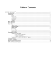
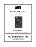
Radio Interface
Model MFJ-5124K/Y
INSTRUCTION MANUAL
CAUTION: Read All Instructions Before Operating Equipment !
MFJ ENTERPRISES, INC.
300 Industrial Park Road
Starkville, MS 39759 USA
Tel: 662-323-5869 Fax: 662-323-6551
VERSION 0A
COPYRIGHT
200 5 MFJ ENTERPRISES, INC.
MFJ-5124K/Y Radio Interface
Instruction Manual
Contents
Introduction............................................................................................................ 1
Front Panel...................................................................................................... 1
To Tuner .................................................................................................. 1
Power....................................................................................................... 1
To Radio .................................................................................................. 1
Jumper Settings............................................................................................... 2
Kenwood Radio Interface ...................................................................................... 2
Connections .................................................................................................... 3
Operation ........................................................................................................ 3
Yaesu Radio Interface............................................................................................ 4
Connections for FT-100, FT-857 and FT-897................................................ 4
Connections for FT-847.................................................................................. 4
Operation ........................................................................................................ 5
Technical Assistance.............................................................................................. 5
Schematic............................................................................................................... 6
© 2005 MFJ Enterprises, Inc.
i
MFJ-5124K/Y Radio Interface
Instruction Manual
THIS PAGE IS LEFT BLANK INTENTIONALLY
ii
© 2005 MFJ Enterprises, Inc.
MFJ-5124K/Y Radio Interface
Instruction Manual
Introduction
The MFJ-5124 Radio Interface main unit contains all the electronics that allows
users of AT-300 compatible Kenwood transceivers and certain Yaesu
transceivers with CAT system to connect to the MFJ-991, MFJ-993 and MFJ994 IntelliTuner™ Automatic Antenna Tuners. With this interface, DC power
to the radio interface and the tuner is supplied by the radio, except FT-847.
Uses of appropriate cable and selecting the interface protocol via internal
jumpers allow the interface to connect to the various Kenwood and Yaesu
radios. The radio interface allows one button tuning operation.
Front Panel
TO TUNER
POWER
MFJ-5124
TO RADIO
Radio Interface
•
To Tuner: The 3.5 mm stereo phone plug connects to the tuner’s RADIO
INTERFACE jack, and the 2.1 × 5.5 mm coaxial plug connects to the
tuner’s POWER jack.
•
Power: Accepts a standard 2.1 × 5.5 mm coaxial plug with positive center
and negative sleeve. The tuner requires 12 volts DC at up to 1 amp. The
use of a regulated supply is not mandatory but is recommended for best
performance. An optional 12 volts DC 1.5 amp power supply, the MFJ1316, is available from MFJ Enterprises, Inc.
Most radios provide +13.8 volts through the radio’s tuner port (Kenwood
AT/ACC and Yaesu CAT ports) to the TO RADIO jack, so the POWER
jack connection is rarely used. If the radio’s tuner port does not have a
power connection, such as the Yaesu FT-847, then connect a power supply
to this connector. If the radio’s tuner port has a power connection but
cannot supply one amp of current, then remove the internal jumper JP3 and
connect a power supply to this connector. Check your radio’s operating
manual.
WARNING:
•
Do not apply voltages greater than 18 volts to this
unit, or permanent damage to the unit and the tuner
may result.
To Radio: Accepts an 8-pin modular plug that connects the radio interface
to a Kenwood AT/ACC or Yaesu CAT port. Use proper cable for the
various radios.
© 2005 MFJ Enterprises, Inc.
1
MFJ-5124K/Y Radio Interface
Instruction Manual
Jumper Settings
Two jumpers, JP1 and JP2, inside the MFJ-5124 are used to select the radio to
interface with. To change these jumper settings:
1.
Disconnect the MFJ-5124 from the radio and the tuner.
2.
Open the MFJ-5124 case by removing the two screws on the bottom.
3.
Configure jumpers JP1 and JP2 according to the following table to
select the radio to interface with.
JP1
JP2
A
A
A
B
A
C
To Interface
Kenwood (auto detected tuner)
such as TS-570S, etc.
Kenwood (menu enabled tuner)
such as TS-450S, TS-690S, etc.
Reserved for future use.
B
A
Yaesu FT-857, FT-897
B
B
Yaesu FT-100
B
C
C
A
C
C
B
C
†
‡
Using
MFJ-5124K
(6-pin molex)
MFJ-5124K
(6-pin molex)
MFJ-5124Y1
(8-pin mini DIN)
MFJ-5124Y1
(8-pin mini DIN)
Reserved for future use.
MFJ-5124Y2
(DB-9)
Yaesu FT-847
Reserved for future use.
Reserved for future use.
† MFJ-5124K factory default.
‡ MFJ-5124Y factory default.
4.
Close the MFJ-5124 case and secure with the two screws.
5.
Connect the MFJ-5124 to the radio and the tuner.
Kenwood Radio Interface
The MFJ-5124K radio interface allows users of AT-300 compatible Kenwood
transceivers to connect to the MFJ-991, MFJ-993 and MFJ-994 IntelliTuner™
Automatic Antenna Tuners. With this interface, DC power is supplied by the
radio and control signals are connected between the radio and the tuner. The
operator can then control the tuner with a single push of the [AT TUNE] button
on the front panel of the radio.
2
© 2005 MFJ Enterprises, Inc.
MFJ-5124K/Y Radio Interface
Instruction Manual
Connections
1.
Insert the 3.5 mm stereo phone plug into the tuner’s RADIO
INTERFACE jack.
2.
Insert the 2.1 x 5.5 mm coaxial power plug into the tuner’s POWER
jack.
3.
Insert the 8-pin modular plug into the MFJ-5124’s TO RADIO jack.
4.
Important: Make sure the DC power to the radio has been turned off.
The radio does not fuse the DC power to the tuner, and damage to the
radio can occur if the interface’s power connection comes in contact
with ground.
5.
Connect the 6-pin molex connector to the mating 6-pin molex
connector, marked as AT or ACC, on the back of the Kenwood radio.
6.
Push the [POWER] button on the tuner to the in position. When the
radio is powered on, the tuner will also power on.
7.
Some Kenwood radios automatically check to see if an external
antenna tuner is connected during power on, such as the TS-570S (set
jumper JP2 to the A position). This is the factory default setting. If
both needles on the MFJ tuner keep bouncing (TURN ON RADIO
appears on the MFJ-993) and do not go away, then move jumper JP2 to
the B position.
For other Kenwood radios, the External Antenna Tuner menu in the
radio menu system must be enabled, such as the TS-450S and the TS690S (set jumper JP2 to the B position). If the MFJ tuner switches to
bypass mode during power on, then move jumper JP2 to the A position
because the radio is checking for a tuner presence during power on.
Refer to your radio’s operating manual for accessing the menu system
and preparing the AT-300 operation.
Operation
The operation of the MFJ-5124K radio interface is similar to the operation of the
AT-300 described in the Kenwood radio user’s manual. Press and hold the [AT
TUNE] button on the radio for one second to start the tuning process. The radio
will automatically switch to CW mode, transmit a 10-watt carrier, and start the
tuning process. When the tuning process is completed, the radio will stop
transmitting, return to its previous mode and power setting. Press the [AT
TUNE] button on the radio briefly will place the tuner into bypass mode (some
Kenwood radios, such as the TS-690S, do not have this bypass function).
Note the [TUNE] button on the tuner will not operate the radio interface.
© 2005 MFJ Enterprises, Inc.
3
MFJ-5124K/Y Radio Interface
Instruction Manual
Yaesu Radio Interface
The MFJ-5124Y1 radio interface allows users of certain Yaesu transceivers that
have an 8-pin mini DIN CAT port, such as the FT-100, FT-857 and FT-897, to
connect to the MFJ-991, MFJ-993 and MFJ-994 IntelliTuner™ Automatic
Antenna Tuners. The MFJ-5124Y2 radio interface connects to Yaesu
transceivers that have a DB-9 CAT port, such as the FT-847. With this
interface, DC power (except FT-847) is supplied by the radio and control signals
are connected between the tuner and the radio. The operator can then control
the tuner and the radio with the [TUNE] button on the front panel of the tuner.
Connections for FT-100, FT-857 and FT-897
1.
Insert the 3.5 mm stereo phone plug into the tuner’s RADIO
INTERFACE jack.
2.
Insert the 2.1 x 5.5 mm coaxial power plug into the tuner’s POWER
jack.
3.
Insert the 8-pin modular plug into the MFJ-5124’s TO RADIO jack.
4.
Important: Make sure the DC power to the radio has been turned off.
The radio does not fuse the DC power to the tuner, and damage to the
radio can occur if the interface’s power connection comes in contact
with ground.
5.
Connect the 8-pin mini DIN connector to the mating 8-pin mini DIN
connector, marked as CAT, on the back of the radio. The FT-100 has
the DIN connector at the end of a pigtail.
6.
Push the [POWER] button on the tuner to the in position. When the
radio is powered on, the tuner will also power on.
7.
The CAT/Tuner/Linear menu in the radio menu system should be set to
CAT. The CAT baud rate should be 4800 baud. ATAS (if available)
should be set to OFF. Some radios may need to be powered off and
then on for the changes to take place. Refer to your radio’s operating
manual for accessing the menu system.
Connections for FT-847
4
1.
Insert the 3.5 mm stereo phone plug into the tuner’s RADIO
INTERFACE jack.
2.
Insert the 2.1 x 5.5 mm coaxial power plug into the tuner’s POWER
jack.
3.
Insert the 8-pin modular plug into the MFJ-5124’s TO RADIO jack.
© 2005 MFJ Enterprises, Inc.
MFJ-5124K/Y Radio Interface
Instruction Manual
4.
Important: Make sure the DC power to the radio has been turned off.
The radio does not fuse the DC power to the tuner, and damage to the
radio can occur if the interface’s power connection comes in contact
with ground.
5.
Connect the DB-9 connector to the mating DB-9 connector, marked as
CAT, on the back of the radio.
6.
The FT-847 does not have a DC power connection on its CAT port.
Connect a 12 volts DC 1 amp power supply, such as the MFJ-1316, to
the MFJ-5124’s POWER jack. The tuner should be powered on before
the radio.
7.
The CAT/Tuner/Linear menu in the radio menu system should be set to
CAT. The CAT baud rate should be 4800 baud. ATAS (if available)
should be set to OFF. Some radios may need to be powered off and
then on for the changes to take place. Refer to your radio’s operating
manual for accessing the menu system.
Operation
The operation of the MFJ-5124Y radio interface is simple. Press and hold the
[TUNE] button on the tuner for 0.5 to 2 seconds to start the tuning process. The
radio will switch to AM mode, transmit a carrier, and start the tuning process.
When the tuning process is completed, the radio will stop transmitting and
return to its previous mode. Press the [TUNE] button on the tuner briefly will
place the tuner into bypass mode.
Note the [TUN] button on the radio will not operate the radio interface.
Technical Assistance
If you have any problem with this unit first check the appropriate section of this
manual. If the manual does not reference your problem or your problem is not
solved by reading the manual, you may call MFJ Technical Service at 662-3230549 or the MFJ Factory at 662-323-5869. You will be best helped if you have
your unit, manual and all information on your station handy so you can answer
any questions the technicians may ask.
You can also send questions by mail to MFJ Enterprises, Inc., 300 Industrial
Park Road, Starkville, MS 39759; by facsimile (FAX) to 662-323-6551; or by
email to [email protected]. Send a complete description of your
problem, an explanation of exactly how you are using your unit, and a complete
description of your station.
© 2005 MFJ Enterprises, Inc.
5
MFJ-5124K/Y Radio Interface
Instruction Manual
Schematic
6
© 2005 MFJ Enterprises, Inc.
LIMITED 12 MONTH WARRANTY
MFJ Enterprises, Inc. warrants to the original owner of this product, if manufactured by
MFJ Enterprises, Inc. and purchased from an authorized dealer or directly from MFJ
Enterprises, Inc. to be free from defects in material and workmanship for a period of 12
months from date of purchase provided the following terms of this warranty are satisfied:
1. The purchaser must retain the dated proof-of-purchase (bill of sale, canceled check, credit
card or money order receipt, etc.) describing the product to establish the validity of the
warranty claim and submit the original or machine reproduction of such proof of purchase to
MFJ Enterprises, Inc. at the time of warranty service. MFJ Enterprises, Inc. shall have the
discretion to deny warranty without dated proof-of-purchase. Any evidence of alteration,
erasure, or forgery shall be cause to void any and all warranty terms immediately.
2. MFJ Enterprises, Inc. agrees to repair or replace at MFJ's option without charge to the
original owner any defective product under warrantee provided the product is returned
postage prepaid to MFJ Enterprises, Inc. with a personal check, cashiers check, or money
order for $7.00 covering postage and handling.
3. This warranty is NOT void for owners who attempt to repair defective units. Technical
consultation is available by calling the Service Department at 662-323-0549 or the MFJ
Factory at 662-323-5869.
4. This warranty does not apply to kits sold by or manufactured by MFJ Enterprises, Inc.
5. Wired and tested PC board products are covered by this warranty provided only the wired
and tested PC board product is returned. Wired and tested PC boards installed in the owner's
cabinet or connected to switches, jacks, or cables, etc. sent to MFJ Enterprises, Inc. will be
returned at the owner's expense unrepaired.
6. Under no circumstances is MFJ Enterprises, Inc. liable for consequential damages to person
or property by the use of any MFJ products.
7. Out-of-Warranty Service: MFJ Enterprises, Inc. will repair any out-of-warranty product
provided the unit is shipped prepaid. All repaired units will be shipped COD to the owner.
Repair charges will be added to the COD fee unless other arrangements are made.
8. This warranty is given in lieu of any other warranty expressed or implied.
9. MFJ Enterprises, Inc. reserves the right to make changes or improvements in design or
manufacture without incurring any obligation to install such changes upon any of the
products previously manufactured.
10. All MFJ products to be serviced in-warranty or out-of-warranty should be addressed to:
MFJ Enterprises, Inc.
300 Industrial Park Road
Starkville, Mississippi 39759 USA
and must be accompanied by a letter describing the problem in detail along with a copy of
your dated proof-of-purchase.
11. This warranty gives you specific rights, and you may also have other rights which vary from
state to state.
MFJ ENTERPRISES, INC.
300 Industrial Park Road
Starkville, MS 39759 U.S.A.
MFJ-5124K/Y Manual
Version 0A
Printed In U.S.A.