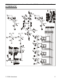
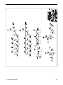
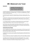
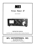
1
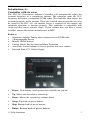
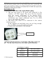
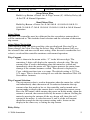
AMERITRON SDC-103 Automatic Screwdriver Antenna Controller for ICOM Radios INSTRUCTION MANUAL PLEASE READ THIS MANUAL BEFORE OPERATING THIS EQUIPMENT ! 116 Willow Road Starkville, MS 39759 USA 662-323-8211 Version 0A Printed in U.S.A. SDC-103 Automatic Screwdriver Controller (ICOM) Instruction Manual Introduction (A) Controller with six wires. The SDC-103 Screwdriver Antenna Controller will automatically adjust the resonant frequency of a screwdriver antenna. The controller reads the CI-V frequency data from a compatible ICOM radio. The controller then adjusts the resonant frequency of the antenna. Three pre-selected antenna positions can also be stored by the SDC-103. An antenna sensor is required for the counter and automatic operation to function properly. This controller is compatible with single and dual sensor antenna setups. If your antenna does not have a sensor installed, contact the antenna manufacturer or MFJ. Features • Automatic Antenna Tuning when connected to an ICOM radio • 3 Programmable Presets • Manual UP/DN buttons • Current Sensor Trip for Antenna/Motor Protection • Auto-Park: Lowers antenna to lowest position and zeros counter • Powered From 12V Vehicle Supply • Power: Push button switch powers the controller on and off. • Up: Moves the screwdriver antenna up. • Down: Moves the screwdriver antenna down. • Setup: Top bank of preset buttons. • Skip: Bottom bank of preset buttons. • Enter: Bottom bank of preset buttons. 2006 Ameritron 1 SDC-103 Automatic Screwdriver Controller (ICOM) Instruction Manual Installation There are seven wires that need to be connected in order for the controller to function properly. 1. The red wire needs to be fused and connected to the vehicle’s +12 VDC supply. The size of the fuse depends upon the current requirement of the antenna motor. Typically a 5 Amp slow-blow fuse will work. Some installations may require additional wire. Use 16 AWG wire to add additional length. 2. The black wire needs to be connected to the vehicle (station) ground. If the supplied red and black wires are not long enough, Use 16 AWG wire to add additional length. WARNING: Do not reverse the polarity of the Red and Black wires. Damage will occur to the controller. 3. 4. 5. The remaining four wires are connected to the antenna. The Green and Yellow wires are connected to the motor. The polarity of the motor connection determines the direction of the antenna. If the motor moves in the wrong direction, swap the wires or see the menu setup section for setting the correct direction. The Brown and White wires are the sensor wires and should be connected to the magnetic sensor on the antenna. There is no polarity associated with these wires. The following table shows the wire color and connections. Plug one end of the 6 foot mono cable supplied with the controller into the jack on the side of the controller. The opposite end should be plugged into the CI-V jack of ICOM radio. This jack is labeled as remote on most ICOM radios. Check the owner’s manual of the radio for further detail. A longer cable may be used if necessary for your installation Red Black Green Yellow Brown White CI-V Mono Cable 2006 Ameritron +12VDC Vehicle Ground Antenna Motor Antenna Motor Magnetic Sensor Magnetic Sensor SDC-103 to ICOM Radio 2 SDC-103 Automatic Screwdriver Controller (ICOM) Instruction Manual You will need to connect wires to each of these four wires, so that they will reach your screwdriver antenna. Use quality insulated wire for these extensions. The motor control wires should be no smaller than 18 AWG. the sensor wires should be no smaller than 24 AWG. Installation (B) Controllers that have the 4 pin Molex plug. 1. The red wire needs to be fused and connected to the vehicle’s +12 VDC supply. The size of the fuse depends upon the current requirement of the antenna motor. Typically a 5 Amp slow-blow fuse will work. Some installations may require additional wire. Use 16 AWG wire to add additional length. 2. The black wire needs to be connected to the vehicle (station) ground. If the supplied red and black wires are not long enough, Use 16 AWG wire to add additional length. 3. Connect the 4 pin Molex to the antenna. motor control Antennas that do not have a 4 pin plug. The plug can be cut off. Use the chart below for wire color and its function. CONTROL CABLE 2006 Ameritron RED MOTOR WIRE BLACK MOTOR WIRE GREEN SENSOR WHITE SENSOR 3 SDC-103 Automatic Screwdriver Controller (ICOM) Instruction Manual Take care and follow your antenna manufacturer’s suggestions about routing these wires for a mobile installation. Avoid routing control wires with the feed line. Make sure a RF choke is placed around the control lines at the antenna. The mono data cable should have an RF choke as well. WARNING: An RF choke must be placed around the control lines at the antenna. The Controller may be damaged if an RF choke is not used. MFJ recommends a choke to be placed on the data cable. Motor Operating Voltage This control unit is designed to operate with a screwdriver antenna that operates on 12 volts. Many antennas operate on only 3 or 4 volts, a Dropping Resistor can be used inline with the motor wires to bring the voltage down. Consult your antenna manual or manufacturer for the operating voltage. Important: Failure to adjust and operate your screwdriver antenna at the proper voltage will damage the antenna motor. If a dropping resistor is necessary, a good value to try is 5 Ω/10 Watts. This resistor will need to be placed inline on one of the motor control lines anywhere in between the MFJ-1924 and the antenna. If you are not sure whether or not this resistor is necessary for your antenna, try it and inspect the torque and speed of the motor. If the motor is too slow, reduce or eliminate the resistance. Use of 12 volts with a 3 or 4-volt antenna will result in failure of the motor. WARNING: Do not apply voltages greater than 18 volts to this unit, or permanent damage to the unit and antenna may result. Menu The table below lists the features and options of the MFJ-1924. Use this table and the following section to adjust these settings specific to your screwdriver antenna and its requirements for proper operation. Function Reset Auto Park Setup Menu Band Activate By: Hold Down button while powering up unit. Depress Up and Down simultaneously for 2 seconds. Press Setup Button while powering up unit. Press Skip Button while 2006 Ameritron Description Clears all memory positions Bottoms antenna and zeros the counter Allows setting the trip current, relay delay, and up features. Choose which bands are active for 4 SDC-103 Automatic Screwdriver Controller (ICOM) Instruction Manual Menu powering up unit. automatic antenna control Setup Menu Flow Hold Setup Button + Power On Trip Current (C) Relay Delay (d) Set UP Normal Operation Band Menu Flow Hold Skip Button + Power On 160 Off 80 Off 40 Off 30 Off 20 Off 17 Off 15 Off 12 Off 10 Off 6 Off Normal Operation Setup Menu The SDC-103 controller must be calibrated for the screwdriver antenna that it will be connected to. This includes band selection and the selection of the motor trip current. Setup Menu Navigation After entering setup, the setting and the value are displayed. Pressing Up or Down changes the value. Pressing the Select, Skip, or Enter buttons will save the selected value and move to the next setting. After the end is reached the last value is saved and the controller continues with normal operation. Trip Current This is shown in the menu with a “C” in the left-most digit. The remaining 3 digits will display the currently selected value. The trip current value is used to determine when the motor has stalled and immediately shuts the motor off. This feature protects the motor from damage if the antenna becomes stalled. The current is displayed as Cxxx, which translates into x.xx amps. The default setting is C075 or 0.75 amps. This is also the setting for use with the Ameritron SDA-100 Screwdriver Antenna. Trip Current Selection The trip current value is used to determine when the motor has stalled and immediately shuts the motor off. In order to determine the trip current value that needs to be set, the controller can be turned on in current mode to display the current that is read from the current sensor. Press the UP button while turning the power on.In this mode, when the antenna is moved, the current drawn by the motor is shown. Stalling the motor by moving the antenna all the way down will show the stall current of the motor. A value between ¼ and ¾ of the stall current should be enough for the trip current setting and is shown on the display in the same way as setting the trip current. Relay Delay 2006 Ameritron 5 SDC-103 Automatic Screwdriver Controller (ICOM) Instruction Manual This setting controls the amount of time the relays are reversed when the motor is stopped. When the motor is stopped, the relay that was moving the motor is deactivated and the opposite relay is activated for the duration set in the menu. The default setting is 20ms. The values range from 0ms – 200ms. UP This determines which button will move the antenna up. This can also be used to move the antenna correctly if the motor terminals are reversed. When UP is on the display, press the corresponding button (Up or Down), which moves the antenna up. This is then saved to memory. Pressing any other key will not make any changes and simply exit setup. Since this is the last setting in the setup menu. The controller will proceed with normal operation. Band Menu Navigation The Band Menu of the SDC-103 controller allows the user to activate the frequency bands that will be used for controlling the antenna. Follow the instructions below to activate/deactivate bands. Band Select Press the Skip Button while powering up unit. The controller display will show the current status of the 160 meter band (on/off). To change the status of this band press up to turn the band on or dn to turn the band off. When the setting is correct press Enter to continue to the next band. Repeat this process for each of the bands. Pressing Enter after the 6 meter band will save the settings and exit the menu. Note: For changes to be saved you must go through each of the bands. Frequency Menu Navigation This menu is used to program the upper and lower frequency limits for each band. The SDC-103 will use these limits to adjust the operating frequency of the antenna. Use the chart in the appendix of this manual to record the highest and lowest desired operating frequency for each amateur band activated in the above menu. 1. Press and hold the Enter button while turning on Power to the controller. The controller will move the antenna to the lowest position. When the lowest position is reached the controller should stop the motor if the current settings are adjusted properly (see the Trip Current section above). If the antenna extends outward instead of retracting turn the power off and see the UP section above to reverse the direction of travel. 2. If all settings are correct the controller will stop the antenna at the minimum height and display “0” then display “Con” or “nd”. “Con” indicates the controller is receiving data from the radio. “nd” indicates there is no data being received. If no data is 2006 Ameritron 6 SDC-103 Automatic Screwdriver Controller (ICOM) Instruction Manual received check the connection with your radio. Note: The radio must be powered on before the SDC-103. NOTE: If no data is sent to the controller from the radio the automatic features of the controller will not function. 3. 4. 5. 6. 7. The Lowest band / Highest operating frequency will be displayed if the settings are correct. Tune the VFO of the radio to the frequency you determined to be the highest operating frequency of the displayed meter band. Adjust the antenna using the up/dn buttons until the antenna is tuned at that frequency. Once the radio and antenna are tuned at the desired frequency press the Enter button to save the position. The controller should display the “band+L” for the lowest frequency on that band. Set the radio to the lowest frequency of the band you wish to operate and tune the antenna for resonance, minimum SWR. Press Enter to store the position and continue to the next band. This same procedure should be followed for each of the active bands selected. When the last low frequency is programmed the controller will display “Con.” Test your settings by changing the frequency of the radio. Use low power to verify an acceptable SWR is present before using full power. Saving Memory Positions Three antenna positions may be saved by the controller. To store an antenna position: a. Use the UP/DN buttons to tune the antenna. b. Press and hold Select, Skip, or Enter until the display reads done. Radio Settings The ICOM radio CI-V settings must be configured to the following: CIV Baud AT(AUTO) CIV ADD5E CIV TRN ON CIV 731OFF Operation 1. Power on your ICOM radio. 2. Power on your SDC-103. The controller should display “Con.” 3. Tune the frequency dial on your ICOM radio. The antenna should begin moving according to your settings. 4. When the antenna has reached the tuned position apply a low amount of power 5-10 watts, and verify that the antenna is tuned using an SWR meter either internal or external to your radio. Small adjustments may need to be made by pressing the up/dn buttons on the controller Fine 2006 Ameritron 7 SDC-103 Automatic Screwdriver Controller (ICOM) Instruction Manual tuning may be necessary if the antenna is not tuned correctly. This may be a very small adjustment. This can easily be done by pressing the up/dn buttons briefly. TECHNICAL ASSISTANCE If you have any problem with this unit first check the appropriate section of this manual. If the manual does not reference your problem or your problem is not solved by reading the manual, you may call MFJ Technical Service at 662-3230549 or the MFJ Factory at 662-323-5869. You will be best helped if you have your unit, manual and all information on your station handy so you can answer any questions the technicians may ask. You can also send questions by mail to MFJ Enterprises, Inc., 300 Industrial Park Road, Starkville, MS 39759; by facsimile (FAX) to 662-323-6551; or by email to [email protected]. Send a complete description of your problem, an explanation of exactly how you are using your unit, and a complete description of your station. 2006 Ameritron 8 SDC-103 Automatic Screwdriver Controller (ICOM) Instruction Manual SCHEMATIC 2006 Ameritron 9 SDC-103 Automatic Screwdriver Controller (ICOM) 2006 Ameritron Instruction Manual 10 SDC-103 Automatic Screwdriver Controller (ICOM) APPENDIX: Band 160M(H) 160M(L) 80M (H) 80M (L) 40M (H) 40M L 30M H 30M L 20M H 20M L 17M H 17M L 15M H 15M L 12M H 12M L 10M H 10M L 6M H 6M L Instruction Manual Frequency (MHz) 2006 Ameritron 11