1
Pages from User Manual
for
Speed Dome Camera
DomePTZ-dn1
www.allthings.com.au
2.OPERATION
The speed dome camera can be controlled remotely horizontal and vertical movement. It is controlled remotely from the
keyboard or controller through a serial connection to the RS-485 connector.
The speed dome camera will conduct a self-check after powered up and
“P:P-D2400,
ID:001,
V10”.
the monitor will display as following
The information will be disappeared after the self-check
is finished.(Protocol and ID code will be displayed according to the users’ choice)
Normal Function:
2.1 Pan/Tilt Function
The camera is capable of moving vertically and horizontally. The Pan/Tilt speed is variable for given amount of joystick
deflection.
2.2
Lens Function
2.2.1
Zoom Lens Function
Transform the view angle of the camera(zoom in / zoom out),press[TELE] or [WIDE] .
2.2.2
Focus Function
In some special circumstance, users need conduct focus manual, he can press [NEAR] or [FAR] to transform the focus.
2.2.3
Iris Function
In normal circumstance, iris is in auto mode. If users need to change the iris level, they can press [OPEN] or [CLOSE] to
adjust.
2.3
Preset Function
The speed dome camera is capable of going to 32 preset positions. Each is with its own P/T/Z and focus. When preset a
camera position, the P/T/Z and focus will be memorized for that position.
2.3.1
To set a preset position
First input"PRESET", and then input the number of preset position and press“ENTER”at the end.
[PRESET] + N + [ENTER],
N→the number of preset position: 1~ 32.
2.3.2
To call a preset position
When camera positions have been preset, you can enter a memorized camera position number.
[CALL] + N + [ENTER],
2.3.3
N→the number of preset position: 1~ 32.
To delete a preset position:
First input"PRESET",and then input the preset position number and press“OFF”at the end.
[PRESET] + N + [OFF],
2.4
N→the number of preset position which will be deleted.
Setting of the Pan scan between two points:
1) The dome device conduct auto Pan Scan between two preset positions.
2) Users can set the starting point by pressing “PRESET+52+ENTER” and set the ending point by pressing
“PRESET+53+ENTER”.
3) press “CALL+52+ENTER” to start Pan scan.
4) The dwell time of “starting point” and “ending point” of Pan scan is 4 seconds.
5) Stop it by operate “Pan”or “Tilt”.
6) You can cancel the point by pressing “PRESET+52+OFF”
2. 5
Operation instruction about the tour scan movement:
1) Auto point by point scan from preset point number 1 to number 16, if a certain point is not set or cleared,
that point will not be scan when “tour scan” is in progress.
2) The dwell time of preset point in tour is 4 seconds.
3) The defaulted tour function can be executed by inputting “CALL+51+ENTER”.
4) Stop it by operate “Pan”or “Tilt”.
www.allthings.com.au
2. 6
Setting of Home position :
This means the time duration for the dome device to return to the number 1 direction preset position when no-man
control occurs.
1) Start this function by pressing “CALL+54+ENTER”.
2) The time of returning to preset direction position number 1 can be set to 1 minute / 5 minutes / 10 minutes / 30
minutes / 60 minutes by pressing “CALL+55+ENTER” / “CALL+56+ENTER” / “CALL+57+ENTER” /
“CALL+58+ENTER” / “CALL+59+ENTER”.
3) Disable this function by pressing “PRESET+54+ENTER”.
2. 7
Intelligent three-dimension tour scan setting :
When the user is monitoring with manual Pan scan, he only needs to maintain the scan direction to continue
the scan monitoring, and then press “CALL+50+ENTER” to auto continue the manual Pan scan action.
2. 8
Six groups of programmable tour:
It has the functions of tour setting and call out, as well as saving the directional used programmed tour. Each
group of tour contains 12 preset positions, the running speed and dwell time of which can be set and the data will not
be lost when the power is off.
2.9 Integrated swivel and tilt movement
1)Pan rotation is 360º endless; Tilt movement is 20~90º,by using the key boards speed can be adjustable from 0.5~
30º/s.
2) The low speed running is stable with ultra-low noise and without image shake.
3) by pushing down the Joystick till the point of 90º the camera will auto lift up 10 degree. Monitoring all directions
with ±2º precision.
3.0 OSD MENU exit
There are three ways to exit the menu after you enter the menu by pressing
“CALL+64+ENTER”
the first way is by pressing “PRESET+64+ENTER”, the second way is by using joystick to keep turning
left for about 3 seconds , the third way is also by using joystick,but turn left for several tmes..
3.1
Special Function—Power-off Protection
When the camera is under scan or cruise track, and power off occurs, the camera will save the state before the
power-off. When power is resupplied, the camera will continue to perform the scan or cruise track automatically under the
same state before power-off. Should scan or cruise track are not performed before power-off, the camera will stop at the
first preset position automatically.
3.2 Auxiliary Functions List
Operation
Preset + N + Enter
Preset + N + OFF
Call
+ N + Enter
Call
+ 50 + Enter
Call
+ 51 + Enter
Preset + 52 + Enter
Preset + 53 + Enter
Preset +52 + OFF
Call
+ 52 + Enter
Call
+ 54 + Enter
Preset + 54 + Enter
Call
+ 55 + Enter
Call
+ 56 + Enter
www.allthings.com.au
Function
Set the number N preset position (1≤N≤32)
Clear the number N preset position (1≤N≤32)
Call the number N preset position (1≤N≤32)
Auto Intelligent Tour Pan Scan
Auto cruise (preset position from No.1 to No.16)
Set the Starting Point of the Pan Scan between two points
Set the End Point of the Pan Scan between two points
Clear the Points of the Pan Scan between two points
Pan Scan between the two Seeting points
Auto Back Home ON
Auto Back Home OFF
Auto Back Home after 1 minute when Auto Back Home is ON
Auto Back Home after 5 minute when Auto Back Home is ON
Call
+ 57 + Enter
Call
+ 58 + Enter
Call
+ 59 + Enter
SHOT+N+ON+(TEL
E or WIDE)+OFF
SHOT+N+Enter
SHOT+N+OFF
(long press)
Auto Back Home after 10 minute when Auto Back Home is ON
Auto Back Home after 30 minute when Auto Back Home is ON
Auto Back Home after 60 minute when Auto Back Home is ON
Set the cruise tracks N
(1≤N≤6)
Call the cruise tracks N
(1≤N≤6)
Clear the cruise tracks N
Operation
Function
(1≤N≤6)
(Only For 15-CD51PTZ)
Call
+ 64 + Enter
Camera Menu ON
Preset
+ 64 + Enter
Camera Menu OFF
Call
+ 65 + Enter
Backlight Compensation ON
Preset
+ 65 + Enter
Backlight Compensation OFF
Call
+ 66 + Enter
Digital Zoom ON
Preset
+ 66 + Enter
Digital Zoom OFF
Call
+ 67 + Enter
Camera Preset ON
Call
+ 68 + Enter
Image Mirror ON
Preset
+ 68 + Enter
Image Mirror OFF
Call
+ 69 + Enter
Image Up-side down ON
Preset
+ 69 + Enter
Image Up-side down OFF
Call
+ 70 + Enter
Image Negative
Preset
+ 70 + Enter
Image Positive
Call
+ 71 + Enter
Image Freeze ON
Preset
+ 71 + Enter
Image Freeze OFF
Call
+ 72 + Enter
Color Bar ON
Preset
+ 72 + Enter
Color Bar OFF
Call
+ 73 + Enter
Preset OSD ON
Preset
+ 73 + Enter
Preset OSD OFF
Call
+ 74 + Enter
Camera Menu OSD in Chinese
Call
+ 75 + Enter
Camera Menu OSDin English
Call
+ 76 + Enter
Camera Menu OSD in Japenese
WIDE
Zoom Wide
TELE
Zoom Tele
FAR
Focus Far
NEAR
Focus Near
OPEN
IRIS Open
CLOSE
IRIS Close
www.allthings.com.au
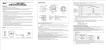
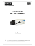
3.ID SETTING
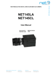
ID of this speed dome can be set by the switch with 8 codes. Below is the detail of setting ID code:
(Turn the power off when setting, and restart the device after revision).
The figure shows: Address of the dome device: No. 1
(Please refer to detailed parameter in next chapter)
Set address for dome
This switch “S2” (ID NUMBER setting) located on PCB in the dome device.
4.PROTOCOL SETTING
Protocol of this speed dome can be set by the switch with 3 protocol codes. Below is the detail of setting protocol code:
Note:All setting must be operated after power off.
Power on until it is completed.!
The N0.4,N0.5 and No.6 of the switch “S1” is help to set the protocol :
When the N0.4 is set to “OFF” and the N0.5 is set to “OFF” and the N0.6 is set to “ON” ,the protocol is PELCO-D,the
baud rate is 2400bps.
When the N0.4 is set to “OFF” and the N0.5 is set to “ON” and the N0.6 is set to “OFF” ,the protocol is PELCO-P,the
baud rate is 4800bps.
When the N0.4 is set to “OFF” and the N0.5 is set to “ON” and the N0.6 is set to “ON” ,the protocol is PELCO-P,the
baud rate is 9600bps.
When the N0.4 is set to “OFF” and the N0.5 is set to “OFF” and the N0.6 is set to “OFF” ,the system judge the
protocol from the keyboard automatically(only support the PELCO-D/2400bps,PELCO-P/4800bps,PELCO-P/9600bps).
www.allthings.com.au
5. CONSTRUCTION
5.1 Dome Ceiling Mount
5.2 Cable
Dome Wall Mount (NOT AVAILABLE)
Note: When powered up, the camera performs a self-check for about 20 seconds (including one panning, tilting, zooming
and focusing operation). During the period, control operations are not executed.
www.allthings.com.au
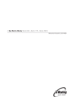
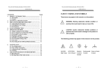
7. CONNECTION OF RS485 BUS AND TERMINATION RESISTOR
(1)
Characteristics of RS485 Bus
As specified by RS485 standards. RS485 Bus is of half duplexed data transmission cables with characteristic
impedance as 120. The maximum load is 32 unit loads (including main controller and controlled equipment.)
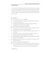
(2) The RS485standarda require a daisy-chain connection between the equipment. There must be termination
resistor with 120 ohms impedance at both ends of the connection (refer to the following FIGURE)
(3) Problem in Practical Connection
In some circumstances user adopts a star configuration in practical connection. The termination resistors must be
connected to the two equipments (No. 6 and No. 1) that are farthest away from each other. But the connection does not meet
the RS485 standards.
1 2 0Ω
1#
C ontrol
1 2 0Ω
1 2 0Ω
6#
12#
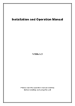
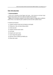
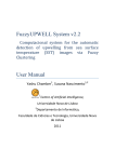
When the cable distance of equipments are far away, some problems, such as signal reflection, anti-jamming ability
decrease are easily occur and result in the reliability decline of control signal. The resulted phenomena represent that the
camera is out of control completely or interruptedly or operates automatically and fails to stop, etc. In such circumstances
the factory recommends the RS485 Signal Distributor. The distributor can change the star configuration connection to the
mode of connection stipulated in the RS485 standards. The new connection achieves reliable data transmission.
RS485 Distributor
Each connection can connect 32 terminations, and practical connections must be considered.
www.allthings.com.au
8. INSTALLATION
8.1 Standard Installation
8.11 Seting Protocol and ID
(1)Disassemble the glass Hood and the black Hood in the dome housing by the screwdriver, change the switch “S1” to
set the ID of this speed dome and change the switch “S2” to set the protocol. The detail can see the 3.ID SETTING and
the 4.PROTOCOL SETTING
(2) Assemble the glass Hood and the black Hood in the dome housing again.
8.12 Install the Thread Connector
Lock the screws (4*12 type) into the thred connector. (fig.1)
Fig.1
8.13 Install the Speeddome mounting base
(1) Cut three holes in the ceiling.
(2) Put the cable through the Speeddome mounting base.(Fig.2)
(3) Let the RJ45 left about 15mm from the Speeddome mounting base. (Fig.3)
(4) Mout the Speeddome mounting base with three screws (4*35 type) on the ceiling.
(5) Connect the RJ45 with the bottom of the speed dome.
(6) Put the waterproof film into the bottom of the speed dome closely.
(7) Put the thread connector into the Speeddome mounting base and then turn left,lock the screws of the
thred connector to connect the Speeddome mounting base closely (Fig.4).
Fig.2
www.allthings.com.au
Fig.3
Fig.4
www.allthings.com.au
APPENDIX : MENU OF CAMERA MODULE
How to enter the menu of Camera module?
1.
2.
To execute the order CALL+64+ENTER into the menu.
Then you will see the menu of module
Main Menu ( Page 1. )
S E T U P
M E N U
Î W H
I
T E
I
I
S
R
A G C ・
(
1
/
3
)
/
3
)
B A L A N C E
S E N S
B A C K L
I
G H T
E N H A N C E R
Z O O M ・
H
/
V
T
I
T L E
F O C U S
R E V E R S E
P R E S E T
Main Menu ( Page 2. )
S E T U P
M E N U
Î M O T
I
O N
P O S
I
T
I
(
2
D E T E C T
O N
G A M M A
P O W E R
O N
M A S K
O S D
Z O O M + A F
L A N G U A G E
C O M M ・
I
D
Main Menu ( Page 3. )
S E T U P
M E N U
Î C R O S S
L I
N E
F R E E Z E
P O S I
www.allthings.com.au
/
N E G A
(
3
/
3
)
Sub Menu
White Balance
W H
I
T E
Î C O L O R
B A L A N C E
O F F
O N
Î A U T O
W B
G A
I
N
Î A T W
R
-
-
-
■
-
-
B
A W B
R
-
-
-
■
-
-
B
Î R
-
Y
-
-
-
-
■
-
-
-
B
-
Y
-
-
-
-
■
-
-
-
This is used to control the color ON/OFF and white balance and the gain rate of RED & BLUE color.
1. 「COLOR」selector:OFF is monochrome image,ON is normal color image,AUTO is at low light
AGC up, display image will be auto change to monochrome image.
2. 「WB」White balance control:ATW is Auto trace white balance,can be adjust offset level. AWB is
One push white balance. Push [menu] key「AWB」will start flicker, until flicker stop it will lock the
current color temperature at the same time.
3. 「GAIN」:The gain rate of R-Y & B-Y can be adjusted separately.
IRIS
I
R
I
S
Î P E A K
Î O F F
O N
A L C
-
-
-
-
-
P
-
-
-
■
-
-
-
-
-
-
■
-
-
-
-
-
■
-
-
-
Î A U T O
F
A E S
A ■
I
X
A U T O
Î F
I
X
-
O F F
This is used to control the iris & shutter speed of the lens. It included 3 items “PEAK”, “ALC”, “AES”.
1.「PEAK」is used to control the reaction of auto iris, which is based on the average light of picture
signal or the light rate of the peak.
2.「ALC」is used to select AUTO or FIX. Adjust IRIS level.
3.「AES」is used to select electronic shutter be AUTO or FIX function, at AUTO mode can be adjust
AES level,at FIX mode can be selector shutter speed at below, [OFF],[1/100sec],[1/120sec],
[1/250sec], [1/500sec],[1/1000sec],[1/2000sec],[1/4000sec],[1/10000sec]
www.allthings.com.au
AGC・SENS
A G C
▪
S E N S
Î A G C
S E N S
A U T O
-
-
-
■
-
-
-
A U T O
■
-
-
-
-
-
-
This is used to select「AGC」and「SENS」function.
1.「AGC」:To adjust auto gain control, 0dBb~24dB 9 steps adjustable.
2. 「SENS」:For low light application: 0 Frame,6 Frame,12 Frame,16 Frame,18 Frame,22 Frame,
24 Frame,30 Frame,36 Frame, 9 steps adjustable.
BACKLIGHT
B A C K L
I
G H T
Î O F F
O N
Î A R E A
S E N S
L O W -
-
-
-
■
-
-
-
H
I
This is used to control “BLC” (Back Light Compensation),
1.「BLC」ON / OFF selector. Selector「ON」has 2 sub-items:「AREA」,「SENS」.
2.「AREA」: 48 BLC zones can be set separatly. According to the mask area (BLC zone) signal to
decide the iris and shutter speed.
3.「SENS」:Is used to enhance the BLC effect.
ENHANCER
E N H A N C E R
H
▪
G A
I
N
-
-
-
-
-
-
■
-
-
-
V
▪
G A
I
N
-
-
-
-
-
-
■
-
-
-
This is used to enhance the compensation of the picture quality.
1.「H • GAIN」:Horizontal Compensation
2.「V • GAIN」:Vertical Compensation
www.allthings.com.au
ZOOM・FOCUS
Z O O M ▪
F O C U S
Î D
T A L
I
G
I
Z O O M
O F F
Z O O M
S P E E D
-
-
-
■
-
-
F O C U S
S P E E D
-
-
-
■
-
-
W I
D E
Z O O M
T E L E
F O C U S
Î M A N U A L
I
N F
N E A R
A U T O
This is used to control the montion of the lens, included “Digital ZOOM” ON/OFF and times set
function.
1.「Digital ZOOM」selector:OFF、X2、X4、X6、X8、X10.
2.「ZOOM Speed」:Set the speed of the zoom.
3.「FOCUS Speed」:Set the speed of focus.
4.「ZOOM」:Lens ZOOM adjust WIDE / TELE
5.「FOCUS」:AUTO / MANUAL setting
H/V REVERSE
H
/
V
Î H
▪
R E V E R S E
R E V E R S E
Î O F F
O N
V
▪
R E V E R S E
Î O F F
O N
This is used to select image「Horizontal Reverse」and「Vertical Reverse」function.
1.「H.REVERSE」:Horizontal Reverse (Mirror) ON/OFF
2.「V.REVERSE」:Vertical Reverse (Up-side down) ON/OFF
TITLE
T
I
Î 0
T L E
1
2
3
4
5
6
7
8
9
A B C D E F G H
I
J K L M
N O P Q R S T U V W X Y Z
a b c d e
f
g h
i
n o p q
r
s
t
u
v w x
□ : ; '
"
.
,
< >
U P
D O W N
www.allthings.com.au
j
(
k
)
l m
y
z
[
]
{
}
┌ ┘ ─
*
/
This is used to set up the ID figures & position on the screen. (Title setting)
1.TITLE start position selector.
2.TITLE Character selector.
3.TITLE display position UP or DOWN selector.
PRESET
P R E S E T
Î O F F
O N
I
N
I
T
I
A L
O F F
Î O N
P H A S E
Î O F F
O N
─
-
-
-
-
-
-
■
-
-
-
-
+
This is used to select the camera go back to “PRESET”, “INITIAL”, “PHASE” condition
1.「PRESET」:Set to ON camera will be reset and set to default data.
2.「INITIAL」select:Set to ON lens is action,Set to OFF lens is not action.
3.「PHASE」adj select:Set to OFF ext-sync is disable,Set to ON ext-VD sync is enable,(EXT-VD
signal must be input)
4. PHASE set to ON sync-phase adjustment.
MOTION DETECT
M O T
I
O N
D E T E C T
Î O F F
O N
A R E A
T
I
M E
S E N S
1
0 S E C
Î 3
0 S E C
6
0 S E C
L O W
This is used to select the montion detcet function.
1. Motion detect ON / OFF select.
2. Motion detects area select.
3. Motion detects output time select.
4. Motion detect sensitive adjust.
www.allthings.com.au
-
-
-
■
-
-
-
HI
POSITION
P O S
I
T
I
O N
A L A R M
N O =
F R E E Z E
0
Î O F F
O N
P O S
I
T
I
Î N O =
1
O N
Z O O M
S P E E D
-
-
F O C U S
S P E E D
-
-
Z O O M
W I
F O C U S
I
D E
N F
-
■
-
-
-
■
-
-
T E L E
N E A R
This is used to set「ALARM-IN」function,either「ALARM POSITION」or「IMAGE FREEZE」.
1.「ALARM NO.」:Set alarm position(1~64),if set to (0) alarm position is not enable.
2.「Freeze」:Set ON mode,「ALARM-IN」is freeze trigger input.
3.「POSITION」:The alarm position have 64 steps (position) can be programed.
By this program,the zoom & focus may go to the exactly position where is programed.
GAMMA
G A M M A
Î T Y P E 1
T Y P E 2
This is used to select the camera gamma correction.
「GAMMA」select:TYPE-A gamma is 0.45, TYPE-B gamma is 1.0
POWER ON
P O W E R
O N
Î B L U E
B A C K
O F F
Î O N
P O S
I
T
I
O N
Î O F F
O N
N O =
1
This is used to select the camera power on state.
1.「BLUE BACK」
:Set to OFF camaer power on initial is normal display, Set to ON camaer power on
initial is display blue back.
2.「POSITION OFF」:Camera power on lens position is current position.
3.「POSITION ON」:Camera power on lens position is go to the designation position(1~64).
www.allthings.com.au
MASK
M A S K
Î P O S
I
T
M A S K
I
O N
N O =
N O =
1
1
Î O F F
O N
Î H
-
S T A R T =
2
0
H
-
E N D
=
2
0
V
-
S T A R T =
2
0
V
-
E N D
2
0
=
C O N N E C T Î O F F
O N
This is used to select mask area size and position for each setable lens position.
1. Lens position no. select(1~64)
2. MASK NO. select(1~4)
3. MASK area display ON / OFF select.
4. Hor. direction start position.
5. Hor. direction end position.
6. Ver. direction start position.
7. Ver. direction end position.
8.ZOOM action to link mask area, ON / OFF select.
OSD
O S D
Î P O S
I
T
I
M O T
I
O N
O N
O F F
Î O N
Î O F F
O N
Z O O M ▪ M A G
Î O F F
O N
This is used to select on screen display ON / OFF select.
1. POSITION NO. display ON / OFF select.
2. MONTION action display ON / OFF select.
3. ZOOM times display ON / OFF select.
ZOOM+AF
Z O O M + A F
Î Z O O M + A F
Î O F F
O N
A F
S L E E P
Î O F F
O N
www.allthings.com.au
This is used to select an occasion for auto focus action.
1. ZOOM stops time execute lens focus once, action OFF / ON select.
2. AF Sleep function ON / OFF select.
(As show screen stillness about 5 minutes cameras come into AF Sleep mode namely, as screen has
bigger change time come back again act for normal mode namely.)
LANGUGE
L A N G U A G E
Î E N G L
C H
I
I
S H
N E S E
J A P A N E S E
This is used to select OSD manu display language.
OSD display language select, ENGLISH / CHINESE (Simp.) / JAPANESE
COMM・ID
C O M M ▪
I
D
Î C O M M ▪
I
D =
M O D E
1
Î 1
:
1
1
:
N
This is used to select communcation ID and mode.
1. Communication ID number's set.(Enactment supply controller identification camera uses ID
number.)
2. MODE choice
1:1 : One controller to control one Camera.
1:N : One controller to control many Cameras.
CROSS LINE
C R O S S
L
I
N E
Î O F F
O N
This is used to select the cross line display ON / FF.
Cross line ON/OFF select,set ON cross line display,set OFF cross line is hidden.
www.allthings.com.au
FREEZE
F R E E Z E
Î O F F
O N
This is used to set「IMAGE FREEZE」.
「Freeze」:Set ON mode,「ALARM-IN」is freeze trigger input.
POSI / NEGA
P O S
I
/
Î P O S
I
N E G A
N E G A
This is used to select image「Positive」and「Negative」function.
「POSI/NEGA」:Image positive & negative select.
www.allthings.com.au