1
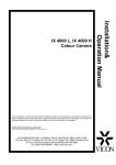
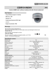
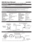
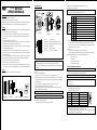
CCD CAMERA
DESCRIPTION OF PARTS:
WAT-535EX
Shutter speed selector: Nine different manual and electronic shutter speed settings. (0 to 9)
Shutter speed is set to 9 (OFF) upon shipment.
NOTE: Installed directly under fluorescent or incandescent lighting may cause flickering on the monitor. In order to reduce
or eliminate this interference, set the SHUTTER speed to the FL setting.
OPERATION MANUAL
INTRODUCTION:
Thank you for choosing our WAT-535EX CCD camera.
Watec hopes that both the quality and design satisfy your requirements.
Before proceeding to install or operate the WAT-535EX, please read the contents of the Operation Manual thoroughly to ensure
proper usage and understanding of our product. For future reference we also advise safe-keeping of this manual.
CAUTIONS:
1. Use only the AD-901 or equivalent power adaptor for the WAT-535EX. (Power supplied without voltage stabilization and/or
voltage range maintained at ±10% 12V DC may cause damage.)
2. Do not expose the WAT-535EX to wetness or high moisture conditions. The WAT-535EX is designed and approved for
indoor use only. For outdoor use or outdoor like conditions, we recommend that a special camera housing is installed for
adequate protection.
3. Avoid striking the unit with hard objects or dropping the unit.
4. Do not disassemble and/or modify the WAT-535EX, or its component parts or accessories. Watec can not be held responsible
for equipment operation failure or any damage and/or trouble caused by such action.
5. Do not install the WAT-535EX near heat sources, such as radiators or heating air ducts, or in a place subject to direct sunlight
※, excessive dust, mechanical vibration or shock.
6. When installing the WAT-535EX in an industrial or commercial environment (i.e., within equipment housing, near other
electronic device, etc.) make sure to avoid any strong electromagnetic field, otherwise, the video output may be distorted and
monitor clearness compromised.
7. Do not connect any power supply directly to the terminal of the VIDEO OUT/SYNC IN connector. This may cause damage.
8. When a cable operation system is being used (video signal/power coaxial cable transmission), check the specifications of
your monitor for proper connection to the video signal terminal of the camera.
9. Do not make connections and/or operate the WAT-535EX with wet hands.
Should the WAT-535EX not work properly, switch off the power and then, check all the required connectors, power cable,
and if the video cable is properly connected. ※ Sunlight shining directly onto the camera lens may cause damage to the CCD.
CONTENT:
Using the contents figures below. Check to make sure all parts are present before use.
Lens Mount Cap
WAT-535EX
DC Plug
Iris Connector
Operation Manual
<Front View>
<Side View>
①CCD
③Iris level control
⑤Auto iris socket
⑦VIDEO OUT
⑨SYNC. IN
Shutter SW
<Back View>
②CS lens mount
④Hexagonal focusing adjustment screws (X3)
⑥Tripod mounting screw holes (upper and lower)
⑧POWER IN
GAIN CONTROL
Function SW (Internal View)
<Internal View>
①CCD (front face): The light receiving face of the CCD camera.
NOTE: 1. Handle the CCD and lens with special care.
2. Always attach the lens cap so as to protect the lens and/or the CCD from contamination or damage.
3. Dirt, water or oil deposits on either will cause an unclear picture on the monitor. Scratches will cause permanent
damage.
②CS lens mount: Any standard model C-mount lens can be attached to the WAT-535EX using the optional C-mount ring,
34CMA-R.
③Iris level: Auto iris volume level adjustment.
When using a DC driven iris lens, the volume level of the Auto iris can be adjusted using this function.
④Hexagonal focusing adjustment screws (for fine focusing adjustment using the lens mounting ring): There are three hexagonal
focusing adjustment screws each placed at intervals of 120°around the lens mount ring allowing for the forward and backward
motion of the lens mount.
⑤Auto iris socket: Power and control signals are supplied to the auto iris lens when the auto iris lens is used.
See Sec.2 of the Operation Manual for more detailed attention. (Patent pending)
Tripod mounting screw holes (upper and lower): Thread size and depth are the same as that for standard camera tripods.
⑦VIDEO OUT: The BNC terminal for video signal output.
NOTE: RG-58/U or RG-6/U coaxial cable with 75Ω impedance must be used with the WAT-535EX.
⑧POWER IN: The terminal for connection to the DC jack of the power adaptor.
NOTE: The optional Watec power adaptor, AD-901(DC+12V, 250mA) is recommended for use with the WAT-535EX.
⑨SYNC IN: BNC terminal for the external synchronization signal input.
GAIN CONTROL: Gain volume level adjustment.
Turning the control clockwise or anti-clockwise for gain volume level adjustment.
No.
0
1
2
3
4
5
6
7
8
9
Mode
FL
ES
ES
ES
ES
ES
ES
ES
EI
OFF
Shutter Speed(seconds)
CCIR:1/120
1/250
1/500
1/1000
1/2000
1/5000
1/10000
1/100000
EIA:1/60∼100000
CCIR:1/50∼1/100000
EIA:1/60
CCIR:1/50
EIA:1/100
0-FL: Flicker compensation
This function is used to reduce the flickering phenomena occurring on the monitor screen caused by fluorescent and
mercury lamps. (This function is effective when used with normal commercial power supplies and is effective at 50Hz
in NTSC and 60Hz when using PAL.) See Sec. 7+8.
8-EI: Electronic iris
The iris can be adjusted electronically in accordance with the light intensity of an object.
It is more beneficial when used in combination with a fixed iris lens, which can not be adjusted to the received light intensity.
Function SW: Parameters of gamma correction, AGC and back light compensation adjustable.
Gamma correction: ON/OFF
AGC: HI/LOW
AGC back light compensation: ON/OFF
EI back light compensation: ON/OFF
SETTING UP AND OPERATION OF THE WAT-535EX:
NOTE: Ensure that the power to the WAT-535EX and the monitor are set to OFF before making any connections.
1. Remove the lens mount cap from the WAT-535EX and attach the lens.
Use the optional C-mount adaptor (34CMA-R), when a C-mount model lens is used.
NOTE: Confirm the specifications of the lens being used, when it can not be mounted onto the WAT-535EX smoothly.
2. Connect the iris control cable to ⑤Auto iris on the WAT-535EX, when an Auto-iris lens is being used.
NOTE: Confirm the version of the Auto iris lens to be used as shown below;
1) Video iris lens
2) DC driven iris lens
1) Video iris lens
The pin configuration is subject to EIAJ configuration.
The differences in configuration are as follows;
Pin No.
Watec configuration
EIAJ configuration
①
Power
Power
②
Control (iris) signal
Unused (NC)
③
GND
Control (iris) signal
④
GND
GND
WAT-535EX
× (re-wiring required)
NOTE: No electronic damage occurs to the WAT-535EX, even when the Auto iris lens is wired to the Watec configuration
instead of the EIAJ configuration, but the Auto iris lens will not work correctly.
When an Auto iris lens which has already been used with other Watec models is used for the WAT-535EX, wire the
attached iris plug as shown in the above EIAJ configuration.
2) DC driven iris lens
The pin configuration of a DC driven iris lens is standardized to EIAJ specifications.
If the DC driven iris lens does not work, check the wiring configuration, referring to the table below.
Pin No.
①
②
③
④
DC driven iris lens arrangement (EIAJ)
Control − (DUMP−)
Control + (DUMP+)
Drive + (DRIVE+)
Drive + (DRIVE−)
NOTE: Check the configuration of the iris plug before it is connected to ⑤Auto iris on the WAT-535EX.
After connection, adjust ③Iris level (for auto iris) placed above the iris connector by turning clockwise or
anti-clockwise as shown above.
*The WAT-535EX is compatible with both a Video iris lens and a DC driven iris lens. (Patent pending)
3. Connect ⑦VIDEO OUT on the WAT-535EX with the monitor, using a coaxial cable with 75Ωimpedance, such as an
RG-58/U or an RG-6/U.
IMPORTANT NOTE: Select a monitor with the same transmission mode as the WAT-535EX, there are two versions, NTSC
and PAL. A monitor with more than 700TV lines is recommended.
CAUTION: Do not use a monitor which uses a video signal/power coaxial transmission cable.
4. Insert the power jack of the power adaptor to ⑧POWER IN on the back panel of the WAT-535EX.
NOTE: Confirm that the power adaptor is not connected before insertion of the power jack into ⑧POWER IN.
The optional Watec power adaptor, AD-901 (DC 12V, 250mA) is recommended.
IMPORTANT NOTE: When not using a recommended Watec Power Adaptor:
A. Use a stabilized power adaptor with a voltage range of 12V DC, ±10% and a current capacity of
more than 250mA.
B. Use the additional DC power jack, when the shape or polarity of the power jack of the DC power
adaptor can not be inserted into ⑧POWER IN on the WAT-535EX.
C. Wire the DC Power jack as appropriate. Use the drawing on the right to guide you.
CAUTION: Be careful not to create a short circuit during the wiring process. It may cause damage or even fire to
the WAT-535EX and power adaptor, if the above care and attention is not adhered to when the power
supply is resumed.
7.
GAIN CONTROL: Turn according to your requirements.
The optimal picture can be obtained under various environments when GAIN CONTROL on the back panel is turned
clockwise or anti-clockwise as shown below on the left;
・Gain corresponding to the brightness of an object is automatically adjusted in a range between 5dB - 32dB when GAIN
CONTROL is locked in the AGC position.
*When AGC is set at AGC LO, brightness of an object is automatically adjusted to a range between 5dB - 20dB.
・When using the MGC function (after unlocking GAIN CONTROL clockwise ), the gain can be manually fixed in a range
between 5 - 32dB.
・When a high S/N is required in low fluctuating brightness situations, lower the gain by
turning GAIN CONTROL anti-clockwise so as to be able to obtain the best optical
picture, then adjust the iris function on the lens to the lighting conditions.
・When there is a dark environment, in low fluctuating brightness situations, increase
the gain by turning GAIN CONTROL clockwise.
・When a wide depth of field is required, first turn the lens iris towards the closed
position, then adjust the gain using GAIN CONTROL.
8. Select any required shutter speed by the Sutter speed selector to one of its 9 positions when required.
*When an object with high brightness is focussed upon (especially on shutter operation), smearing phenomena may appear on
the monitor. This does not mean damage has occurred to the WAT-535EX.
9. Select any required functions by setting four Function Switches at upper or lower positions.
Note: How to dismount the lower housing cover of the WAT-535EX
・Switch off the power.
・Remove the four fixing screws from the housing cover.
・Slowly side the housing cover away downwards from the main unit.
・For replacement, repeat the above procedure in reverse.
WAT-535EX (EIA)
Model No.
WAT-535EX (CCIR)
1/3 inch Interline transfer CCD image sensor
CCD
Number of total pixels
811 (H)×508 (V)
Number of effective pixels
768 (H)×494 (V)
752 (H)×582 (V)
6.35um (H)×7.40um (V)
6.50um (H)×6.25um (V)
Unit cell size
795 (H)×596 (V)
2:1 interlace
Scanning system
Internal/External
Sync. System
External sync. System
C.Sync/C.Video
External sync. Signal
Signal: 0.2∼4.0Vp-p
Composite Video, 1Vp-p, 75ΩUnbalanced
Video output
550TV lines (center)
Resolution
0.003 lx F1.4 (AGC 32dB)
Minimum illumination
0.45/OFF
Gamma characteristic
AGC
HI: 5∼32dB (AGC)
ON
LO: 5∼20dB (AGC)
OFF
5∼32dB (Manual)
Back light
AGC
ON/OFF
compensation
EI
ON/OFF
50dB (GAIN 5dB)
S/N ratio
DC/VIDEO
Auto iris
AE
EI
1/60sec. ∼1/100000sec.
1/50sec. ∼1/100000sec.
1/250sec., 1/500sec., 1/1000sec., 1/2000sec., 1/5000sec.,1/10000sec.,
ES
1/100000sec.
CAUTION: Change any required switch setting firmly to avoid any operational or functional instability of the camera.
Function SW:
・For producing the best possible results, adjust the switches to meet your requirements while taking
into consideration the use of the WAT-535EX, the environment and the desired picture quality.
How to set
FL
1/100sec.
OFF
1/60sec.
Switch
Setting
1:ΓON/OFF
OFF
HI
2:AGC HI/LO
3:AGC
4:EI
B/L
B/L
Effect (Example)
Upon shipment
・Applicable to general surveillance monitoring system
・When gamma correction function is harmful when storing or
downloading pictures onto a computer.
・When gamma correction is not required.
・When minimum illumination is more important than the S/N ratio.
Surveillance in low light environments. Useful in the AGC
position using GAIN CONTROL on the back panel.
LO
・When a clear picture is required in standard lighting conditions.
ON
・When the object monitored on the screen disappears due to being
illuminated brightly from behind. (useful in the AGC position
by using GAIN CONTROL on the back panel)
OFF
・Normally used in this position.
ON
・Effective at EI position by operation of 11 (EI) rotary switch when
the object monitored on the screen appears black due to being
illuminated from behind.
OFF
・Normally used in this position.
10. When external synchronization is required, insert the synchronization signal jack into the ⑨SYNC IN, BNC terminal.
*The signal required for input is C.SYNC or C. Video using 0.2 to 4Vp-p.
*The input resistance of the WAT-535EX is 10K Ω, but when 75Ω is required, the external synchronization signal
cable must be terminated to earth. In this case, the input voltage is the same as the above.
*The WAT-535EX is set at internal synchronization. When a synchronized signal is received by the camera it will
adjust automatically to external synchronization.
1/120sec.
1/50sec.
CS-mount
Lens mount
DC+10.8∼13.2V (12V±10%)
Power supply
Max. 150mA
Current
−10℃∼+40℃
Storage temperature
ON
5. Switch on the WAT-535EX, monitor and all other allied equipment.
Remove the power jack of the AD-901, AC adaptor at once whenever the picture does not appear on the monitor.
6. Focusing the lens of the WAT-535EX is achieved by adjusting the lens while looking at the monitor screen.
N.B. In cases when the WAT-535EX can not be focused manually, use the focusing adjustment method set out below.
・Attach the required lens on the WAT-535EX and loosen the three hexagonal focusing adjustment screws.
*Be extremely careful not to drop the lens.
・Set the focus ring to the infinitive position, and while looking at the monitor screen, move the lens forwards or
backwards to focus.
・Tighten ④Hexagonal focusing adjustment screws when focusing is completed.
SPECIFICATIONS:
−30℃∼+70℃
Operating temperature
44mm (W)×43.5mm (H)×53mm (D)
Dimensions
Approx. 130g
Weight
This device complies with Part 15 of the FCC Rules
Operation is subject to the following two conditions:
(1) This device may not cause harmful interference.
(2) This device must accept any interference received, including interference that may cause undesired operation.
Important:
The camera mentioned above does not comply with this regulation, if it is modified at your disposal.
Design and specifications are subject to change without notice.
Watec is not responsible for any inconvenience or the attendant damages to the video, audio and monitoring recording
equipment, caused by misuse, mis-operation or improper wiring of our equipment.
If for any reason the WAT-535EX does not work properly, or if you have any questions regarding installation or operation,
please contact the distributor or dealer from which it was purchased.
Watec Co., Ltd.
Address: 254-2, Nihonkoku, Daihoji, Tsuruoka-Shi, Yamagata-Ken, 997-0017 Japan
Phone: +81-235-25-7164 Fax: +81-235-23-4409
E-mail: [email protected]