1
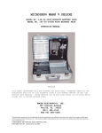
Manual No. 900185
Revision B
March 31, 2000
ANALOG INPUT
SURVEY
INSTRUMENT
POINT (SIPA)
INSTALLATION
AND CHECKOUT
MANUAL FOR
GAS UTILITIES
COPYRIGHT © 1991 by Metretek, Incorporated
All rights to this document, domestic and international, are reserved by Metretek, Incorporated.
No part of this publication may be reproduced, stored in a retrieval system, or transmitted in any
form or by any means (electronic, mechanical, photocopying, recording, or otherwise) without
the prior written permission of Metretek, Incorporated. Requests for permission to reproduce or
distribute this manual should be addressed to:
PUBLICATIONS DEPARTMENT
METRETEK, INCORPORATED
300 NORTH DRIVE
MELBOURNE, FL 32934
The trademark AIS ® is registered (with the) United States Patent and Trademark Office.
2
Table of Contents
CHAPTER ONE: INTRODUCTION TO THE MANUAL .................................................................. 1-1
SCOPE OF MANUAL............................................................................................................................ 1-1
LIST OF ABBREVIATED TERMS ........................................................................................................ 1-2
REFERENCE DOCUMENTS ................................................................................................................ 1-2
Warranty Information ..................................................................................................................... 1-2
FCC Required Notification ............................................................................................................. 1-2
CDOC Equipment Attachment Limitations................................................................................. 1-2
CHAPTER TWO: PRE-INSTALLATION............................................................................................... 2-1
MATERIALS, EQUIPMENT, AND TOOLS ....................................................................................... 2-1
Equipment Supplied by Metretek ................................................................................................. 2-1
Materials Supplied by Metretek..................................................................................................... 2-2
Materials Provided by Customer................................................................................................... 2-2
Tools Required ................................................................................................................................. 2-2
PREPARE FOR FIELD INSTALLATION............................................................................................ 2-3
GATHER SITE INFORMATION.......................................................................................................... 2-3
INSPECT EQUIPMENT......................................................................................................................... 2-3
Unpack and Inspect SIPA ............................................................................................................... 2-3
Verify Telephone Line Installation ................................................................................................ 2-4
Battery Voltage ................................................................................................................................. 2-4
Unpack and Check Lithium Batteries ........................................................................................... 2-4
Unpack and Check Lead-Acid Battery Voltage........................................................................... 2-5
Check Battery Carton Label Dates................................................................................................. 2-5
Storage of Lithium Batteries ........................................................................................................... 2-6
PROGRAM CONFIGURATION PROM ............................................................................................ 2-6
Installed and Programmed PROMs .............................................................................................. 2-6
Uninstalled and Programmed PROMs ......................................................................................... 2-7
i
Table of Contents (Continued)
KYZ BARRIER ........................................................................................................................................ 2-7
VERIFY TELEPHONE LINE................................................................................................................. 3-1
CHAPTER THREE: INSTALLATION OF THE SIPA.......................................................................... 3-1
MOUNT EQUIPMENT.......................................................................................................................... 3-3
INSTALL HUBBLE CONNECTOR...................................................................................................... 3-4
INSTALL CONFIGURATION PROM................................................................................................. 3-5
ATTACH COVER PLATE ..................................................................................................................... 3-8
INSTALL CABLES ................................................................................................................................. 3-8
Attach Input Cables ......................................................................................................................... 3-9
Attach Alarm Cables .................................................................................................................... 3-10
Attach Grounding Cable............................................................................................................... 3-11
VERIFY RING DETECT JUMPER ...................................................................................................... 3-11
CONNECT POWER ............................................................................................................................. 3-12
Install Lithium Batteries................................................................................................................ 3-12
Install AC Power with Lead-Acid Battery.................................................................................. 3-13
Prewired Alarm Cables ................................................................................................................. 3-14
Disconnect Power .......................................................................................................................... 3-14
CALIBRATION OF THE SIPA ........................................................................................................... 3-15
VERIFY OPERATION OF SIPA ......................................................................................................... 3-15
CLOSE THE SIPA................................................................................................................................. 3-16
CHAPTER FOUR: ON-SITE TROUBLESHOOTING ......................................................................... 4-1
FIRMWARE MONITOR MALFUNCTION ........................................................................................ 4-1
TROUBLESHOOTING THE KYZ INPUT CIRCUITRY.................................................................... 4-2
TROUBLESHOOTING THE ALARM CIRCUITRY .......................................................................... 4-2
TROUBLESHOOTING A SIPA THAT WILL NOT CALL IN.......................................................... 4-3
ii
Table of Contents (Continued)
SYNCHRONIZING A METER READING ......................................................................................... 4-4
CHAPTER FIVE: MAINTENANCE ........................................................................................................ 5-1
BATTERY................................................................................................................................................. 5-1
CHAPTER SIX: RETURN EQUIPMENT PROCEDURE ..................................................................... 6-1
RETURN EQUIPMENT PROCEDURE ............................................................................................... 6-1
APPENDIX A: REFERENCE DOCUMENTS........................................................................................ A-1
WARRANTY INFORMATION ........................................................................................................... A-1
FCC-REQUIRED NOTIFICATIONS................................................................................................... A-2
FCC Rules Section 68.104 (Means of Connection)...................................................................... A-2
Standard Data Jacks........................................................................................................................ A-2
FCC Registration Number and Ringer Equivalence Number .................................................. A-2
FCC Rules Section 68.108 (Incidence of Harm)........................................................................... A-2
FCC Rules Section 68.110 (Compatibility of the Telephone Network and Terminal
Equipment) ...................................................................................................................................... A-3
FCC Rules Section 68.216 (Repair of Registered Terminal Equipment and Registered
Protective Circuitry) ....................................................................................................................... A-3
FCC Rules Section 68.218(b) (Instruction to User) ..................................................................... A-3
FCC Rules Section 15.818 (Class A Computing Device: Information to User)...................... A-4
CDOC EQUIPMENT ATTACHMENT LIMITATIONS................................................................ A-5
APPENDIX B: SIPA SPECIFICATIONS ................................................................................................B-1
APPENDIX C: SIPA ALARMS............................................................................................................... C-1
EXTERNAL ALARM INPUTS..............................................................................................................C-1
FIRMWARE GENERATED ALARMS.................................................................................................C-2
APPENDIX D: TELEPHONE CABLE ASSEMBLY ............................................................................. D-1
MATERIAL AND TOOLS REQUIRED .............................................................................................. D-1
CABLE ASSEMBLY INSTRUCTIONS................................................................................................ D-2
APPENDIX E: LIGHTENING PROTECTION WITH A TII STATION PROTECTOR ............... E-1
iii
INDEX ....................................................................................................................................................... I-1
List of Illustrations
Figure 2-1. ECI Layout................................................................................................................................. 2-2
Figure 3-1. ECI Mounting Dimensions ..................................................................................................... 3-3
Figure 3-2. ECI Cover Plate......................................................................................................................... 3-6
Figure 3-3. Diagram of the ECI's Input/Output Board .......................................................................... 3-7
Figure 3-4. ECI Terminal Strip ................................................................................................................... 3-9
Figure 3-5. Telephone Interface Board .................................................................................................... 3-10
Figure 4-1. Mercury Serial Cable Interface Board ................................................................................... 4-3
Figure 5-1. Telephone Interface Board ...................................................................................................... 5-2
Figure E-1. ECI Shield Plate........................................................................................................................ E-2
Figure E-2. ECI Connections to an EC-AT located in a Hazardous Environment.............................. E-3
Figure E-3. Top View of the MTL Barrier ................................................................................................. E-4
List of Tables
Table 3-1. LED Functions .......................................................................................................................... 3-12
Table B-1. ECI Specification Summary....................................................................................................... B-1
Table C-1. ECI Alarm Feature Summary ..................................................................................................C-2
iv
CHAPTER ONE: INTRODUCTION TO THE MANUAL
SCOPE OF MANUAL
This manual explains how to install the Metretek Analog Input Survey Instrument Point
(SIPA). Please take a minute to familiarize yourself with the manual's contents as described
below.
Chapter One: Introduction to the Manual
Following the chapter descriptions given below, you'll find a list of abbreviated terms and
references concerning warranty, FCC and CDOC requirements.
Chapter Two: Pre-Installation
Review this chapter before installing the SIPA in the field. Equipment, materials, and tools
lists are provided. Equipment setup is also explained.
Chapter Three: Installation of the SIPA
Follow the instructions given in this chapter to install the SIPA in the field.
Chapter Four: On-Site Troubleshooting
This chapter explains possible sources of communication or power problems.
Chapter Five: Maintenance
This chapter covers battery life and replacement.
Chapter Six: Return Equipment Procedure
Should you need to return equipment, follow the procedures described in this chapter.
LIST OF ABBREVIATED TERMS
Abbreviated terms used in this manual are spelled out below:
AIS - Advanced Instruction System (Unit Identification Number)
AWG - American Wire Gauge
1-1
MINI-AMP - Metretek Mini-Amplifier Speaker
SIPA - Metretek Analog Input Survey Instrument Point
REFERENCE DOCUMENTS
This section contains information about the SIPA warranty, Federal Communications
Commission (FCC) notification, Canadian Department of Communications (CDOC), and
Canadian Safety Approval (CSA) requirements.
The SIPA module meets or exceeds FCC regulations, CDOC, and CSA requirements as
follows:
•
•
•
•
FCC Rules and Regulations, Part 15, Radio Frequency Devices
FCC Rules and Regulations, Part 68, Connection of Terminal Equipment to the
Telephone Network
Canadian DOC, CS-03, Issue 6, Standard for Terminal Equipment, Systems, Network
Protection Devices, and Connection Arrangements
Canadian Safety Approval
Warranty Information
A warranty is provided for Metretek products. Appendix A details this warranty.
FCC Required Notification
The rules and regulations of the Federal Communications Commission (FCC) specify that
the manufacturer/grantee must notify customers who use FCC-registered equipment of
certain provisions of Part 15 (Radio Frequency Devices) and Part 68 (Connection of Terminal
Equipment to the Telephone Network) of the FCC Rules and Regulations. Appendix A
contains excerpts from these FCC Rules.
CDOC Equipment Attachment Limitations
The Canadian Department of Communications (CDOC) label identifies certified equipment.
This certification means that the equipment meets certain telecommunications network
protective, operational, and safety requirements. Refer to Appendix A for CDOC
limitations.
1-2
CHAPTER TWO: PRE-INSTALLATION
In this chapter, you will verify that you have the proper equipment, materials, and tools to
install the SIPA. Please review this section before going to the field.
MATERIALS, EQUIPMENT, AND TOOLS
Before installing your SIPA, verify that you have the materials, equipment, and tools listed
in this section. Equipment and materials supplied by Metretek are listed first, followed by
materials and tools that you must provide. Figure 2-1 shows an illustration of the SIPA.
Figure 2-1. ECI Layout
Equipment Supplied by Metretek
•
Metretek SIPA
•
One hubble connector
Materials Supplied by Metretek
•
Configuration PROM (Programmed or Unprogrammed)
•
Four lithium battery packs
•
TII station protector
•
Telephone cable (If required, assembly instructions and materials list are provided in
Appendix C.)
Materials Provided by Customer
•
Data input cable, insulated, No. 20 AWG, stranded cable
Alpha 35463 - Metretek Part No. 6145-0100
•
Jumper cable, insulated, No. 20 AWG, single stranded cable
Metretek Part No. ????????????
•
Grounding cable, insulated, No. 12 AWG, solid green
No. 6 terminal lugs
•
A lock or security seal (optional)
2-1
Tools Required
•
A Metretek miniamp (Metretek Part No. 2008-0005B-001)
•
A General National No. 350-2 magnet with 4-lb. pull, or equivalent
•
A No. 6 binder-head screwdriver for terminal block
•
A No. 2 Phillips screwdriver
•
Wire strippers and cutters capable of stripping an 18-20 AWG wire
•
An integrated circuit (IC) extraction tool or a screwdriver with a 1/8-inch blade for use
in removal of the configuration PROM
•
A multimeter
•
Telephone handset with telephone cable (3-5 feet)
•
Lug crimping tool (optional)
•
RJ-11 plug installation tool, AMP Inc., No. 1-231652-0 or Radio Shack No. 64-410
(optional)
PREPARE FOR FIELD INSTALLATION
Before going to the field to install your equipment, perform the following steps:
1. Gather Site Information
2. Inspect Equipment
3. Program Configuration PROM
GATHER SITE INFORMATION
Compile a list of the following information for each SIPA you plan to install:
•
Phone number of the central computer
•
Customer’s address/meter location
•
The Metretek AIS number assigned to the SIPA
•
The SIPA’s enclosure serial number
•
Utility’s account billing number
2-2
INSPECT EQUIPMENT
This section covers the following inspection procedures:
•
•
•
Unpack and inspect SIPA
Verify telephone line installation
Unpack and check batteries voltages
Unpack and Inspect SIPA
Steps below explain how to unpack and inspect the SIPA:
1. Open one end of the carton containing the SIPA and slide it out.
2. Inspect the SIPA for damage.
•
If damage is detected, make a note of the damage and record the affected SIPA’s
serial number. Then, contact Metretek’s Customer Service department at 1-800-3278559.
•
If no damage is detected, continue with the next step.
3. Return the SIPA to its shipping carton to protect it during transportation.
4. Repeat steps 1 through 3 for each SIPA you receive.
Verify Telephone Line Installation
Verify that a telephone line has been installed at each SIPA installation site.
Battery Voltage
Depending on the configuration of the SIPA that you ordered, you will either have lithium
batteries or lead acid batteries. Directions are provided below to unpack and check the
battery voltage for each type of battery.
Unpack and Check Lithium Batteries
Each lithium battery in the storage carton should be checked by the label date as described
below:
1. Remove each lithium battery from the storage carton.
2. Remove the storage resistor from the end of the battery.
3. Check the battery’s open-circuit voltage using a dc voltmeter:
2-3
•
3.6 volts dc or greater
No further action is required. The battery is capable of supplying the SIPA with the
required voltage.
•
3.59 volts dc or less
Dispose of the lithium battery properly. If your unit is under warranty, contact
Metretek's Customer Service Department for replacement batteries.
CAUTION
Do not recharge the lithium batteries.
4. Return the usable lithium batteries to their storage carton.
Unpack and Check Lead-Acid Battery Voltage
Each lead-acid battery in the storage carton should be checked by the label date as described
below:
1. Remove each lead-acid battery from the storage carton.
2. Check the battery’s open-circuit voltage using a dc voltmeter:
•
4.2 volts dc or greater
No further action is required. The battery is capable of supplying the SIPA with the
required voltage.
•
4.19 volts dc or less
Recharge the battery with a battery charger. Do not overcharge the battery.
3. Return the usable lead-acid batteries to their storage carton.
Check Battery Carton Label Dates
When batteries are shipped separately, a label is placed on the top of each battery carton
defining the following:
•
The date that the batteries in the box were last checked at Metretek.
•
The date that you should check each stored battery's open-circuit voltage.
2-4
Figure 2-2 is an example of the battery label.
THE ENCLOSED BATTERIES WERE CHECKED
ON 09/30/91
CHECK OCV ON 01/30/92
RECOMMENDED STORAGE TEMPERATURE 20oC
OR LESS
(Check Guidelines Enclosed)
Figure 2-2. Typical Battery Carton Label
Storage of Lithium Batteries
If the batteries are to be stored for more than two months before installation, the batteries in
the units
should be placed in an area with an ambient temperature of approximately 68 degrees F (20
degrees C) maximum.
Lithium batteries build up a passivation layer during storage that limits the battery's output
voltage under pulse loads (such as placing a call) until this layer is burned off by use. The
36K-ohm resistor that was shipped attached to the battery pack provides sufficient current
drain to the battery to prevent passivation layer formation. The resistor is a .25 watt
resistor. This 36K-ohm resistor must be removed when the battery is attached to a SIPA and
placed in service. Once the battery is in service, the passivation layer will not form due to
the constant current drain.
If a battery is taken out of service, the resistor should be replaced for storage. This storage
method consumes a very small percentage of the battery's expected life for each year of
storage. However, it permits the battery to be installed without any pretreatment. A
battery stored for two years under these circumstances will still maintain 90% of its original
capacity.
If a battery pack has been in storage for a long period of time without a 36K-ohm resistor
attached, a passivation layer could have formed. To ensure proper operation of the battery,
this layer must be burned off. Follow the steps below to burn off the passivation layer:
•
Measure the voltage of the battery with a 51-ohm resistor placed across its terminals.
•
If the voltage is less than 3.3 volts dc, leave the 51-ohm resistor across the battery
terminals for 30 minutes. This will burn off the passivation layer so that the battery
will function properly.
•
If after 30 minutes the battery voltage is less than 3.3 volts dc, the battery is defective
and should not be used in an SIPA.
2-5
PROGRAM CONFIGURATION PROM
The SIPA configuration PROM may be shipped to you in one of three ways:
•
•
•
Installed and Programmed
Uninstalled and Programmed
Uninstalled and Unprogrammed
Installed and Programmed PROMs
If the configuration PROM is programmed and installed in the SIPA, the SIPA can be
installed in the field. A programmed PROM will have a label on it with the AIS number.
Uninstalled and Programmed PROMs
A programmed PROM will have a label on it with the AIS number. Since the configuration
PROM is not installed, installation directions will be provided later in this manual.
Uninstalled and Unprogrammed PROMs
If the configuration PROM is not programmed, there are two ways to program your PROM:
•
If you have purchased a Metretek Programmer, please refer to manual no. 900203
(Metretek Programmer Hardware and Software User manual).
•
If you have purchased a Curtis Nammer Programmer, please refer to manual no.
600017 (Programming a SIP Configuration PROM Using a Curtis PR5200B Universal
Nammer).
KYZ BARRIER
The SIPA is not classified as being intrinsically safe. If the SIPA is to monitor analog output
in a hazardous area, follow you company's policy for hazardous location installations.
Metretek offers a KYZ Barrier that can be used for hazardous location installations. Refer to
Metretek Manual No. 900104 (Multichannel KYZ Barrier Installation manual) before
installing the SIPA in the field.
2-6
CHAPTER THREE: INSTALLATION OF THE SIPA
This section explains how to install the SIPA in the field. (Before continuing, make sure
you've completed the pre-installation steps in Chapter Two.) Refer to Appendix B for the
SIPA specifications and Appendix C for Alarm Configurations.
VERIFY TELEPHONE LINE
Before installing the SIPA, you should verify that the telephone line is functional by
following the steps listed below:
1. Install the RJ-11C telephone receptacle outside any hazardous location if it has not
been installed.
2. Mount the TII Telephone Station Protector in a suitable location. Wiring of the
station protector is shown below:
3. Connect one end of the 12 AWG earth ground wire to the center terminal on the TII
protector. Appendix F provides a data sheet detailing the TII Telephone Station
Protector.
4. Connect the other end of the earth ground wire to a solid earth ground in
conformance with national and local electrical code regulations.
5. Route the telephone cables from the telephone company connector and the SIPA
through the bottom of the TII station protector.
6. Connect the red wires from both of the telephone cables to the left screw inside the
TII station protector.
7. Connect the green wires from both of the telephone cables to the right screw inside
the TII station protector.
3-1
8. Plug a telephone into the RJ-11C receptacle.
9. Check for a dial tone. (This procedure will test the telephone cable and the
telephone line.)
•
If no dial tone is detected, a problem exists with the telephone line which must
be repaired before continuing the SIPA installation process.
•
If a dial tone is detected, continue with the next step.
10. Dial the telephone number assigned to the Metretek central computer.
11. Listen to the telephone receiver to verify that the computer answers the call and
responds with a tone burst.
12. Hang up the telephone test set.
MOUNT EQUIPMENT
Attach the SIPA to a wall or pipe near the meter. Refer to Figure 3-1 which shows the
measurement youwill need to mount the SIPA.
Figure 3-1. SIPA Mounting Dimensions
INSTALL HUBBLE CONNECTOR
The hubble connector is usually shipped connected to the SIPA upside down. Listed below
are the directions to install the hubble connectors:
1. Open the door of the enclosure.
2. Remove and disassemble the hubble connectors from the inside of the bottom of the
SIPA.
3. Insert the smaller end of the threaded coupler through the hole in the bottom of the
SIPA.
4. Screw the lock nut on the small end of the threaded coupler with the ridges on the lock
nut pointed down. Turn the lock nut until the threaded coupler is held securely in
place.
5. Save the other three parts of the hubble connector. They will be installed later.
3-2
INSTALL CONFIGURATION PROM
Steps for installing the configuration PROM in the SIPA board are given below.
1. Unplug the telephone cable from the SIPA telephone interface board.
2. Remove the telephone interface board by removing the three screws shown in Figure 32. Retain these screws for later use.
3. Remove the shield plate to gain access to the SIPA board by removing the four screws
shown in Figure 3-2. Retain these screws for later use.
Figure 3-2. SIPA Cover Plate
4. Locate U16 in the upper left-hand corner on the SIPA board. Refer to Figure 3-3 to
determine the location.
CAUTION
Do not touch the other components on the PC board.
5. Install the configuration PROM in the IC socket at location U16, such that the PROM's
notch aligns with the outline on the PC board.
6. Press the PROM down until it's firmly seated in the IC socket.
Figure 3-3. Diagram of the SIPA's Input/Output Board
ATTACH COVER PLATE
1. Attach the SIPA shield plate.
2. Screw the four phillips screws into the corners of the SIPA shield plate.
3. Press the telephone interface board gently into place. Make sure that the rectangular
connector contacts the SIPA board securely.
4. Screw the three phillips screws into the telephone interface board.
5. Insert the telephone cable through the extra hubble connector parts in the following
order: the end cap, the compression fitting, and the rubber grommet.
6. Route the telephone cable through the threaded coupler attached to the SIPA.
7. Plug the telephone cable into the SIPA's telephone interface board.
3-3
INSTALL CABLES
The cables needed are listed below:
•
•
•
•
KYZ input cables
Alarm cables
Analog input cables
Grounding cable
1. Insert the cables through the extra hubble connector parts in the following order: the end
cap, the compression fitting, and the rubber grommet.
2. Feed the cables through the threaded coupler attached to the SIPA.
3. Attach No. 6 terminal lugs to the ends of each of the input cables and the alarm cables
(optional). Do not attach a terminal lug to the grounding cable
Attach Input Cables
The input cables can be attached to the terminal strip in either of four ways: a Form C, a
Form A, Voltage Mode, or current Mode. Figure 7-3 shows the terminal strip.
Figure 3-4. SIPA Terminal Strip
•
Form C (KYZ 3-wire)
Attach the KYZ input to K1, Y1, and Z1 on the terminal strip. K1 is always ground
or common.
•
Form A (2-wire)
Attach the input to K1 and Y1 on the terminal strip. K1 is always ground or
common.
•
Voltage Mode
Attach the first transducer power input to SW PWR1.
Attach the transducer ground or common to RTN1.
Attach the transducer output to ANA1.
You can have two additional inputs; attach the inputs as listed above to the second
and third channels.
3-4
•
Current Mode
Attach the first transducer (+) connection to ANA1.
Attach the transducer (-) connection to RTN1.
You can have two additional inputs; attach the inputs as listed above to the second
and third channels.
Attach Alarm Cables
There are three alarm hookups on the terminal strip: Alarm 1, Alarm 2, and Tamper.
•
Alarm 1
Alarm 1 is a normally open alarm input and can be wired for a customer-specified
alarm. The ground wire must be connected to Alarm C on the terminal strip.
•
Alarm 2
Alarm 2 is a normally open alarm input and can be wired for a customer-specified
alarm. The ground wire must be connected to Alarm C on the terminal strip.
•
Tamper
Tamp+ is a normally closed alarm input and is usually prewired from the factory as
a tamper alarm and is connected to the magnetic switch found on the enclosure side
wall.
Attach Grounding Cable
To attach the grounding cable, follow the steps below:
1. Loosen the grounding screw. Refer to Figure 3-2 to determine the location of the
grounding screws.
2. Form the 12 AWG grounding cable to fit around the grounding screw as shown below.
3. Attach the 12 AWG grounding cable to the grounding screw.
4. Tighten the screw to secure the wire.
5. Connect the opposite end of the grounding lead to a true earth ground having a
resistance of less than one ohm with respect to earth.
3-5
VERIFY RING DETECT JUMPER
The Ring Detect option allows the SIPA to answer incoming calls from the Metretek
computer system. If you ordered ring detect capabilities on your SIPA, verify that jumper
JP1 is installed on the telephone interface board which is shown in Figure 3-5.
•
•
To enable ring detect, place a jumper over JP1 on the telephone interface board.
To disable ring detect, remove the jumper JP1 from the telephone interface board.
Figure 3-5. Telephone Interface Board
Two alternative sources of power for this unit are four lithium batteries or ac power with a
lead-acid backup battery. This section explains where to attach the batteries to the SIPA
board.
Install Lithium Batteries
To install the lithium batteries in the SIPA, follow the steps below.
1. Install the four lithium battery packs into the compartment on the SIPA's enclosure door.
The batteries should be installed vertically with the wires at the top as illustrated in
Figure 2-1. Tighten the screws on the cover to hold the batteries in place.
2. Remove the load resistor from the battery pack. (If a resistor is not on the battery pack, a
passivation layer could exist and will affect initial battery output voltage. Refer to
Chapter Two, Storage of Batteries, which discusses how to burn off a passivation layer.)
3. Connect the wire from the each lithium battery pack to battery connectors, J2, J3, J9, and
J10, on the SIPA board. The SIPA board shown in Figure 3-3 shows the location of the
battery connectors.
4. Once the SIPA is powered up, the SIPA's GREEN FIRMWARE MONITOR indicator
should light solid, indicating that RAM and diagnostic tests are running. If the tests are
completed successfully, the FIRMWARE MONITOR indicator will blink at a 1 Hz rate.
The unit will then attempt to call the central computer. Table 3-1 describes the SIPA's
LED indicators.
3-6
LED
FUNCTION
ANA 3
Lights to indicate analog channel 3 status
ANA 2
Lights to indicate analog channel 2 status
ANA 1
Lights to indicate analog channel 1 status
Z
When the K-to-Z contact closure occurs, the indicator lights.
Y
When the K-to-Y contact closure occurs, the Y indicator lights.
GOOD CALL
If the previous call is successful, the GOOD CALL indicator lights. When a ca
in process, the indicator turns off. If the call is successfully completed, the
indicator lights again.
FIRMWARE MONITOR If the system is operating properly, the FIRMWARE MONITOR blinks at 1 Hz
TABLE 3-1. LED FUNCTIONS
The status LEDs function when the SIPA's LED switch is activated by a magnet or when the
SIPA detects a TAMPER alarm (enclosure door open). The LED magnetic switch (located in
the lower right corner of the SIPA) lights the LEDs for one minute for each second that the
switch is held closed by a magnet (up to a maximum of four minutes). The unit lights the
LEDs for four minutes when it detects a TAMPER alarm.
Install AC Power with Lead-Acid Battery
To install the lithium batteries in the SIPA, follow the steps below.
1. Connect the AC power cable to the 120 to 24 volt step down transformer. On the first
sample transformer in Figure 3-6, connect AC power to L1 and L2. On the second
sample transformer, connect AC power to AC and AC.
CAUTION
The 120 to 24 volt step down transformer is for indoor use only.
To prevent fire or electrical shock, connect directly to a grounding
receptacle (3-prong).
Figure 3-6. 120 to 24 Volt Step Down Transformer
2. Run the AC power cable through the hubble connector.
3. Connect the AC power cable to the terminal strip on the power board. The terminal
strip is shown in Figure 3-7.
Figure 3-7. AC Power Board
4.
Remove the screws holding the battery shield plate as shown in Figure 3-8.
3-7
5. Mount the lead acid battery with its terminals on top. The lead acid battery is 4 volts, at
10 amp hours. Verify that the battery is 4.2 volts or greater before installing. If the
battery is under 4.2 volts and under warranty, contact customer service to order a
replacement.
6. Connect the wires from J1 on the AC power board to the battery. Refer to Figure 3-6 for
the exact location of J1.
•
Connect the red wire to the positive terminal.
•
Connect the black wire to the negative terminal.
•
Verify that the power supply plug from the AC power board is connected to J2 or J3
on the Analog SIP board. Figure 3-8 shows the location of the battery connectors J2
and J3.
Figure 3-8. AC-Powered Analog SIP
Prewired Alarm Cables
Alarm 1, Alarm 2, and Alarm C have been prewired by Metretek. These wires run from the
AC power board to the terminal strip on the Analog SIP board. Verify that the wires are
connected properly.
•
•
•
Red wire - Alm 1 (AC off)
White wire - Alm 2 (AC on)
Black wire - Alm C (Common)
Disconnect Power
If you need to disconnect the power for any reason, unplug the battery plug from J3 or J2 on
the Analog SIP board.
CALIBRATION OF THE SIPA
The SIPA can be used to calibrate the data transmitter attached to each of the three SIPA
inputs. This is possible if the data transmitter can be stimulated with the full range of the
input. For examples:
•
0 psi and 100 psi for a 0 to 100 psi pressure data transmitter.
•
Resistor could be connected to the input of a RTD transmitter to give 0 and 100%
readings.
When the analog test switch is closed one of the three analog channels will be sampled
approximately twice a second. The corresponding analog channel LED will light when the
input is within range.
3-8
Therefore, the zero and full scale for the data transmitter can be adjusted by:
•
Connect the minimum input
•
Adjust the zero adjustment until the LED just goes off
•
Connect the maximum input to the data transmitter
•
Adjust the span adjustment unit the LED just goes off
After one channel's data transmitter is calibrated, the next one may be calibrated by either
activating the ANALOG TEST switches or activating the magnetic CALL SWITCH.
VERIFY OPERATION OF SIPA
To verify that the SIPA is operating, a communication call must be initiated.
1. Verify that the phone cable is hooked into the SIPA telephone interface board.
2. Activate the magnetic switch labeled "CALL" located on the outside of the enclosure. A
magnet is required to activate this switch. Figure 3-3 shows the location of the magnetic
switch on the SIPA board.
3. Listen to the call with the telephone test set (optional).
4. Verify that the GOOD CALL indicator located on the SIPA board illuminates in
approximately 15 to 30 seconds. This will show that the call just made was successfully
received by the computer.
If the GOOD CALL indicator does not light, refer to Chapter 4, Onsite Troubleshooting.
If the GOOD CALL indicator does light, read the meter dials and write down these
values as sell as the time the meter read was taken.
5. Verify that the KYZ data input is functioning properly by observing the following while
data is being collected:
•
For KYZ data inputs, the Y and Z indicators light alternately as the contact
closure transfers from the Y to the Z contact; or for Form A data inputs, verify the
Y indicator flashes during data collection.
•
When ANALOG channel 1, 2, or 3 are active, the ANA 1 LED, ANA 2 LED, and
ANA 3 LED will blink at the following rate:
0 - 25% of full scale
26 - 50% of full scale
51 - 75% of full scale
76 - 100% of full scale
once every 4 seconds
once per second
four times per second
sixteen times per second
3-9
If any of the indicator lights fail to light, refer to Chapter 4, Onsite Troubleshooting.
6. If using KYZ input to record meter reading, place a telephone call to the office and
report the meter-reading values to the computer operator. The computer operator must
enter these values in the current index readings in the AIS Information
Display/Maintenance program. Note, these values can be hand carried back to the
office.
CLOSE THE SIPA
To close the SIPA, perform the following steps:
1. Attach the extra hubble parts: the rubber grommet, the compression fitting, and the end
cap.
2. Close and latch the door of the SIPA.
3. Padlock the SIPA and attach a security seal (optional).
3-10
CHAPTER FOUR: ON-SITE TROUBLESHOOTING
If your SIPA does not operate properly, please review the troubleshooting procedures given
below. If you are still unable to correct the problem, contact Metretek’s Customer Service
Department.
FIRMWARE MONITOR MALFUNCTION
If the FIRMWARE MONITOR light fails to light or begin to blink at the 1-Hz rate after the
self-test, check the following:
•
Verify that the SIPA lithium battery has an open circuit voltage of 3.6 vdc or greater
with a DVM.
NOTE
If the battery voltage is low, replace it.
•
Disconnect the batteries from the unit from J2, J3, J9, or J10.
•
Remove the SIPA's telephone interface board and shield plate.
•
Verify that all socketed parts on the printed circuit board are seated and oriented
properly.
•
Replace the unit's shield plate and telephone interface board.
•
Record the problem on the checklist in Chapter Six and return it with the unit to
Metretek for repair if any of the above steps failed.
TROUBLESHOOTING THE KYZ INPUT CIRCUITRY
If a problem with the KYZ circuitry is suspected, follow the steps listed below:
•
Remove input power and detach all input wires form the SIPA's terminal block
(TB1).
•
Apply power to the SIPA and wait until the GREEN FIRMWARE MONITOR LED
inside the SIPA begins to blink.
NOTE
During this test, you may need to activate the unit's LED MAGNETIC
SWITCH to re-enable the SIPA's status indicator LEDs.
4-1
•
Check the KYZ input as follows:
1. Connect Terminal K to Y and verify that the Y indicator turns ON.
2. Connect Terminal K to Z and verify that the Z indicator turns ON.
•
Voltage Mode SIPA - Connect a 240K ohm resistor between SW PWR 1 and ANA 1.
The ANA 1 LED should change from switching on and off every four seconds to four
times a second.
Current Mode SIPA - Connect a 1800 ohm resistor between ANA1 and RTN 1. The
ANA 1 LED should change from switching on and off every four seconds to four
times a second.
Repeat this step for inputs 2 and 3 as needed.
•
Record the problem on the checklist in Chapter Six and return it with the unit to
Metretek for repair if any of the above steps failed.
TROUBLESHOOTING THE ALARM CIRCUITRY
If a problem with the alarm circuitry is suspected, perform the following:
•
Attach a functional telephone line to the SIPA and apply power to the SIPA. Wait
for the SIPA to complete its self-test and place a call to the central computer.
•
Test the TAMPER alarm input by connecting the TPR + terminal to the TPR terminal for 2 seconds. The SIPA should go off-hook and report a TAMPER
DETECT alarm.
•
Test the CUSTOMER ALARM inputs as follows:
1. Connect the ALM C terminal to the ALM 1 terminal for 2 seconds. The unit
should go off-hook and report a CUSTOMER ALARM 1.
2. Connect the ALM C terminal to the ALM 2 terminal for 2 seconds. The unit
should go off-hook and report a CUSTOMER ALARM 2.
•
TEST the MAGNETIC SWITCH alarm input by placing a magnet close to the CALL
label on the upper right corner of the SIPA for 2 seconds. The unit should go offhook and report a MAGNETIC SWITCH alarm.
NOTE
If the SIPA is in retry mode because an alarm has been sensed, the only
way to override the alarm's retry call is to use a magnet and the SIPA's
internal magnetic switch to force the SIPA to place another call.
4-2
•
Record the problem on the checklist in Chapter Six and return it with the unit to
Metretek for repair if any of the above steps failed.
TROUBLESHOOTING A SIPA THAT WILL NOT CALL IN
NOTE
If the SIPA is in retry mode because of an overdue call situation or an
alarm has been sensed, the only way to override the alarm's retry call is to
use a magnet and the SIPA's internal magnetic switch to force the SIPA to
place a call.
•
Verify that the phone line is functional by disconnecting the phone line from the
SIPA and plugging it into one side of the miniamp and check for a dial tone. (This
procedure allows the testing of the telephone cable as well as the telephone line
itself.)
•
A DVM should also be used to check for a functional telephone line. A good line
will have an on-hook voltage of approximately 50 volts dc across the TIP and RING
lines (RED and GREEN wires, respectively), and an off-hook voltage of less than 15
volts dc.
•
Use an ohmmeter to verify that Fuses F1 and F2 are not open. The fuses are located
beneath the telephone interface shield plate where the phone wires terminate on the
PC board.
NOTE
No more than 30 seconds can elapse between the time that the SIPA dials
the last digit in a phone number and the time that it connects with the
central computer's SMOD; otherwise, the SIPA will time out and hang up
before the call is completed.
SYNCHRONIZING A METER READING
To synchronize the data being reported with the actual meter reading displayed at the
customer's meter, a person at the customer installation site should perform the following:
•
Initiate a call (either use a magnet to activate the SIPA's MAGNETIC CALL SWITCH
alarm or open the unit's door to activate its TAMPER alarm).
•
Read the index of the meter or corrector being monitored as the unit is making the
call and write down the index value and the time the reading is taken.
4-3
•
Verify the call was good by checking the GOOD CALL LED (the LED MAGNETIC
SWITCH will have to be activated).
•
Call the computer operator to report the meter reading observed if the call was good.
4-4
CHAPTER FIVE: MAINTENANCE
Your Metretek SIPA requires little maintenance. To ensure proper operation of the SIPA,
follow the guidelines for battery replacement given below.
BATTERY
The SIPA operates on a four lithium battery packs. Lithium batteries should be replaced
when a low battery alarm occurs. The table below shows approximate battery life and the
approximate life remaining after a low battery alarm is received.
Battery Type
Battery Life
*Battery Replacement
4 Lithium Batteries
Approx. 1 years
Approx. 3 months
*Battery Replacement—the battery life remaining after a low battery alarm is received.
5-1
NOTES
5-2
CHAPTER SIX: RETURN EQUIPMENT PROCEDURE
If you should encounter a problem with the sipa, refer to Chapter Five: On-Site
Troubleshooting. If the problem can't be remedied, return the SIPA to Metretek using the
return equipment procedure given below.
RETURN EQUIPMENT PROCEDURE
To return equipment to Metretek, please follow the procedure below:
1. Contact Metretek's Customer Service Department at 1-800-327-8559 and obtain a Return
Authorization (RA) number.
2. Complete the checklist on the next page.
3. Return the completed checklist and equipment to Metretek using your company's
standard procedures.
6-1
SIPA FAILURE CHECKLIST
Customer:
AIS No.:
RA No.:
Serial No.:
Date SIPA Removed:
Reported By:
Location:
Last Call Date and Time:
Please circle the number (and/or letter) at which the unit failed:
1. Communications
a. Initiation of alarm call, scheduled call, or after passing a magnet over the unit's
magnetic switch
b. SIPA goes off-hook; dial tone - 5 seconds
c. SIPA dials central computer's telephone number
d. SIPA's call rings central computer
e. Computer answers with a carrier signal
f. SIPA immediately transmits status data block to central computer
g. Pause while central computer is processing SIPA's status data block
h. Central transmits command message to SIPA
i. If central requests SIPA's data, SIPA immediately transmits data block(s) to central
j. Central hangs up
*k. SIPA hangs up
*NOTES • If call from SIPA was successful, the GOOD CALL indicator will light
• If call was not successful, the GOOD CALLl indicator will not light and
the SIPA will be in its retry mode
• If communication fails, either the SIPA or the modem will transmit 3 or 4
inquiry tones that are spaced apart in an effort to reestablish
communication
2. Unit calls excessively. State the alarms that caused unit to have excessive calls:
3. Input failure descriptions:
KYZ Input
ANA 1
ANA 2
ANA 3
4. FIRMWARE MONITOR not blinking or LEDs are in an abnormal state.
5. Other (please be specific):
Visual Inspection:
Please enclose this checklist with the ECI being returned to:
Metretek, Incorporated
300 North Drive
Melbourne, FL 32934
6-2
APPENDIX A: REFERENCE DOCUMENTS
WARRANTY INFORMATION
The seller warrants its hardware to be free from defects in material and workmanship under
normal and proper use for a period of 12 months from the date the hardware is shipped
from Metretek, Incorporated. The seller’s sole liability and the buyer’s sole remedy for any
breach of the foregoing provision is, at the seller’s option, the timely no-charge repair or
replacement of any defective hardware or part that Metretek inspects and finds reasonable
evidence that a defect in material or workmanship exists. The buyer shall provide the labor
required to remove the defective hardware and install its replacement at no charge to the
seller. The equipment will be shipped to the seller at the buyer's expense. The replacement
or repaired equipment will be shipped to the buyer at the seller's expense.
Warranty claims to be honored under this warranty must be made promptly. Such claims
shall specify the nature and details of the claim, the date that the cause of the claim was first
observed, and the affected equipment’s unit serial number. Defective equipment shall not
be returned to the seller’s factory without prior authorization from the seller. A copy of the
claim’s documentation must be attached to the defective equipment and sent to the seller’s
manufacturing facility. Defective components replaced under this warranty shall become
the property of the seller.
The seller makes no representation or warranty other than those set forth in this agreement.
THE WARRANTY STATED HEREIN IS EXPRESSLY IN LIEU OF ALL WARRANTIES,
EXPRESSED OR IMPLIED, INCLUDING BUT NOT LIMITED TO, ANY EXPRESSED OR
IMPLIED WARRANTY OF MERCHANTABILITY OR FITNESS FOR A PARTICULAR
PURPOSE. SUCH WARRANTY CONSTITUTES THE ONLY WARRANTY MADE BY THE
SELLER WITH RESPECT TO THIS AGREEMENT, THE EQUIPMENT UNITS, OR THE
SERVICES TO BE SUPPLIED HEREBY. THE SELLER SHALL NOT BE LIABLE FOR ANY
INCIDENTAL OR CONSEQUENTIAL DAMAGES OF ANY KIND.
This warranty will not extend to equipment subjected to accident, to misuse, or to
alterations/repair not made and documented in writing by Metretek.
A-1
FCC-REQUIRED NOTIFICATIONS
The Federal Communication Commission (FCC) requires that the following statements be
listed for this equipment.
FCC Rules Section 68.104 (Means of Connection)
The following paragraph is excerpted from Section 68.104(a):
Except for telephone company-provided ringers and except as provided in Paragraph
(c), all connections to the telephone network shall be made through the standard Plugs
and standard telephone company-provided jacks, or equivalent, described in Subpart F,
in such a manner as to allow for easy and immediate disconnection of the terminal
equipment. Standard jacks shall be so arranged that, if the plug connected thereto is
withdrawn, no interference to the operation of equipment at the customer's premises
which remains connected to the telephone network, shall occur by reason of such
withdrawal.
Standard Data Jacks
The standard data jacks with which the FCC-registered model(s) of the equipment covered
in this technical manual will connect are listed and briefly described in this manual.
FCC Registration Number and Ringer Equivalence Number
The FCC registration number and ringer equivalence number are contained on the label on
the registered equipment.
FCC Rules Section 68.108 (Incidence of Harm)
The following paragraph has been excerpted from Section 68.108:
Should terminal equipment or protective circuitry cause harm to the telephone network,
the telephone company shall, where practicable, notify the customer that temporary
discontinuance of service may be required; however, where prior notice is not
practicable, the telephone company many temporarily discontinue service forthwith, if
such action is reasonable in the circumstances. In case of such temporary
discontinuance, the telephone company shall (1) promptly notify the customer of such
temporary discontinuance, (2) afford the customer the opportunity to correct the
situation which gave rise to the temporary discontinuance, and (3) inform the customer
of the right to bring a complaint to the Commission pursuant to the procedures set forth
in Subpart E of this Part.
A-2
FCC Rules Section 68.110 (Compatibility of the Telephone Network and Terminal Equipment)
The following paragraph has been excerpted from Section 68.110 (b):
Changes in Telephone Company Facilities, Equipment, Operations or Procedures.
The telephone company may make changes in its communications facilities, equipment,
operations, or procedures, where such action is reasonably required in the operation of
its business and is not inconsistent with the rules and regulations in this Part. If such
changes can be reasonably expected to render any customer's terminal equipment
incompatible with telephone company communications facilities, or require
modifications or alterations of such terminal equipment, or otherwise materially affect is
use or performance, the customer shall be given adequate notice in writing, to allow the
customer an opportunity to maintain uninterrupted service.
FCC Rules Section 68.216 (Repair of Registered Terminal Equipment and Registered Protective
Circuitry)
The following paragraph has been excerpted from Section 68.216:
Repair of registered terminal equipment and registered protective circuitry shall be
accomplished only by the manufacturer or assembler thereof or by their authorized
agent; however, routine repairs may be performed by a user, in accordance with the
instruction manual if the applicant certifies that such routine repairs will not result in
noncompliance with the rules and regulations in Subpart D of this Part.
FCC Rules Section 68.218(b) (Instruction to User)
The following paragraphs have been excerpted from Section 68.218(b):
(2) . . . registered terminal equipment or protective circuitry may not be used with party
lines or coin lines.
(3) . . . when trouble is experienced the customer shall disconnect the registered
equipment from the telephone line to determine if the registered equipment is
malfunctioning and the use of such equipment shall be discontinued until the
problem has been corrected.
A-3
FCC Rules Section 15.818 (Class A Computing Device: Information to User)
The FCC requires that the user of all Class A equipment be provided with the following
notice as defined in Section 15.818:
WARNING
This equipment generates, uses, and can radiate radio frequency energy
and if not installed and used in accordance with the instructions manual,
may cause interference to radio communications. It has been tested and
found to comply with the limits for a Class A computing device pursuant
to Subpart J of Part 15 of FCC Rules, which are designed to provide
reasonable protection against such interference when operated in a
commercial environment. Operation of this equipment in a residential
area is likely to cause interference in which case the user at his own
expense will be required to take whatever measures may be required to
correct the interference.
If this equipment does cause interference to radio or television reception, which can be
determined by turning the equipment off and on, the user is encouraged to try to correct
the interference by one or more of the following measures:
•
Reorient the receiving antenna
•
Relocate the computer with respect to the receiver
•
Move the computer away from the receiver
•
Plug the computer into a different outlet so that computer and receiver are on
different branch circuits
•
If necessary, the user should consult the dealer or an experienced
radio/television technician for additional suggestions.
Instructions on the operation, installation, maintenance, and testing of the registered
equipment are contained in sections of this manual.
A-4
CDOC EQUIPMENT ATTACHMENT LIMITATIONS
NOTICE
The Canadian Department of Communications (CDOC) label identifies certified equipment.
This certification means that the equipment meets certain telecommunications network
protective, operational and safety requirements. The Department does not guarantee the
equipment will operate to the user’s satisfaction.
Before installing this equipment, users should ensure that it is permissible to be connected
to the facilities of the local telecommunications company. The equipment must also be installed using an acceptable method of connection. In some cases, the company’s inside
wiring associated with a single line individual service may be extended by means of a
certified connector assembly (telephone extension cord). The customer should be aware
that compliance with the above conditions may not prevent degradation of service in some
situations.
Repairs to certified equipment should be made by an authorized Canadian maintenance
facility designated by the supplier. Any repairs or alterations made by the user to this
equipment, or equipment malfunctions, may give the telecommunications company cause
to request the user to disconnect the equipment.
Users should ensure for their own protection that the electrical ground connections of the
power utility, telephone lines and internal metallic water pipe system, if present, are
connected together. This precaution may be particularly important in rural areas.
CAUTION
Users should not attempt to make such connections themselves, but
should contact the appropriate electric inspection authority, or electrician,
as appropriate.
NOTE
The Load Number (LN) assigned to each terminal device denotes the
percentage of the total load to be connected to a telephone loop which is
used by the device, to prevent overloading. The termination on a loop
may consist of any combination of devices subject only to the requirement that the total of the Load Numbers of all the devices does not
exceed 100. An alphabetic suffix is also specified in the Load Number for
the appropriate ringing type (A or B), if applicable. For example, LN = 20
A designates a Load Number of 20 and an “A” type ringer.
ATTENTION
The SIPA module does not exceed the Class A limits for radio noise emissions from digital
apparatus set out in the Radio Interference Regulation of the CDOC.
A-5
NOTES
A-6
APPENDIX B: SIPA SPECIFICATIONS
The SIPA is packaged in a National Electrical Manufacturer's Association (NEMA) oil-tight,
dust-free, fiberglass enclosure. The NEMA 4 enclosure has a quick-release JIC clamp. SIPA
specifications are summarized below in Table B-1.
Table B-1. SIPA Specification Summary
Parameter
Specification
Power:
Lithium Battery (4 required):
Voltage
3.6 volts dc
Capacity
30 ampere-hours (nominal)
Termination
4-position locking connector
Storage Temperature
for optimum battery life
68 degrees F (20 degrees C)
Lead-Acid Battery:
Voltage
4.0 volts dc
Capacity
30 ampere-hour (nominal)
Termination
4-position spade terminal connector
Storage temperature
for optimum battery life
68 degrees F (20 degrees C)
AC Power:
24 VAC - 10 VA required
B-1
Table B-1. SIPA Specification Summary (Continued)
Parameter
Specification
Operating Environment:
Temperature Range
Lithium battery
-22 to +150 degrees F
(-30 to +65 degrees C)
Lead-Acid battery
-22 to +130 degrees F
(-30 to +65 degrees C)
Relative humidity range
10 to 98 percent noncondensing
Maximum rate of temperature change
2 degrees F/minute
(1.1 degrees C/minute)
Enclosure:
Height
11.31 inches (28.73 cm)
Width
8.75 inches (22.23 cm)
Depth
5.50 inches (14.00 cm)
Weight
12.00 pounds (5.40 kg)
Telephone interface requirements:
FCC Registration No.
BK585U-10435-MD-E
Ringer equivalence
0.2 B
CDOC Certification No.
764 2945 A
Load Number
22
Dialing (i.e., addressing):
Pulse dialing mode:
Dial rate
10 pulses/second
Percent break
63 percent (nominal)
Interdigit interval
800 ms
Dialing digits
31 (maximum)
Pause mode
Programmable
B-2
Table B-1. SIPA Specification Summary (Continued)
Parameter
Specification
DTMF mode:
Deviation from standard tone
.73 percent (maximum)
Dial rate
3.3 digits/second
Interdigit interval
150 ms
Dialing digits
31 (maximum)
Pause mode
Programmable
Communication signals:
Output level
Less than -9 dBm (fixed)
Modem sensitivity
-40 dBm (minimum)
Telephone connector
4-conductor, modular
telephone assembly
with USOC RJ-11C terminations
Customer inputs:
Customer counting input arrangements
KYZ (Form C) or Form a mercury
wet with a maximum line resistance
of 200 ohms and with snap action;
electrically dry
Number:
Form C
1
Form A
1
Input rate:
Form C (KYZ)
1200 counts/minute (max)
Form A
600 counts/minute (max)
Time closed
40 msec dwell time (min)
Maximum contact resistance
Line resistance plus contact
resistance must be <200 Ohms
Contact bounce
10 msec (max)
B-3
Table B-1. SIPA Specification Summary (Continued)
Parameter
Specification
Customer analog input arrangements
Either 1-5 volt or 4-20 mA loop
hardware configuration
Number:
1, 2, or 3 available via hardware
configuration
Inputs:
4 - 20 mA current loop is wet by
2 - 30 volt supply during sample
interval 1 - 5 volt inputs are
100K ohm load
Accuracy
.25%
Bit resolution
10 bits 1 part in 1024 (0.1%)
-20
C-
50
C
Standard hardware alarms:
Contact input arrangement:
TAMPER alarm
Form B (normally closed, transition
to open causes an alarm)
ALARMS 1 and 2
Form A (normally open, transition to
closed causes an alarm)
Maximum contact resistance
Line resistance plus contact
resistance must be <200 ohms
Alarm state
Must be active for >40 ms
Contact input wetting supply:
Wetting voltage per input
3 to 5 volts (nominal)
Wetting current per input
175 microamperes (nominal)
Connections
All inputs to the SIPA module are
made via the 17-position terminal
block that requires No. 6 binder-head
screws
B-4
NOTES
B-5
APPENDIX C: SIPA ALARMS
The SIPA can have a maximum of 9 alarms; these alarms are generated either by the SIPA
hardware or SIPA firmware. Each of the SIPA's alarms are assigned a specific byte and bit
position in the message transmitted to the central computer as shown below.
The names of the alarms (specifically CUSTOMER ALARMS 1 and 2 plus the names for the
four KYZ ALARMS) may be changed to any 1-to-20 character name desired by the user.
However, the positions to which these alarm functions are assigned to the bits in the data
message and they cannot be modified by the user because the computer is programmed to
recognize the reported data by its bit location in the data message.
EXTERNAL ALARM INPUTS
Activation of any of the following external alarm inputs causes the SIPA to call the central
computer immediately and report the following:
•
ALARM 1 or 2 - customer-specified alarms, activated by closing the circuit.
•
TAMPER - indicates that the tamper circuit has been activated. (A door switch that is
normally closed has been opened.)
FIRMWARE GENERATED ALARMS
Each SIPA has the following firmware-generated alarms; of these alarms, only the LOW
FEASIBILITY, HIGH FEASIBILITY, and KYZ INPUT FAILURE ALARMS can be masked at
the central computer:
•
QUEUE 75% FULL - The remote module warns that it has filled 75 percent of its datastorage space in its external random access memory (RAM) and this data has not been
transmitted to the central computer; consequently, the call is being made to relay data
before it is overwritten.
•
KYZ 1 INPUT FAILURE - One of the four KYZ customer data input circuits has shorted,
opened, or malfunctioned.
•
MAGNETIC SWITCH - This alarm occurs when the module's magnetic switch is being
used to check the SIPA's callback capability.
•
CALL RETRY - This alarm occurs if the module's previous call was unsuccessful.
•
UNIT RESET - This alarm always occurs when a SIPA is initially installed and/or a
program interruption is detected.
C-1
•
LOW BATTERY - The battery is nearing a discharged condition, the battery needs
replacement, or the battery's connections required replacement. The SIPA checks its
battery voltage at the end of a call.
•
LOW FEASIBILITY/HIGH FEASIBILITY (ON A TIME-TAGGED INTERVAL) - The
SIPA unit can be enabled to call the central computer when the time-tagged interval is
not within an acceptable feasibility range. If the value is below the low limit at the end
of an interval, the SIPA will set the LOW FEASIBILITY alarm for that particular input. If
the value is above the high limit at the end of an interval, the SIPA will set the HIGH
FEASIBILITY alarm for that particular input.
The SIPA will immediately attempt to call the central computer unless that input's
feasibility alarm is masked. If the alarm is masked, the alarm will be reported at the next
scheduled call or the next unmasked alarm call. If the SIPA has detected and reported a
feasibility alarm, the SIPA will not generate the same alarm until the value for that
particular input has either returned to the normal range for one interval or has violated
the opposite feasibility limit. For example, if the SIPA detects and reports a HIGH
FEASIBILITY alarm on Input 1, it will not generate another HIGH FEASIBILITY alarm
on Input 1 until consumption has either 1) returned to the acceptable range for one
interval or 2) fallen below the LOW FEASIBILITY alarm limit for one interval.
The high feasibility limit, low feasibility limit, and the alarm mask are downloaded from
the central computer. The SIPA can be programmed for different high and low
feasibility limits for each of the SIPA's four data inputs. The central computer also has
the capability to enable/disable the feasibility checking each time it communicates with
the SIPA.
•
LOW DAILY CONSUMPTION/HIGH DAILY CONSUMPTION - The SIPA can be
enabled to call the central computer with an alarm when the daily consumption for the
KYZ input is above a high limit or below a low limit. Once a day at the daily
consumption hour, the SIPA checks if an immediate call to the central computer to
report the LOW DAILY CONSUMPTION alarm. If the alarm is masked, the alarm will
be reported on the next scheduled call or the next unmasked alarm call.
The HIGH DAILY CONSUMPTION alarm will be set if at any time during the 24 hour
period the data input's consumption equals the preprogrammed high limit. If the alarm
is not masked, the SIPA will trigger an immediate call to the central computer to report
the HIGH DAILY CONSUMPTION alarm. If the alarm is masked, the alarm will be
reported on the next scheduled call or the next unmasked alarm call. The daily
consumption hour (the hour at which the low limit is checked), the low daily
consumption limit, the high daily consumption limit, and the alarm mask are
downloaded from the central computer.
C-2
NOTE
If the SIPA is dc powered, it must derive its time base from an internal
microprocessor crystal. Consequently, a SIPA may be required to call
more often to avoid CLOCK RESYNCHRONIZATION alarms.
If any SIPA alarm function is activated, the SIPA will immediately call the central computer
to report the problem regardless of when its next scheduled reporting time is. For example,
when the SIPA has a magnetic proximity switch installed and attached to the SIPA's
TAMPER alarm input, the SIPA will call the central computer whenever the module's door
is opened. Consequently, the utility is notified of any unauthorized entry and the
possibility of data corruption.
If the SIPA's data is being collected via a portable reader, the SIPA can set the bit that states
its queue is 75-percent full; however, the SIPA cannot call to report the situation. Also, if the
data is collected via an MPR, the CALL RETRY alarm has no meaning.
C-3
NOTES
C-4
APPENDIX D: TELEPHONE CABLE ASSEMBLY
This appendix provides a list of materials and instructions for assembling a telephone cable.
MATERIAL AND TOOLS REQUIRED
An appropriately terminated telephone cable (according to the service area) must be used to
connect the telephone company's receptacle and the SIPA's telephone cable jack. The
material required to build these cables is available from either Metretek or Radio Shack.
Parts numbers are provided below.
Metretek
Stock No.
Radio Shack / Archer
Catalog No.
6145-0091
278-366
Telephone cable, modular type,
4-conductor, 100 feet/roll
5935-0128
279-384
Telephone modular connectors,
10/package (RJ-11C connectors)
279-388
Crimping tool
Material Description
CABLE ASSEMBLY INSTRUCTIONS
Instructions for assembling a telephone line extension cable are given below:
1. If the end of the telephone cable is not straight, cut off one end of the wire so that it is
straight and can be inserted in the modular telephone plug.
2. Insert this straight end of the telephone cable into the center of the crimping tool until
the cable runs into the stop in the back of the cutting blade. Squeeze down on the
crimper's handles until the stop at the center of the handle engages. Pull back on the
cable. The cable should pull free easily and have the insulation stripped from its interior
wires.
3. Place an RJ-11C modular plug in the connector-shaped slot in the side of the crimping
tool.
4. Slide the cable end as far into the connector plug as possible. (The bottom of the
crimping tool has a slot that allows you to see how far the cable is pushed into the plug.)
5. Squeeze the crimping tool's handles until the stop in the middle of the tool engages.
D-1
6. Remove the cable assembly from the crimping tool and pull gently on the plug to make
sure it is firmly attached to the cable.
7. Cut off the amount of telephone cable required to extend between the SIPA and its
telephone receptacle plus two feet.
8. Attach the appropriate modular plug for your service area on the raw end of the cable
by repeating steps 1 through 6. You should then have a telephone extension cable with
modular plugs on each end. This cable is ready to connect the SIPA to the telephone
receptacle.
D-2
APPENDIX E: LIGHTENING PROTECTION WITH A
TII STATION PROTECTOR
Under normal conditions, the SIPA is protected from lightning on the telephone line by the
"station protector" provided by the telephone company. However, the telephone company
(TELCO) provided ground quite often becomes unreliable and provides little or no
protection from lightning strikes on the telephone line.
The electric power ground or multi-prong ground (MPG), on the other hand, is reliable
since the power line "neutral" is connected to the ground. If lightning strikes the phone line
and the TELCO ground is not operative, the lightning surge will try to conduct itself
through the SIPA to the inputs.
To help protect the SIPA from this lightning problem, Metretek provides an additional
station protector. This protector should be mounted as close to the MPG as possible and
connected to the AC power system's ground (MGP), not the TELCO ground. Figure E-1
illustrates the positioning of the Metretek provided station protector. Figure E-2 illustrates
the positioning of the Metretek provided station protector along with the TELCO provided
protector.
Figure E-1. SIPA Installation with Metretek-Provided Station Protector
Figure E-2. SIPA Installation with Metretek-Provided Station Protectors
and TELCO Provided Station Protectors
For your convenience, a TII data sheet is enclosed which describes a model TII 325-1 station
protector.
E-1
NOTES
E-2
Index
A
I
Abbreviated terms 1-2
Advanced instruction system 1-2
AIS 1-2
Alarm 1 3-10
Alarm 2 3-10
American wire gauge 1-2
Analog test switch 3-15
AWG 1-2
Intrinsic safety barriers 2-7
K
KYZ barrier 2-7
L
LED functions 3-12
Load number A-5
B
M
Battery
Caution, recharge 2-4
Life 5-1
Maintenance 5-1
Passivation layer 2-6
Replacement 5-1
Resistor 2-6
Storage 2-6
Maintenance, batteries 5-1
Materials
Provided by customer 2-2
Provided by Metretek 2-2
MINI-AMP 1-2
Mini-amplifier speaker 1-2
Mount equipment 3-3
Mounting dimensions 3-3
C
O
Cables, install
Alarm cables 3-10
Grounding 3-11
Input cables 3-9
Calibration of the SIPA 3-15
CDOC equipment attachment limitations A-5
Configuration PROM
Install 3-5
Program 2-6
Connect power 3-12
Cover plate, attach 3-8
Cover plate, SIPA 3-6
Current mode 3-10
Customer inputs B-3
Operating environment B-2
P
Passivation layer 2-6
Power B-1
Power, connect
AC power 3-13
Lithium batteries 3-12
R
Reference documents
CDOC equipment attachment limitations A-5
FCC-required notification A-2
Warranty information A-1
Return authorization (RA) number 6-1
Return equipment procedure 6-1
Ring detect jumper, verify 3-11
E
Enclosure B-2
Equipment
Inspect 2-3
Mount 3-3
Supplied 2-1
Unpack 2-3
S
SIPA 1-2
SIPA alarms C-1
Site information 2-3
F
FCC-required notifications A-2
Form A (2-wire) 3-9
Form C (KYZ 3-wire) 3-9
H
Hardware alarms B-4
Hubble connector, install 3-4
I-1
TII telephone station protector
Earth ground 3-1
Telephone cables 3-1
Wiring 3-1
Tools 2-2
Specifications
Customer inputs B-3
Enclosure B-2
Hardware alarms B-4
Operating environment B-2
Power B-1
Telephone interface B-2
Storage of batteries 2-6
U
Unit identification number 1-2
Unpack battery 2-4
Unpack SIPA 2-3
T
Tamper 3-10
Telephone cable
Assembly D-1
Verification 3-1
Telephone interface B-2
Telephone interface board 3-11
Terminal strip, SIPA 3-9
V
Voltage mode 3-10
W
Warranty information A-1
I-2