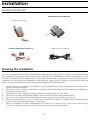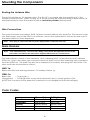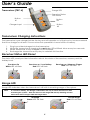
1
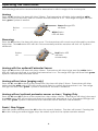
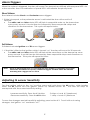
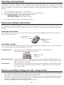
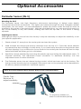
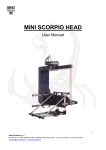
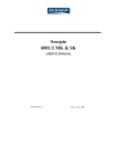
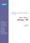
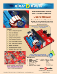
SR-C400
Motorcycle Security System
INSTALLATION MANUAL
AND USER’S GUIDE
Standard Features
•
•
•
•
•
•
•
•
•
•
•
•
•
•
FM two way transceiver
Up to ½ mile communication range
Multi-color LED panel trigger indicator
Waterproof remote transmitter
Ultra low power drain MCM
Built-in accelerometer
Ignition protection
Remote sensor control
Battery safeguard with “sleep mode”
Passive arming
Selectable arming / disarming
Integrated 125 dB multi-tone siren
Remote panic feature
Soft chirp arming
Optional Accessories
•
•
•
•
Perimeter sensor – A miniature multi stage microwave sensor that detects motion in
mass around the motorcycle.
Data Output – For future expansion.
Back-up Battery - A built-in back-up battery feature allowing the siren and transmitter to
continue operating when power is interrupted.
Factory Connector Kits–OEM style connectors that simply plug into the motorcycle’s
factory wiring harness. Connector kits are available for select motorcycle models.
Table of Contents
Installation
•
Component List ---------------------------------------------------------------•
Planning The Installation ---------------------------------------------------•
Mounting The Components ----------------------------------------------•
Color Codes --------------------------------------------------------------------•
Connections --------------------------------------------------------------------•
Using the T-tap -----------------------------------------------------------------User’s Guide
•
Transceiver Charging Instructions ---------------------------------------•
Receiver Status LED Panel --------------------------------------------------•
Range LED -----------------------------------------------------------------------•
Operating the transceiver -------------------------------------------------•
Alarm Triggers-------------------------------------------------------------------•
Adjusting G Sensor -----------------------------------------------------------•
Selecting Arming Modes ---------------------------------------------------•
Transceiver Battery -----------------------------------------------------------•
Motorcycle Battery Safe Guard -----------------------------------------Optional Accessories Instructions
•
Perimeter Sensor (SN-5) -----------------------------------------------------•
Back-up Battery ---------------------------------------------------------------•
Data output ---------------------------------------------------------------------Warranty and FCC Information
•
Limited Warranty ------------------------------------------------------------•
FCC Notice ---------------------------------------------------------------------•
Contact information --------------------------------------------------------1
Page 3
Page 3
Page 4
Page 4
Page 5
Page 5
Page 6
Page 6
Page 6
Page 7
Page 8
Page 8
Page 9
Page 9
Page 9
Page 10
Page 11
Page 11
Page 12
Page 12
Page 12
Installation
Components List
MCM (Main Control Module)
Remote Transceiver
Generic Instillation Kit (GEN-1a)
Main Harness (HAR-1a)
Planning the Installation
It is very important that before starting the installation of the security system, you carefully read
the installation instructions and spend time planning the installation. By planning ahead you will
be able to select the best approach in placing, securing and wiring the system to your specific
motorcycle. Although the installation is not difficult, there are a number of steps that must be
taken for the system to operate properly. We suggest the following steps:
1.
2.
3.
4.
5.
6.
7.
Check that your motorcycle battery is fully charged and that all electrical circuits are in
good working condition.
Check the layout and construction of the motorcycle to decide what space is available to
place the components.
Verify that no moving parts interfere with the components or their wires.
Do not route wires near sharp edges, which could cut wires and cause a short.
Do not mount components near extreme heat areas such as exhaust pipes etc.
Allow at least an inch or two of slack at all connection points to reduce the chance that a
connection will break apart due to vibration.
Select a suitable location underneath the seat or in a side cover. Mount the MCM using
Velcro or cable ties. Make sure that it is not exposed or easily reached.
2
Mounting the Components
Routing the Antenna Wire
The MCM includes an 18” antenna wire. The first 12” is a coaxial wire; the remaining 6” is the
reception antenna wire. When routing, try to avoid running the antenna along or near metal. For
best performance, have the antenna wire as vertical as possible and exposed.
Wire Connections
The system includes one harness (HAR-1a) that connects directly into the MCM. The harness is split
into three plugs: one for the GEN-1a connector, one for the optional SN-5 connector and one for
the data output for future expansion.
Note:
Each plug is unique and will only fit the appropriate component one way.
Main Harness
Note:
If the optional factory connector kit is being used, please disregard this section of the
instructions and refer to the instructions supplied with the factory connector kit.
The main harness consists of two harnesses. One is labeled (HAR-1a) and the second is labeled
(GEN-1a). Plug in the white 4 pin connector from the (HAR-1a) into the matching 4 pin connector
from the (GEN-1a). The (HAR-1a) also has a waterproof connector that plugs into the MCM. The
wires should be connected as follows:
HAR-1a
Black wire with fuse and ring terminal – To battery Positive (+).
GEN-1a
Black wire
– To ground (-).
Orange wire – To tail light wire or any other wire that is hot (+) when ignition is ON
(NOTE: this is an input to the alarm this connection is not designed to flash the tail light).
Color Codes:
Honda
Kawasaki
Suzuki
Yamaha
Harley Davidson
Ground (-)
Green wire
Black wire
Black/White
Black wire
Black wire
3
Tail Light
Brown wire
Red wire
Brown wire
Blue wire
Blue wire
Connections
To Battery (+)
Antenna
HAR-1a
*GEN-1a
Plug
SN-5
Plug
DATA
Plug
MCM
* If an Optional Factory connector is used then that would be used in place of the GEN-1a.
Note: Connect the (HAR-1a) harness to the MCM only after installation is completed. If the
battery is to be removed, disconnect this connector first. Reconnect only after battery
terminals are reconnected.
Note: When the main harness (HAR-1a) is plugged in, the siren should chirp. If the siren dose
not chirp; check the fuse, and battery (+) and ground (-) connections.
Using the T-tap Connectors
1) Place female T-tap connector over wire to be tapped, close and squeeze until it snaps.
2) Now slip male T-tap connector over hinged end of the female connector.
Motorcycle Wire
1)
Female T-tap
2)
Female T-tap
Male T-tap
Motorcycle
Wire
Wire from (GEN-1a)
4
User’s Guide
Transceiver (TRC-4)
Range LED
Receiver Status
LED Panel
Button
#1
Button
#2
Charger Input
Button
#3
Transceiver Charging Instructions
The transceiver is pre-charged at the factory and will operate out of the box but we recommend
that it be charge for at least 10 hours when first operated to insure full life of battery.
1.
2.
3.
4.
Plug in provided charger into the transceiver.
While the transceiver is charging the red status LED will flash twice every two seconds.
When transceiver is fully charged no LED will flash.
Recharge the transceiver every day to maintain full function.
Receiver Status LED Panel
The status LED panel provides information about the status of the receiver, memory and the
battery level.
Receiver On
White LED will flash
Receiver on / Low Battery
Red LED will flash.
Receiver on / Memory Trigger
Blue LED will flash
Range LED
Range LED indicates when the transceiver is still with in receiving range of the system.
Note:
To conserve battery, the Range confirmation will only work for the first hour after
activating the system. After the first hour the range LED will stop flashing and the
transceiver will no longer indicate range status
In Range
Green LED will flash
Out Of range
Red LED will flash
5
Operating the transceiver
The following instruction assumes that the transceiver is with in range of the motorcycle.
Arming
Press the #1 button, the siren will chirp 3 times. The transceiver will chirp twice and the white
status LED will continuously flash to confirm that the receiver is on. The range LED light will then
flash green. System is armed.
Green Range LED
will flash
Button
#1
White Status
LED will flash
Disarming
Press the #2 button, the siren will chirp once. The transceiver will sound once followed by another
long chirp. The red status LED will turn ON momentarily and the receiver will shut off. System is
disarmed.
Button
#2
Red Status LED
will flash
momentarily
Arming with the optional Perimeter Sensor
Press the #3 button, the siren will chirp 4 times. Transceiver will chirp twice and the white status
LED will continuously flash to confirm the transceiver is on. The range LED light will then flash green.
System is armed with perimeter sensor
Arming without siren (paging only)
Press the #1 and #3 buttons at the same time, the siren will chirp 5 times. Transceiver will chirp
twice and the white status LED will continuously flash to confirm the transceiver is on. The range
LED light will then flash green. System is armed but the siren is disabled.
Arming without optional perimeter sensor or siren / Paging Only
Press the #2 and #3 buttons at the same time, siren chirps 4 times. Transceiver will chirp twice and
the white status LED will continuously flash to confirm the transceiver is on. The range LED light will
then flash green. System is armed but the Perimeter Sensor and siren are disabled.
Panic/ Stop Trigger
With the system armed press the #3 button for a panic feature. The siren will sound. Pressing the
#3 button during an alarm trigger stops the alarm cycle but the system remains armed.
6
Alarm Triggers
When the system is triggered, the siren will sound. The transceiver will flash all three panel LED’s for
a few seconds, then a combination of panel LED’s will indicate the priority level:
Short Alarm
Short Alarm includes Shock and Perimeter sensor triggers.
1. If bike is bumped, or the perimeter sensor is activated the siren will sound for 5
seconds.
•
The white, red and blue status LED will flash in sequential order on the transceiver
once every second. It would then be followed by three sequential chirps and
vibrations on the transceiver. This cycle will repeat twice.
Full Alarm
Full Alarm includes Ignition and Tilt sensor triggers.
1. If the bike is tilted or the ignition switch is turned “on” the siren will sound for 30 seconds.
•
The white, red and blue status LED will flash at the same time on the transceiver once
every second. It would then be followed by three sequential chirps and vibrations on
the transceiver. This cycle will repeat six times.
Note:
Once an alarm trigger has occurred and the siren duration is completed, the system
will remain armed and accept any additional triggers. The Blue status LED will flash
indicating that a trigger has occurred.
Adjusting G sensor Sensitivity
Turn the ignition switch to the “on” position, press and hold down the #3 button, while holding
down the #3 button turn the ignition switch off, release button #3. The siren will chirp to
correspond with the current sensitivity setting.
-Increase sensitivity- Press the #1 button
-Decrease sensitivity- Press the #2 button
5 chirps = Level # 5 (Maximum)
1 chirp = Level #1 (Minimum
To save the changes and exit sensitivity adjusting, press button #3. To exit with out saving
changes, turn ignition “on” and back “off”.
7
Selecting Arming Modes
The system offers two arming modes. Manual arming will require the user to activate the alarm
when ever is needed. The Auto arming mode will activate the alarm automatically 60 seconds
after the ignition is turned off. The system is preset to manual arming mode, to change to auto
arming
1.
2.
3.
Turn the ignition switch to the” on” position.
Press and hold the #1 button until the siren chirps, then release.
The current arming mode is indicated by the siren
-Manual arming- siren chirps 2 times.
-Automatic arming- siren chirps 3 times.
4.
To change back to previous setting repeat #2
Transceiver Battery Information
The receiver is automatically turned on when ever the system is armed. To conserve battery the
transceiver should be turned off when not in use, or when it’s out of range for extended periods
of time.
Powering off receiver
Press and hold the #2 button until the transceiver chirps and the red panel LED turns on and off.
The receiver is turned off.
Press and hold
Button #2
Red Status LED
will flash
momentarily
Low Battery Stages
It’s recommended that the transceiver be charged daily when in regular used. If the transceiver
is not charge daily the following stages will occur.
Low Battery LED:
The battery is low the red status LED will flash. The transceiver
should be charged as soon as possible.
Red Status LED
will flash
Receiver Turns Off: If the transceiver is not charged, at some point (approximately 7 days) the
receiver will shut off. At this stage the receiver will keep shutting down every
time the system is armed.
No response:
If the battery is not recharged and all power is drained. The transceiver will
not respond. The transceiver has to be fully charged before it can operate
the system again.
Motorcycle Battery Safeguard with “sleep mode”
•
•
•
If the optional perimeter sensor is being used and the alarm is armed for more then 10 days
the system will automatically disable the perimeter sensor.
If the alarm is armed for more than 30 days, the system will automatically disable the systems
receiver. In this mode the transceiver will no longer be able to operate the system but the
system is still armed and protecting the bike.
To disarm, trigger the alarm, and press the #1 button.
8
Optional Accessories
Perimeter Sensor (SN-5)
Mounting the SN-5
The Perimeter sensor uses high frequency microwave technology to detect mass density
movement around the motorcycle. The signal can transmit through the seat, fiberglass, leather
and plastic, but not metal. It is recommended to place this sensor under the seat as close as
possible to the center of the motorcycle. With the provided Velcro, you can mount this sensor on
top of the battery or any flat surface, making sure that the top side of the sensor is facing
upwards.
Adjusting the Sensor
Although the sensor is pre set from the factory it may be necessary to adjust the sensitivity to suit
your specific application.
1.
Stand at least 10’ away from the motorcycle and arm the system.
2.
Walk towards the motorcycle and try and lean over the top of it. Once the sensor detects
movement the siren will begin to chirp slowly. If you back away from the motorcycle the siren
will stop chirping. If you continue to move closer to the motorcycle the siren will start to chirp
faster and faster and then go into a full alarm.
3.
Sensitivity can be adjusted by removing the plastic cap and tuning the adjustment screw. To
increase sensitivity, turn adjustment screw clockwise. To decrease sensitivity, turn the
adjustment screw counter clockwise.
4.
The Perimeter sensor has an internal tuning control, which has been set at the factory. This
tuning control should only be changed if the sensor can not be properly set as described in
#3 above, please call Aritronix’ technical support.
Note: Do not turn sensitivity above half way. Doing so may cause false alarms.
Plastic Cap :
Remove to
adjust sensitivity
To Accessory Harness on
Main Control Module (MCM)
9
Back-up Battery
The back-up battery provides the system the ability to transmit information and activate the siren
when power is interrupted. If power is ever interrupted while the system is activated the back-up
battery will be engaged, the transceiver will receive a full alarm and the siren will sound in 25
second increments. If power is not restored the alarm will continue to transmit and sound for six
cycles.
Note:
The system has to be correctly installed for at least 12 hours before full function of the
back-up battery can be used.
To check the status of the back-up battery active the system using button #1.
•
If the Alarm chirps 3 times the back-up battery is in good working condition
•
If the system chirps 2 times the back-up battery is not fully charge.
Note:
If the system chirps only 2 times and it has been correctly connected for more the 12
hours the battery needs replacement. (Contact Aritronix for replacement options)
Data output
A data output has been included with this system for future expansion.
This section purposely left blank
10
Limited Warranty
Scorpio-branded security products come with a 2-year (from time of purchase) limited
warranty. This includes all components and accessories that are manufactured by
Aritronix Ltd. The following sections describe the limited warranties.
What is covered by this limited warranty?
This limited warranty covers defects in materials and workmanship in your — our end-user
customer's — Scorpio-branded hardware products, including Scorpio-branded
accessory products.
What is not covered by this limited warranty?
This limited warranty does not cover cosmetic damage, damage/failure due to acts of
God: Problems that result from:
•
•
•
•
External causes such as accident, abuse, misuse, or problems with electrical power.
Usage that is not in accordance with product instructions or modifications of the
product.
Failure to follow the product instructions.
Problems caused by using accessories, parts, or components not manufactured or
approved by Scorpio.
What should you do if you experience a problem with a Scorpio product?
First contact Aritronix, Ltd. using one of the methods listed below. [Proof of purchase,
installer and motorcycle information will be requested]. If after assistance from our
trained staff it is determined that the Scorpio product may be faulty then you will provide
with detailed information on processing a warranty claim. All warranty claims must
contain a return authorization number (RA#). Aritronix, Ltd. will not accept any package
that does not have been approved for warranty repair/exchange.
Shipping and Handling
If a warranty claim is requested and approved a standard shipping and handling
charge will apply. All charges have to be paid before package is returned back to
customer.
FCC Notice
This device complies with Part 15 of FCC rules. Operation is subject to the following two
conditions: (1) This device may not cause harmful interference, and (2) This device must
accept any interference that may cause undesired operation.
Changes or modifications not expressly approved by the party responsible for
compliance could void the user’s authority to operate this device.
For technical assistance with any of the procedures on this manual, or for warranty claims
please contact Aritronix at:
www.scorpioalarms.com
[email protected]
Toll Free
(800)428-0440
International
(480)951-1109
Aritronix Ltd
16055 N. Dial Blvd. B-10
Scottsdale, AZ 85260