1
Scorpio
6001/2 MK & SK
USER'S MANUAL
0311375 Rev C
Issue : June 1999
FCC statement (USA)
The United States Federal Communications Commission (in 47 CFR 15.105) has specified that the
following notice be brought to the attention of users of this product:
This equipment has been tested and found to comply with the limits for a Class B digital device,
pursuant to part 15 of the FCC Rules. These limits are designed to provide reasonable protection
against harmful interference in a residential installation. This equipment generates, uses and can
radiate radio frequency energy and, if not installed and used in accordance with the instructions,
may cause harmful interference to radio communications. However, there is no guarantee that
interference
will not occur in a particular installation. If this equipment does cause harmful interference to
radio or television reception, which can be determined by turning the equipment off and on, the
user is encouraged to try to correct the interferences by one or more of the following measures:
- Reorient or relocate the receiving antenna.
- Increase the separation between the equipment and the receiver.
- Connect the equipment into an outlet on a circuit different from that to which the receiver
is connected.
- Consult the dealer or an experienced radio/TV technician for help.
The user may find the following booklet, prepared by the Federal Communications Commission,
helpful: How to identify and Resolve Radio/TV Interference Problems. This booklet is available
from the U.S. Government Printing Office, Washington, DC. 20402 , Stock No. 004-000-00345-4.
Use of a shielded cable is required to comply within Class B limits of Part 15 of FCC Rules.
Pursuant to Part 15.21 of the FCC Rules, any changes or modifications to this equipment not
expressly approved by DSNP may cause harmful interference and void the FCC authorization to
operate this equipment.
DSNP makes no warranty of any kind with regard to this equipment, including, but not
limited to, the implied warranties of merchantability and fitness for a particular purpose. DSNP
shall not be liable for errors contained herein or for incidental consequential damages in
connection with the furnishing, performance, or use of this equipment
This manual contains proprietary information which is protected by copyright. All rights are
reserved. No part of this document may be photocopied, reproduced or translated into another
language without the prior written consent of DSNP.
The information contained in this manual is subject to change without notice.
Scorpio 600x xK Series User’s Manual
How to use this Manual
How to use this Manual
-
Section 1 covers equipment unpacking and description for
both base station and rover unit.
-
Section 2 tells you how to prepare a project using the KISS
software.
-
Section 3 provides all the instructions required to install
and run a base station.
-
Section 4 contains all the information required to prepare
the rover unit and use it in the field. This section is the
reference documentation for the field operator.
-
Section 5 tells you how to download the data contained in
the PCMCIA after your field operations, using the KISS
software.
-
Appendix A is a short introduction to the GNSS system.
-
Appendix B reviews all the products of the Scorpio 6000
series.
-
Appendix C presents the theory of operation of the LRK
and KART processing methods.
-
Appendix D is the reference documentation for the Station
Control Software, a palmtop-run, user-interface program
used at the base station.
Scorpio 600x xK Series User’s Manual
How to use this Manual
-
Appendix E describes the notation rules used in the SBIN
and SVAR formats.
-
Appendix F describes the GPS raw data available in the
SBIN format.
-
Appendix G describes the results files(SVAR format).
-
Appendix H collects useful information for the
troubleshooting of the system. Software installation is also
described.
Scorpio 600x xK Series User’s Manual
Table of Contents
Table of Contents
1. Unpacking & Description .................................................1-1
6001/2 MK Rover Unit ................................................................. 1-1
Unpacking...................................................................................... 1-1
6001/2 SK Base Station .............................................................. 1-5
Unpacking...................................................................................... 1-5
GNSS receiver description .......................................................... 1-8
Front Panel .................................................................................... 1-8
Rear panel ................................................................................... 1-10
PCMCIA Drive ........................................................................... 1-11
Inserting a PCMCIA card ............................................................. 1-11
Removing a PCMCIA card........................................................... 1-12
FSGS Palmtop Computer ......................................................... 1-13
FSGS Battery Pack...................................................................... 1-13
FSGS temperature ranges........................................................... 1-14
Environment ................................................................................ 1-14
Trickle-charged internal battery ................................................... 1-14
Cleaning ...................................................................................... 1-14
Long-term storage ....................................................................... 1-14
After long-term storage................................................................ 1-15
Changing the NiCd battery .......................................................... 1-15
Preparing batteries for the Rover Unit....................................... 1-16
2. Preparing a project...........................................................2-1
Introduction.................................................................................. 2-1
Creating a project ........................................................................ 2-1
Terminology used........................................................................ 2-7
DSNP
i
Scorpio 600x xK Series User’s Manual
Table of Contents
Placing reference points on the map........................................... 2-8
Placing target points on the map............................................... 2-10
Preparing PCMCIA cards for field operators............................. 2-13
3. Operating Instructions at the base station......................3-1
Station installation ....................................................................... 3-1
Choosing a location where to install a base station....................... 3-1
GPS antenna ................................................................................. 3-1
UHF antenna ................................................................................. 3-2
Connections and Setup ............................................................... 3-2
Measuring the GPS antenna height ............................................ 3-4
DSNP measurement...................................................................... 3-4
USER measurement...................................................................... 3-5
Programming the base station (Quick Procedure)...................... 3-7
Preamble ....................................................................................... 3-7
Getting the Palmtop software started ............................................ 3-8
Programming steps ....................................................................... 3-8
4. Operating Instructions on the Rover Unit ........................4-1
Preparing for a field survey ......................................................... 4-1
Assembling the various parts ........................................................ 4-1
Connections................................................................................... 4-3
Getting ready for surveying............................................................ 4-4
Introduction to Palmtop Software ................................................ 4-4
Palmtop Display............................................................................. 4-5
Keys and menus............................................................................ 4-5
Getting started............................................................................. 4-9
About jobs and files ..................................................................... 4-11
Choosing a job............................................................................. 4-11
Choosing a file............................................................................. 4-14
Checking operating conditions before starting a survey.............. 4-15
Surveying target points (Staking Out) ....................................... 4-16
ii
DSNP
Scorpio 600x xK Series User’s Manual
Table of Contents
General case ............................................................................... 4-16
Surveying target points through offset procedure........................ 4-26
Logging points ........................................................................... 4-34
General case ............................................................................... 4-34
Logging points through offset procedure ..................................... 4-36
Surveying a trajectory................................................................ 4-43
Surveying reference points........................................................ 4-46
Guidance along a profile ........................................................... 4-47
Refining the coordinate system by surveying reference points . 4-51
Refining the horizontal system (local grid)................................... 4-52
Computing the vertical system (height correction) ...................... 4-56
Ancillary procedures .................................................................. 4-59
Working on the results of the job................................................. 4-59
Measuring the distance between any two points ......................... 4-61
Configuring the "next point" ......................................................... 4-63
"Search" function ......................................................................... 4-64
Creating a point ........................................................................... 4-64
Creating a line ............................................................................. 4-66
Viewing points on a plane (2D view)............................................ 4-69
Recording Raw Data on PCMCIA................................................ 4-71
UHF receiver setting & base station identification ....................... 4-72
Viewing the solution of your current position ............................... 4-74
Viewing the status of the GPS constellation ................................ 4-75
Rejecting satellites....................................................................... 4-77
Processing & initialisation modes ................................................ 4-78
Viewing the datum and projection used....................................... 4-81
Switching to WGS84.................................................................... 4-82
Using the notepad ....................................................................... 4-83
Free memory space on PCMCIA and Palmtop, deleting geodesy
description files............................................................................ 4-85
Tools box................................................................................... 4-87
Viewing the versions of the system's hardware parts .................. 4-87
Editing Time & Date..................................................................... 4-87
Editing Geocodes ........................................................................ 4-88
DSNP
iii
Scorpio 600x xK Series User’s Manual
Table of Contents
Editing uncertainties, acceptable deviation & battery alarm
threshold...................................................................................... 4-89
Measuring the surface of an area ................................................ 4-90
Editing Units ................................................................................ 4-94
Using the palmtop in standalone mode ..................................... 4-94
5. Downloading field data....................................................5-1
Introduction.................................................................................. 5-1
Collecting the results of a survey ................................................ 5-1
Graphic Conventions................................................................... 5-3
Before surveying............................................................................ 5-3
After surveying............................................................................... 5-3
Editing a point surveyed at the planned location ......................... 5-5
Editing a logged point .................................................................. 5-8
Editing a planned point surveyed through offset procedure ........ 5-9
Offset Tab .................................................................................... 5-10
P1, P2, P3 or P4 tab .................................................................... 5-11
Editing a logged point surveyed through offset procedure ........ 5-12
Exporting results in the desired format...................................... 5-13
Saving PCMCIA files on your computer .................................... 5-14
Post-processing the raw data collected during a job................. 5-14
iv
DSNP
Scorpio 600x xK Series User’s Manual
Appendices
Appendices
A. Introduction to GNSS ....................................................... A-1
GPS Constellation .......................................................................A-1
Signals.........................................................................................A-2
Navigation Message....................................................................A-3
GNSS ..........................................................................................A-3
GENERAL DESCRIPTION ............................................................ A-3
Purpose ......................................................................................... A-4
GNSS concept ............................................................................... A-5
The different systems .................................................................... A-6
B. Introduction to the DSNP Scorpio 6000 series.................B-1
Preamble .....................................................................................B-1
The heart of your equipment .......................................................B-2
Operating environment................................................................B-2
The clues to product naming in the Scorpio 6000 Series............B-2
Product applications ....................................................................B-3
Product Selection Guide..............................................................B-4
Specifications ..............................................................................B-5
Physical ......................................................................................... B-5
Electrical ........................................................................................ B-5
Environmental................................................................................ B-6
Receiver unit standard features..................................................... B-6
Built-in UHF receiver (for 600x MK) ............................................... B-6
Plug-in UHF transmitter (for 600x SK) ........................................... B-7
6001 MP/6001 SP specific performance data.............................B-7
DSNP
v
Scorpio 600x xK Series User’s Manual
Appendices
6002 MP/6002 SP specific performance data.............................B-7
6001 MK/6001 SK specific performance data.............................B-8
6002 MK/6002 SK specific performance data.............................B-8
Block Diagrams ...........................................................................B-9
6001 MP & 6001 SP ...................................................................... B-9
6002 MP & 6002 SP .................................................................... B-10
6001 MK Rover Unit .................................................................... B-11
6001 SK Base Station ................................................................. B-12
6002 MK Rover Unit .................................................................... B-13
6002 SK Base Station ................................................................. B-14
C. KART/LRK General Principles ..........................................C-1
KART...........................................................................................C-1
Theory of operation........................................................................C-1
Characteristics...............................................................................C-3
LRK .............................................................................................C-4
D. Base Station Control ........................................................ D-1
Introduction to Palmtop software.................................................D-1
Palmtop display .............................................................................D-1
Keys and menus............................................................................D-1
Getting started.............................................................................D-6
Station Control.............................................................................D-8
Antenna .........................................................................................D-8
Position..........................................................................................D-9
Transmitter ..................................................................................D-12
Average position..........................................................................D-13
File Management.......................................................................D-15
Memory........................................................................................D-15
Raw Data .....................................................................................D-17
Sessions ......................................................................................D-18
Notes ...........................................................................................D-22
vi
DSNP
Scorpio 600x xK Series User’s Manual
Appendices
SVs............................................................................................D-24
Visible Constellation ....................................................................D-24
Deselection..................................................................................D-26
Coordinate System Used ..........................................................D-27
Datum ..........................................................................................D-27
Projection.....................................................................................D-28
Change to WGS84 ......................................................................D-28
Load Geodesy .............................................................................D-29
Local Grid ....................................................................................D-30
Height correction .........................................................................D-31
System Tools.............................................................................D-32
Time.............................................................................................D-32
Configuration ...............................................................................D-33
Unit ..............................................................................................D-33
Release .......................................................................................D-33
E. Notation rules used in SVAR and SBIN formats ...............E-1
SVAR...........................................................................................E-1
Reserved characters ..................................................................... E-1
Conventions used.......................................................................... E-1
General form.................................................................................. E-2
Rule about numerals ..................................................................... E-2
Rule about labels........................................................................... E-3
Error check rule ............................................................................. E-3
SBIN ............................................................................................E-4
Reserved characters ..................................................................... E-4
Conventions used.......................................................................... E-5
Symbols used ................................................................................ E-5
General form.................................................................................. E-5
Error check rule ............................................................................. E-6
Rule about numerals ..................................................................... E-6
F. GPS Raw Data in SBIN format ........................................... F-1
SBIN@R : Single-frequency GPS pseudoranges in satellite timeF-1
DSNP
vii
Scorpio 600x xK Series User’s Manual
Appendices
SBIN@R : Dual-frequency GPS pseudoranges in satellite time . F-4
SBIN@A: Almanac data .............................................................. F-9
SBIN@E: Ephemeris data......................................................... F-10
SBIN@U: Iono/UTC data .......................................................... F-11
SBIN@S: Health & A/S data ..................................................... F-11
G. Results files in ASCII SVAR format...................................G-1
File Header................................................................................. G-1
Points list .................................................................................... G-2
Kinematic re-initialization............................................................ G-8
Datum......................................................................................... G-9
Projection parameters ................................................................ G-9
Tangent conical projection (Lambert): .........................................G-11
Secant conical projection (Lambert) ............................................G-12
UTM projection (Universal Transverse Mercator) ........................G-13
Oblique cylindrical projection (Skew Orthomorphic) ....................G-14
Oblique cylindrical projection (Rectified Skew Orthomorphic) .....G-15
Oblique stereographic projection (Skew Stereographic) .............G-16
Altimetric parameters ............................................................... G-17
Unit code .................................................................................. G-18
RES file example (extracts)...................................................... G-19
H. Troubleshooting &Software Installation.......................... H-1
GNSS Receiver Status Display ...................................................H-1
Introduction....................................................................................H-1
Screen No.0: Operating Status......................................................H-2
Screen No. 1: Error report .............................................................H-3
Screen No. 2: Position solution .....................................................H-4
Screen No. 3: Time information .....................................................H-5
Screen No. 4: GNSS reception status ...........................................H-5
Screen No. 5: Information about sessions.....................................H-6
viii
DSNP
Scorpio 600x xK Series User’s Manual
Appendices
Screen No. 6: Information about corrections .................................H-7
Screen No. 7: Differential corrections............................................H-8
Screen No. 8: Firmware installed...................................................H-9
Screen No. 9: Hardware and Software identification ...................H-10
GNSS Receiver Front Panel Indicators.....................................H-11
GNSS Receiver Error report......................................................H-11
Error families ...............................................................................H-12
Error classification .......................................................................H-12
Error list .......................................................................................H-13
GNSS Receiver Rear panel Connectors ...................................H-16
RS232 cable ................................................................................H-19
FSGS Palmtop Computer .........................................................H-20
FSGS Palmtop Configuration ......................................................H-20
Software loading ..........................................................................H-21
Maintenance steps ......................................................................H-23
DSNP
ix
Scorpio 600x xK Series User’s Manual
Appendices
x
DSNP
Unpacking & Description
6001/2 MK Rover Unit
1. Unpacking & Description
6001/2 MK Rover Unit
Unpacking
1
The supply consists of a container and a telescopic pole provided
separately.
Telescopic Pole 1337-L,
Part No. 3310203
Open the container. This item, marketed
under the Part No. 790077805, includes the
container as such + the inner foam trays used
to secure the various parts in the container.
List and inspect all the parts provided. Should
parts be missing or damaged when first
opening the container, please contact your distributor. DSNP
reserves the right to make changes to the standard supply described
below without prior notice.
DSNP
1-1
1
Unpacking & Description
6001/2 MK Rover Unit
FSP70, 0 dB flexible UHF antenna
3310190 (415/435 MHz)
or 3310196 (430/450 MHz)
or 3310188 (450/470 MHz)
Quick release adapter
Part No. 26I2076528
GPS antenna:
NAP001 (L1) Part No.26E1076311 or
NAP002 (L1/L2) Part No. 26E1076208
with 5/8" adapter Part No. 724076577
FS/GS
palmtop
computer and
internal battery
Part No.
317076375
Palmtop
support for
telescopic
pole, Part No.
7510423
FS/GS palmtop cable, pp/SubD Part No. 605076501, 1.0 m
FS/GS-PC cable, SubD9/SubD9 Part No. 605076502, 1.0 m
GPS coaxial cable (pp/TNCm) Part No. 505076500, 1.5 m
UHF coaxial cable (TNCm/TNCm) Part No. 5050227, 2.50 m
Mast for UHF antenna Part No.
26I2076840
(includes UHF
coaxial cable
Part No. 505076499)
+ Mast for GPS antenna
Part No. 26I2076564 (not visible
on the photo)
1-2
DSNP
Unpacking & Description
6001/2 MK Rover Unit
Battery Charger
Part No. 3440005
Shoulder straps and belt,
Part No. 751076678 Receiver
Receiver holder
(black) Part No.
751076466
2 NiCd
Battery packs
Part No.343088
1
1 PCMCIA Card
Part No. 4660039
Rover unit assembly
Part No.26I2076548
1 Scorpio Software
CD-ROM
User's Manual
Part No. 0311375
Metal Support
Part No. 751076467
Battery compartment
Part No. 26I2076679
+ Bag of clips
Part No. 7870088
The rover unit assembly (Part No. 26I2076548) consists of the
following parts:
DSNP
-
the 6001 receiver Part No. 26I1076437or 6002 receiver
Part No. 26I2076433
-
the stand, Part No. 26E1076942, which consists of the
receiver holder (Part No. 751076466, black rubber), the
Metal support (Part No. 751076467) and small parts
(screws, washers, standoffs).
-
the battery compartment, Part No. 26I2076679 (which
includes 2 battery cables Part No. 605076507)
1-3
1
Unpacking & Description
6001/2 MK Rover Unit
-
Shoulder straps and belt, Part No. 751076678, including a
serial line cable (605076509, 0.75 m) and a GPS antenna
cable (605076510, 0.75 m, coaxial, 50 Ω).
Note the presence of two cables in the belt at delivery. Do not
remove them as they are precisely required at this location for your
field surveys.
They do not need to be removed either when putting the rover unit
assembly back into its container for transportation.
1-4
DSNP
Unpacking & Description
6001/2 SK Base Station
6001/2 SK Base Station
Unpacking
The standard supply consists of the following items (DSNP reserves
the right to make changes to this list without prior notice):
- GPS station kit Part No. 26E1076434 (adapters, Meter Kit,
and other small parts)
- Station container Part No. 790077806 (consists of the
container as such + the inner foam trays used to secure
the various items in the container):
-
1
Receiver holder Part No. 751076466 (black rubber) and
metal support Part No. 751076467:
Receiver holder
Part No.
751076466
(black rubber)
Metal support
Part No.
751076467
DSNP
1-5
1
Unpacking & Description
6001/2 SK Base Station
UHF antenna whip
(from GP450-3
antenna
Part No. 3310202)
Ground plane
(from GP450-3 antenna
Part No. 3310202)
UHF antenna mast
element, 50 cm
Part No.735076661
Adapter assembly
composed of:
• GAW600
Tripod adapter
Part
No.3310205
• GAF 5/8"
adapter
Part No.
3310206
FMP40 antenna
mount kit
Part No. 3310115
GPS antenna:
NAP001 (L1) Part No.26E1076311
or
NAP002 (L1/L2) Part No. 26E1076208
with
5/8" adapter Part No. 724076577
Allen wrench
(for assembling the
UHF antenna)
Meter Kit (2 parts)
Part No. 26I2076601
Set of cables:
1 power cable, 2 m
1 RS232C cable, 2m
1 × 10-metre GPS coaxial cable (TNC-m/TNC-m)
1 × 6.50-metre UHF coaxial cable (N-m/N-m)
1-6
Part No. 605076503
Part No. 605076570
Part No. 5050196
Part No. 5050197
DSNP
Unpacking & Description
6001/2 SK Base Station
Receiver Part No. 26H1076468
or
Receiver Part No. 26H2076469
Plug-in UHF
transmitter
Part No. 26E1075203
Receiver holder
Part No.
751076466
(black rubber)
1
Metal support
Part No.
751076467
Station stand Part No. 26E1076942 consists of the
receiver holder, the metal support and small parts (screws, washers,
standoffs).
DSNP
1-7
1
Unpacking & Description
GNSS receiver description
GNSS receiver description
The GNSS receiver used both at the base station and as the rover
unit is fitted with the following parts on its front and rear panels.
Front Panel
• Front panel controls
ON/OFF push-button : used to switch the receiver ON (brief
press) or OFF (long press)
The indicator light nested in this button
starts blinking when you press the button
(if the receiver is connected to a power
source). From the end of the self-tests, the
light is permanently ON.
Scroll push-button : used to access the different data screens
available from the status display.
Activates the screen light for 30 seconds
whenever depressed.
A long press on the Scroll push-button
allows you to return to screen No. 0.
- If the receiver is used as a rover unit, the
indicator light nested in the button provides
the following information:
ON : Data recording on PCMCIA in
progress
OFF : No data recording
- If the receiver is used at a base station, the
indicator light nested in the button provides
information about the possible planned
sessions or session in progress as soon
as you connect the receiver to the power
source:
1-8
DSNP
Unpacking & Description
GNSS receiver description
Blinking : A session is programmed to be
run at a later time & date.
A few minutes before starting the
session, the receiver will be
automatically turned on, unless
meanwhile this is made manually
by the operator (who presses the
ON/OFF button) or unless the
power supply mode has been set
to "MPW" (refer to Appendix D
for more information about this
parameter).
ON : An operating or recording
session is in progress. The other
indicator light is necessarily ON.
OFF : No pending session. The
receiver will be powered only
manually by using the ON/OFF
button.
Status Display : 2-line×16-character display providing
information about receiver operation (for a
complete description of the displayed data,
see Appendix H).
1
Status Display
ON/OFF
push-button
& light indicator
PCMCIA
card reader
Scroll push-button
& light indicator
DSNP
1-9
1
Unpacking & Description
GNSS receiver description
• PCMCIA card reader
A PCMCIA card reader is located in the left-hand part of the front
panel.
This device has reader/recorder capabilities.
The PCMCIA card is seen from the DSNP GNSS engine as a
conventional serial port (port P).
Rear panel
The rear panel is fitted with the following connectors:
1-10
-
A GPS coaxial connector (GPS antenna input), TNCfemale type
-
A DGPS coaxial connector (DGPS antenna input), TNCfemale type
-
Two RS232 connectors (port A named "COMPUTER"; port
B named "I/O")
-
An RS422 connector (port D named "DGPS"), 15-C SubDfemale type, used to connect the plug-in UHF transmitter
(base station only)
-
Two POWER connectors in parallel. This allows the
receiver to be maintained in operation while you swap the
power source. For example, in the case of a batterypowered receiver, you can connect the new battery before
removing the low one.
DSNP
Unpacking & Description
PCMCIA Drive
PCMCIA Drive
Inserting a PCMCIA card
-
Unlock the cover by applying a finger on its upper-middle
part and then by pushing it. The cover will open when you
remove your finger.
-
Orient the PCMCIA card as shown below.
-
Insert the PCMCIA in the slot and push gently until you
hear a click (indicating that the card is locked in the
reader).
1
Arrow on PCMCIA
-
DSNP
Close the cover (a click indicates that the cover is locked)
by pushing the cover, in the same way as you did
previously to open it.
1-11
1
Unpacking & Description
PCMCIA Drive
Removing a PCMCIA card
1-12
-
Unlock the cover.
-
With a finger, depress the black, square-shaped, knob
located to the right of the reader until the card is released.
-
Take the card out of the reader.
DSNP
Unpacking & Description
FSGS Palmtop Computer
FSGS Palmtop Computer
1
FSGS Palmtop
Warning!
Do not use
Alkaline cells
NiCd Battery Pack
Battery Cap
FSGS Battery Pack
The FSGS has been configured in order that battery charging can
take place from a power source present on its RS232C connector.
After connecting a non-powered FSGS to an operating (powered)
receiver, the "Charging in progress" message should appear
on the FSGS display. If not so, please refer to Appendix H.
At equipment delivery, the FSGS is fitted with a NiCd battery pack so
there is no particular precaution to be taken. If later, for any reason,
alkaline cells have been placed inside the palmtop, the first thing you
will have to do before using the palmtop attached to the receiver will
be to replace these cells with the NiCd pack.
Warnings!
To avoid pressurization problems inside the FSGS if it is taken on an
airline trip, the battery cap has been loosened before shipment. Do
not forget to lock this cap as this is required to maintain proper
sealing. If you have to travel by air with your equipment, do the same
(loosen the cap before take-off, lock it back after landing).
Do not charge the NiCd battery pack outside the 5 to 40°
temperature range.
DSNP
1-13
1
Unpacking & Description
FSGS Palmtop Computer
FSGS temperature ranges
-
Operating: – 20°C to +55°C
-
Storage: – 30°C to +70°C
Environment
The FSGS is designed to operate in conditions of up to 90% relative
humidity. The internal humidity indicator strip, visible in the bottomright corner of the display window, should be blue. If it takes on a
pinkish color, please remove the NiCd battery and return the
palmtop to the servicing department.
Trickle-charged internal battery
A trickle-charged internal battery is fitted, which provides back-up
power to preserve the data on the RAM disk for at least 2 weeks if
the main power source (i.e. th NiCd battery) is removed. This
auxiliary battery, charged with a trickle current from the NiCd battery,
does not normally need to be replaced.
Cleaning
Clean the LCD screen with a clean cloth. Do not use solvent
cleaners or harsh detergents. If the case is very dirty, make sure the
battery cap is tight, then wash it gently under warm running water.
Leave it to dry in a warm room. Do not use forced air drying.
Long-term storage
If you intend to store the FSGS for at least 2 months, remove the
NiCd battery and fit a fresh set of 3 highest quality Alkaline cells. We
recommend storage at a temperature between 10°C and 35°C.
Alkaline cells should be changed every 6 months.
1-14
DSNP
Unpacking & Description
FSGS Palmtop Computer
After long-term storage
Remove the Alkaline cells and insert the NiCd battery after fully
charging it.
1
Changing the NiCd battery
DSNP
-
Turn off the FSGS (press the red key, top right)
-
Use a coin to undo the battery cap (turn counter-clockwise)
-
Remove the old battery
-
Fit in a new battery, positive end first
-
Take the battery cap and, with finger pressure only, press it
into the battery compartment and turn it clockwise.
-
Only when the thread is started, use a coin to screw the
cap tightly home.
1-15
1
Unpacking & Description
Preparing batteries for the Rover Unit
Preparing batteries for the Rover Unit
-
Use NiCd batteries only.
-
Approximate charging time: from 1 hour to 1 ¼ hour per
battery
-
A single battery pack is charged at a time.
♣
1-16
DSNP
Preparing a project
Introduction
2. Preparing a project
Introduction
Preparing a project requires the use of the KISS module from the
DSNP 3SPack software package.
In this section, we will just outline the main steps of a project
preparation using this module. It is assumed that the DSNP 3SPack
software package has been properly installed and the dongle
allowing the PC to run that package has been connected to the
parallel port.
2
For detailed information on how to install 3SPack and how to use
KISS, please refer to the corresponding manual (3SPack Reference
Manual, Part No.0311366).
Creating a project
Assuming KISS is now running on your PC, do the following:
DSNP
-
or, from the menu bar select File
In the Toolbar, click
and then New, or double-click on the following icon in the
Projects window:
-
Start defining your project by completing the Project
Wizard-Welcome Dialog Box which then appears.
2-1
2
Preparing a project
Creating a project
Project
Enter the project name
Region
Enter the region name (optional)
Center Easting
Enter the Easting of the center point
Center Northing
Enter the Northing of the center point
Scale
Distances in
Choose a pre-defined value from the combo
box or type another value in the text box
Choose the distance unit from this combo box
(meters, US feet or imperial feet)
Angles In
Choose the angle unit from this combo box
(degrees or grades)
Notes text box
Add comments or recommendations of any
kind which you want to associate to this
project (optional).
-
Then, click the Next> button.
-
Complete the Project Wizard-Horizontal System Dialog
Box which then appears. In usual cases, you just have to
select a projection from the Projection combo box, which
lists all the projections available from the 3SPack
database.
If you do not know which projection should be used, select
<Unknown> in the PROJECTION combo box. As a result,
KISS will also set the ON DATUM combo box to
<Unknown>. You can however change this setting if you
know the datum.
The inverse statement is also possible: you can choose a
projection and leave the datum “<Unknown>”.
2-2
DSNP
Preparing a project
Creating a project
As you can see, all the combinations are possible.
However the most typical ones remain “projection and
datum known” or “projection and datum unknown”.
When you select a projection or datum, in fact you load it
from the 3SPack database. All the parameters of this
projection or datum then appear in the dialog box.
If necessary, you can adjust the values of some of these
parameters. If you do so, we recommend you to change
the name of the projection or datum as well (the
PROJECTION and ON DATUM combo boxes are also
editable fields). In this way, you will never forget that you
derived your horizontal coordinate system from a standard
one. WARNING! This new system will be stored in your
project only, not in the 3SPack database.
2
The different parameters of projections and datums shown
in this tab are described below.
PROJECTION Combo box listing the projections stored in the
3Spack database. Select the name of the projection
used. As a result, the rest of the dialog box is updated
to match your selection. This combo box is also an
editable text box (see above)
Proj Kind
False East.
Easting of projection center
False North.
Northing of projection center
Central Merid.
Central Lat.
Scale
DSNP
From this combo box, select the kind of
projection used. Generally this selection is
correct after you choose the PROJECTION
name (above)
Longitude of projection center
Latitude of projection center (except for 2P
Lambert)
Scale factor (except for 2P Lambert)
2-3
2
Preparing a project
Creating a project
North Lat.
Latitude of 1st parallel (for 2P Lambert only)
Ref. Lat.
Latitude of projection center (for 2P Lambert
only)
South Lat.
Latitude of 2nd parallel (for 2P Lambert only)
Skew
Azimuth of initial line (for Rect Skew Ortho
and Skew Ortho only)
ON DATUM Combo box listing the datums stored in the 3Spack
database. Select the name of the datum used. As a
result, the rest of the dialog box is updated to match
your selection. This combo box is also an editable text
box (see above)
K
Dx
X deviation from ellipsoid (signed value in m)
Dy
Y deviation from ellipsoid (signed value in m)
Dz
Z deviation from ellipsoid (signed value in m)
A
1/F
2-4
Scale factor
Semi-major axis of the ellipsoid, in m
Inverse flattening coefficient (ellipsoid)
Rx
Angular deviation around X axis of ellipsoid (in
seconds)
Ry
Angular deviation around Y axis of ellipsoid (in
seconds)
Rz
Angular deviation around Z axis of ellipsoid (in
seconds)
DSNP
Preparing a project
Creating a project
-
If a local grid must be used, proceed with the settings
below.
WITH LOCAL GRID
check button
Button cleared: no local grid
Button checked: enter the parameters of the
local grid:
E0
N0
K
DE
DN
Beta
Easting of origin
Northing of origin
Scale factor
Easting shift
Northing shift
Rotation angle
-
Then, click the Next> button.
-
Complete the Project Wizard-Vertical System Dialog Box
which then appears. In this box, tell KISS whether the
altitude of the surveyed points should be expressed in
relation to a geoid (Stanag Model) or a datum (WGS84, or
the one selected for the project). For special settings in this
dialog box, see below.
2
HEIGHT EXPRESSED ON Choose the reference upon which the
altitudes of the surveyed points will be
determined.
If you click the GEOID radio button, then the
reference can only be the Stanag model (see
combo box nearby), as this is the only geoid
model available today
If you click the DATUM radio button, then the
reference can be either the datum used in the
horizontal system, or the WGS84 (selection in
same combo box nearby)
DSNP
2-5
2
Preparing a project
Creating a project
WITH LOCAL
CORRECTION...
check button
Check this button if corrections have to be
made to the selected reference (otherwise
keep it cleared):
dH
Gl
Gg
L0
G0
Vertical deviation between vertical
system and WGS84 at the origin
Latitude gain (a coefficient)
Longitude gain (a coefficient)
Latitude of the origin
Longitude of the origin
Before you end the definition of the project, you can still go
back to the previous tabs by clicking the <Back button if
changes have to be made in these tabs. Then use the
Next> button again until the Finish button appears.
·
Once you agree with the definition of the project, click the
Finish button. KISS then creates the new project. A map
of the region of survey appears in the KISS window. In the
same time, the project is saved in the KIS directory
-
Proceed with the definition of your project as such:
1 Place your reference points on the map
(see page 2-8)
2 Place your target points on the map (see
page 2-10)
3 Write jobs to PCMCIA cards (see page 213).
2-6
DSNP
Preparing a project
Terminology used
Terminology used
The term “target” is used in two different contexts:
1. To designate a point whose location is known in theory and
which has to be materialized in the field. In this case the
term “target” is always associated with the term “point”
2. To designate the supposed (or planned) position of any
point, whether a target point or a reference point. In this
case, the term “target” is used alone. The main contexts in
which “target” appears with this meaning are:
DSNP
-
In the General tab of any dialog box describing a
reference point
-
In the General tab of any dialog box describing a
target point
-
In the Edit menu, Import Target and Export Target
commands
2
2-7
2
Preparing a project
Placing reference points on the map
Placing reference points on the map
With your project now open in the KISS window, do the following:
-
or from the Draw menu, select the
In the toolbar, click
Reference points command.
-
Move the mouse pointer (then a ) onto the map where
you want to create a new reference point.
In the lower part of the window, the status bar helps you
locate the point accurately on the map by giving the current
coordinates of the mouse pointer as you move it within the
window:
-
When the mouse pointer is at the desired location, click
with the left mouse button. This causes a dialog box to
appear in which you should complete the definition of the
point:
Name
Code 1... code 4
Keep the default name of the reference point
or type another name
Optional. Enter or select a geocode from each
of these combo boxes. The list of available
geocodes is the one you can define from the
KISS Options dialog box, General tab
Note that if you place the pointer on the downarrow of any of these combo boxes, the
meaning of the selected geocode will appear
in a tip box.
Target/Result/Error
radio buttons
2-8
At this stage, only the Target radio button is
checked as the field survey is still to come
DSNP
Preparing a project
Placing reference points on the map
E N H check buttons
They define the type of the reference point.
Three types are possible:
1D point: Obtained by checking the H
button and clearing either of the other two
buttons.
2D point: Obtained by clearing the H
button and checking either of the other two
buttons. The E and N buttons are then
checked.
2
3D point: Obtained by checking the H
button and either of the other two buttons.
All three buttons are then checked.
E N H text boxes
Notes pane:
DSNP
Planned coordinates of the reference point
resulting from where you clicked on the map.
If you change E or N, the icon will appear at a
location different from where you clicked. Any
change in these boxes should be consistent
with the type of point (1D, 2D, 3D) you choose
(see E N H check buttons just above).
Add comments or recommendations of any
kind which you want to associate to this point
(optional).
-
When the definition is complete, click the OK button. This
causes the dialog box to disappear, and a new Reference
Point icon to appear on the map:
-
Create other reference points if necessary using the same
procedure. Do not forget to save the project at regular
intervals by clicking
in the toolbar.
2-9
2
Preparing a project
Placing target points on the map
Placing target points on the map
With your project still open in the KISS window, do the following:
-
or from the Draw menu, select the
In the toolbar, click
Target points command.
-
Move the mouse pointer (now a
create a new target point.
) where you want to
In the right-lower part of the KISS window, the status bar
helps you locate the point accurately on the map by giving
the current coordinates of the mouse pointer as you move
it within the window:
-
When the mouse pointer is at the desired location, click
with the left mouse button. This causes a new Target Point
icon to appear on the map:
A default name, of the type "Target nn", is assigned to the
point. "nn" is the order number (nn=1 if first point created,
=2 if second point created, etc.).
2-10
DSNP
Preparing a project
Placing target points on the map
• Editing the properties of a target point you have just
placed on the map
or from the Draw menu, choose the
-
In the toolbar, click
Select command.
-
Double-click on the icon corresponding to the target point
you want to edit. A dialog box appears showing the
properties of the target point. At this stage, the dialog box
consists of a single tab (General).
Name
Code 1... code 4
2
Keep the default name of the target point or
type another name
Optional. Enter or select a geocode from each
of these combo boxes. The list of available
geocodes is the one you can define from the
KISS Options dialog box, General tab
Note that if you place the pointer on the downarrow of any of these combo boxes, the
meaning of the selected geocode will appear
in a tip box.
Target/Result/Error
radio buttons
E N H check buttons
At this stage, only the Target radio button is
checked as the field survey is still to come
They define the type of the target point. Two
types are possible:
. 2D point: Simply obtained by clearing
the H button.
. 3D point: Simply obtained by checking
the H button.
DSNP
2-11
2
Preparing a project
Placing target points on the map
E N H text boxes
Planned coordinates of the target point
resulting from where you clicked on the map.
If you change E or N, the icon will appear at a
location different from where you clicked. Any
change in these boxes should be consistent
with the type of point (2D, 3D) you choose
(see E N H check buttons just above).
Notes pane
Add comments or recommendations of any
kind which you want to associate to this point
(optional).
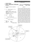
“Target” diagram
(on right)
-
2-12
The “target” (planned location) is shown at the
center of an oriented circle whose radius is
the Acceptable deviation between target
and surveyed coordinates defined in the
General tab of the KISS options.
Create other target points if necessary using the same
procedure. Do not forget to save the project at regular
intervals by clicking
in the toolbar.
DSNP
Preparing a project
Preparing PCMCIA cards for field operators
Preparing PCMCIA cards for field operators
With your project open in the KISS window, do the following:
-
Insert a card into the PCMCIA drive of your PC.
-
If you want to focus on particular points, then select the
corresponding icons. If that is not the case, do not make
any selection
-
In the toolbar, click
or, from the Transfer menu, select
the Write Job command.
-
In the Write Job... dialog box which then appears, enter a
name for the file which is going to be written to the
PCMCIA (8 characters max.) or select an existing one from
the list box which you will overwrite with the new job
-
Specify the content of the job by checking one of the
following buttons:
2
Selected Points : This option should logically be checked if
you have made a prior selection of objects
on the map (option dimmed otherwise)
Remaining Points : Check this option if you want the field
operator to deal only with the points not
surveyed yet (which supposes that a part
of the project has already been made).
With this option you do not need to make a
prior selection of objects on the map
All Points : Check this option if you want to write the
entire project to the card.
DSNP
2-13
2
Preparing a project
Preparing PCMCIA cards for field operators
-
Specify the order in which the points will be written to the
PCMCIA by making a selection in the following combo box:
In Order of Choose one of the possible ways of
arranging the points in the job:
Creation
Name
Kind
Geocode 1...4
Point size
Target East.
Target North.
Target Height
-
From the For Operator combo box, enter or select the
name of the operator in charge of the job in the field. The
list of known operators is defined in the Options dialog
box, General tab .
-
Click the OK button to write the job to the PCMCIA card.
The file extension of a job file on PCMCIA is ”JOB”.
♣
2-14
DSNP
Operating Instructions at the base station
Station installation
3. Operating Instructions at the base station
Station installation
Although installing a base station is rather an easy operation, you
should however be very careful in every detail of the installation.
Indeed, how and where you install the base station and the antennas
will greatly determine the level of performance you can expect from
it.
You do not need particular tool, but your usual tool box.
Choosing a location where to install a base station
Remember the station should be installed in a place clear of any
devices likely to produce radio-frequency interference or multipath
effects.
3
GPS antenna
Consider the following two requirements in the choice of a location
for the GPS antenna, the first one having priority over the second:
DSNP
-
For best reception, install the GPS antenna at a safe
distance from high-power antennas and radio-transmitters.
Choose a place providing a 360-degree view of the
horizon.
-
To save time in your surveys, you should better install the
GPS antenna at an accurately known location, with its
coordinates expressed in the coordinate system used for
the surveys. If the antenna location is not known, you will
have to let the station determine this location after running
it in the Average Position mode (see page 3-10, Average
Position mode).
3-1
3
Operating Instructions at the base station
Connections and Setup
UHF antenna
The higher the UHF antenna, the better its coverage.
Avoid mounting the UHF antenna parallel to, or in the neighbourhood
of other metal parts, such as masts, supporting wires, etc.
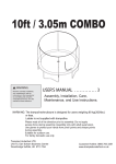
Connections and Setup
For station control & command, connect your
palmtop to port A (COMPUTER)
Rear Panel
Power cable to
Battery
6.50-m coaxial
cable to UHF
antenna
3-2
10-m coaxial cable
to GPS antenna
DSNP
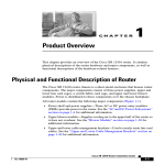
Operating Instructions at the base station
Connections and Setup
Base station
Complete setup,
not shown in real
conditions of
operation
GPS antenna
3
UHF antenna
Battery
Standard tripod,
not provided
Station Unit (GPS receiver
and plug-in UHF transmitter)
secured on stand
DSNP
3-3
3
Operating Instructions at the base station
Measuring the GPS antenna height
Measuring the GPS antenna height
When programming the station, you will need to know the height of
the GPS antenna phase center above the landmark. There are two
ways of measuring this height:
DSNP measurement
With this method, use the Meter Kit Part No. 26I2076601 as
described below. The meter kit is composed of a tape measure and
a measuring arm.
-
Insert the measuring arm into the mast, just under the
antenna base plane.
Insert the tape hook into the measuring arm (upper point)
-
Unwind the tape and place the tip onto the landmark (lower
point)
-
Write down the value read on the scale. This value will be
entered later as the antenna height, with the DSNP
measure option selected (see page 3-8, Measuring the
GPS antenna height).
Insert this end
into the mast
(for transportation, use
this recess to secure the
arm on the tape)
Measuring arm
Insert the tape hook into this slot
Tape measure
Tip
3-4
DSNP
Operating Instructions at the base station
Measuring the GPS antenna height
-
DSNP measurement:
Upper point
Vertical
Tape oblique
3
Lower point
USER measurement
Knowing the location of the phase center in the GPS antenna, you
can measure its height above the landmark with your own method:
If you find it easier, you can split the height measurement into two
distinct vertical components which you measure one after the other.
DSNP
3-5
3
Operating Instructions at the base station
Measuring the GPS antenna height
For example, you can measure the height of the phase center above
an arbitrary mark on the mast (1st measurement) and then measure
the height of this mark above the land mark (2nd measurement).
You just need to use the tape measure for this kind of measurement.
USER measurement illustration (example)
(Tape vertical )
Upper point
Phase center
12 mm
24 mm
0.12 m
Lower point
If, as opposed to the illustration above, the tape hook is placed on
the upper point and the tape tip on the landmark, do not forget to
add 0.12 m to the value you read on the scale.
3-6
DSNP
Operating Instructions at the base station
Programming the base station (Quick Procedure)
Programming the base station (Quick
Procedure)
Preamble
-
lf the station does not need to be programmed or reprogrammed (somebody else did it for you), just press the
ON/OFF push-button on the receiver front panel and then
check that the station reaches its operational status by
reading the information reported on the station's status
display (screen No. 0, see Appendix H).
-
If changes have to be made to the programming of the
station, connect the palmtop and run the Palmtop software
as explained hereafter.
3
In this section, it is assumed that the software has been
properly installed (if required refer to Appendix H for
software loading). In addition, a complete reference
documentation for this software, when used at a base
station, is provided in Appendix D.
-
Basically, a station can function in two different operating
modes:
• The Average position mode, in which the station is
requested to provide a position solution of its own
location at the end of a certain time, by continually
averaging its position solutions collected over this
period of time. This operating mode should be run
only if the position of the station is unknown or
insufficiently known. It should be run for some time
and then the averaged position should be used to
program the station in UHF transmission mode.
• The UHF transmission mode, the normal
operating mode for a base station, in which the
useful data is transmitted to users through a data
link operating in the UHF band.
DSNP
3-7
3
Operating Instructions at the base station
Programming the base station (Quick Procedure)
Getting the Palmtop software started
After pressing the ON/OFF push-button on the receiver front panel
and after checking that the station has reached its operational status
(see screen No. 0, Appendix H), do the following:
-
Connect the FS/GS palmtop to port A on receiver rear
panel, using cable part No. 605076501.
-
Switch on the palmtop by depressing the red key (upper
right).
-
After the DOS prompt has appeared, type in "T" (not casesensitive) and press the "Yes" key (↵).
Let the palmtop complete its self-tests, the end of which is
denoted by the test bar graph disappearing from the
palmtop display and the automatic selection of the
Antenna function.
Note that starting the program will automatically switch the
receiver on if you forgot to do that before. However in this
case, the self-tests on the palmtop will be longer.
Programming steps
-
You will not be allowed to change the settings of the base
station if it is currently transmitting or operating in Average
Position mode.
• Entering the GPS antenna height
-
This function is automatically selected on completion of the
self-tests
In other contexts, select
by using ← or → to access
this function. In the function menu which then appears
select Antenna by using the ↓ key and then press ↵.
3-8
DSNP
Operating Instructions at the base station
Programming the base station (Quick Procedure)
-
Press ← until the upper-right field is selected
-
Press → and from the selection menu which then appears,
select User or DSNP depending on the measurement
made (see page 3-4)
-
Move the cursor to the next field and enter your
measurement. If you chose User, you may have to enter
two measurements instead of one with DSNP (see
illustration opposite the entry fields).
-
Press ↵. The resulting true height of the antenna appears
on the right.
-
Press the Esc key to come back to the main menu
• Loading the coordinate system from the PCMCIA
DSNP
-
Insert the PCMCIA prepared for the job into the GNSS
receiver of the base station.
-
From the main menu, select
-
In the function menu which then appears select Load
Geodesy using the ↓ key.
-
Press ↵ to validate this function. The screen then indicates
the names of the jobs contained in the PCMCIA.
-
Choose one and press ↵ again to let the program load the
coordinate system from that job to the base station
(loading is instantaneous).
-
Press the Esc key to come back to the main menu
3
by using ← or →.
3-9
3
Operating Instructions at the base station
Programming the base station (Quick Procedure)
• Entering the station position
-
From the main menu, select
by using ← or →.
In the function menu which then appears select Position
by using the ↓ key.
Press ↵ to validate this function.
In the new screen which then appears, enter the three
coordinates of the station, expressed in the coordinate
system used (indicated in top line). If they are not
accurately known, enter approximate coordinates. You will
then have to select the Average Position mode (see
below). Note that this screen also indicates the current
value of antenna height with respect to ground.
The station position can also be loaded from a PCMCIA. In this case
however you must check that the point loaded from the PCMCIA is
expressed in the same coordinate system as the one currently used
in the base station. After inserting the PCMCIA into the reader, do
the following:
-
-
Select the Position function
Press the F key.
-
Select a file in the list which appears and then press →
-
Select the point you want to use and then press → again.
This loads the coordinates of this point to the receiver as
the position of the station
• If the coords of the station are not accurate enough,
select the Average Position mode and let the station
operate in this mode for a time that you specify:
-
3-10
From the main menu, select
using ← or →.
In the function menu which then appears, select Average
Position using the ↓ key.
DSNP
Operating Instructions at the base station
Programming the base station (Quick Procedure)
-
Press ↵ to validate this function.
-
Press the R key
In the edit box which then appears, type in the period of
time (hh:mm) during which the station should operate in
the Average Position mode.
Choose this time according to the figures given in the table
below.
Operating time in
Average Position
mode
10 min
30 min
1 hour
12 hours
24 hours
-
Resulting uncertainty
on station's
coordinates
50 meters
30 meters
20 meters
5 to 10 meters
< 5 meters
3
Then press ↵. The base station then starts running in the
Average Position mode (status in the upper-left field:
Running)
From this time, the coordinate fields on this screen will be
updated as new solutions are available. At the end of the
planned time (new status: Stop), they will contain the
average coordinates of the station.
DSNP
3-11
3
Operating Instructions at the base station
Programming the base station (Quick Procedure)
After the station has left the Average Position mode, do the
following:
-
Unless already done, from the main menu, select
then select Average Position.
and
-
Press the A key to transfer the averaged position to the
Position function screen. The station is now ready to
operate in UHF transmission mode.
Warning! A wrong reference position for the base station
will not allow the system to operate properly: rover unit
initialisation will be long, or even impossible, and position
solutions will be wrong.
It is therefore advisable to check the corrections computed
by the base station (displayed on Screen No. 7) after
entering its position. The values of corrections should be in
the order of a few tens of meters.
3-12
DSNP
Operating Instructions at the base station
Programming the base station (Quick Procedure)
• Entering the transmitter characteristics, enabling the
station to transmit
-
-
DSNP
From the main menu, select
using ← or →.
In the function menu which then appears, select the
Transmitter function.
From the screen which then appears, enter the following
parameters:
- Station ID number: identification number of the
station. This number is part of the data conveyed
through the UHF link. The rover unit will test this
number before validating the data received
- Carrier frequency: within the band 410-470 MHz,
necessarily a multiple of 12.5 kHz
- Transmission rate (1 to 6 seconds): the interval of
time between any two consecutive transmit
moments (the data update rate naturally results
from this setting)
- Transmission slot (1 to 4): defines the organization
of the data link if several base stations are used
concurrently. If a single base station is used,
choose “1” for this parameter. If several stations
are used (up to 4), assign a different number to
each station
- Data: choose the type of data transmitted by the
base station (LRK, DSNP C P, DSNP C)
Press ↵ again to validate all these parameters
Press the E key to enable the station to transmit (resulting
status word on the screen: ON)
(later, from this screen, you will press the S key to disable
transmission).
3
3-13
3
Operating Instructions at the base station
Programming the base station (Quick Procedure)
• Programming the recording of raw data on PCMCIA,
programming operating sessions
See Appendix D. ♣
3-14
DSNP
Operating Instructions on the Rover Unit
Preparing for a field survey
4. Operating Instructions on the Rover Unit
Preparing for a field survey
Assembling the various parts
1
2
4
3
5
4
After inspecting all the parts provided in the container (see
Unpacking, page 1-1), proceed as shown above:
1. Secure the palmtop on its holder.
2. Insert the pointed end of the telescopic pole into the hole of
the palmtop support.
3. Secure the support somewhere on the telescopic pole so
that the palmtop be at a proper height (i.e. adapted to your
own height).
4. With a thumb, depress the quick release button on the
support and insert the tipped end of the palmtop holder into
the support. Release the button.
DSNP
4-1
4
Operating Instructions on the Rover Unit
Preparing for a field survey
5. Secure the quick release adapter in the lower part of the
GPS antenna.
6
7
9
10
8
11
6. With a thumb, depress the button on the quick release
adapter and insert the top of the pole into the adapter.
Release the button.
7. Give the GPS antenna the desired height by adjusting the
length of the telescopic pole.
8. Insert fresh battery packs into the battery compartment (a
single way possible for battery insertion).
9. Do not forget to lock the battery compartment.
10. Screw the UHF antenna on top of the mast and insert the
mast into the dedicated location on the receiver holder.
11. Make the necessary connections (described in the next
page).
4-2
DSNP
Operating Instructions on the Rover Unit
Preparing for a field survey
Connections
-
Connect the end of the coaxial cable (protruding from the
belt) to the GPS antenna.
-
Connect the end of the serial line cable (protruding from
the belt) to the palmtop.
-
Make sure the palmtop is fitted with the NiCd battery pack.
-
Connect the end of the coaxial cable protruding from the
UHF antenna mast to the DGPS input (on receiver rear
panel).
GPS antenna
0 dB UHF antenna (whip)
DC power source
(from battery compartment)
connected to either POWER
connector
RS232
push-pull
connector
Telescopic
pole
4
Palmtop
Coaxial
push-pull
connector
Receiver Rear Panel
DSNP
4-3
4
Operating Instructions on the Rover Unit
Introduction to Palmtop Software
Getting ready for surveying
-
Insert the PCMCIA containing the job into
the receiver.
-
Switch on the GNSS receiver by
depressing the ON/OFF
push-button.
-
Put the rover unit
assembly on your back
-
Switch on the palmtop by
depressing the red key
(top right).
Operator ready for
field operations:
Introduction to Palmtop Software
Remember you always use this program whether you are
programming a base station or surveying with the rover unit. After
detecting the type of the attached receiver, the program will
configure itself to offer the right interface.
4-4
DSNP
Operating Instructions on the Rover Unit
Introduction to Palmtop Software
Palmtop Display
All screens are divided into two distinct areas as shown
below. The status area is permanently shown.
Current processing
mode
Count of SVs used
UHF reception level
Battery voltage
indicator
Parameter Area
Status Area
Current processing mode:
H : Hold (no position solution)
I : KART or LRK initialisation
G : GPS
E : EDGPS (metric accuracy)
K : KART (centimetric accuracy)
L : LRK (centimetric accuracy)
4
Count of SVs used:
will blink if the count of SVs drops and remains below 4
UHF reception level icon:
: Minimum level required (blinking)
: 1 to 3 dB above minimum level
: 4 to 8 dB above minimum level
: 9 dB or more above minimum level
Battery voltage indicator:
Below configurable threshold
(blinking)
Above threshold
(increment: about 0.1 V)
About 1 V above threshold
Keys and menus
A few keys and menu types need to be known for best use of
the Palmtop Software program.
DSNP
4-5
4
Operating Instructions on the Rover Unit
Introduction to Palmtop Software
• Main menu screen
The main menu shows the 6 groups of functions available in
the form of icons (see below).
1
2
3
4
5
6
Use the vertical- or horizontal-arrow keys (↑, ↓, →, ←) to
select an icon. The selected icon is surrounded by dotted
lines. Then press ↵ to enter the corresponding function.
Alternately, you can directly enter a function by pressing the
corresponding numeral key (see figures 1 to 6 in the screen
example above)
• Function menus
They are displayed after selecting an icon in the main menu
and pressing ↵. Function menu example:
1
2
3
4
-
-
4-6
Using the vertical-arrow keys, select a function in the menu
and then press ↵ again to run this function
Alternately, you can directly run a function by pressing the
corresponding numeral key (se figures in the screen
example above).
You can directly go from the Function menu of an icon to
that of the next or previous one by pressing → or ←.
DSNP
Operating Instructions on the Rover Unit
Introduction to Palmtop Software
• Help menus
There is a Help menu specific to almost each function, listing
all the commands available in the context of this function.
To display the Help menu, press the F1 key. This causes the
Help menu to be superimposed on the screen. Then do the
following:
- Press the key-letter to run the desired command.
- or simply press the Esc key if you do not want to run any
command. Incidentally, this will remove the Help menu
from the screen
For example, from the Help menu below, pressing the “D” key
will directly display the screen allowing you to set the date.
NOTE: You cannot view any Help menu while editing a
4
parameter.
• Other important keys
Esc
-
Pressing the Esc key will take you back to the preceding
screen, or will remove the Help menu from the screen, or
will cancel the change you make to a parameter. Repeated
presses on this key will take you back to the main menu
F2
-
DSNP
From anywhere in the program, pressing the F2 key will
allow you to display the last solution computed for your
current position (see screen example in page 4-74).
4-7
4
Operating Instructions on the Rover Unit
Introduction to Palmtop Software
Shift+F1
- From anywhere in the program, pressing Shift+F1 will
allow you to access the palmtop’s notepad (see page 483).
F4
- Pressing the F4 key will allow you to quit the program.
Confirm this choice by pressing ↵ (or press Del to cancel
the request). Then a message is displayed asking you
whether, in the same time, the receiver should be turned
off (press the Del key) or not (press ↵).
• Making changes to parameters
Depending on the size and type of the parameters that can be
changed, the program will use different scenarios to let you
make that change:
-
If the screen contains numerical or alpha-numerical parameters,
a cursor (inverse video) will appear on the first of them.
To change this parameter, simply type in the new value. Note
that the position of the field on the screen will be shifted to the
left while you edit it. If the size of the parameter is relatively long,
an edit box will appear on top of the screen to show the entire
field while you edit it.
In both cases, the new value will be validated after you press ↵.
Use ↓ or ↑ to access the next or previous field (respectively).
-
4-8
If a parameter can only be set to some specific software-set
values, then this field will be marked with a “ ”. To know the
possible values and choose one of them, use ↓ or ↑ to access
this field and then press →. A select box appears showing these
values. Use ↓ or ↑ to choose the desired value and press ↵ to
validate your choice (the select box is removed from the screen
at the same time). Alternately, you can directly type the numeral
key corresponding to the row in which the desired value is shown
(same as function menus, see page 4-6).
DSNP
Operating Instructions on the Rover Unit
Getting started
• Messages and alarms
•
•
•
•
•
The buzzer will beep in the following cases:
- At the end of every auto-test
- in case of LRK or KART re-initialisation
- In case of invalid data entry or display request or other errors
Low battery alarm:
- A beep will be heard and the "Battery is low" message will
appear
- Battery icon in the status area will blink until you change the
battery
Satellite alarm:
- Satellite icon in the status area will blink until 4 SVs or more
can be received
Low UHF level alarm:
- A beep will be heard when the reserve of UHF reception level
drops below 3 dB
- UHF reception icon in the status area will blink until reception
conditions come back to normal
Communications problem with receiver:
- A beep will be heard and the "Receiver not responding"
message will appear
4
Getting started
Assuming the rover unit is now ready and you have the palmtop in
hand, do the following:
-
From the DOS prompt, type in "T" or “t” and press ↵. The
following screen appears denoting auto-tests in progress:
...
DSNP
4-9
4
Operating Instructions on the Rover Unit
Getting started
4-10
-
At the end of the auto-tests, the Choose a job screen will
appear asking you to specify the job you want to perform.
-
Then the Choose a file screen will appear asking you to
choose the file in which you want to record your survey
(see next page for more information about these choices).
Then the main menu will appear from which you can run
any function you like. The diagram below reviews all the
possible functions accessible from the 6 icons of the main
menu.
-
Use the vertical- or horizontal-arrow keys (↑, ↓, →, ←) to
select an icon. The selected icon is surrounded by dotted
lines.
-
Press ↵ to validate your selection (or press the
corresponding numeral shortcut key).
DSNP
Operating Instructions on the Rover Unit
Getting started
About jobs and files
All instructions for
executing a job are
contained in a job file:
All the information concerning the
points surveyed for a job is
contained in a results file:
03120900
03121100
03121400
03121600
03121700
*.JOB
You can create up to 5 files
to complete a job.
These files are not files in
the computer sense, but will
appear as headers in the
results file. Default name:
mmddhhmm (month day
hours minutes).
*.RES
Data produced during the
survey through each of these
files is written to the same
results file. Later, using
KISS, you can retrieve just
the necessary data by
invoking the name of the
corresponding file.
Choosing a job
When starting the rover unit, the screen corresponding to this
function is automatically displayed at the end of the auto-tests.
4
Cursor
Choose "none" job name if
you do not have any job to
perform but you only want
to access the main menu
(for maintenance purposes
for example)
Job name
Total number of points in the job
After completing a job, from the main menu, select
select Choose a job (1) to come back to this screen.
DSNP
and then
4-11
4
Operating Instructions on the Rover Unit
Getting started
Associated Help menu:
(Displayed by pressing F1, removed by pressing Esc)
According to context:
-
Press the Yes key (↵) to choose the job you marked with
the cursor in the list of available jobs
-
Or press the V key to view the properties of the marked
job. The properties of a job are:
-
Date when job was created with KISS ((dd/mm/yy
hh:mm:ss)
Operator name
Area name
Comment
Height of mobile GPS Antenna
Job properties example, as viewed on screen:
-
4-12
Or press the C key to create a new job directly in the field,
without having to go back to the office and to resort to
KISS. The screen which then appears allows you to define
the properties of that job (see next page).
DSNP
Operating Instructions on the Rover Unit
Getting started
-
Enter the following parameters:
-
Job name (12 characters max.; current time & date are
prompted by default in the format “mmddhhmm”)
Operator’s name (your name)
Name of the working area (optional)
Any useful comment or note for the job (optional)
Height of the GPS antenna above the ground.
Apart from the Name field, the default properties prompted
for the new job are those of the previously chosen job (this
applies to the Date field as well). On the other hand, the
coordinate system assigned to the new job will necessarily
be the one currently used in the receiver (without any
possibility to change it).
4
The Date field can only be completed by software. When
you create a new job, this field contains the creation date &
time of the previously chosen job. Later on, when you view
the properties of the job being created, then this field will
contain the creation date & time of the job you are creating.
-
Press the F1 key to display the Help menu and select
Store by pressing F3: this causes the new job to be
created (you can also press F3 directly):
The palmtop then comes back to the Choose a job screen
on which you can see the name of the job you have just
created.
DSNP
4-13
4
Operating Instructions on the Rover Unit
Getting started
Choosing a file
When starting the rover unit, the screen corresponding to this
function is automatically displayed at the end of the auto-tests after
you have chosen a job.
Cursor
File name
After completing a job, from the main menu, select
select Choose a file (2) to come back to this screen.
and then
Associated Help menu:
(Displayed by pressing F1, removed by pressing Esc)
According to context:
- Press the Yes key to choose the file you marked with the
cursor in the list of available files. The screen then comes
back to the main menu.
- Or press the C key to create a new file. A new screen
appears allowing you to create this file (up to 5 files max.
can be created for a job).
4-14
DSNP
Operating Instructions on the Rover Unit
Getting started
Apart from the Date field, which contains the current date
& time (dd/mm/yy hh:mm:ss), all parameters on this screen
can be changed. The default name assigned to the file is
the current date & time (format: mmddhhmm). Press ↵
when you agree with the definition of the file.
-
Or press the V key to view the properties of the file (same
type of screen as the previous one).
Checking operating conditions before starting a
survey
-
4
Read the indications provided in the status area of the
palmtop display (see also page 4-5).
Unless the L (or K) processing mode is now displayed in
this area, wait for this letter to appear before proceeding
with your work. When displayed, this letter denotes
successful LRK (or KART) initialisation and the ability for
the rover unit to perform a job. Proper initialisation is
necessarily achieved with at least 4 satellites received and
used
DSNP
-
Check the battery indicator. With fresh batteries, the icon
shape should be as follows:
-
Check the UHF reception level. The higher the reception
level the better.
4-15
4
Operating Instructions on the Rover Unit
Surveying target points (Staking Out)
Surveying target points (Staking Out)
General case
1. Choose a job and a file (as explained in pages 4-11 and
4-14).
and then Stake Out
2. From the main menu, select
(1). The screen now shows the list of target points to be
surveyed for the job
Points were previously surveyed in LRK
Number of points
still to survey
Current job's name
Current distance to marked point
Cursor
Point names
listed here
4-16
Geocode (the one you chose to display)
DSNP
Operating Instructions on the Rover Unit
Surveying target points (Staking Out)
Associated Help menu (3 screens):
(Displayed by pressing F1, removed by pressing Esc. Press PgUp or PgDn to
change help menu)
Guidance: see page 4-19
Stake out with offset: see page 4-26
Search: Press the S key to search for a new
point (to be continued in page 4-64)
View: Press the V key to view the definition
of the selected point (see the 2 screens in
the next page)
Create a point: Press the C key to create a
new point (to be continued in page 4-64)
Create a line: Press the L key to create a
new line (to be continued in page 4-66)
Distance: Press the D key to access the
screen allowing you to measure the distance
between any two points (see page 4-61)
Next point: Press the N key to select the
point you defined as the "next point" (see
below)
Configure next point: Press the P key to
define the nature of the next point (to be
continued in page 4-63)
Geocode display: Allows you to choose
which geocode (1, 2, 3 or 4) should be
displayed in the list of points
View 2D: Projects the locations of the points
onto a plane (see page 4-61). This view
accurately shows the distribution of the
points in the two-dimensional (XY) space.
DSNP
4
4-17
4
Operating Instructions on the Rover Unit
Surveying target points (Staking Out)
Viewing the definition of the selected target point (press the V key
then the PgDn key):
Directly from either of these screens, you can view the equivalent
screen for the next, previous, top-of-list or end-of-list point by
respectively pressing ↑, ↓, Home or End.
4-18
DSNP
Operating Instructions on the Rover Unit
Surveying target points (Staking Out)
3. Using the vertical-arrow keys, PgUp / PgDn or
Home/End, move the cursor to a target point you want
to go to and press ↵. A new screen appears providing
visual instructions to help you walk to this point.
Direction defined
by the target and
your position when
you selected the
target
First North,
then, after your
first steps
toward the
target, average
direction of walk
Name of the
point being
surveyed (the
target)
Distance
to target
Target
Across-line
distance, sign
deduced from
orientation of X axis
Your current position
-
DSNP
Height deviation
between you and
the target
4
Along-line
distance,
+ if you
pass the
point
The leftmost chart will trace your walk to the target, starting
from the position where you were (start position) when you
selected that point. On this chart:
-
the target point is represented by a
throughout the procedure)
-
Your position is represented by a
(immobile
4-19
4
Operating Instructions on the Rover Unit
Surveying target points (Staking Out)
-
The vertical axis represents the direction defined by the
target and your position when you selected the target (start
position).
-
The path you follow as you
walk toward the target is
represented by a dotted line
starting from the start position:
-
The other chart provides visual
information about the direction
to follow to reach the target.
First the vertical axis
represents the North direction.
After you walk a few steps in
the direction of the target, the
vertical axis will then represent
the average direction of walk:
The same symbols as in the left-hand chart are used to
represent the target and your current position. The
distance between the two symbols is not representative of
the true distance.
4. Correct the direction of walk according to the
indications on the screen; walk while continuing to read
the screen for auto-correction of the path followed.
4-20
DSNP
Operating Instructions on the Rover Unit
Surveying target points (Staking Out)
If you realize that you cannot reach the target point, then
press the Esc key to go back to the target points list
screen and then press the O key. Then refer to page 4-26,
Surveying target points through offset procedure.
-
When the distance to the target becomes less than 5 m, a
new chart appears on the screen giving a magnified view
of the area around the target point (± 5 m along each axis).
North
or direction defined by the target and your
position when this chart appears
(user-configurable, see page 4-23)
Target
Solution used for guidance (A for Accurate or R for
Real-time) (user-configurable; see page 4-23)
-
4
When the distance to the target becomes less than 50 cm,
the view is magnified a second time around the target point
(± 0.5 m along each axis).
North
or direction defined by the target and your
position when the previous chart appeared
(±
± 5 m) (user-configurable, see page 4-23)
Target
Solution used for guidance (A for Accurate or R for
Real-time) (user-configurable; see page 4-23)
DSNP
4-21
4
Operating Instructions on the Rover Unit
Surveying target points (Staking Out)
5. Before surveying the point, you can refine the GPS
antenna position so that the “X” accurately coincides
with the origin of the axis system, taking care to
maintain the antenna mast in vertical position. As a
result, the three components in the upper-right frame
should be as close as possible to 0.000. The OK message
will appear, suggesting that the point be recorded now,
when the deviation between the target and your position is
less than the acceptance circle defined for the job (see
page 4-89).
You can still zoom in around the target by pressing the
PgDn key (± 0.15 m along each axis).
4-22
DSNP
Operating Instructions on the Rover Unit
Surveying target points (Staking Out)
Associated Help menu during the guidance phase (2 screens):
(Displayed by pressing F1, removed by pressing Esc. Press PgUp or
PgDn to change help menu)
Invert Axes: (On
guidance chart)
North: Changes
definition of vertical axis
on ± 5 m, ± 0.5 m and ±
0.15 m charts
Stake Out: see next
page.
Initialize Guidance:
Deletes trace on lefthand chart
Zoom Out / Zoom In: Allows you to perform zoomin/zoom-out operations on the guidance chart. Zooming-in
is automatic from the initial view down to 0.50-m scale
(intermediate scale: 5 m) as you approach the target.
Switching to 0.15 m scale can only be manual by pressing
the PgDn key. On the contrary, zooming-out is only
obtained by pressing the PgUp key.
4
Accurate point: Chooses this solution to be used for
guidance (accurate point computed every second)
Real time point: Chooses this solution to be used for
guidance (solution available every 0.5 seconds, slightly
noisier than the accurate point).
NOTE: The "Accurate" solution is always the only position
solution logged, whatever the point you choose for
guidance (Accurate or real-time)
DSNP
4-23
4
Operating Instructions on the Rover Unit
Surveying target points (Staking Out)
6. Press the Yes key to access the log screen. The following
parameters can be changed if required:
- Geocodes 1 & 2 (directly type a geocode in each
field or choose a pre-defined one after pressing →)
- Averaging time in seconds (Average). All the
solutions acquired during this time will be averaged
and only the solution resulting from this
computation will be logged (enter "0" if you just
wish to log the 1st position solution available)
- GPS antenna height above ground
- Comment
Then after pressing PgDn
-
Geocodes 3 & 4 (directly type a geocode in each
field or choose a pre-defined one after pressing →)
Uncertainty on position (see page 4-89)
4-24
DSNP
Operating Instructions on the Rover Unit
Surveying target points (Staking Out)
Associated Help menu:
(Displayed by pressing F1, removed
by pressing Esc).
Logging: see 7 below
Uncertainty Display: see
page 4-89
7. While still maintaining the GPS antenna mast in
position, press the F3 key. Stay immobile until the buzzer
bleeps (waiting time depends on chosen averaging time).
The following is displayed during this time (example):
The end of recording is denoted by the display of the target
points list on the screen. Note that the point you have just
surveyed is now marked with a letter corresponding to the
processing mode used (“L” for “LRK”, etc.).
4
The next target point (see definition in page 4-63) in the list
is pre-selected to be the next point to be surveyed.
DSNP
4-25
4
Operating Instructions on the Rover Unit
Surveying target points (Staking Out)
Surveying target points through offset procedure
If you know, or if you realize in the course of your walk to a target,
that you cannot reach this target with the rover unit —because for
example the reception conditions at this point could not allow the
system to operate normally — then use one of the following two
methods to survey this target: linear offset or lateral offset.
• Linear Offset Principle
Through this technique, the location of the inaccessible target point
(P) will accurately be deduced from two points (P1 and P2) located
nearby, properly logged, and both aligned with the target.
First, the operator will freely choose and log the first point (P1), thus
allowing the rover unit to define the direction of a line to P.
Then the rover unit will guide the operator to the other point (P2) in
order to align this point with the other two. The operator will then log
P2.
As a result, the rover unit will provide the distances separating P1
and P2 from the target.
Finally, by way of external means (a simple meter for example), the
operator will measure one of the distances from P1 and P2 (or the
two) to the target to accurately locate this point.
P
P1-P
P1
P2
4-26
P2-P
DSNP
Operating Instructions on the Rover Unit
Surveying target points (Staking Out)
• Lateral Offset Principle
Through this technique, the location of the inaccessible target (P) will
accurately be deduced from two points (P1 and P2) located nearby,
properly logged, and forming a triangle (ideally an equilateral one)
with P.
First, the operator will freely choose the first point (P1). The operator
will log this point thus allowing the rover unit to provide the distance
separating this point from P.
Then, the operator will freely choose the other point (P2), keeping in
mind that P1 and P2 should form a "regular" triangle with the
presumed location of P. The operator will also log point P2 thus
allowing the rover unit to provide the distance separating this point
from P.
As a result, the rover unit will also indicate the direction of P (to the
right or to the left) in reference to the oriented segment P2P1.
Finally, by way of external means (a simple meter for example), the
operator will measure the distances from P1 and P2 to P, drawing
two arcs of circles on the ground, the intersection of which (to the
right or to the left of P2P1) will provide the exact location of P.
P1-P
P1
P1
P1-P
P,
to the
left
P,
to the
right
P2-P
DSNP
4
P2
P2
P2-P
4-27
4
Operating Instructions on the Rover Unit
Surveying target points (Staking Out)
• Linear Offset Procedure
Assuming you are in the vicinity of the inaccessible target, the
palmtop screen displays the target points list of your job and the
inaccessible target is selected in the list (see this context in page 416), then do the following:
1. Press the O key. In the menu which appears, select the
linear offset type:
A guidance screen then appears prompting you to freely
choose P1 and to log this point:
Flashing dotted
lines around P1
prompt you to
choose this point in
the field and log it
2. Press the Yes key to access the log screen (same log
context as in Staking Out general case; see page 4-24).
3. While maintaining the GPS antenna mast in position,
press the F3 key. Stay immobile until the buzzer bleeps
(waiting time depends on chosen averaging time).
4-28
DSNP
Operating Instructions on the Rover Unit
Surveying target points (Staking Out)
After P1 logging, the following screen appears prompting
you to walk to P2:
P1 survey complete
0.29 m
P
Flashing
dotted lines
around P2
prompt you to
walk to this
point to log it
P1
Your current
location
P2
0.40 m
In this example, move 0.40 m
to the left to join P2
4. Walk to P2, observing the two indications provided in
the left-hand part of the screen. Remember the program
4
just requests that P2 be aligned with P1 and P, which
means that you can freely choose the distance separating
P2 and P1.
Once P2 is aligned with the other points, the guidance
screen will look like this:
DSNP
4-29
4
Operating Instructions on the Rover Unit
Surveying target points (Staking Out)
5. Press the Yes key to access the log screen (same log
context as in Staking Out general case; see page 4-24).
6. While maintaining the GPS antenna mast in position,
press the F3 key. Stay immobile until the buzzer bleeps
(waiting time depends on chosen averaging time).
After P2 logging the following screen appears providing the
distances from P1 and P2 to the inaccessible target (P):
P2 survey complete
7. Using the information now available on the palmtop
screen, locate the inaccessible target with your own
means.
8. Position the cursor on the P icon and, from any
location, press the Yes key to store the P point as a
point surveyed through offset procedure.
• Lateral Offset Procedure
Assuming you are in the vicinity of the inaccessible target, the
palmtop screen displays the points list of your job and the
inaccessible target is selected in the list (see this context in page 416), then do the following:
1. Press the O key. In the menu which appears, select the
lateral offset type:
4-30
DSNP
Operating Instructions on the Rover Unit
Surveying target points (Staking Out)
A guidance screen then appears prompting you to freely
choose P1 and to log this point:
Flashing dotted
lines around P1
prompt you to
choose this point in
the field and log it
2. Press the Yes key to access the log screen (same log
context as in Staking Out general case; see page 4-24).
3. While maintaining the GPS antenna mast in position,
press the F3 key. Stay immobile until the buzzer bleeps
4
(waiting time depends on chosen averaging time).
After P1 logging, the following screen appears prompting
you to walk to P2:
P1 survey complete
P1-to-P distance
Flashing
dotted lines
around P2
prompt you to
walk to this
point to log it
DSNP
4-31
4
Operating Instructions on the Rover Unit
Surveying target points (Staking Out)
4. Choose an adequate location for P2 (i.e. so that the 3
points form a regular triangle).
5. Press the Yes key to access the log screen (same log
context as in Staking Out general case; see page 4-24).
6. While maintaining the GPS antenna mast in position,
press the F3 key. Stay immobile until the buzzer bleeps
(waiting time depends on chosen averaging time).
After P2 logging the following screen appears providing the
distances from P1 and P2 to the inaccessible target (P)
and the direction of the target with respect to the oriented
P2P1 segment:
P1-to-P distance
Direction of
target with
respect to P2P1,
as determined
by the rover unit
P2-to-P distance
7. Using the information now available on the palmtop
screen, locate the inaccessible target with your own
means.
8. Position the cursor on the P icon and, from any
location, press the Yes key to store the P point as a
point surveyed through offset procedure.
4-32
DSNP
Operating Instructions on the Rover Unit
Surveying target points (Staking Out)
• Associated Help menu during offset procedures
The same Help menu is available when surveying a planned point
through either of the available offset procedures:
(Displayed by pressing F1, removed by pressing Esc)
DSNP
-
Press the Yes key to access the log screen when you are
ready to log the position of P1 or P2 or to log P.
-
Press the V key to view the characteristics of the selected
point on the guidance chart
-
Press the S key if you want to enable or disable the
palmtop buzzer (this command is available in linear offset
only)
-
Press the Del key if you want to delete the selected point
(P1 or P2) and resume the logging of this point
-
Press the Clr key if you want to resume the offset
procedure from the beginning (P1 and P2 deleted).
4
4-33
4
Operating Instructions on the Rover Unit
Logging points
Logging points
At any time during a job, you can log the position of any point. In
what follows, it is assumed that a job and a file have been previously
opened (see page 4-11).
General case
and then
1. Come back to the main menu, select
choose Logging (2). The log screen appears.
Uncertainty on position (see page 4-89)
2. Change some of the parameters on this screen if
necessary:
-
-
4-34
Name of logged point (default: point #)
Geocodes 1 & 2 (directly type a geocode in each
field or choose a pre-defined one after pressing →)
Averaging time in seconds (Average). All the
solutions acquired during this time will be averaged
and only the solution resulting from this
computation will be logged (enter "0" if you just
wish to log the 1st position solution available)
GPS antenna height above ground
Comment
DSNP
Operating Instructions on the Rover Unit
Logging points
After pressing PgDn, you can also change Geocodes 3 &
4 (directly type a geocode in each field or choose a predefined one after pressing →).
Name you have just defined for
the logged point
Associated Help menu:
(Displayed by pressing F1, removed
by pressing Esc).
4
Logging: see 3 below
Uncertainty Display: see
page 4-89
3. While maintaining the GPS antenna mast in position,
press the F3 key. Stay immobile until the buzzer bleeps
(waiting time depends on chosen averaging time). The
following is displayed during this time (example):
The end of recording is denoted by the display of the
default characteristics for the next point to be logged.
DSNP
4-35
4
Operating Instructions on the Rover Unit
Logging points
Logging points through offset procedure
For the same reasons as in staking out (see page 4-26), you may
have to resort to an offset procedure to log the position of an
inaccessible point. Three different methods exist in this case to log a
non-planned point: linear, lateral and intersection.
• Linear Offset Principle
Through this technique, the location of the inaccessible point (P) will
accurately be deduced from two points (P1 and P2) located nearby,
properly logged, and both aligned with the point.
First, the operator will freely choose two points in the field (P1 and
P2) aligned with point P.
After measuring —with other means— one of the distances
separating P1 or P2 from P, the operator will enter this distance in
the corresponding field, from which the rover unit will deduce the
position of P.
P
P1
P1-P
P2-P1
P2
• Lateral Offset Principle
Through this technique, the location of the inaccessible point (P) will
accurately be deduced from two points (P1 and P2) located nearby,
properly logged, and forming a triangle (ideally an equilateral one)
with P.
First, the operator will freely choose two points in the field (P1 and
P2) forming a "regular" triangle with P.
4-36
DSNP
Operating Instructions on the Rover Unit
Logging points
After measuring —with other means— the distances separating P1
and P2 from P, the operator will enter successively each of these
distances when logging these points. The direction of P with respect
to the oriented segment P2P1 will also have to be specified.
P1
P1
P1-P
P1-P
P,
to the
left
P,
to the
right
P2-P
P2
P2
P2-P
• Intersection offset principle
Through this technique, the location of the inaccessible point (P) will
accurately be deduced from two pairs of points (P1,P2) and (P3,P4)
defining two lines intersecting at point P.
First, the operator will freely choose the two pairs of points in the
field so that the engendered lines intersect at P .
4
Then the operator will successively log the 4 points P1, P2, P3 and
P4. The interest of this method lies on the fact that the operator does
not need to measure anything in the field, apart from making sure
that first, P1 and P2 are aligned with P, and second, that P3 and P4
are also aligned with P.
P1
P
P3
P4
P2
DSNP
4-37
4
Operating Instructions on the Rover Unit
Logging points
• Linear Offset Procedure
In what follows, it is assumed that a job and a file have been
previously opened (see page 4-11). After marking P1 and P2 in the
field and after measuring the P1-to-P distance for example, do the
following:
1. Come back to the main menu, select
, choose
Logging with offset (5) and then select Linear:
2. Walk to P1 and stay immobile at this point
3. Press the Yes key to access the log screen (same log
context as in Logging general case; see page 4-34).
4. While maintaining the GPS antenna mast in position, press
the F3 key. Stay immobile until the buzzer bleeps (waiting
time depends on chosen averaging time).
5. After P1 logging, select the P1P distance field (upper right) and enter this distance (e.g. 15.25 m). The screen
now looks like this:
Can only be
completed by the
system
4-38
DSNP
Operating Instructions on the Rover Unit
Logging points
6. Walk to P2. Choose it to be aligned with P1 and P. Stay
immobile at this point.
7. Press the Yes key to access the log screen (same log
context as in Logging general case; see page 4-34).
8. While maintaining the GPS antenna mast in position, press
the F3 key. Stay immobile until the buzzer bleeps (waiting
time depends on chosen averaging time).
After P2 logging, the rover unit computes the other
distances represented on the screen. For example, at the
end of the procedure, your screen looks like this:
4
9. Position the cursor on the P icon and, from any
location, press the Yes key to store the P point as a
point surveyed through offset procedure.
• Lateral Offset Procedure
In what follows, it is assumed that a job and a file have been
previously opened (see page 4-11). After marking P1 and P2 in the
field and after measuring the two distances to P, do the following:
1. Come back to the main menu, select
, choose
Logging with offset (6) and then select Lateral:
DSNP
4-39
4
Operating Instructions on the Rover Unit
Logging points
2. Walk to P1 and stay immobile at this point
3. Press the Yes key to access the log screen (same log
context as in Logging general case; see page 4-34).
4. While maintaining the GPS antenna mast in position, press
the F3 key. Stay immobile until the buzzer bleeps (waiting
time depends on chosen averaging time).
5. After P1 logging, select the P1P distance field (upper-right)
and enter this distance (e.g. 25.00 m). The screen should
now look like this:
6. Walk to P2 and stay immobile at this point
7. Press the Yes key to access the log screen (same log
context as in Logging general case; see page 4-34).
8. While maintaining the GPS antenna mast in position, press
the F3 key. Stay immobile until the buzzer bleeps (waiting
time depends on chosen averaging time).
9. After P2 logging, select the P2P distance field (lower-right)
and enter this distance (e.g. 65.00 m).
4-40
DSNP
Operating Instructions on the Rover Unit
Logging points
10. Specify the location of P with respect to the oriented
segment P2P1. Once the cursor is located at the right
point, press the Yes key to confirm this location and store
this point as a point surveyed through offset procedure.
The screen should now look like this:
Point to the right
of P2P1
NOTE: You can use P1 and P2 as many times as
4
necessary to log other inaccessible points (in the vicinity of
P1 and P2).
• Intersection Offset Procedure
In what follows, it is assumed that a job and a file have been
previously opened (see page 4-11). After marking P1 to P4 in the
field, do the following:
1. Come back to the main menu, select
, choose
Logging with offset (6) and then select Intersection:
2. Walk to P1 and stay immobile at this point
3. Press the Yes key to access the log screen (same log
context as in Logging general case; see page 4-34).
DSNP
4-41
4
Operating Instructions on the Rover Unit
Logging points
4. While maintaining the GPS antenna mast in position, press
the F3 key. Stay immobile until the buzzer bleeps (waiting
time depends on chosen averaging time).
5. Repeat step 2 to step 4 successively for points P2, P3 and
P4
Once all the points have been successfully logged, the
screen should look like this:
6. Position the cursor on the P icon and, from any location,
press the Yes key to store P as a point surveyed through
offset procedure.
• Associated Help menu during offset procedures
The same Help menu is available when surveying a non-planned
point through either of the available offset procedures:
(Displayed by pressing F1, removed by pressing Esc)
Press the Yes key to access the log screen
when you are ready to log the position of
P1, P2, P3, P4 or P
- Press the V key to view the characteristics
of the selected point on the guidance chart
Press the Del key if you want to delete the selected point
(P1, P2 P3 or P4) and resume the logging of this point
Press the Clr key if you want to resume the offset
procedure from the beginning (all points deleted)
-
-
4-42
DSNP
Operating Instructions on the Rover Unit
Surveying a trajectory
Surveying a trajectory
There are two ways of surveying a trajectory:
-
Surveying in Distance mode: as you walk along the
trajectory, the rover unit logs your current position every x
meters traveled until you stop working in this mode.
-
Surveying in Time mode: as you walk along the trajectory,
the rover unit logs your current position every x seconds
until you stop working in this mode.
In both cases and at any time during the survey of the trajectory, you
are allowed to perform the logging of a point. This point will also be
part of the series of points making up the trajectory.
Because the two procedures are very similar, we will only describe
one of them (distance mode) and we will annotate the parameters
which are different when the other mode is used.
1. Come back to the main menu, select
and choose
Trajecto (4). The following dialog box appears:
4
2. Choose the Distance mode. The screen should then look
like this:
Or Time, in seconds, if surveying in Time
mode has been selected
DSNP
4-43
4
Operating Instructions on the Rover Unit
Surveying a trajectory
3. Change some of the parameters on this screen if
necessary:
-
-
Name of start point
Geocodes 1 & 2
Distance: value of distance, in meters, causing a
new point to be logged whenever this distance has
been traveled by the field operator
or, in Time mode:
Time: value of time, in seconds, causing a new
point to be logged whenever this time has elapsed
GPS antenna height above ground
Comment
After pressing PgDn, you can also change Geocodes 3 &
4.
Associated Help menu before starting surveying the trajectory:
(Displayed by pressing F1, removed by
pressing Esc)
-
Start: see below
Uncertainty display: see page 4-
89
4-44
DSNP
Operating Instructions on the Rover Unit
Surveying a trajectory
4. Press the F3 key to start surveying the trajectory. The
screen should now look like this:
Total number of
points recorded since
beginning of
trajectory surveying
Total time (mm:ss)
elapsed since
beginning of
trajectory surveying
(includes time of
pause, if any)
Distance traveled since beginning of
trajectory surveying (does not include
distance traveled during pause, if any)
Current sound setting
recalled here
Associated Help menu while surveying a trajectory:
(Displayed by pressing F1, removed by pressing Esc)
DSNP
-
Press the S key to definitively stop the trajectory surveying
-
Press the P key to suspend the surveying of the trajectory
-
After pressing the P key for a pause, press the R key to
continue the surveying of the trajectory
-
Press the F3 key to log an additional point. This point will
be part of the trajectory. When selecting this function,
proceed as explained in page 4-34 or 4-36.
-
Press the B key to toggle the sound setting (on or off)
4
4-45
4
Operating Instructions on the Rover Unit
Surveying reference points
Screen obtained with trajectory surveying paused (in
distance mode):
Surveying reference points
Assuming a job and a file are open:
-
and then Reference
From the main menu, select
point (3). The screen shows the list of reference points
prepared for the selected job.
-
Select a reference point and then proceed as if it were a
target point (refer to this procedure described from page 416).
NOTE: If your intention is to survey reference points to
determine or refine the coordinate system used, this
procedure should be run from a different context (please
refer to page 4-51).
4-46
DSNP
Operating Instructions on the Rover Unit
Guidance along a profile
Guidance along a profile
This function provides the operator with guidance instructions to help
him/her walk along a profile. In fact, a profile is a series of points
which the operator has previously chosen and placed in a given
order. The straight line connecting any two consecutive points that
are part of the profile is called segment.
From the screen providing guidance, the following operations can be
performed:
- Logging any point
- Logging a trajectory in distance or time mode
- Manual selection of the next or previous segment.
NOTE: You cannot create a profile with KISS. Instead, you
can anticipate the creation of a profile by creating the
corresponding points with appropriate names (i.e. producing
the list of points in the desired order when sorting these
points into alphabetical order) and by allocating the same
geocode to all these points. Then, on the palmtop, you will be
able to quickly retrieve these points through the search
command —by specifying the appropriate geocode
criterion— so that you can use the resulting list of points
directly as a profile.
4
Assuming a job and a file are open:
1. From the main menu, select
then Profile (6). If no
profile has been defined yet for the job, then the screen
shows an empty list:
DSNP
4-47
4
Operating Instructions on the Rover Unit
Guidance along a profile
Associated Help menu (3 screens):
(Displayed by pressing F1, removed by pressing Esc. Press PgUp or PgDn to
change help menu)
Guidance: see page 4-50
Insert a point: See next page
Insert points: See next page
Delete a point: Press the Del key to
remove the selected point from the
profile
Delete all points: Press the Clr to
remove all the points currently making
up the profile
Search: Press the S key to search for
a new point (to be continued in page
4-64)
View: Press the V key to view the
definition of the selected point
Next point: Press the N key to select
the point you defined as the "next
point" (see below)
Configure next point: Press the P
key to define the nature of the next
point (to be continued in page 4-63)
Geocode display: Allows you to
choose which geocode (1, 2, 3 or 4)
should be displayed in the list of
points
View 2D: Projects the locations of the
points onto a plane (see page 4-69).
This view accurately shows the
distribution of the points in the twodimensional (XY) space.
4-48
DSNP
Operating Instructions on the Rover Unit
Guidance along a profile
2. Press the F key (or the I key for a point-by-point selection)
to create the list of points forming the profile. The following
dialog box displays:
3. After making a selection, press the Yes key. If you pressed
the F key, another dialog box appears asking you to
specify the type of selection you want to do:
All: you want to select all the points from the selected list
4
P1...P2: you want to select all the points between two
points which you have then to specify (these two points will
also be part of the selection)
By name: you want to select all points whose names
include a string that you must specify (use * if necessary)
By geocode: you want to select all points whose geocodes
include a string that you must specify (use the wild card
symbol “*” if necessary).
DSNP
4-49
4
Operating Instructions on the Rover Unit
Guidance along a profile
4. Once the profile has been defined, press the Yes key to let
the system compute and display guidance instructions
helping you walk along each segment of the profile.
Example of screen then obtained:
Direction defined
by the orientation
of the segment you
are following
North
Segment’s arrival point
(CERCLE PT 11) Cross track error;
“−” sign if you are
on the left of the
segment
Your current
position
Distance to
arrival point,
projected onto
segment
Segment
Segment’s start point
(CERCLE PT 9)
Distance to
start point,
projected onto
segment
Associated Help menu:
(Displayed by pressing F1, removed by pressing Esc)
Logging: see page 4-34
Trajecto (distance): See page 4-43
Trajecto (time): See page 4-43
Next profile: Press the Up key to
display the next segment (on leftmost
diagram)
Previous profile: Press the Down key
to display the previous segment (on
leftmost diagram)
Initialize guidance: Press the Clr key
to delete the trace of the path you have
followed since the previous initialization
(on leftmost diagram).
5. Now that guidance instructions are provided on the screen,
proceed with the job as such.
4-50
DSNP
Operating Instructions on the Rover Unit
Refining the coordinate system by surveying reference points
Refining the coordinate system by
surveying reference points
When the work area includes reference points whose locations are
accurately known in the coordinate system you have to use, and on
the other hand some of the characteristics of this coordinate system
are not precisely known, then you can rely on the surveying of these
points to refine the definition of the coordinate system.
This kind of computation can be performed either by the rover unit
or, when back at the office, by the KISS module of 3SPack. Refer to
the 3SPack Reference Manual or to the On-Line Help file of the
KISS module for more information about geodetic choice issues.
When surveying a point, basically the rover unit computes the
coordinates of this point on the WGS84. Then computations are run
to transform these WGS84 coordinates into coordinates expressed
on the chosen datum and projection.
If we assume that both the "theoretical" coordinates of a reference
point expressed in the partially unknown system and the surveyed
WGS84 coordinates for the same point are error-free, then the rover
unit can refine the coordinate system used so that the "theoretical"
coordinates of the point be precisely the coordinates obtained by
transforming the surveyed WGS84 coordinates using the refined
coordinate system.
4
Two kinds of computation can be performed in the rover unit:
- refining the horizontal system (local grid)
- or/and refining the vertical system (height correction)
When preparing a job with KISS, if reference points are created for
the purpose of refining the coordinate system used, then follow the
instructions below to refine the coordinate system.
Note that a third type of computation is possible using reference
points surveyed by the rover unit. The purpose of this computation,
which can only be performed with KISS when back at the office, is to
refine the datum shifts of the system used (if it is a standard one).
DSNP
4-51
4
Operating Instructions on the Rover Unit
Refining the coordinate system by surveying reference points
Refining the horizontal system (local grid)
• Phase 1: surveying the known reference points
1. From the main menu, select
and then Local grid (4). On the
screen which then appears,
position the pointer on the Grid
field:
2. Press → to access the Local Grid
screen.
Unless already done, select No in
this field (compulsory):
Help menu associated with this screen:
3. Press the C key (Compute). The
screen now shows a list of
"blank" reference points (see
opposite). You have first to
transfer "true" reference points to
this list. For example if 3
reference points have been created in the job for the
purpose of refining the coordinate system, you should now
transfer these 3 points to the above list (to appear as the
first 3 points in the list for
example).
Associated Help menu:
4-52
DSNP
Operating Instructions on the Rover Unit
Refining the coordinate system by surveying reference points
4. In the list, select Point 1 and then press the F key (Get a
point from file). The list of reference points defined for the
job now appears on the screen
5. Select one of the reference points you wish to use to refine
the coordinate system and then press the Yes key.
6. Repeat steps 4 and 5 until all the useful
reference points are transferred. The
screen now should look like this:
7. Select the first reference point in the list
(ref 1), walk to this point and when arrived at this point, log
its position by pressing the F3 key (same procedure as if
you were logging a point; see page 4-34). After logging this
point, the palmtop comes back to the list of reference
points.
NOTES: The point name is now preceded by a letter
indicating the valid processing mode when the point was
logged (example: "L").
4
In this particular context, there cannot be any guidance
screen to help you reach the reference point as this would
require a thoroughly defined coordinate system, which is
precisely not the case.
If these reference points have been previously surveyed to
refine the height correction, then you do not need to
resume this operation. In this case, you can skip steps 3 to
8.
8. Repeat step 7 until all the reference
points are logged:
DSNP
4-53
4
Operating Instructions on the Rover Unit
Refining the coordinate system by surveying reference points
9. To involve each of the surveyed
reference points into the local
grid computation, successively
select each of them and press
the U key (see associated Help
menu). Finally the screen should
look like this:
• Phase 2: computing the local grid
10. Press the Yes key to start computing the local grid. First,
you must specify whether some parameters of the local
grid should be fixed. Highlight the desired option and press
the Yes key (a single selection possible):
Usual choice: None
If you elect to fix some parameters, then they will be fixed
to their current values.
Then, the program asks you whether you want to fix the
origin of the grid or not:
Usual choice: Not fixed
4-54
-
Not fixed: The barycenter of the selected points
will be used as the origin of the local grid.
-
Fixed: The values of Easting0 and Northing0
coordinates displayed when accessing the Local
Grid screen (see step 2) are chosen to be the
origin of the local grid.
DSNP
Operating Instructions on the Rover Unit
Refining the coordinate system by surveying reference points
At the end of the computation the deviations
between the theoretical locations of the reference
points and the coordinates obtained by projecting
the surveyed WGS84 coordinates onto the
computed local grid are provided opposite the
point names.
The closer to 0.00 these deviations, the better the
computed local grid:
• Phase 3: validating the new local grid
11. Press the Esc key to come back to the screen displaying
4
the characteristics of the grid
12. Position the cursor in the Grid field and select Yes. This
validates the new local grid. Screen example:
End of procedure.
DSNP
4-55
4
Operating Instructions on the Rover Unit
Refining the coordinate system by surveying reference points
Computing the vertical system (height correction)
• Phase 1: surveying the known reference points
1. From the main menu, select
and then Height correction (5).
On the screen which then appears,
position the pointer on the
Correction field:
2. Press → to access the Linear
correction screen.
Unless already done, select No in
this field (compulsory):
Help menu associated with this screen:
3. Press the C key (Compute). The
screen now shows a list of
"blank" reference points (see
opposite). You have first to
transfer "true" reference points to
this list. For example if 3
reference points have been created in the job for the
purpose of refining the coordinate system, you should now
transfer these 3 points to the above list (to appear as the
first 3 points in the list for
example).
Associated Help menu:
4-56
DSNP
Operating Instructions on the Rover Unit
Refining the coordinate system by surveying reference points
4. In the list, select Point 1 and then press the F key (Get a
point from file). The list of reference points defined for the
job now appears on the screen
5. Select one of the reference points you wish to use to refine
the coordinate system and then press the Yes key.
6. Repeat steps 4 and 5 until all the useful
reference points are transferred. The
screen now should look like this:
7. Select the first reference point in the list
(ref 1), walk to this point and when arrived at this point, log
its position by pressing the F3 key (same procedure as if
you were logging a point; see page 4-34). After logging this
point, the palmtop comes back to the list of reference
points.
NOTES: The point name is now preceded by a letter
indicating the valid processing mode when the point was
logged (example: "L").
4
If these reference points have been previously surveyed to
refine the local grid, then you do not need to resume this
operation. In this case, you can skip steps 3 to 8.
8. Repeat step 7 until all the reference
points are logged:
DSNP
4-57
4
Operating Instructions on the Rover Unit
Refining the coordinate system by surveying reference points
9. To involve each of the surveyed
reference points into the height
correction computation,
successively select each of them
and press the U key (see
associated Help menu). Finally
the screen should look like this:
• Phase 2: computing the vertical system
10. Press the Yes key to start computing the height correction.
At the end of the computation, the deviations between the
theoretical heights of the reference points and those
obtained with the computed vertical system are provided
opposite the point names. The closer to 0.00 these
deviations, the better the computed vertical system:
• Phase 3: validating the new vertical system
11. Press the Esc key to come back to the screen displaying
the characteristics of the vertical system.
12. Position the cursor in the Correction field and select Yes.
This validates the new vertical system. Screen example:
End of procedure.
4-58
DSNP
Operating Instructions on the Rover Unit
Ancillary procedures
Ancillary procedures
Working on the results of the job
-
Come back to the main menu, select
and then Result
point (3). A new screen now appears showing the list of
surveyed points. Small icons are used to help you identify
the type of each point surveyed. Screen examples :
Number of points
in the file
Current job's name
Logged
reference point
Logged
target point
4
Logged point
Point names
listed here
Geocode (the one you
chose to display)
Offset procedure:
Inaccessible point:
"P1" point: 1
"P2" point: 2
Trajectory
(start and
end points)
point)
DSNP
4-59
4
Operating Instructions on the Rover Unit
Ancillary procedures
Associated Help menu (2 screens):
(Displayed by pressing F1, removed by pressing Esc. Press PgUp or PgDn to
change help menu)
Guidance: see page 4-19
Search: Press the S key to search for a new
point (to be continued in page 4-64)
View: Press the V key to view the definition of
the selected point (see the 2 screens in the
bottom of this page)
Create a point: Press the C key to create a
new point (to be continued in page 4-64)
Create a line: Press the L key to create a
new line (to be continued in page 4-66)
Distance: Press the D key to access the
screen allowing you to measure the distance
between any two points (see page 4-61)
Next point: Press the N key to select the
point you have defined as the "next point"
(see below)
Configure next point: Press the P key to define the nature of the next
point (to be continued in page 4-63)
Geocode display: Allows you to choose which geocode (1, 2, 3 or 4)
should be displayed in the list of points
View 2D: Projects the locations of the points onto a plane (see page 469). This view accurately shows the distribution of the points in the twodimensional (XY) space.
Viewing the results of the selected point (press the V key then the
PgDn key):
Directly from either of these screens, you can view the equivalent
screen for the next, previous, top-of-list or end-of-list point by
respectively pressing ↑, ↓, Home or End.
4-60
DSNP
Operating Instructions on the Rover Unit
Ancillary procedures
Measuring the distance between any two points
(Continued from page 4-17 or 4-60)
This function allows you to know the distance between any two
points. Once you have selected the two points, the following
parameters are determined:
-
Modulus, horizontal and vertical components of the
distance (and the resulting elevation angle)
-
Azimuth angle of the straight line connecting the selected
two points.
Procedure:
4
1. Before running this function, from the points list, select the
first of the points involved in the measurement (in the
example below, this point is named “CERCLE PT 4”)
2. Then press the D key. The screen which then appears
shows the name of the point you have just selected (P1).
Until the second point is selected, the results displayed on
that screen are those computed for the distance separating
your current position from the selected P1 point.
DSNP
4-61
4
Operating Instructions on the Rover Unit
Ancillary procedures
Help menu associated with the previous screen:
(Displayed by pressing F1, removed by pressing Esc)
3. Press the F key to be able to select the second point (P2).
Specify the type of this point…:
…and then choose it from the list
which then displays (CERCLE PT
nd
10 in the example below). Now that the 2 point is
selected, the results displayed on the screen are those for
the distance separating P2 from P1:
4. If needed, you can write these results into the notepad by
simply pressing the N key. The data transferred to the
notepad, and corresponding to the previous screen, would
be formatted as follows in the notepad:
4-62
DSNP
Operating Instructions on the Rover Unit
Ancillary procedures
Configuring the "next point"
(Continued from page 4-17 or 4-60)
In the context described in either of these pages, the following
screen will be obtained after you press the P key. Then whenever
you press the N key in the same context, the program will
automatically refer to the criterion you specified in the screen below
to select the "next point":
As shown on this screen, you can choose one of the following 4
criteria:
-
Offset (or Line Increment):
4
+1⇒ selects point in next line
−1⇒ selects point in preceding line, etc.
-
Nearest (Yes/No)
-
By name (12 characters max.; you can use one or two "*",
one at the beginning, one at the end; this symbol can
replace one or more characters in a name)
-
By geocode (12 characters max.; you can use one or two
"*", one at the beginning, one at the end; this symbol can
replace one or more characters in a geocode).
You can combine several criteria. You cannot however combine the
Nearest criterion with the Offset criterion.
DSNP
4-63
4
Operating Instructions on the Rover Unit
Ancillary procedures
"Search" function
(Continued from page 4-17 or 4-60)
In the context described in either of these pages, the following
screen will appear after you press the S key.
-
Select the desired option
-
If you select by name or by geocode, a new dialog box
will appear asking you to specify the search criterion
The Search and Next Point functions are much similar (same
purpose, nearly the same criteria). The main difference is that with
the Search function, you will have to specify a criterion every time
you run this function, which is not the case with the Next Point
function. Another difference is that criteria combination is possible
with Next Point, not with Search.
Creating a point
(Continued from page 4-17 or 4-60)
In the context described in either of these pages, the following
screen will appear after you press the C key:
-
4-64
Select the type of point you wish to create and press the
Yes key. The screen which then appears allows you to
enter the characteristics of the new point (default values:
those of the point selected in the list).
DSNP
Operating Instructions on the Rover Unit
Ancillary procedures
-
Make the necessary changes. Example:
-
Then press PgDn and make the necessary changes.
Example:
4
-
When the definition is complete, and as suggested by the
associated Help menu...
... press the F3 key to store the new point.
DSNP
4-65
4
Operating Instructions on the Rover Unit
Ancillary procedures
Creating a line
(Continued from page 4-17 or 4-60)
The notion of line is just used in the rover unit to create a series of
aligned points.
There are two ways of creating a line:
-
either you define the start point, the azimuth of the line and
any 2 of the following 3 parameters:
-
-
number of points in the line
basic distance between any two consecutive points
total length of the line
or you simply define the start point, the end point and the
number of points along the line (or the basic distance
between any two consecutive points). The end point can
be the location of a target point, a reference point or a
result point.
In both cases, the start location of the line is necessarily that
provided by the currently selected point.
In the context described in page 4-17 or 4-60, the following screen
type will appear after you press the L key:
Name of selected
point. This point
provides the
location of the
beginning of the line
-
4-66
On this screen, enter the parameters defining the line. If
you want to define the end of the line with a point, then you
don't need to enter an azimuth angle.
DSNP
Operating Instructions on the Rover Unit
Ancillary procedures
-
Then press the PgDn key. On the new screen which then
appears, enter a name for the start point of the line and the
possible associated geocodes. Screen example:
Preferably choose a name for the start point so that a
numerical string is included at the end of this name (e.g.
tarpt001).
In fact when you store the line (i.e. you let the program
create the aligned target points), automatic point naming is
performed on the basis of the start point's name, the
program then incrementing by 1 the numerical string as it
creates the points (if there is no numerical string, then the
name suffix will be in the form ~1, ~2, etc.).
4
Help menu associated with the above two screens
(Displayed by pressing F1, removed by pressing Esc)
DSNP
4-67
4
Operating Instructions on the Rover Unit
Ancillary procedures
-
If you want to define the end of the line by specifying a
particular point, then press the F key (Get end point). In
the dialog box which then appears, select the kind of point
you want to use:
-
Then press Yes. The list of points corresponding to the
chosen type of point appears on the screen
-
Choose the desired point and press Yes. The screen
should now look like this:
Name of chosen
point. This point
provides the
location of the end
of the line
-
4-68
Finally press F3 to store the line. As a result, a series of
points is created according to the definition of this line.
DSNP
Operating Instructions on the Rover Unit
Ancillary procedures
Viewing points on a plane (2D view)
Within the context of page 4-17 or 4-60, pressing the M key causes
a view to appear showing the points projected onto a plane (hence a
2-D view is obtained). This view depicts the geometrical distribution
of the points in the working area. View example:
Name and location of the
point currently selected
in the list
Your current position
Conventions used:
Location of the point currently selected in the list
Logged or staked-out point
Point still to log or to stake out
Your current position
4
Associated Help menu (2 screens):
(Displayed by pressing F1, removed by pressing Esc. Press PgUp or PgDn to
change help menu)
Zoom out: Shrinks the 2D view (scale
reduction)
Zoom in: Enlarges the 2D view (scale
enlargement)
Zoom to fit: Re-computes and
updates the scale value so that the
view shows only those points which
have to be displayed
Center on point: Centers the view
around the selected point
Center on position: Centers the view
around your current location…
DSNP
4-69
4
Operating Instructions on the Rover Unit
Ancillary procedures
…
Scale: Allows you to fully configure
the 2D view from a single screen (see
screen below)
Show/hide target: Shows or hides the
target points
Show/hide reference: Shows or hides
the reference points
Show/hide result: Shows or hides the
position solutions.
2D view configuration screen (press the S key):
Coordinates of center
point in the 2D view
Total width of the view
Equivalent to T, F, R
keys from Help menu
2/2 above
…And the associated Help menu:
4-70
DSNP
Operating Instructions on the Rover Unit
Ancillary procedures
Recording Raw Data on PCMCIA
Before enabling this function, read the memory space available on
your PCMCIA. This should help you configure the recording phase in
order to avoid getting out of memory before the end of recording.
-
Select
in the main menu,
then Memory (4). A new screen
appears indicating the type of
PCMCIA used and the amount of
free memory. Screen example:
-
From the same icon, select Raw
Data (5). A new screen appears allowing you to configure,
start, and later stop, the recording of raw data on the
PCMCIA. Screen example:
Recording status
(Stopped or Recording)
Specify record
file name.
Default:
<month><day>
<hours>
<minutes>
(mmddhhmm)
Specify recording rate
(in seconds)
4
If necessary, correct
antenna height
Associated Help menu:
-
DSNP
Press the R key to start
recording raw data
or press the S key to stop the
recording in progress.
4-71
4
Operating Instructions on the Rover Unit
Ancillary procedures
UHF receiver setting & base station identification
• Configuring the UHF receiver
-
From the main menu, select
, then Configure (1). A
new screen appears allowing you to configure your
integrated UHF receiver (used for the data link). Example:
The following parameters should be entered on this screen
(in order of appearance):
- Identification number of the base station you want
to work with
- Transmission frequency of this base station
- Data baud rate configured at this base station
(1200 Bd if DSNP code or code/phase format, or
4800 Bd if LRK format) (Ask the person in charge
of the base station if you don't know which baud
rate should be used)
Once the above 3 parameters are correct, the lower part of
the same screen is updated to provide the following status
information (in order of appearance):
- Current value of battery voltage at the base station
- UHF reception reserve, in dB, above minimum
level required
- Age of the correction data received through the
UHF data link
4-72
DSNP
Operating Instructions on the Rover Unit
Ancillary procedures
• Viewing the characteristics of the selected base
station
-
, then Position (2). A new
From the main menu, select
screen appears providing the identification and location of
the selected base station, as well as the distance
separating your current location from the base station.
Screen example:
4
DSNP
4-73
4
Operating Instructions on the Rover Unit
Ancillary procedures
Viewing the solution of your current position
-
From the main menu, select
, then Position (2). A new
screen appears providing the solution of your current
position. The information is presented on two screens. Use
the PgUp and PgDn keys to change screen.
Screen examples:
This function is accessible from anywhere in the program
by pressing the F2 key.
4-74
DSNP
Operating Instructions on the Rover Unit
Ancillary procedures
Viewing the status of the GPS constellation
-
From the main menu, select
, then Satellites (3). A
new screen appears providing information about the GPS
constellation visible from your current position. The
information is arranged in two screens. Use the PgUp and
PgDn keys to change screen. Screen examples:
(Same as opposite)
SV PRN No.
S: Searching
U: Used
R: Received but not used
D: Deselected
Elevation
angle in
degrees
Azimuth
angle in
degrees
DSNP
4
SV orbit: ascending ( ) or descending ( )
4-75
4
Operating Instructions on the Rover Unit
Ancillary procedures
Screen 2/2 contains graphical and alpha-numerical
information about the constellation.
S/N ratio view
Elevation view
Detailed information
about selected channel
Each vertical bar represents a reception
channel. The bar’s amplitude is
proportional to the S/N ratio or the
elevation of the SV received on that
channel
Indicates selected channel
(press → or ← to select
another channel)
Help menu associated with screen 2/2:
4-76
-
Press the N key to define the number of channels
represented on the bar graph (typically 16 or 12)
-
Press the P key to select which bar graph to show on the
screen (either S/N Ratio or Elevation view)
-
Use the horizontal-arrow keys to display complete
information for the desired channel.
DSNP
Operating Instructions on the Rover Unit
Ancillary procedures
Rejecting satellites
-
From the main menu, select
, then SV deselection
(4). A new screen appears allowing you to reject one or
more GPS satellites from the position processing.
Pointer
currently
located on
that nonrejected
satellite
Rejected satellites
4
Associated Help menu:
According to context:
DSNP
-
Use the arrow keys to select the PRN of the SV you want
to reject or re-select
-
Press the Del key to reject or re-select the highlighted SV
-
Press the Yes key to validate all the changes made to the
PRN table
4-77
4
Operating Instructions on the Rover Unit
Ancillary procedures
Processing & initialisation modes
The rover unit can operate in one of the following processing modes:
1. Real-time kinematic ( LRK if dual-frequency, KART if
single-frequency) achieving accuracies at the centimeter
level. In this mode, the unit can be initialized in 4 different
ways:
OTF : ("On the Fly") Initialization with rover unit in
motion, start point unknown
STATIC : Initialization with rover unit at a standstill
(to within 1 cm) and point unknown
ZFIXED : Initialization with rover unit in motion, start
point unknown, but rover unit altitude
remains constant throughout the
initialization phase
POINT : Initialization from a known point.
2. EDGPS (enhanced DGPS), achieving meter accuracies
3. GPS, the less accurate of the three modes
The default processing mode used by your rover unit is LRK (or
KART if L1-only) and the default initialisation mode is OTF.
Follow the instructions below if you want to change the default
setting:
1. From the main menu, select
, then Operating mode
(1). Screen 1/2 appears.
4-78
DSNP
Operating Instructions on the Rover Unit
Ancillary procedures
All initialization types can be started from this screen, apart
from POINT, which should rather be run from screen 2/2,
displayed by pressing the PgDn key (see next page).
From either screen (1/2 or 2/2), select the Operating
mode field and then press the → key. A new dialog box
appears asking you to choose a mode:
4
Selecting OTF, STATIC, ZFIXED or POINT will amount to
implicitly choosing the LRK (or KART) mode.
2. Choose an option and then let the rover unit complete the
initialisation phase.
DSNP
4-79
4
Operating Instructions on the Rover Unit
Ancillary procedures
For example, if initialisation is run in OTF (LRK), the
screen will look like this just at the beginning of this phase:
These
parameters
change as
initialization
executes
POINT initialization
Screen 2/2 is designed to start initialization in POINT mode:
A reference position is displayed which you can edit to be your real
position of initialization. You can also do the following from the
associated Help menu:
4-80
DSNP
Operating Instructions on the Rover Unit
Ancillary procedures
According to context:
-
Press the F key to select another point from the list
-
or press the C key to transfer the current position as the
location where the initialization phase should take place.
-
then press the Yes key to validate the displayed position
and start the initialization phase.
Viewing the datum and projection used
-
DSNP
, then Datum (1). The
From the main menu, select
information is arranged in two screens (read-only) as
shown in the example below. Use the PgUp and PgDn
keys to change screen.
4
4-81
4
Operating Instructions on the Rover Unit
Ancillary procedures
-
From the main menu, select
, then Projection (2). The
information is presented on a single screen (read-only) as
shown in the example below.
Switching to WGS84
-
4-82
, then Change to WGS84
From the main menu, select
(3). A warning message will appear asking you to confirm
your choice:
DSNP
Operating Instructions on the Rover Unit
Ancillary procedures
Using the notepad
The notepad is a text file associated with the palmtop (note that it is
not associated with the job). This file consists of one or more notes
which the operator creates when needed. Whenever the operator
creates a note, this new note is placed after the previously created
one, at the end of the file. The format of each note is the following:
1:
2:
3:
4:
Date
Time
Name of the job in progress
Note as such (text), 150 characters max. in length.
Accessing the notepad is simply obtained by the key combination
Shift+F1 from anywhere in the program. In addition, from within the
Distance and Surface functions, you can directly format a new note
containing the information computed in these contexts.
After you press Shift+F1, the palmtop displays the list of the notes
present in the notepad. In the example below, two notes are listed:
Time when note was
created
DSNP
4
Début du texte de la
note (truncated at
the end of the line )
4-83
4
Operating Instructions on the Rover Unit
Ancillary procedures
Associated Help menu:
(Displayed by pressing F1, removed by pressing Esc)
According to context:
-
After selecting a note in the list, press the Yes key to edit
the content of the note. This command allows you to make
changes to the content of a note.
-
Press the C key to create a new note and write into it
-
After selecting a note in the list, press the Del key to delete
this note
-
Press the Clr key to delete all the notes
-
Press the T key to transfer the notepad file (hence all the
notes) to the PCMCIA. First you must specify the name of
the file which will be created on the PCMCIA:
(File name in this example: note)
The extension of the file created on PCMCIA for the
notepad is necessarily “txt”.
4-84
DSNP
Operating Instructions on the Rover Unit
Ancillary procedures
Free memory space on PCMCIA and Palmtop,
deleting geodesy description files
-
In the main menu, select
, then Memory (4). The
screen which then appears provides information about the
free memory space on the PCMCIA used, and on the
palmtop computer. Screen example:
Associated Help menu:
4
(Displayed by pressing F1, removed by pressing Esc)
-
DSNP
The F key allows you to list the *.geo files (geodesy
description files) stored on the palmtop.
4-85
4
Operating Instructions on the Rover Unit
Ancillary procedures
*.GEO files list example:
Associated Help menu:
(Displayed by pressing F1, removed by pressing Esc)
According to context:
-
4-86
Press the Del key to delete the selected file
Press the Clr key to delete all the *.geo files stored in the
palmtop (i.e. all the listed files).
DSNP
Operating Instructions on the Rover Unit
Tools box
Tools box
Viewing the versions of the system's hardware
parts
-
, then Release (6). The
From the main menu, select
information is presented on a single screen (read-only).
Editing Time & Date
-
DSNP
From the main menu, select
, then Time (2). The
screen which then appears allows you to read or change
the local time.
4
4-87
4
Operating Instructions on the Rover Unit
Tools box
Associated Help menu:
Editing Geocodes
-
From the main menu, select
, then Geocode (3). The
screen then lists of all the known geocodes. The comment
associated with the selected geocode appears at the
bottom of the screen. Example:
Associated Help menu:
4-88
DSNP
Operating Instructions on the Rover Unit
Tools box
Editing uncertainties, acceptable deviation &
battery alarm threshold
-
From the main menu, select
, then Configuration (4).
The screen which then appears allows you to edit the
following parameters:
-
Maximum values of uncertainties tolerated on any
point that you survey
-
Value of uncertainty to be displayed on log screen
when surveying a point
-
Radius of acceptance circle. When arriving at a
target, the OK message will appear only when the
current deviation to the target becomes less than
this value.
-
Threshold value of rover unit battery voltage
causing the alarm to sound (if current battery
voltage less than or equal to this value)
4
Screen example:
DSNP
4-89
4
Operating Instructions on the Rover Unit
Tools box
Measuring the surface of an area
This function allows you to compute any surface defined by points
that you specify. The surface is defined taking into account the order
in which you select points. If the perimeter you define in this way
intersects with itself, the computed surface is equal to the difference
of the two surfaces then created (in absolute value):
A
A
The system will compute
the surface of the “A” area
-
4-90
B
The system will compute
A − B
From the main menu, select
, then Area (1). The
screen which then appears allows you to select the points
defining an area:
DSNP
Operating Instructions on the Rover Unit
Tools box
Associated Help menu (3 screens):
(Displayed by pressing F1, removed by pressing Esc. Press PgUp or PgDn to
change help menu)
Calculer: Computes the engendered surface
Insert a point: Inserts a point in the
definition of the surface
Insert points: Inserts points in the definition
of the surface
Delete a point: Removes a point from the
definition of the surface
Delete all points: Removes all points from
the definition of the surface
Search: Press the S key to search for a new
point (to be continued in page 4-64
View: Press the V key to view the definition
of the selected point
Next point: Press the N key to select the
point you defined as the "next point" (see
below)
Configure next point: Press the P key to
define the nature of the next point (to be
continued in page 4-63)
Geocode display: Allows you to choose
which geocode (1, 2, 3 or 4) should be
displayed in the list of points
View 2D: Projects the locations of the points
onto a plane (see page 4-69). This view
accurately shows the distribution of the
points in the two-dimensional (XY) space.
4
2. Press the F key to insert points into the list of points
defining the surface. The following dialog box displays:
DSNP
4-91
4
Operating Instructions on the Rover Unit
Tools box
3. After making a selection, press the Yes key. Another
dialog box appears asking you to specify the type of
selection you want to do:
All: you want to select all the points from the selected list
P1...P2: you want to select all the points between two
points which you have then to specify (these two points will
also be part of the selection)
By name: you want to select all points whose names
include a string that you must specify (use * if necessary)
By geocode: you want to select all points whose geocodes
include a string that you must specify (use the wild card
symbol “*” if necessary).
4. Once the points selection is complete, press the Yes key
to allow the system to compute the perimeter and surface
of the area you have just defined. Then the results appear
on the screen. Example:
4-92
DSNP
Operating Instructions on the Rover Unit
Tools box
5. From the associated Help menu, you can still change the
definition of the area, using keys I, F, Del, Clr, etc. Every
time you change the definition of the area, press the Yes
key to resume the computation.
Help menu associated with the surface computation screen
(Displayed by pressing F1, removed by pressing Esc)
6. If needed, you can write these results into the notepad by
simply pressing the N key. The data transferred to the
notepad, and corresponding to the previous screen, would
be formatted as follows in the notepad:
DSNP
4
4-93
4
Operating Instructions on the Rover Unit
Using the palmtop in standalone mode
Editing Units
-
From the main menu, select
, then Unit (5). The
screen which then appears allows you to edit the units
used for distances and angles.
Using the palmtop in standalone mode
The palmtop-resident program may be run even if the palmtop unit is
not connected to the GPS receiver. In this case, the job on which
you can work is necessarily the one you last opened (when the
receiver was still connected). The following actions are then possible
on that job:
-
view the lists of target, reference and result points
-
view and create a profile
-
view the points coordinates
-
view the points graphically, projected onto a plane
-
compute distances and surfaces
-
read and create notes.
♣
4-94
DSNP
Downloading field data
Introduction
5. Downloading field data
Introduction
Downloading field data requires the use of the KISS module from the
DSNP 3SPack software package.
In this section, we will just outline the main steps of field data
downloading using this module. It is assumed that the DSNP 3SPack
software package has been properly installed and the dongle
allowing the PC to run that package has been connected to the
parallel port.
For detailed information on how to install 3SPack and how to use
KISS, please refer to the corresponding manual (3SPack Reference
Manual, Part No.0311366).
Collecting the results of a survey
Back at the office, do the following with your PC:
-
Run KISS
Insert the PCMCIA containing the completed job into the
drive
-
or from the Transfer menu, select
In the toolbar, click
the Read Results... command.
This action is also possible if there is no project open in the
KISS window, which will be the case if you work on a PC
other than the one used to prepare the job.
In the Read Results dialog box which then appears, select
the job you have just completed in the field.
·
DSNP
5
5-1
5
Downloading field data
Collecting the results of a survey
·
Click the OK button. Once KISS has successfully retrieved
the results of the job, these results appear directly on the
map. All the points for which solutions are now available
are selected (see Graphic Conventions used in page 5-3).
If no project is open in the KISS window, or if the open
project is incompatible with the results of the job, the
PCMCIA will restore the job as it was written earlier (this
JOB file is still present on the PCMCIA) and you will be
asked to save this data as a new project. Then KISS will
restore the solutions of the points surveyed during the job.
-
On transfer completion, a warning message will appear if
particular events occurred during the transfer in relation
with the transfer options chosen for KISS:
The message will prompt you to open the log file so that
you can be informed of the nature of these events. If you
click the Yes button, the log file will be opened using the
WordPad text editor of Windows95.
Outside this particular context, you cannot open the log file
from KISS. If you need to open it at another moment, use
Windows explorer (the log file is stored in ...\3SPack\bin
under the name "kiss.log")
-
5-2
If raw data files are present on the PCMCIA (raw data was
recorded by the roving unit during the job), then they will be
copied automatically to the corresponding project folder.
DSNP
Downloading field data
Graphic Conventions
Graphic Conventions
-
The color of any icon changes when you select it with the
mouse pointer:
·
·
Selected: icon green, point name with dark-blue
background
Deselected: icon dark-blue, point name with yellow
background
Before surveying
Target points:
Reference points:
After surveying
- With known horizontal system:
Logged points:
Target points:
Reference points:
5
Within
Outside
acceptable acceptable
deviation deviation
(green)
(red)
DSNP
5-3
5
Downloading field data
Graphic Conventions
-
With unknown horizontal system:
Logged points:
-
Other cases where some reference points may be involved
in the following computations. These points will be
represented as follows after you validate the results of the
processing:
After computing
datum shifts:
5-4
Target points: Reference points:
After computing
local grid:
After computing
vertical correction:
DSNP
Downloading field data
Editing a point surveyed at the planned location
Editing a point surveyed at the planned
location
In the toolbar, select
and then double-click on the surveyed
point (whether a reference point or a target point). The dialog box
which then appears includes the following additional information,
compared with the same dialog box before surveying the point:
In the General tab
-
DSNP
While only the Target radio button could be checked
before the survey, you can now check the Result or Error
radio button:
.
Checking the Result radio button will cause the
coordinates of the position solution to appear just
below as E, N and H. Note that these coordinates are
dimmed (no changes allowed)
.
Checking the Error radio button will cause the
components of the deviation between the planned and
measured position to appear just below as DE, DN
and DH. The Delta figure just below stands for the
modulus of the deviation vector. This figure will be recomputed if you change the type of the point (1D, 2D
or 3D for a reference point, 2D or 3D for a target
point), which you can easily do by simply
checking/clearing the check buttons associated with
DE, DN and DH.
5
5-5
5
Downloading field data
Editing a point surveyed at the planned location
-
In this tab, opposite these results, a diagram illustrates the
position solution. In the examples below, the radius of the
circle represents the 2D projection of the specified
acceptable deviation.
A. Target point whose solution is located within the
acceptable deviation limit (vertical flag and segment in
green):
B. Target point whose solution is located outside the
acceptable deviation limit (vertical flag and segment in
red):
C. 3D target point whose solution is located outside the
acceptable deviation limit due to the vertical component
of the deviation (vertical flag and segment in red
although they remain within the circle):
5-6
DSNP
Downloading field data
Editing a point surveyed at the planned location
·
A new read-only tab is added (Details) containing the complete
description of the position solution:
Date
Origin
Operator
Process
GNSS
radio button
Date & time of survey
Name of the job during which the point was
surveyed
Name of the operator who made the job
Name of the processing method used (LRK A,
LRK R, etc.)
Check this button to display the WGS84
coordinates of the position solution. This
causes the lower part of the dialog box to
show all the components of this solution. The
definition of the vertical components (H84 and
DH) are recalled graphically on the diagram in
the right-hand part of the dialog box
L84, G84, H84 WGS84 coordinates of the antenna
DH GPS antenna height above the
ground when surveying the point
Correlation Matrix Components of the correlation
matrix
DGNSS
radio button
DSNP
5
Check this button to display the WGS84
coordinates of the reference station used in
the surveying of the point. This causes the
lower part of the dialog box to show the
identification and coordinates of this station,
as received by the roving unit through the data
link. The distance and direction to the target
point are illustrated on the diagram in the
right-hand part of the dialog box.
5-7
5
Downloading field data
Editing a logged point
The illustration includes scale information.
The station identification is also recalled in
this diagram.
L84, G84, H84 WGS84 coordinates of the
reference station, as received by the
roving unit
Baseline Measured distance between target
point and reference station
Correlation Matrix As the correlation matrix in fact
qualifies the baseline measurement
rather than the position solution
alone, it is maintained in the lower
part of the dialog box, whether the
GNSS or the DGNSS button is
checked.
Editing a logged point
Same as a planned point (see page 5-5) except that neither a target
nor a deviation error is reported in the General tab.
5-8
DSNP
Downloading field data
Editing a planned point surveyed through offset procedure
Editing a planned point surveyed through
offset procedure
In the toolbar, select
and then double-click on the surveyed
point (whether a reference point or a target point). The dialog box
which then appears includes the following additional information,
compared with the same dialog box before surveying the point:
In the General tab
-
-
While only the Target radio button could be checked
before the survey, you can now check the Result or Error
radio button:
.
Checking the Result radio button will cause the
coordinates of the position solution to appear just
below as E, N and H. Note that these coordinates
are dimmed (no changes allowed)
.
Checking the Error radio button will cause the
components of the deviation between the planned
and measured position to appear just below as DE,
DN and DH (necessarily all “0.000 m). The Delta
figure just below stands for the modulus of the
deviation vector (also “0.000 m).
In this tab, opposite these results, a diagram illustrates the
position solution (the target and the measured point
necessarily coincide).
5
Additional tabs are shown: Offsets , P1 , P2 and possibly P3 and P4
in the case of “intersection” offset (see next pages).
DSNP
5-9
5
Downloading field data
Editing a planned point surveyed through offset procedure
Offset Tab
This tab identifies the type of offset procedure that was performed in
the field, provides the coordinates of the points involved in that
procedure and locates precisely the planned point with respect to
these points.
Mode
P1 P2 (P3 P4)
radio buttons
Lateral, linear or intersection
Check the radio button corresponding to the
point you want to display
E, N, H Coordinates of the selected point (Pn)
P1P
(Lateral or linear offset only) Distance from P1
to the target (P)
P2P
(Lateral or linear offset only) Distance from P2
to the target (P)
P is
(Lateral or linear offset only) Gives the
location of the target with respect to the
“oriented” segment [P2P1]. This means that if
an observer is located at P2 and watches P1,
then P will be seen either on the left or on the
right side of this segment (as explained in the
lower pane).
In this tab, opposite these results, a diagram illustrates the position
solution:
Lateral offset
5-10
Linear offset
Intersection offset
DSNP
Downloading field data
Editing a planned point surveyed through offset procedure
P1, P2, P3 or P4 tab
Each of these tabs is much similar to the Details tab obtained for a
point surveyed at its planned location.
Date
Origin
Operator
Process
GNSS
radio button
Date & time of survey
Name of the job during which P1, P2, (P3 or
P4) was surveyed
Name of the operator who made the job
Name of the processing method used (LRK A,
LRK R, etc.)
Check this button to display the WGS84
coordinates of P1, P2, P3 or P4. This causes
the lower part of the dialog box to show all the
components of this solution. The definition of
the vertical components (H84 and DH) are
recalled graphically on the diagram in the
right-hand part of the dialog box
L84, G84, H84 WGS84 coordinates of antenna at
P1, P2, P3 or P4
DH GPS antenna height above the
ground when surveying the point
Correlation Matrix Components of the correlation
matrix
DSNP
5
5-11
5
Downloading field data
Editing a logged point surveyed through offset procedure
DGNSS
radio button
Check this button to display the WGS84
coordinates of the reference station used in
the surveying of P(n). This causes the lower
part of the dialog box to show the
identification and coordinates of this station,
as received by the roving unit through the data
link. The distance and direction to P1, P2, P3
or P4 are illustrated on the diagram in the
right-hand part of the dialog box. The
illustration includes scale information. The
station identification is also recalled in this
diagram.
L84, G84, H84 WGS84 coordinates of the
reference station, as received by the
roving unit
Baseline Measured distance between point
and reference station
Correlation Matrix As the correlation matrix in fact
qualifies the baseline measurement
rather the position solution alone, it
is maintained in the lower part of the
dialog box, whether the GNSS or the
DGNSS button is checked.
Editing a logged point surveyed through
offset procedure
Same as a planned point surveyed in the same context (see page 59), except that neither a target nor a deviation error is reported in the
General tab.
5-12
DSNP
Downloading field data
Exporting results in the desired format
Exporting results in the desired format
-
From the Edit menu or from the Map Shortcut menu
(accessible from anywhere on the map by clicking the right
mouse button), select the Export Results command.
-
In the dialog box which then appears, select the export
mode (Export to File or Export to 3SPack). Then do one
of the following:
• Exporting to a File
-
Click the Add button to choose the point(s) to export from
the active project
-
Select the surveyed point(s) from the list and click the OK
button
-
Define the export file by specifying its path, name and
format (DXF or other)
-
Click the Go button to start exporting the points.
• Exporting to 3SPack database
Same as to a File, except that you just need to specify the points
-
5
Click the OK button
All points will be exported as Sites
All logged trajectories will be exported as "3SPack"
Trajectories
DSNP
5-13
5
Downloading field data
Saving PCMCIA files on your computer
• Creating new user formats for exporting results to a file
-
Click the User formats button and then the New button. In
the dialog box which appears, enter the definition of your
format (see 3SPack Reference Manual, Part No.0311366,
section 3, Creating a user format).
Saving PCMCIA files on your computer
A recommended practice after, or before, reading the results of a
project is to save the corresponding file (*.res) under a different
name on the disk of your computer. By doing this, you will gradually
create a library of archive files which might be, at any time, of the
greatest interest.
-
Insert the PCMCIA into the drive
-
Using windows95 explorer, list the files contained in the
PCMCIA
-
Copy the interesting file to the dedicated directory on the
PC disk
-
Because the result file for a given project is always the
same, rename this file on your disk.
-
Remove the PCMCIA.
Post-processing the raw data collected
during a job
See 3SPack Reference Manual, Part No.0311366, section 3. ♣
5-14
DSNP
Introduction to GNSS
GPS Constellation
A. Introduction to GNSS
GPS Constellation
A
The GPS system (Global Positioning System) consists of three
segments:
-
Space segment
-
Control segment
-
User segment
The Control segment is made up of monitoring stations distributed
along the equator. They are used to pick up the signals from the
satellites and relay the data they convey to a master station located
in Colorado Springs (USA). The data collected are processed,
corrected, filtered and finally uploaded to the satellites that broadcast
them through a navigation message (ephemerides, almanacs, clock
corrections).
The Space segment consists of 24 satellites (often referred to as
"SVs" which is an abbreviation for Space Vehicles) orbiting
approximately 20200 km above the earth's surface, so that at least
four satellites can be simultaneously in view, round the clock,
anywhere on earth. The satellites are distributed over 6 orbit planes
inclined 55° with respect to the equatorial plane. Each satellite
completes an orbit once every 12 hours approximately. From any
point on earth, a satellite remains in view for 5 hours (maximum)
above the horizon.
The user segment is naturally that which means most to us. It is
made up of all the marine, land or air-borne applications deciphering
and using the signals received from the satellites.
From a user's point of view, the user segment consists of a receiver
capable of recording the GPS information so that it can be
processed at a later date or a receiver computing a position in real
time with an accuracy depending on the signals used.
DSNP
A-1
A
Introduction to GNSS
Signals
Signals
The signals transmitted by the satellites fall into two categories:
signals used to control the system, and signals used for
measurements within receivers (user segment).
The first type of signal is transmitted in the S-band on the following
frequencies:
-
1 783.74 kHz for links from the control station to the
satellites
-
2 227.5 kHz for links from the satellites to the monitoring
stations.
The second type of signal is for signals known as L1 and L2,
transmitted in the L-band, on the following frequencies:
-
L1: 1 575.42 kHz
-
L2: 1 227.6 kHz
SATELLITE SIGNAL
FUNDAMENTAL
FREQUENCY
10.23 MHz
÷ 10
× 154
× 120
50 BPS
A-2
L1
1575.42
MHz
L2
1227.60
MHz
C/A CODE
1.023
MHz
P-CODE
10.23
MHz
P-CODE
10.23
MHz
SATELLITE MESSAGE
DSNP
Introduction to GNSS
Navigation Message
Navigation Message
The Navigation Message contains the necessary information for the
description of the constellation and for the position computation. The
message includes orbital Keplerian parameters precisely defining
the orbits of the satellites. It also includes parameters used to
partially correct system errors (e. g. signal propagation errors,
satellite clock errors, etc.).
A
The complete message is contained in a data frame that is 1500 bits
long, with a total duration of 30 seconds (i. e. the data transmission
clock rate is 50 bits/second). The 1500-bit frame is divided into five
300-bit subframes, each with a 6-second duration. Each subframe
consists of 10 words of 30 bits each. Each word takes 0.6 second to
transmit.
The content of subframes 4 and 5 changes on a page-roll basis: it
changes on every frame and repeats every 25 frames. As a result, it
takes at least 12 1/2 minutes to log the entire navigation message.
GNSS
GENERAL DESCRIPTION
Satellite navigation systems are now used in scores of applications
worldwide. The best known two systems in operation as of today are:
-
The US GPS (Global Positioning System) which is the
most complete,
-
The Russian GLONASS (GLObal NAvigation Satellite
System).
As both these systems are originally designed for military
applications, they are entirely under the control of the respective
Defense Department of the two countries. As a result, civilians
cannot be sure of being allowed full access to the signals in critical
periods of time. Moreover, the accuracy achieved using the nonencrypted signals is only on the order of a few tens meters.
DSNP
A-3
A
Introduction to GNSS
GNSS
All those aspects led the civilian community to devise a totally new
system known as GNSS (Global Navigation Satellite System).
In future, a complete constellation —GNSS2— should provide
civilian users with signals and data allowing them to compensate for
any shortcomings in the navigation systems at sea, on land or in the
air.
The current GNSS1 is the first phase in that scheme, based on the
augmentation of the GPS service through geostationary satellites.
Purpose
The GNSS scheme serves three major purposes:
Complementing the range measurements with
geostationary satellites (R_GEO),
Controlling the integrity of the navigation system (GIC:
GPS Integrity Control),
Broadcasting differential corrections over a wide area
(WAD: Wide Area DGPS).
A-4
DSNP
Introduction to GNSS
GNSS
GNSS concept
The GNSS system consists of the following elements:
Stations monitoring the navigation system (GPS,
GLONASS), distributed over the area to be covered,
allowing continuous monitoring of the system,
A
A Processing and Mission Center that collects and
computes the data required for the performance of the
system,
A control center for the geostationary satellites, uploading
the necessary data to the geostationary satellites,
One or more geostationary satellites broadcasting the data
(R_GEO, GIC, WAD) over the area to be covered.
DSNP
A-5
A
Introduction to GNSS
GNSS
The different systems
There are three systems as of today:
-
For the American continent: WAAS (Wide Area
Augmentation System)
-
For Europe: EGNOS (European Geostationary Navigation
Overlay System)
-
For Japan: MSAS (Multi-transport Satellite Augmentation
System)
♣
A-6
DSNP
Introduction to the DSNP Scorpio 6000 series
Preamble
B. Introduction to the DSNP Scorpio 6000
series
Preamble
Welcome to the DSNP Scorpio 6000 series. We hope that this
equipment will give you full satisfaction.
The DSNP Scorpio 6000 series has been designed for land surveys.
As you know, the modular concept adopted in the design of the 6000
series has made it possible to optimize the purchase of your
surveying equipment by allowing you to buy just the necessary
pieces of equipment needed for your applications.
B
From the operational point of view, the DSNP Scorpio 6000 series
can be divided into two categories:
-
Recorders (600x xP) for post-processed land surveys
(collected data necessarily post-processed by 3SPack
software after field operations)
-
Receivers (600x xK) with integrated real-time processing
KART (Kart Application Real Time) or LRK® (Long Range
Kinematic). Post-processing with 3SPack is also possible,
but not necessary.
All the products from the Scorpio 6000 series come by pairs:
-
A roving receiver (600x Mx)
-
A stationary receiver (or station) (600x Sx)
except for post-processing, in which 2 600x SP units are
required.
In this section, we will describe the whole 6000 series, from the
basic system up to the most sophisticated one. In this description,
you will recognize the equipment you have just purchased, you will
read the preliminary instructions on how to control and operate it and
you will be informed on how to make extensions to your initial
configuration.
DSNP
B-1
B
Introduction to the DSNP Scorpio 6000 series
The heart of your equipment
The heart of your equipment
The heart of your equipment is what we call the "GNSS engine". All
the products from the Scorpio 6000 series are built around this
engine.
The GNSS engine comes in two versions. Depending on your
purchase, your equipment will use an L1 single-frequency engine, or
an L1/L2 dual-frequency engine.
If necessary, your equipment will be easily transformable from single
to dual-frequency by purchasing the L1-to-L1/L2 upgrade.
Operating environment
Each of the products in the 6000 series is fitted with specific
integrated or attached user-interface and display screen giving the
field operator full control of his/her receiver.
For recorders (600x xP), the downloading of field data to a computer
should be made via the receiver's A port ("COMPUTER" RS232
port).
The clues to product naming in the Scorpio
6000 Series
In the Scorpio 6000 series:
-
B-2
The "1" suffix refers to a single-frequency (L1) engine
The "2" suffix refers to a dual-frequency (L1/L2),
"P" refers to post-processing-only capability
"K" refers to real-time processing based on the KART or
LRK® method
"M" refers to a roving receiver (Mobile unit)
"S" refers to a stationary receiver (Base Station).
DSNP
Introduction to the DSNP Scorpio 6000 series
Product applications
Product applications
-
The 6001 MP (mobile) and 6001 SP receivers (station) are
intended for land surveys conducted typically according to
the Rapid-Static or Kinematic post-processing method.
After field operations, the collected data should be
downloaded to a computer running 3SPack (DSNP
Satellite Survey Package) for post-processing.
-
The 6002 MP (mobile) and 6002 SP receivers (station) are
intended for land surveys conducted typically according to
the Long Range Rapid-Static or Long Range Kinematic
post-processing method.
B
After field operations, the collected data should be
downloaded to a computer running 3SPack (Satellite
Survey Software Package) for post-processing.
Compared with the 6001 MP and the 6001 SP, these
receivers offer similar accuracies but over larger areas,
thanks to their dual-frequency engine.
DSNP
-
The 6001 MK (mobile) and 6001 SK (station) are the two
pieces of equipment required for real-time KART land
surveys. With this equipment, a UHF data link is
established between the two receivers to provide the
mobile with corrections generated at the station.
-
The 6002 MK (mobile) and 6002 SK (station) are the two
pieces of equipment required for real-time LRK® land
surveys. With this equipment, a UHF data link is
established between the two receivers to provide the
mobile with corrections generated at the station.
B-3
B
Introduction to the DSNP Scorpio 6000 series
Product Selection Guide
Product Selection Guide
6001
MP & SP
6002
MP & SP
6001
MK & SK
6002
MK & SK
Software options
L1 to L1/L2
Upgrade
Real-time upgrade
(KART)
Real-time upgrade
(LRK®)
ü
ü
ü
ü
Hardware Options
Additional battery
pack
Additional battery
charger
Tripod and
tribrach
Post-processing
B-4
ü
ü
ü
ü
ü
ü
ü
ü
ü
ü
ü
ü
ü
ü
DSNP
Introduction to the DSNP Scorpio 6000 series
Specifications
Specifications
Physical
Dimensions in mm
(H×
×W×
×D)
Weight in kg
(without battery)
6001 MP or SP
130×260×220
3.5
6002 MP or SP
130×260×220
3.5
6001 SK
6001 MK
6002 SK
6002 MK
(1)
130×260×250
(1)
130×260×220
130×260×250
(1)
130×260×220
B
4.5
(with UHF transmitter)
3.7
(with UHF receiver)
4.5
(with UHF transmitter)
3.7
(with UHF receiver)
With plug-in UHF transmitter
Electrical
Power Drain
in W
DC Power voltage range,
in V
6001 MP or SP
11
10 to 15
6002 MP or SP
13.6
10 to 15
(1)
10 to 15
6001 SK
6001 MK
6002 SK
6002 MK
(1)
DSNP
26
15
28
(1)
17
10 to 15
10 to 15
10 to 15
With 4-W radiated power
B-5
B
Introduction to the DSNP Scorpio 6000 series
Specifications
Environmental
Receiver operating temperature
(all receivers) : − 20°C to + 55°C
except for 600x xK : − 10°C to + 55°C
Receiver storage temperature : − 40°C to + 70°C
GPS Antenna operating temperature : − 40°C to + 70°C
UHF Antenna operating temperature : − 40°C to + 70°C
Humidity : 100% fully sealed
Receiver unit standard features
-
12 GPS channel (L1) receiver + 4 WAAS/EGNOScompatible channels (6001)
-
12 GPS channel (L1+L2) receiver, fully operational with Pcode encryption, + 4 WAAS/EGNOS-compatible channels
-
Multi-path mitigation techniques and low-noise observables
-
GNSS raw data output: 10-Hz rate ASCII or binary formats
Built-in UHF receiver (for 600x MK)
Frequency band : 410-470 MHz
Channelizing : 12.5 kHz
Modulation types : GMSK (4800 bits/s)
DQPSK (1200 bits/s)
B-6
DSNP
Introduction to the DSNP Scorpio 6000 series
6001 MP/6001 SP specific performance data
Plug-in UHF transmitter (for 600x SK)
Frequency band : 410-470 MHz
Channelizing : 12.5 kHz
Output power : 4 W
Modulation types : GMSK (4800 bits/s)
DQPSK (1200 bits/s)
B
6001 MP/6001 SP specific performance
data
-
Rapid Static accuracy: 5 mm + 1 ppm up to 15 km
-
Kinematic accuracy: < 2 cm up to 15 km
6002 MP/6002 SP specific performance
data
DSNP
-
LR Rapid Static accuracy: < 2 cm up to 50 km
-
LR Kinematic accuracy: < 2 cm up to 15 km
-
LR Kinematic accuracy: < 5 cm up to 50 km
B-7
B
Introduction to the DSNP Scorpio 6000 series
6001 MK/6001 SK specific performance data
6001 MK/6001 SK specific performance
data
-
Automatic OTF ("On the Fly") initialization from 5 SVs
within 12-km baseline
-
Operational range: up to 20 km
-
KART fix rate: 10 Hz with latency < 0.1 second
-
Accuracy: 5 mm + 1 ppm (95%) at 1-s rate, 5 SVs or more,
HDOP < 4
-
UHF coverage: up to 40 km, depending on installation
conditions (particularly station antenna height compared
with mobile antenna height)
6002 MK/6002 SK specific performance
data
-
Automatic OTF ("On the Fly") initialization from 5 SVs
-
Operational range: up to 50 km
-
LRK® fix rate: 10 Hz with latency < 0.1 second
-
LRK® accuracy: <1 cm at 20 km; <2 cm at 40 km (at 1-s
rate
-
UHF coverage: up to 40 km, depending on installation
conditions (particularly station antenna height compared
with mobile antenna height).
All GPS receivers are subject to degradation of position & velocity
accuracy under US selective availability (S/A) policy. The geometry
of the GPS constellation also influences the accuracy.
B-8
DSNP
Introduction to the DSNP Scorpio 6000 series
Block Diagrams
Block Diagrams
6001 MP & 6001 SP
The 6001 MP and 6001 SP are simple GNSS single-frequency
recorders fitted with a PCMCIA drive. They differ from each other
only by their accessory kits.
L1 antenna
6001 SP Accessory kit:
B
or
6001 MP Accessory kit:
Accessories
Receiver
POWER
GPS
COMPUTER
A (RS232)
I/O
B (RS232)
GNSS Engine (L1)
16-char × 2-line Status Display
PCMCIA Recorder
ON/OFF
Scroll
Keyboard
DSNP
B-9
B
Introduction to the DSNP Scorpio 6000 series
Block Diagrams
6002 MP & 6002 SP
Like the 6001 MP and 6001 SP, the 6002 MP and 6002 SP are
simple GNSS PCMCIA recorders. They differ from each other only
by their accessory kits.
Geodetic L1/L2 antenna
6002 SP Accessory kit:
or
6002 MP Accessory kit:
Accessories
Receiver
POWER
GPS
COMPUTER
A (RS232)
I/O
B (RS232)
GNSS Engine (L1/L2)
16-char × 2-line Status Display
PCMCIA Recorder
ON/OFF
Scroll
Keyboard
B-10
DSNP
Introduction to the DSNP Scorpio 6000 series
Block Diagrams
6001 MK Rover Unit
+ backpack, container and other
Geodetic
L1 antenna
Palmtop
computer
UHF
antenna
Accessories: Mobile kit
B
Receiver
POWER
GPS
COMPUTER
A (RS232)
I/O
B (RS232)
Built-in UHF
receiver
GNSS Engine (L1)
16-char × 2-line Status Display
PCMCIA Recorder
ON/OFF
DSNP
DGPS
Scroll
B-11
B
Introduction to the DSNP Scorpio 6000 series
Block Diagrams
6001 SK Base Station
+ antenna tripod, container and other
Geodetic
L1 antenna
User
Interface
UHF
antenna
Accessories: Station kit
Plug-in UHF
transmitter
Receiver
POWER
GPS
COMPUTER
A (RS232)
I/O
B (RS232)
DGPS
DGPS
D (RS422)
GNSS Engine (L1)
16-char × 2-line Status Display
PCMCIA Recorder
ON/OFF
B-12
Scroll
DSNP
Introduction to the DSNP Scorpio 6000 series
Block Diagrams
6002 MK Rover Unit
+ backpack, container and other
Geodetic
L1/L2 antenna
Palmtop
computer
UHF
antenna
Accessories: Mobile kit
B
Receiver
POWER
GPS
COMPUTER
A (RS232)
I/O
B (RS232)
GNSS Engine (L1/L2)
Built-in UHF
receiver
16-char × 2-line Status Display
PCMCIA Recorder
ON/OFF
DSNP
DGPS
Scroll
B-13
B
Introduction to the DSNP Scorpio 6000 series
Block Diagrams
6002 SK Base Station
+ antenna tripod, container and other
Geodetic
L1/L2 antenna
User
Interface
UHF
antenna
Accessories: Station kit
Plug-in UHF
transmitter
Receiver
POWER
GPS
COMPUTER
A (RS232)
I/O
B (RS232)
DGPS
DGPS
D (RS422)
GNSS Engine (L1/L2)
16-char × 2-line Status Display
PCMCIA Recorder
ON/OFF
Scroll
♣
B-14
DSNP
KART/LRK General Principles
KART
C. KART/LRK General Principles
KART
Theory of operation
Typically, the algorithms used to determine the values of ambiguous
terms go through the following steps:
-
Defining a search volume, built on the basis of the
approximate position, according to its uncertainty
(covariance),
-
Computing all possible solutions in the search volume,
-
Choosing the best possible solution (minimum variance),
-
Validating the solution (through comparison with the
second best solution).
C
Some conditions and tests are applied at different levels so that a
priori inconsistent solutions can be rejected.
This scheme can be used for dual-frequency receivers because the
number of possible solutions remains relatively low within the search
volume. In single-frequency receivers, it is not reasonably applicable
(in real time) due to the large number of possible solutions.
This is why the scheme used in the KART system is radically
different:
-
DSNP
Recursive computation of an approximate solution, using
the phase and pseudo-ranges triple difference. The
solution tends towards the actual solution over time.
C-1
C
KART/LRK General Principles
KART
-
On each measurement epoch, computation of a doubledifference solution, with a fixed value for ambiguous terms
(integers). The solution results from successive updatings,
starting from the approximate solution, first fixing the
integers for the satellite pair less sensitive to the initial
position error and finishing with the most sensitive pair.
-
Validation of these solutions with fixed ambiguous terms
(traditional test on residuals, complemented by a test for
their changes over time).
-
Check for the repeatability of the solution over a given
period.
This scheme dramatically differs from the traditional methods. The
following differences can be pointed out:
-
No search volume is required, meaning that the method
does not rely on any hypothesis on the quality of the
approximate solution, so the actual solution does not risk
being left outside a search volume that may be improperly
estimated.
-
No statistical analysis on multiple solutions.
-
No Kalman filter or statistical analysis. More generally, no
stochastic models or statistical distributions need to be a
priori determined.
The methods based on statistical tests are naturally attractive, but
they are only efficient on condition that the stochastic models can be
determined properly. Unfortunately, it is very difficult to determine
precise models for the errors affecting the GPS measurements. The
multipath effects or the propagation errors, to name but a few, are
not easy to evaluate. As a result, the so-called 'optimal' methods are
not so optimal in practice, as they are to much dependent on the a
priori models.
C-2
DSNP
KART/LRK General Principles
KART
Characteristics
The maximum range and the initialization time are the main two
aspects to be considered in order to achieve the best possible
results with a real-time kinematic system.
The maximum range is defined as the maximum distance from the
reference station within which the user will fully benefit from the
performance of the system. Two major factors may affect the
maximum range:
-
-
Physical phenomena: in the case of KART, just like in any
single-frequency system, the maximum range is mostly
limited by the uncorrelation of ionospheric errors. This
phenomenon is significant at distances in excess of 10 to
15 km (for a medium latitude). Generally such distances
can be covered with the KART even though longer
initialization times are required.
C
Data transmission and the techniques implemented to
provide a reliable link from the reference station to the
mobile. The traditional UHF DGPS systems from DSNP
have a long record of field-proven reliability in excess of
the requirements of the KART.
To sum up, it is advisable to install both the GPS and UHF antennas
of the reference station at a location clear of any obstructions and
high enough to cover the area of interest and preclude any multipath
effects that otherwise might affect the performance of the system.
Even if the UHF link allows operations over longer ranges,
initializations should be performed within no more than 10 to 15 km
of the reference station.
DSNP
C-3
C
KART/LRK General Principles
LRK
LRK
The advantages of using the two GPS frequencies lie in that this
makes it possible to cover longer ranges and cut down the
initialization time while increasing the reliability of the initialization
process.
-
As far as maximum range is concerned, the uncorrelation
of ionospheric errors no longer prohibits operations more
than 15 km away from the reference station.
We can compensate for uncorrelation by combining the
measurements taken on L1 and L2 (ionospheric delays are
inversely proportional to the squared frequency).
Then the remaining limitations arise from the uncorrelation
of tropospheric errors and from the errors on the broadcast
ephemerides, but those errors have a much smaller
impact in terms of amplitude. As a result, the only practical
limitation is dependent on the quality of the radio link
(several tens kilometers in the case of the DSNP UHF
link).
-
C-4
When it comes to solving for the ambiguous terms in
carrier phase measurements, resorting to two frequency is
still more beneficial. Combining the two frequencies makes
it possible to get a wavelength of 86 cm (L2-L1), which
decreases the number of solutions that may be retained
around the approximate position and increases the
separation between any two possible solutions. All those
features allow the initialization time to be substantially
reduced, and they significantly increase the reliability of the
solution.
DSNP
KART/LRK General Principles
LRK
As many tests have been conducted that reveal the merits of the
technique used in the KART system, the same processes can be
used with the following enhancements:
DSNP
-
Recursive computation of the approximate solution: in
addition to the pseudo-ranges (C/A code) and phase triple
difference on L1, a triple difference is computed on the
phase of L2 and on L1/L2 pseudo-ranges (P/Y code). This
leads to a faster convergence towards the actual solution.
-
On each epoch, computation of a double-difference
solution —only one— with resolved integers. With the LRK
method, however, the position solution is computed in two
steps. Starting from the approximate solution, in the first
step, a «coarse» solution is computed through a linear
combination of the measurements made on L1 and L2 (86
cm integer ambiguity instead of 19 cm), on wide windows.
The solution, more accurate —albeit coarse— than the
approximate position, is used to solve for integers in the
second step with higher accuracy.
-
Final computation of the position: over long distances,
using the two frequencies compensates for ionospheric
delays and increases the covered area.
-
Solution validation: testing the residuals on L1 and L2.
C
C-5
C
KART/LRK General Principles
LRK
-
The checking for the repeatability of the fitting solution is
used only in the case of critical conditions (e. g. only four
satellites received).
To sum up, the LRK system can be used farther from the reference
station than the KART and allows shorter initialization times to be
achieved, meaning that it can be used in critical environments
(forests, urban areas, harbors, etc.). However, this does not relieve
the user of the necessity of installing the reference station antenna in
an open area, high enough to cover the desired range. ♣
C-6
DSNP
Base Station Control
Introduction to Palmtop software
D. Base Station Control
Introduction to Palmtop software
On the palmtop, remember you always use the same program
("Palmtop Software") whether you are programming a base station
or surveying with the rover unit. After detecting the type of the
attached receiver (i.e. a base station or a rover unit), this program
will configure itself to offer the right interface.
Palmtop display
All screens are divided into two distinct areas as shown
below. The status area is permanently shown.
“0” if transmission OFF, or
Count of SV corrections
transmitted if transmission ON
Count of SVs used
Transmit indicator
D
Battery indicator
Parameter Area
Status Area
Count of SVs used:
: Blinking icon if the count of SVs drops and
remains below 4
Transmit indicator:
: Respectively OFF and ON.
Keys and menus
A few keys and menu types need to be known for best use of
the Palmtop Software program.
DSNP
D-1
D
Base Station Control
Introduction to Palmtop software
• Main menu screen
The main menu shows the 6 groups of functions available in
the form of icons (see below).
1
2
3
4
5
6
Use the vertical- or horizontal-arrow keys (↑, ↓, →, ←) to
select an icon. The selected icon is surrounded by dotted
lines. Then press ↵ to enter the corresponding function.
Alternately, you can directly enter a function by pressing the
corresponding numeral key (see figures 1 to 6 in the screen
example above)
• Function menus
They are displayed after selecting an icon in the main menu
and pressing ↵. Function menu example:
1
2
3
4
-
-
D-2
Using the vertical-arrow keys, select a function in the menu
and then press ↵ again to run this function
Alternately, you can directly run a function by pressing the
corresponding numeral key (se figures in the screen
example above).
You can directly go from the Function menu of an icon to
that of the next or previous one by pressing → or ←.
DSNP
Base Station Control
Introduction to Palmtop software
NOTE: The first icon is inactive.
• Help menus
There is a Help menu specific to almost each function, listing
all the commands available in the context of this function.
To display the Help menu, press the F1 key. This causes the
Help menu to be superimposed on the screen. Then do the
following:
-
Press the key-letter to run the desired command.
-
or simply press the Esc key if you do not want to run any
command. Incidentally, this will remove the Help menu
from the screen
For example, and as shown on the Help menu below,
pressing the “↵” key will let you define the start and end times
of the selected session line:
D
NOTE: You cannot view any Help menu while editing a
parameter.
DSNP
D-3
D
Base Station Control
Introduction to Palmtop software
• Other important keys
Shift+F1
-
From anywhere in the program, pressing Shift+F1 will
allow you to access the palmtop’s notepad (see page D-
22)
Esc
-
Pressing the Esc key will take you back to the preceding
screen, or will remove the Help menu from the screen, or
will cancel the change you make to a parameter, or after
the auto-test, will allow you to switch from the antenna
height screen (which automatically appears at the end of
the auto-test) to the main menu screen.
F4
-
Pressing the F4 key will allow you to quit the program.
Confirm this choice by pressing ↵ (or press Del to cancel
the request). Then a message is displayed asking you
whether, in the same time, the receiver should be turned
off (press the Del key) or not (press ↵).
• Making changes to parameters
Depending on the size and type of the parameters that can be
changed, the program will use different scenarios to let you
make that change:
-
D-4
If the screen contains numerical or alpha-numerical
parameters, a blinking cursor will appear on the first of
them.
DSNP
Base Station Control
Introduction to Palmtop software
To change this parameter, simply type in the new
value. Note that the position of the field on the
screen will be shifted to the left while you edit it. If
the size of the parameter is relatively long, an edit
box will appear on top of the screen to show the
entire field while you edit it.
In both cases, the new value will be validated after
you press ↵. Use ↓ or ↑ to access the next or
previous field (respectively).
-
If a parameter can only be set to some specific
software-set values, then this field will be marked
with a “ ”. To know the possible values and choose
one of them, use ↓ or ↑ to access this field and then
press →. A select box appears showing these
values. Use ↓ or ↑ to choose the desired value and
press ↵ to validate your choice (the select box is
removed from the screen at the same time).
Alternately, you can directly type the numeral key
corresponding to the row in which the desired value
is shown (same as function menus, see page D-2).
D
• Messages and alarms:
• The buzzer will beep in the following cases:
- At the end of every auto-test
- In case of invalid data entry or display request or other
errors
• Low battery alarm:
- A beep will be heard and the "Battery is low" message
will appear
- Battery icon in the status area will blink until you change
the battery
DSNP
D-5
D
Base Station Control
Getting started
• Satellite alarm:
- Satellite icon in the status area will blink until 4 SVs or
more can be received
• Communications problem with receiver:
- A beep will be heard and the "Receiver not responding"
message will appear
Getting started
Assuming the base station is now ready and you have the palmtop in
hand, do the following:
-
From the DOS prompt, type in "T" or “t” and press ↵. The
following screen appears denoting auto-tests in progress:
...
D-6
DSNP
Base Station Control
Getting started
At the end of the auto-tests, the antenna height screen
automatically appears. This is to suggest you not to forget
to enter this very important parameter (this screen is
described in page D-8).
Then press the Esc key to access the main menu.
Inactive icon
Station Control
Antenna
Position
UHF transmission
Averaging
File Management:
Memory
Raw Data
Sessions
Notes
D
SV:
Visible
constellation;
Satellite
deselecting
DSNP
Geodesy:
Datum
Projection
Change to WGS84
Load Geodesy
Local grid
Height correction
System Tools:
Time
Configuration
Unit
Release
-
Use the vertical- or horizontal-arrow keys (↑, ↓, →, ←) to
select an icon. The selected icon is surrounded by dotted
lines.
-
Press ↵ to validate your selection (or press the
corresponding numeral key as a shortcut).
D-7
D
Base Station Control
Station Control
Station Control
-
From the main menu, select
:
-
Press ↵. The following function menu then appears:
Each of these functions is described below.
Antenna
This function allows you to enter the measurement you have made
after installing the GPS antenna in the field.
From this value, the program will determine the true height of this
antenna with respect to the ground.
After choosing this function, press the ← key to access the field from
which you can select the type of measurement made (see section 3)
and then enter the measurement as explained in the screens which
follow.
D-8
DSNP
Base Station Control
Station Control
DSNP measurement
User measurement
Select measurement method from this field
(press → to access the selection menu)
True height computed after you
enter measurement and you
press ↵
Measurement entry
(an edit box appears
on top of the screen)
D
Position
This function allows you to enter the position of the station. There
are three ways of entering this position:
1. by typing in successively each of its coordinates in the
dedicated fields (see screen example on next page). Then
press ↵ to validate this position.
If the position is not accurately known, enter an estimate of
each of the coordinates and then let the receiver run in the
Average Position mode for some time to allow it to refine
this position (see page D-13).
DSNP
D-9
D
Base Station Control
Station Control
2. by loading it from a PCMCIA containing a job ( see
procedure below)
3. by transferring the solution available after running in
Average Position mode as the new position of the station.
On the position screen (see example above), the name of the
coordinate system used (top of the screen) and the height of the
GPS antenna (bottom of the screen) are just displayed for your
information. The coordinate system is the one defined using the
Geodesy function (see page D-27), and the antenna height is the
one defined using the Antenna function (see page D-8).
The “Distance” parameter displayed at the foot of the screen stands
for the deviation between the reference position you have just
entered and the position solution computed in straight GPS by the
station. This information allows you to make sure the entered
position is not aberrant: you can conclude from a “Distance” reading
not exceeding about a hundred meters that the position entry is
correct.
• Loading the station position from a PCMCIA
D-10
-
Insert the PCMCIA into the card reader
-
Select the Position function
-
Press the F key. This displays the list of jobs present on
the PCMCIA:
DSNP
Base Station Control
Station Control
“result” if a results file
“No. of points in file”
if a job file
File name File type
-
Select a file (a job file or a result file) and press →. A new
screen appears showing the names of the points present in
the file. If a job file is selected, two types of points may be
selected: target points and reference points.
D
Point name
-
DSNP
Select a point and press →. This loads the coordinates of
this point to the receiver as the position of the station. In
the same time, the coordinate system (geodesy) defined
for the job is also loaded to the receiver.
D-11
D
Base Station Control
Station Control
Transmitter
This function allows you to program the UHF transmitter and enable
/disable UHF transmission.
Transmit status
(ON or OFF)
Station ID number
Carrier
frequency,
necessarily a
multiple of
12.5 kHz,
within
the band
400-470 MHz
Transmission slot (1 to 4)
Transmission rate (1 to 6 s)
Type of data transmitted through the data link
Associated Help menu:
(displayed by pressing F1, removed by pressing Esc)
According to context:
D-12
-
Press the E key to enable transmission at the station.
-
or press the S key to disable transmission
DSNP
Base Station Control
Station Control
Average position
This function allows you to program the Average Position mode and
enable/disable this mode.
Operating the base station in this mode makes it possible to refine
its location if the coordinates you entered through the Position
function (see page D-9) are just an estimate.
Status of the
Average Position mode
(Stop or Running)
Time elapsed since you
started this mode
Total time planned in
this mode
D
First, the coordinates of the station as
entered through the Position function, then,
progressively, an averaged (refined) solution
for this position, as the station keeps running
in the Average Position mode.
Associated Help menu:
(displayed by pressing F1, removed by pressing Esc)
DSNP
D-13
D
Base Station Control
Station Control
According to context:
-
Press the R key to enable the Average Position mode. In
the edit box which then appears, enter the time (hh:mm)
during which you want the station to operate in this mode:
where hh: hours and mm: minutes
Choose this time according to the figures given in the table
below.
Operating time in
Average Position mode
Resulting uncertainty on
station's coordinates
10 min
50 meters
30 min
30 meters
1 hour
20 meters
12 hours
5 to 10 meters
24 hours
< 5 meters
At the end of this planned time, the status will switch to
“STOP”.
-
or press the S key to stop operating in this mode, thus
causing the status to be changed to “STOP”
-
or press the A key to transfer the displayed position as the
new valid position of the station (this position will then
appear on the screen of the Position function; see page
D-9).
NOTE: Access to this function is denied if UHF
transmission is active.
D-14
DSNP
Base Station Control
File Management
File Management
-
From the main menu, select the third icon:
-
Press ↵. The following function menu then appears:
Memory
This function indicates the amount of free memory still available on
the inserted PCMCIA and on the palmtop.
D
Associated Help menu:
(Displayed by pressing F1, removed by pressing Esc)
-
DSNP
Pressing the F key lists all the *.geo files (geodesy
description files) stored in the palmtop.
D-15
D
Base Station Control
File Management
Screen example showing a list of *.geo files:
Associated Help menu:
(Displayed by pressing F1, removed by pressing Esc)
According to context:
D-16
-
Press the Del key to delete the selected file
-
Press the Clr key to delete all the *.geo files stored in the
palmtop (i.e. all the listed files).
DSNP
Base Station Control
File Management
Raw Data
This function allows you to perform immediate recording of GPS raw
data.
Recording status (Stopped
or Recording)
Record file name, user-settable
Default: MMDDhhmm (month, day,
hours, minutes)
D
Recording rate
(between 0.1 and 99.9sec)
Associated Help menu:
According to context:
DSNP
-
Press the R key to start recording raw data on the
PCMCIA.
-
or press the S key to stop recording. As a result, the record
file will be closed, thereby making the system ready for the
next data recording.
D-17
D
Base Station Control
File Management
Sessions
This function allows you to plan operating sessions for the base
station.
A session is an interval of time during which you wish the station to
operate, combined with the possibility of having raw data recorded
on the PCMCIA card.
The two underlying operating aspects of a session are the following:
-
Through a session, you can ask the station to switch on
and off automatically at planned times (on a daily basis or
not), thus allowing you to save energy from your batteries
(this operating mode requires that you choose the
Automatic power mode).
-
Through a session, you can ask the station to perform data
recording on PCMCIA during the session. Making
recordings at a station may be a requirement tied to the
surveying method used.
Before doing anything about sessions, please read the following :
D-18
-
If you do nothing with sessions, then the station will
operate on a permanent basis, with no recording on the
PCMCIA, until you turn it off manually.
-
Changes can be made on sessions only if the sequence of
sessions has been disabled.
DSNP
Base Station Control
File Management
Power mode
(Automatic or
Manual)
Raw data output rate
Current local time
Scroll bar (use
↑,↓, PgUp or
PgDn to select a
session)
Start
time
This symbol
indicates the
selected
session
End
time
Session
characteristics
(software-set)
Sequence status
(Stopped, Once or
Every Day)
D
Each of these lines contains the
definition of a session
Associated Help menus:
DSNP
D-19
D
Base Station Control
File Management
According to context:
D-20
-
Press the R key to run the sequence of sessions, and then
specify whether the sequence must be executed once or
every day:
-
Press the S key to stop the sequence of sessions.
-
Press the A key to switch the station to Automatic power
mode
-
Press the M key to switch the station to Manual power
mode.
-
Press the P key to change the raw data output rate
-
After placing the pointer in a session line, press a numeral
key (1 to 8) to assign a run-time number to this session.
For example, if you press “2”, the session will be executed
in second position within the sequence. Not assigning a
number to a session line will result in the non-execution of
the session
-
Conversely, after placing the pointer in a session line,
press the Del key to remove the session from the
sequence (the session will no longer be executed).
-
After selecting a session from the displayed list, press ↵ to
edit its characteristics.
DSNP
Base Station Control
File Management
Example of screen obtained when editing the
characteristics of a session:
From this field, specify
whether raw data must be
recorded (Yes) or not (No)
during the session
(press → to access the
selection menu.
Example of screen obtained while a sequence of sessions
is being executed (typical sequence in which two sessions
are run every day from 9:00 to 12:00 am and from 2:00 to
5:00 pm):
DSNP
D
D-21
D
Base Station Control
File Management
Notes
This function allows you to access the notepad. The notepad is a
text file associated with the palmtop. This file consists of one or
more notes which the operator creates when needed. Whenever the
operator creates a note, this new note is placed after the previously
created one, at the end of the file. The format of each note is the
following:
1:
2:
3:
4:
Date
Time
Name of the job in progress
Note as such (text), 150 characters max. in length.
Accessing the notepad is simply obtained by the key combination
Shift+F1 from anywhere in the program.
After you press Shift+F1, the palmtop displays the list of the notes
present in the notepad. In the example below, two notes are listed:
Time when note was
created
D-22
Début du texte de la
note (truncated at
the end of the line )
DSNP
Base Station Control
File Management
Associated Help menu:
(Displayed by pressing F1, removed by pressing Esc)
According to context:
-
After selecting a note in the list, press the Yes key to edit
the content of the note. This command allows you to make
changes to the content of a note.
-
Press the C key to create a new note and write into it
-
After selecting a note in the list, press the Del key to delete
this note
-
Press the Clr key to delete all the notes
-
Press the T key to transfer the notepad file (hence all the
notes) to the PCMCIA. First you must specify the name of
the file which will be created on the PCMCIA:
D
(File name in this example: note)
The extension of the file created on PCMCIA for the
notepad is necessarily “txt”.
DSNP
D-23
D
Base Station Control
SVs
SVs
-
From the main menu, select the fourth icon:
-
Press ↵. The following function menu then appears:
Visible Constellation
This function gives information about the GPS constellation
visible from the base station. The information is arranged
in two screens (1/2 and 2/2). Within the function, use the
PgUp and PgDn keys to change screen.
Screen 1/2 example:
(Same as opposite)
SV PRN No.
S: Searching
U: Used
R: Received but not used
D: Deselected
Elevation
angle in
degrees
Azimuth
angle in
degrees
D-24
SV orbit: ascending ( ) or descending ( )
DSNP
Base Station Control
SVs
Screen 2/2 contains graphical and alpha-numerical
information about the constellation.
Help menu associated with screen 2/2:
-
Press the N key to define the number of channels
represented on the bar graph (typically 16 or 12)
-
Press the P key to select which bar graph to show on the
screen (either S/N Ratio or Elevation view):
-
Use the horizontal-arrow keys to display complete
information for the desired channel.
S/N ratio view
Elevation view
Detailed information
about selected channel
Each vertical bar represents a reception
channel. The bar’s amplitude is
proportional to the S/N ratio or the
elevation of the SV received on that
channel
DSNP
D
Indicates selected channel
(press → or ← to select
another channel)
D-25
D
Base Station Control
SVs
Deselection
This function allows you to reject one or more GPS
satellites from the position processing performed at the
station.
Pointer
currently
located on
that nonrejected
satellite
Rejected satellites
Associated Help menu:
According to context:
D-26
-
Use the arrow keys to select the PRN of the SV you want
to reject or re-select
-
Press the Del key to reject or re-select the highlighted SV
-
Press the Yes key to validate all the changes made to the
PRN table
DSNP
Base Station Control
Coordinate System Used
Coordinate System Used
-
From the main menu, select the fifth icon:
-
Press ↵. The following function menu then appears:
Datum
This function gives the characteristics of the datum used.
As shown in the example below, this information is
presented on two screens. Use the PgUp and PgDn keys
to change screen.
DSNP
D
D-27
D
Base Station Control
Coordinate System Used
Projection
This function gives the characteristics of the projection
used (see example below).
Change to WGS84
This function allows you to choose the
WGS84 as the new system used by the
receiver. User confirmation is required
before the receiver switches to this
system.
D-28
DSNP
Base Station Control
Coordinate System Used
Load Geodesy
This function allows you to transfer the geodesy (coordinate system)
defined for a job to the base station.
-
After inserting the PCMCIA into the GNSS receiver of the
base station, select the Load Geodesy function. The
names of the jobs read from the PCMCIA appear on the
screen.
Example:
DSNP
-
Choose one and press ↵. This causes the selected
coordinate system to be instantaneously loaded from the
PCMCIA to the base station
-
Press the Esc key to leave the function.
D
D-29
D
Base Station Control
Coordinate System Used
Local Grid
This function allows you to view the local grid used, if any. When
selecting the function, the datum and projection currently used are
recalled on the screen which then appears. From this screen, you
can access the Datum and Projection functions described in the
preceding pages.
Screen example:
-
D-30
Select the Grid field (third line) and press →. A new screen
appears viewing the local grid:
DSNP
Base Station Control
Coordinate System Used
Height correction
This function allows you to view the vertical system used. When
selecting this function, the ellipsoid and antenna altitude are recalled
on the screen which then appears.
Screen example:
-
DSNP
To view the height correction, select the Correction field
and then press →. A new screen appears viewing the
height correction:
D
D-31
D
Base Station Control
System Tools
System Tools
-
From the main menu, select the fifth icon:
-
Press ↵. The following function menu then appears:
Time
This function allows you to read/change the local time.
-
D-32
Press F1 to display the Help menu. Use the key-letters
shown in this menu to change the time & date.
DSNP
Base Station Control
System Tools
Configuration
This function allows you to define the lower operating limit of battery
voltage.
Unit
This function allows you to choose the units used to express angles
and distances.
D
Release
This function gives information about the versions and
revisions of the hardware elements composing the system.
♣
DSNP
D-33
D
Base Station Control
System Tools
D-34
DSNP
Notation rules used in SVAR and SBIN formats
SVAR
E. Notation rules used in SVAR and SBIN
formats
SVAR
Reserved characters
!
,
@
.
"
(02h)
(21h)
(2Ch)
(40h)
(2Eh)
(22h)
(0Dh,0Ah)
(03h)
<stx>
<eoln>
<etx>
Beginning of message
Format indicator
Field delimiter
Checksum delimiter
Decimal separator
Beginning and end of label
End of line
End of message
Subscript letter h at the end of a character string means that this
string is in hexadecimal notation.
Conventions used
DSNP
field
Generic term representing one or more data
data
Numerical value or label
< >
Surrounds a field name
<stx>
Beginning of message (02h)
<sobk>
Beginning of block: one or more characters,
identifies beginning of block
<soln>
Beginning of line: one or more characters,
identifies beginning of line in a block
<eoln>
End of line, 2 characters: CR,LF (0Dh 0Ah)
<etx>
End of message (03h)
E
E-1
E
Notation rules used in SVAR and SBIN formats
SVAR
The term "block" stands for a group of data of the same nature.
The term "numerical value" encompasses all types of possible
encodings : binary, decimal, hexadecimal.
The term "number" used without any further indication stands for a
decimal number (base 10).
The term "label" stands for an ASCII character string.
General form
<stx> <eoln>
<sobk> <,> < time tagging line > <eoln>
<soln> <,> < 1st data line > <eoln>
...
<soln> <,> < nth data line > <eoln>
<etx>
The count and type of data in any given line are predefined, which
means that the count of separators <,> is invariable.
Any data missing or replaced by one or more spaces means that this
data is not available.
Rule about numerals
A "zero" value is assumed to be valid. Spaces placed before or after
numerals are not significant. There cannot be spaces within a
numeral.
E-2
DSNP
Notation rules used in SVAR and SBIN formats
SVAR
The following formats are usable:
decimal : decimal separator is the "." symbol. It is always
preceded by at least one figure ( .25 is written 0.25)
and followed by at least one figure, otherwise the
integer notation is used.
integer : particular case of decimal notation without
separator.
floating : exponent character is 'E' (example : 6.2512E3 =
6251.2)
signed : signs are placed at the beginning of the mantissa
and after the exponent character. A numeral with no
sign is assumed to be positive. There cannot be
spaces between the sign and the first figure.
Rule about labels
Labels are denoted by <"> characters surrounding them. They can
take any ASCII value except <">, <stx> and <etx>.
Labels can optionally be associated with a numeral. In this case:
- They are placed just before or after the <,> field delimiter
- They are separated from the numeral by a <space>
character
Error check rule
E
An optional checksum can be placed at the end of every line (except
for the <stx> and<etx> lines), between the last data in the line and
<eoln>. The presence of the checksum is denoted by the @
character followed by the two end-of-line characters.
The checksum results from exclusive-OR gating all the characters in
the line, excluding the @ character. The resulting 8-bit checksum is
converted into 2 × 4 bits in hexadecimal notation and then the two
half-bytes are ASCII-encoded. The most significant character is
transferred first.
DSNP
E-3
E
Notation rules used in SVAR and SBIN formats
SBIN
SBIN
Reserved characters
By principle, all possible binary values in a byte are allowed.
However three ASCII characters are used for message identification:
ASCII byte FEh : denotes beginning of binary block
ASCII byte FFh : denotes end of binary block
ASCII byte FDh : denotes intentionally altered character
If between the beginning and the end of a block, the binary string
initially includes such characters, then the following modifications are
made to the string to avoid misinterpretation of the data at a further
stage :
FDh is converted into FDh 00h
FEh is converted into FDh 01h
FFh is converted into FDh 02h
NOTE :When counting bytes in a message, remember
that all the "doubled" characters (i.e. FDh 00h FDh 01h and
FDh 02h) resulting from the transcoding described above
must be counted as single characters.
E-4
DSNP
Notation rules used in SVAR and SBIN formats
SBIN
Conventions used
-
The term "field" stands for one or more parameters.
-
The term "data" stands for a binary value occupying a byte.
-
In a byte, bit "0" stands for the least significant bit, bit "7"
for the most significant bit. The most significant bit is
always placed ahead.
Symbols used
< > : denotes a field
<stb> : beginning of block : ASCII character FEh
<blid> : block type: 1 ASCII character allowing
identification of the data type
<long> : 2 bytes in binary notation specifying the
count of bytes in the block, from <stb>
excluded up to <checksum> excluded
<checksum> : 2 bytes (for transmission error check)
<etb> : end of block: ASCII character FFh
General form
<stb> : 1 byte (FEh)
E
<blid> : 1 byte
<long> : 2 bytes
<data> : 1 to 1023 bytes
<checksum> : 2 bytes
<etb> : 1 byte (FEh)
The meaning of the data in each block type is predefined
DSNP
E-5
E
Notation rules used in SVAR and SBIN formats
SBIN
Error check rule
The message content is checked for transmission error through two
"checksum" bytes the values of which result from the sum of all
16
bytes, modulo 2 , from <stb> excluded to <checksum> excluded.
Rule about numerals
Unless otherwise specified:
-
Numerals are expressed in binary, with fixed decimal point
-
The notation of signed numbers meets the rule of the 2' s
complement.
♣
E-6
DSNP
GPS Raw Data in SBIN format
SBIN@R : Single-frequency GPS pseudoranges in satellite time
F. GPS Raw Data in SBIN format
SBIN@R : Single-frequency GPS
pseudoranges in satellite time
• General form
<stb><R>
2 bytes
<long>
2 bytes
<time tagging>
5 bytes
<parameters>
1 byte
<Raw Data, 1stSV>
14 bytes
...
<Raw Data, last SV>
<checksum>
<etb>
14 bytes
2 bytes
1 byte
• Time tagging
First 2 bytes : GPS week number (assuming the modulo
10
2 ambiguity is removed)
Last 3 bytes : GPS time in week (unit: 1/10 s). The
reference time is jan 6 1980 at 0hr00.
F
• Parameters
A single byte:
Bits 0 and 1 : Code smoothed by carrier according to
RTCM message No. 19
DSNP
F-1
F
GPS Raw Data in SBIN format
SBIN@R : Single-frequency GPS pseudoranges in satellite time
Code
00
01
10
11
Smoothing Interval
0 to 1 minute
1 to 5 minutes
5 to 15 minutes
Indefinite
Bit 2 =1
Bit 3 : =0
Bits 4 to 6 : (reserved)
Bit 7 : =0 (single-frequency measurements)
• Satellite Raw Data
1st byte : SV number
-10
Next 4 bytes : C/A code pseudorange (unit=10 s;
modulo 400 ms)
Next byte : bits 0 to 4: Level indicator
(C/No-26 dB.Hz)
bits 5 to 6 not used
bit 7=1 if phase measurement not valid
-3
Next 3 bytes : L1C/A carrier phase (unit: 10 cycle,
4
modulo 10 cycles)
-3
Next 3 bytes : L1C/A carrier phase (unit 4×10 cycle/s,
field ~ 32 Hz; MSB=sign;
800000h=measurement not valid)
Next byte : L1C/A carrier quality indicator
Bits 0 to 4: "cumulative loss of continuity
indicator", complies with RTCM message
No. 18, counter modulo 32 incremented
every time the continuity of the carrier
phase measurement is lost
F-2
DSNP
GPS Raw Data in SBIN format
SBIN@R : Single-frequency GPS pseudoranges in satellite time
Bits 5 to 7: "data quality indicator",
complies with RTCM message No. 18
"000": phase error ≤ 0.00391 cycle
"001": phase error ≤ 0.00696 cycle
"010": phase error ≤ 0.01239 cycle
"011": phase error ≤ 0.02208 cycle
"100": phase error ≤ 0.03933 cycle
"101": phase error ≤ 0.07006 cycle
"110": phase error ≤ 0.12480 cycle
"111": phase error > 0.12480 cycle
Last byte : C/A code quality indicator
Bits 0 to 3: "pseudorange multipath error
indicator", complies with RTCM message
No. 19
"1111": multipath error not determined
Bits 4 to 7: "pseudorange data quality
indicator", complies with RTCM message
No. 19
"0000": pseudorange error ≤ 0.020
"0001": pseudorange error ≤ 0.030
"0010": pseudorange error ≤ 0.045
"0011": pseudorange error ≤ 0.066
"0100": pseudorange error ≤ 0.099
"0101": pseudorange error ≤ 0.148
"0110": pseudorange error ≤ 0.220
"0111": pseudorange error > 0.329
"1000": pseudorange error ≤ 0.491
"1001": pseudorange error ≤ 0.732
"1010": pseudorange error ≤ 1.092
"1011": pseudorange error ≤ 1.629
"1100": pseudorange error ≤ 2.430
"1101": pseudorange error ≤ 3.625
"1110": pseudorange error ≤ 5.409
"1111": pseudorange error > 5.409
DSNP
F
F-3
F
GPS Raw Data in SBIN format
SBIN@R : Dual-frequency GPS pseudoranges in satellite time
SBIN@R : Dual-frequency GPS
pseudoranges in satellite time
• General form
<stb><R>
2 bytes
<long>
2 bytes
<time tagging>
5 bytes
<parameters>
1 byte
<Raw Data, 1stSV>
14 bytes
...
<Raw Data, last SV>
<checksum>
<etb>
14 bytes
2 bytes
1 byte
• Time tagging
First 2 bytes : GPS week number (assuming the modulo
10
2 ambiguity is removed)
Last 3 bytes : GPS time in week (unit: 1/10 s). The
reference time is jan 6 1980 at 0hr00.
• Parameters
A single byte:
bits 0 and 1 : C/A code smoothed by carrier, complies
with RTCM message No. 19
F-4
DSNP
GPS Raw Data in SBIN format
SBIN@R : Dual-frequency GPS pseudoranges in satellite time
Code
00
01
10
11
Smoothing Interval
0 to 1 minute
1 to 5 minutes
5 to 15 minutes
Indefinite
Bit 2=Bit 3 : =1
Bits 4 to 6 : =0 (reserved)
Bit 7 : =1 (dual-frequency measurements)
• Satellite Raw Data
1st byte : SV number
-10
Next 4 bytes : C/A code pseudorange (unit: 10 s
modulo:0.4 s)
Next byte : bits 0 to 4: Level indicator (C/No − 26), in
dB.Hz
bits 5, 6 and 7: channel status
bit 5=0 if P code; =1 if Y code
bit 6=1 if L2P/Y phase measurement not valid
bit 7=1 if L1C/A phase measurement not
valid
-3
Next 3 bytes : L1C/A carrier phase (unit=10 cycle,
4
modulo 10 cycles)
-3
Next 3 bytes : L1C/A carrier phase (unit=4×10 cycles/s;
field~32 kHz; MSB=sign;
800000h=measurement not valid)
F
Next byte : L1C/A carrier quality indicator
Bits 0 to 4: "cumulative loss of continuity
indicator", complies with RTCM message
No. 18, counter modulo 32 incremented
every time the continuity of the carrier
phase measurement is lost
DSNP
F-5
F
GPS Raw Data in SBIN format
SBIN@R : Dual-frequency GPS pseudoranges in satellite time
Bits 5 to 7: "data quality indicator",
complies with RTCM message No. 18
"000": phase error ≤ 0.00391 cycle
"001": phase error ≤ 0.00696 cycle
"010": phase error ≤ 0.01239 cycle
"011": phase error ≤ 0.02208 cycle
"100": phase error ≤ 0.03933 cycle
"101": phase error ≤ 0.07006 cycle
"110": phase error ≤ 0.12480 cycle
"111": phase error > 0.12480 cycle
Next byte : C/A code quality indicator
Bits 0 to 3: "pseudorange multipath error
indicator", complies with RTCM message
No. 19
"1111": multipath error not determined
Bits 4 to 7: "pseudorange data quality
indicator", complies with RTCM message
No. 19
"0000": pseudorange error ≤ 0.020
"0001": pseudorange error ≤ 0.030
"0010": pseudorange error ≤ 0.045
"0011": pseudorange error ≤ 0.066
"0100": pseudorange error ≤ 0.099
"0101": pseudorange error ≤ 0.148
"0110": pseudorange error ≤ 0.220
"0111": pseudorange error > 0.329
"1000": pseudorange error ≤ 0.491
"1001": pseudorange error ≤ 0.732
"1010": pseudorange error ≤ 1.092
"1011": pseudorange error ≤ 1.629
"1100": pseudorange error ≤ 2.430
"1101": pseudorange error ≤ 3.625
"1110": pseudorange error ≤ 5.409
"1111": pseudorange error > 5.409
F-6
DSNP
GPS Raw Data in SBIN format
SBIN@R : Dual-frequency GPS pseudoranges in satellite time
Next byte : L1P/Y − L1C/A carrier phase deviation,
centered around zero (unit=1/256th cycle;
MSB=sign; 80h=measurement not valid)
Next 2 bytes : PL1 − C/AL1 code deviation (unit=10
field~3.2 µs; MSB=sign;
8000h=measurement not valid)
s;
Next 2 bytes : PL2 − C/AL1 code deviation (unit=10
field~3.2 µs; MSB=sign;
8000h=measurement not valid)
s;
-10
-10
-3
Next 3 bytes : L2P/Y carrier phase (unit=10 cycles
4
modulo 10 cycles of L2)
-3
Next 3 bytes : L2P/Y carrier speed (unit=4×10 cycles/s;
field~32 kHz; MSB=sign;
800000h=measurement not valid)
Next byte : L2 carrier quality indicator
Bits 0 to 4: "cumulative loss of continuity
indicator", complies with RTCM message
No. 18, counter modulo 32 incremented
every time the continuity of the carrier
phase measurement is lost
Bits 5 to 7: "data quality indicator",
complies with RTCM message No. 18
"000": phase error ≤ 0.00391 cycle
"001": phase error ≤ 0.00696 cycle
"010": phase error ≤ 0.01239 cycle
"011": phase error ≤ 0.02208 cycle
"100": phase error ≤ 0.03933 cycle
"101": phase error ≤ 0.07006 cycle
"110": phase error ≤ 0.12480 cycle
"111": phase error > 0.12480 cycle
DSNP
F
F-7
F
GPS Raw Data in SBIN format
SBIN@R : Dual-frequency GPS pseudoranges in satellite time
Last byte : P/Y code quality indicator
Bits 0 to 3: "pseudorange multipath error
indicator", complies with RTCM message
No. 19
"1111": multipath error not determined
Bits 4 to 7: "pseudorange data quality
indicator", complies with RTCM message
No. 19
"0000": pseudorange error ≤ 0.020
"0001": pseudorange error ≤ 0.030
"0010": pseudorange error ≤ 0.045
"0011": pseudorange error ≤ 0.066
"0100": pseudorange error ≤ 0.099
"0101": pseudorange error ≤ 0.148
"0110": pseudorange error ≤ 0.220
"0111": pseudorange error > 0.329
"1000": pseudorange error ≤ 0.491
"1001": pseudorange error ≤ 0.732
"1010": pseudorange error ≤ 1.092
"1011": pseudorange error ≤ 1.629
"1100": pseudorange error ≤ 2.430
"1101": pseudorange error ≤ 3.625
"1110": pseudorange error ≤ 5.409
"1111": pseudorange error > 5.409
F-8
DSNP
GPS Raw Data in SBIN format
SBIN@A: Almanac data
SBIN@A: Almanac data
• General form
<stb><A>
2 bytes
<long>
2 bytes
<almanac ident.>
3 bytes
<SV almanac>
<checksum>
<etb>
24 bytes
2 bytes
1 byte
• Almanac identification
First byte : Number of the GPS satellite corresponding
to the transmitted almanac (binary)
Last 2 bytes : Almanac reference week number (modulo
10
2 ambiguity removed)
• Almanac data
-
DSNP
Bits 1 to 24 from words 3 to 10 in subframes 4 or 5
(depending on SV number)
F
F-9
F
GPS Raw Data in SBIN format
SBIN@E: Ephemeris data
SBIN@E: Ephemeris data
• General form
<stb><E>
2 bytes
<long>
2 bytes
<ephemeris ident.>
1 byte
<SV almanac>
24 bytes
<words 3 to 10, subfr 1>
24 bytes
<words 3 to 10, subfr 2>
24 bytes
<words 3 to 10, subfr 3>
24 bytes
<checksum>
<etb>
2 bytes
1 byte
• Ephemeris identification
A single byte : Number of the GPS satellite corresponding
to the transmitted ephemeris (binary)
• Ephemeris data
F-10
-
Bits 1 to 24 from words 3 to 10 in subframe 1
-
Bits 1 to 24 from words 3 to 10 in subframe 2
-
Bits 1 to 24 from words 3 to 10 in subframe 3
DSNP
GPS Raw Data in SBIN format
SBIN@U: Iono/UTC data
SBIN@U: Iono/UTC data
• General form
<stb><U>
<long>
<Iono/UTC data>
<checksum>
<etb>
2 bytes
2 bytes
24 bytes
2 bytes
1 byte
• Iono/UTC Data
-
Bits 1 to 24 from words 3 to 10 in subframe 4, page 18,
declared valid by the GPS sensor
SBIN@S: Health & A/S data
• General form
<stb><S>
<long>
<A/S & Health data>
<Health data>
<checksum>
<etb>
2 bytes
2 bytes
24 bytes
24 bytes
2 bytes
1 byte
• Health & A/S Data
F
A/S & Health : Bits 1 to 24 from words 3 to 10 in
subframe 4, page 25, declared valid by the
GPS sensor
Health : Bits 1 to 24 from words 3 to 10 in
subframe 5, page 25, declared valid by the
GPS sensor
♣
DSNP
F-11
F
GPS Raw Data in SBIN format
SBIN@S: Health & A/S data
F-12
DSNP
Results files in ASCII SVAR format
File Header
G. Results files in ASCII SVAR format
File Header
< stx ><eoln>
!L,<GPS week><GPS time><eoln>
*1,<label11>,<label12>,<label13><eoln>
*2,<label21>,<label22><eoln>
!L line
<GPS week> GPS week number
<GPS time> GPS time in week, in seconds (Reference time is
Jan 6 1980 at 0hr00)
*1 : Header line #1
< label11 > Time when file first opened (mm/mm/yyyy hh :mm :ss)
< label12 > Operator name (20 characters max.)
< label13 > Work area label (8 characters max.)
*2 : Header line #2
< label21 > File or Job name
< label22 > Comment (48 characters max.)
G
DSNP
G-1
G
Results files in ASCII SVAR format
Points list
Points list
<stx><eoln>
!I,<GPS week>,<GPS time><eoln>
*1,<point type>,<point number>,<label11>,<label12>,
<label13>,<label14>,<label15>,<label16>,<label17> <eoln>
*2,<X >,<Y>,<Z>,<distance unit code>,<angle unit code><eoln>
*3,<X ECEF>,<YECEF>,<ZECEF>,<unit code><eoln>
*4,<value41>,<value42>,<value43>,<value44>,
<value45>,<value46>,<distance code><eoln>
∗6,<EL0>,<NL0>,<DE>,<DN>,<BETA>,<K>,<distance unit
code>,<angle unit code><eoln>
∗9,<SDE>,<CEN>,<SDN>,<CEH>,<CNH>,<SDH>,
<MU>,<N>,<Q>,<unit code><eoln>
∗A,<Dif station number>,<XECEF>,<YECEF>, <ZECEF><eoln>
∗B,<Dif station number>,<XECEF>,<YECEF>, <ZECEF>< eoln >
∗C,<Dif station number>,<XECEF >,<YECEF>, <ZECEF>< eoln >
∗T, <XT>,<YT>,<ZT>,<point type>,<unit code><eoln>
<etx>
!I Time tagging line
<GPS week> GPS week number
<GPS time> GPS time in week, in seconds (Reference time is
Jan 6 1980 at 0hr00)
!I: point identifier, character 49Hex (GPS week and time are
optional)
G-2
DSNP
Results files in ASCII SVAR format
Points list
*1 : Point description line
<Point type>:
10:
reference point or staked-out reference point
11:
staked-out reference point, modified by operator
12:
staked-out reference point, through linear offset
13:
staked-out reference point, through lateral offset
20:
staked-out target point
21:
staked-out target point, modified by operator
22:
staked-out target point, through linear offset
23:
staked-out target point, through lateral offset
30:
logged point
31:
logged point, modified by operator
32:
logged point, through linear offset
33:
logged point, through lateral offset
34:
logged point, through intersection of lines
50:
logged point during trajectory work
51:
logged point during trajectory work, modified by operator
60 to 69:
Intermediate points involved in point offset procedure
70 to 79:
Points involved in the computation of grid parameters
80 to 89:
Points involved in the computation of altitude correction
parameters
G
DSNP
G-3
G
Results files in ASCII SVAR format
Points list
<point number>: recording number (software-set)
<label11>:
point name (12 characters max.)
<label12>:
geocode 1 (12 characters max.)
<label13>:
geocode 2 (12 characters max.)
<label14>:
geocode 3 (12 characters max.)
<label15>:
geocode 4 (12 characters max.)
<label16>:
comment (48 characters max.)
<label17>:
recording local time ("26/11/97 18:51:59")
*2 : Line containing ground position in local
coordinates
*3 : line containing ECEF position of antenna phase
centre
This line contains the ECEF position of the antenna phase center
when logging the point or the ECEF position of the antenna phase
center in the case of an offset logged point.
G-4
DSNP
Results files in ASCII SVAR format
Points list
*4 : Offset line
<value41>:
<value44>:
P1-to-P distance if point type is 12, 13, 22,
23, 32 or33
P2to-P distance if point type is 12, 13, 22,
23, 32 or33
Offset direction (1: to the right, −1: to the
left) if point type is 13, 23 or 33
Not used
<value45>:
Not used
<value46>:
Antenna height
<value42>:
<value43>:
*6 : Deviations from user local grid
<EL0>:
Origin local easting
<NL0>:
Origin local Northing
<DE>:
Easting deviation
<DN>:
Northing deviation
<BETA>:
User local grid rotation angle
<K>:
Scale factor
G
DSNP
G-5
G
Results files in ASCII SVAR format
Points list
*9 : Qualification line
G-6
<SDE>:
Easting standard deviation
<CEN>:
Easting/Northing correlation
<SDN>:
Northing standard deviation
<CEH>:
Easting/Height correlation
<CNH>:
Northing/Height correlation
<SDH>:
Height standard deviation
<MU>:
Weighting factor standard deviation
<N>:
Count of measurements involved in
qualification processing
<Q>:
Kind of position solution:
1:
Natural
11: DGPS
21: EDGPS L1
31: KART R
41: KART A
51: EDGPS L1/L2
61: LRK R
71: LRK A
81: OFFSET
DSNP
Results files in ASCII SVAR format
Points list
*A or B or C : line describing Differential station used
<Dif station No.>:
identification number of a differential
station involved in the position
solution processing
<X ECEF><Y ECEF><Z ECEF>:
Coordinates of a differential station
involved in the position solution
processing
*T : line containing the planned position of a point to be
staked out
<XT><YT><ZT>:
planned ground position, in local
coordinates, of a reference or target
point.
<point type>:
1 for 1D
2 for 2D
3 for 3D
G
DSNP
G-7
G
Results files in ASCII SVAR format
Kinematic re-initialization
Kinematic re-initialization
(Output every time the receiver is re-initialized in real-time kinematic)
<stx ><eoln>
!K, <GPS week>,<GPS time><eoln>
∗1, <label11>,<value12>,<label13><eoln>
<etx>
!K Time tagging line
<GPS week> GPS week number
<GPS time> GPS time in week, in seconds (Reference time is
Jan 6 1980 at 0hr00)
Header line #1
<label11> local date & time of initialization (dd/mm/yyyy hh:mm:ss)
<value12> Number of initialization cause
<label13> Label of initialization cause
G-8
DSNP
Results files in ASCII SVAR format
Datum
Datum
<stx ><eoln>
!G, <GPS week>,<GPS time><eoln>
∗1, <datum No. "datum name">< eoln >
∗2, <"A" value>,<"1/F" value>,< "S" value>,
<unit code><eoln>
∗3, <"Dx" value>,<"Dy" value>,<"Dz" value> ,
<unit code><eoln>
∗4, <"Ax" value>,<"Ay" value>,< "Az" value> ,
<unit code><eoln>
1st line :
Identification of the datum used. The reference is the WGS84. If it is
unknown, the datum number is 0, and lines *2 to *4 are not provided.
Projection parameters
"n" lines are required to describe the projection parameters whose
identifier is <#n>. Projection parameters are always preceded by the
characteristics of the datum used.
The first line contains the number of the projection type. This
number indicates the algorithm used. Is may be followed by a label
containing the instance name for the projection type. The labels
listed below are just examples.
DSNP
G
G-9
G
Results files in ASCII SVAR format
Projection parameters
If the projection is unknown, line #1 reads #1,0,0 and the next lines
(2 and 3) are not provided.
<value1> in line #1 qualifies the coordinate system used:
0: not used
1: standard coordinate system (known datum &
projection)
2: not used
3: standard coordinate system with local grid
4: coordinate system with unknown datum & projection
5: coordinate system with known datum & unknown
projection
6: coordinate system with unknown datum & known
projection
7: coordinate system with local grid and unknown datum
& projection
8: coordinate system with local grid, with known datum &
unknown projection
9: coordinate system with local grid, with unknown datum
& known projection
G-10
DSNP
Results files in ASCII SVAR format
Projection parameters
Tangent conical projection (Lambert)
#1,<02 "Lambert 1">,<value1><eoln>
#2,<"Lori" valeur>,<"Gori"value>,
<"Eori" value>,<"Nori" value>,<unit code><eoln>
#3,<"Ko" value><eoln>
1st line:
Number of projection type used, possibly
followed by the name of the projection
2nd line:
Lori, Gori: latitude and longitude of origin (angles)
Eori, Nori: projected (XY) coordinates of origin
(distances)
angle unit code and distance unit code (no
separator in between)
3rd line:
Ko: Scale factor (a coefficient)
G
DSNP
G-11
G
Results files in ASCII SVAR format
Projection parameters
Secant conical projection (Lambert)
#1,<03 "Maryland">,<value1><eoln>
#2,<"Lref" value>,<"Gori" value>,
<"Eori" value>,<"Nori" value>,
<unit code><eoln>
#4,<"LatN value>,<"LatS" value>,<unit code><eoln>
1st line:
Number of projection type used, possibly
followed by the name of the projection
2nd line:
Lref, Gori: latitude and longitude of origin (angles)
Eori, Nori: projected (XY) coordinates of origin
(distances)
angle unit code and distance unit code (no
separator in between)
3rd line:
LatN, LatS: latitudes of 1st and 2nd parallels
(scale: 1) (angles)
angle unit code
G-12
DSNP
Results files in ASCII SVAR format
Projection parameters
UTM projection (Universal Transverse Mercator)
#1,<01 "UTM xx">,<valeur1><eoln>
#2,<"Lori" value>,<"Gori" value>,
<"Eori" value>,<"Nori" value>,
<unit code><eoln>
#3,<"Ko" value><eoln>
1st line:
Number of projection type used, possibly
followed by the name of the projection
2nd line:
Lori, Gori: latitude and longitude of origin (angles)
Eori, Nori: projected (XY) coordinates of origin
(distances)
angle unit code and distance unit code (no
separator in between)
3rd line:
Ko: Scale factor (a coefficient)
G
DSNP
G-13
G
Results files in ASCII SVAR format
Projection parameters
Oblique cylindrical projection (Skew
Orthomorphic)
#1,<04 "Switzerland">,<valeur1><eoln>
#2,<"Lori" value> , <"Gori" value>,<"Eori" value>,
<"Nori" value>,<unit code><eoln>
#3,<"Ko" value>,<"Skew" value>,<unit code><eoln>
1st line:
Number of projection type used, possibly
followed by the name of the projection
2nd line:
Lori, Gori: latitude and longitude of origin (angles)
Eori, Nori: projected (XY) coordinates of origin
(distances)
angle unit code and distance unit code (no
separator in between)
3rd line:
Ko: Scale factor (a coefficient)
Skew: rotation (an angle)
angle unit code
G-14
DSNP
Results files in ASCII SVAR format
Projection parameters
Oblique cylindrical projection (Rectified Skew
Orthomorphic)
#1,<05 "Borneo">,<valeur1><eoln>
#2,<"Lori" value>,<"Gori" value>,
<"Eori" value>,<"Nori" value>,
<unit code><eoln>
#3,<"Ko" value>,<"Skew" value>,<unit code><eoln>
1st line:
Number of projection type used, possibly
followed by the name of the projection
2nd line:
Lori, Gori: latitude and longitude of origin (angles)
Eori, Nori: projected (XY) coordinates of origin
(distances)
angle unit code and distance unit code (no
separator in between)
3rd line:
Ko: Scale factor (a coefficient)
Skew: rotation (an angle)
angle unit code
G
DSNP
G-15
G
Results files in ASCII SVAR format
Projection parameters
Oblique stereographic projection (Skew
Stereographic)
#1,<06 "Holland">,<value1><eoln>
#2,<"Lori" value> , <"Gori" value>,<"Eori" value>,
<"Nori" value>,<unit code><eoln>
#3,<"Ko" value><eoln>
1st line:
Number of projection type used, possibly
followed by the name of the projection
2nd line:
Lori, Gori: latitude and longitude of origin (angles)
Eori, Nori: projected (XY) coordinates of origin
(distances)
angle unit code and distance unit code (no
separator in between)
3rd line:
G-16
Ko: Scale factor (a coefficient)
DSNP
Results files in ASCII SVAR format
Altimetric parameters
Altimetric parameters
"n" successive lines are required to describe the altimetric
parameters whose identifier is <%n>.
%1,<value1>,<value2>,<value3>,<altitude file name><eoln>
%2,<value1>,<value2>,<value3>,<value4>,<value5><eoln>
%1 : <value1>, <value2> and <value3> stand for the data held by
the command $PDAS,ALTI interpretable by GNSS receivers.
<value1> : altitude processing mode
0: with MSL (alti = alti WGS84 − MSL − corrections − offset alt)
1: without MSL (alt = alt WGS84 − corrections − offset alt)
2: without MSL (alti = alti ellipsoid − corrections − offset alt)
3: with local model
<value2> : Offset altitude with respect to reference surface
<value3> :User correction (0: none, 1linear local altimetry)
<altitude file name>: file name (8 characters - a DOScompliant name)
G
DSNP
G-17
G
Results files in ASCII SVAR format
Unit code
%2 : <value1> to <value5> correspond to the data used for the
altitude processing.
<value1>: dH
<value2>: Gl
<value3>: L0
<value4>: Gg
<value5>: G0
<etx>
Unit code
ASCII character identifying the different units used in a
data line, in the same order as the data, and without
separator (example: 2b). The unit codes are described in
the two tables below.
G-18
DSNP
Results files in ASCII SVAR format
RES file example (extracts)
RES file example (extracts)
Target point (staking out):
!I,991,224383.0
*1,20,11,"CERCLE PT 0","cercle
RAN","centre",,,"implant pt0 centre cercle
ran","05/01/99 15:19:26",
*2,310407.4519,259129.7228,32.3404,1,1
*3,4334402.2854,-112904.9441,4662120.8045,1
*4,,,,,,2.0000,1,1
*9,0.0070,,0.0082,,,0.0099,,1,71,1
*A,55,4334382.4500,-112977.7600,4662151.0700
*T,310407.4450,259129.7060,32.3730,3,1
Reference point (staking out):
!I,985,487980.7
*1,10,1,"CERCLE PT 0","cercle RAN",,,,"implant
pt ref pt0","27/11/98 16:32:42",
*2,310407.4456,259129.7214,32.3356,1,1
*3,4334402.2832,-112904.9502,4662120.7997,1
*4,,,,,,2.0000,1,1
*9,0.0080,,0.0084,,,0.0100,,1,71,1
*A,55,4334382.4500,-112977.7700,4662151.0600
*T,310407.4450,259129.7060,32.3730,3,1
Logged point:
!I,991,213439.1
*1,30,1,"1","ant l1l2",,,,"lever ant l1l2 au
labo","05/01/99 12:17:04",
*2,310500.5578,259127.6943,48.7457,1,1
*3,4334412.6379,-112812.0788,4662133.0867,1
*4,,,,,,0.0000,1,1
*9,0.0085,,0.0101,,,0.0118,,1,71,1
*A,55,4334382.4500,-112977.7600,4662151.0700
Staking out through linear offset (P then P1, then P2):
!I,991,316146.2
*1,22,68,"CERCLE PT 5","cercle pt5","imp dep lin
",,,,"06/01/99 15:48:48"
*2,310385.8092,259117.2186,32.0725,1,1
*4,1.6240,3.0007,0.0000,0.0000,0.0000,2.0000,1,1
*T,310385.8160,259117.2070,32.0710,3,1
DSNP
G
G-19
G
Results files in ASCII SVAR format
RES file example (extracts)
!I,991,316154.5
*1,60,69,"CERCLE PT 5",,,,,"imp lin dep pt5
p1","06/01/99 15:48:55"
*2,310387.2117,259118.0374,32.0842,1,1
*3,4334410.8951,-112924.8239,4662112.0268,1
*4,,,,,,2.0000,,1
*9,0.0078,0.0000,0.0084,0.0000,0.0000,0.0084,0.0
000,1,71,1
*A,55,4334382.4500,-112977.7600,4662151.0700,1
!I,991,316161.7
*1,61,70,"CERCLE PT 5",,,,,"imp lin dep pt5
p2","06/01/99 15:49:03"
*2,310388.4006,259118.7315,32.0941,1,1
*3,4334410.3802,-112923.6562,4662112.5439,1
*4,,,,,,2.0000,,1
*9,0.0082,0.0000,0.0088,0.0000,0.0000,0.0088,0.0
000,1,71,1
*A,55,4334382.4500,-112977.7600,4662151.0700,1
Trajectory in distance mode (1 m):
!I,991,225589.6
*1,50,16,"11","traj d 1m",,,,"traj dist 1m
depuis pt3","05/01/99 15:39:33",
*2,310385.8069,259142.1892,32.5995,1,1
*3,4334393.5125,-112926.9516,4662128.7296,1
*4,,,,,,2.0000,1,1
*9,0.0133,,0.0176,,,0.0270,,1,61,1
*A,55,4334382.4500,-112977.7600,4662151.0700
♣
G-20
!I,991,225601.4
*1,50,17,"12","traj d 1m",,,,"traj dist 1m
depuis pt3","05/01/99 15:39:33",
*2,310386.7175,259141.6349,32.6818,1,1
*3,4334393.9668,-112926.0265,4662128.4444,1
*4,,,,,,2.0000,1,1
*9,0.0126,,0.0166,,,0.0253,,1,61,1
*A,55,4334382.4500,-112977.7600,4662151.0700
DSNP
Troubleshooting &Software Installation
GNSS Receiver Status Display
H. Troubleshooting &Software Installation
GNSS Receiver Status Display
Introduction
H
The GNSS receiver used at the base station or as the rover unit is
fitted with a 2-line × 16-character display which allows you to check
its current operating status. A Scroll push-button on the front panel
allows you to access the different data available from this display.
When you turn on the receiver, the following message appears on
the status display until the self-tests are complete:
DA S S AU L T
S E R C E L
* GN S S
R E C E I V E R
*
Then the status display changes as the receiver status changes. Ten
different screens have been designed to describe the receiver's
internal data (status, configuration, software versions). You only
need to use the Scroll push-button located on the front panel to
access each of these screens. A long press on this button will
unconditionally take you back to screen No. 0 (the most important
one at receiver start up).
Each screen is identified by a number to help you navigate through
the set of screens. The screen number is located at the beginning of
the upper line:
Screen
number
(0-9)
When the amount of data is too large to fit on a single screen,
several "subscreens" are created for this screen. In this case, the
screen number is recalled at the beginning of each subscreen. Use
the same button (the Scroll push-button) to access the different
subscreens (and then to access the next screen).
DSNP
H-1
H
Troubleshooting &Software Installation
GNSS Receiver Status Display
Screen No.0: Operating Status
At the end of the self-tests, status screen No. 0 appears. Display
example:
Count of
corrections,
received or transmitted
Count of SVs,
used / received
Fix mode:
EDGP
KART
LRK
GPS
REF
HOLD
DGPS
MDGP*
0 S V 0 8 / 1 2 T D 1 1 / 0 1 s
EDG P *
1 2 . 2 V
F 1 2 %
Battery voltage
(in V)
Age
of
corrections
(99 s max.)
Free memory
space (in %)
This symbol indicates current
operation of the receiver in
Average position mode (the
receiver is used at a
reference station).
• Fix mode
EDGP (EDGPS)
KART
LRK
GPS
REF
Enhanced DGPS
Kinematic Application Real Time
Long-Range Kinematic
"pure" or "straight" GPS
User-set reference position (for a station
only) (not a computed position)
HOLD : No position solution available
DGPS : Differential GPS
MDGP (MDGPS) : Multi-differential GPS (*: future use)
H-2
:
:
:
:
:
DSNP
Troubleshooting &Software Installation
GNSS Receiver Status Display
Screen No. 0 (refresh rate: 1.0 second) will be maintained on the
status display until you depress the Scroll button.
If an error is detected in the receiver (anomaly, etc.), the screen
number will start blinking, prompting you to have a look at screen
No.1 to know more about the detected error(s). Unless the detected
error still persists, it is simply acknowledged when quitting the screen
reporting that error.
H
With screen No. 0 currently displayed, depressing the Scroll pushbutton repeatedly will cause new screens to appear in the order
given below.
Screen No. 1: Error report
Depending on the number of errors detected (none, one or more),
several subscreens for screen No. 1 may exist. Display example:
Error
identification
Error
number
1 P O S I T
0 6 0
3 0
1 3 : 4 4
/
Day of
occurrence
(1 - 31)
Error start
time
(hh:mm)
Error
extra-code
0 0 0 1 2
1 3 : 5 0
Error end time
(hh:mm) or current
time if error still
persists
The list of all the possible errors is given in page H-12.
DSNP
H-3
H
Troubleshooting &Software Installation
GNSS Receiver Status Display
Screen No. 2: Position solution
Depending on the coordinate system used (with or without
projection), this screen can be of two different types:
Without projection (example):
Reference Datum
used
2 WG S 8 4
H
+ 4 8
Altitude
Latitude
4 7 § 1 6 . 1 N
1 § 2 9 . 4 W
Longitude
With projection (example):
Projection
used
2 L a mb 2
H
+ 4 8
Altitude
Northing
+ 2 5 9 1 2 7 N
+ 3 1 0 5 0 0 E
Easting
If no solution is available ("HOLD" displayed on screen No.0), this
screen will display the "initial position", as defined by the
configuration, or the latest position computed in case of lasting
solution unavailability, due to reception loss for example.
The position displayed is not for navigation purposes. As it is only a
coarse indication of the current position, it does not reflect the real
degree of accuracy achieved by the position solution.
H-4
DSNP
Troubleshooting &Software Installation
GNSS Receiver Status Display
Screen No. 3: Time information
Display example:
Main oscillator drift speed
H
3 Os c - 1 . 1 2 E - 0 8 s / s
1 4 : 2 4 : 1 8 = Z + 0 2 : 3 0
Local time
= UTC (Zoulou) + ∆ time
Screen No. 4: GNSS reception status
Each line describes the reception of a satellite. Hence, two satellites
are shown on a subscreen and n subscreens will exist if 2n (or 2n-1)
satellites are received. Display example:
SV PRN
4
S V
1 8 u ~ 4 3 ^ 8 9 / 1 2 0
2 3 r ~ 4 0 v 1 0 / 0 4 3
State:
r: received, not used
u: received, used
d : received, intentionally
rejected
DSNP
S/N ratio Elevation Azimuth
(dB)
(°)
(°)
Satellite orbit:
∧ : ascending
∨ : descending
H-5
H
Troubleshooting &Software Installation
GNSS Receiver Status Display
Screen No. 5: Information about sessions
• At the base station:
The current or pending session is described on the screen. Display
example:
5 S E S
A PW
Power supply mode:
"APW": Automatic
"MPW": Manual
Session
status
(see below)
Begin time
(hh:mm) of next or
current session
I MME
R E C
B 2 0 : 1 0
E 2 2 : 1 2
Recording status:
"REC": recording in
progress
"blank": no recording
in progress
End time (hh:mm) of
next or current
session,
or current time if
Immediate session
Power supply mode:
APW : If this option is active, sessions control the power
supply of the receiver. The ON/OFF push-button is
still usable but it won't turn off the receiver if a
session is in progress.
MPW : If this option is active, sessions have no control on
the power supply of the receiver. Only the ON/OFF
push-button has.
Session status:
ON : Programmed sessions are run once
CYCL : Programmed sessions will be repeated, if this may
happen
IMME : Immediate recording session in progress. Data
recorded on PCMCIA (if option installed)
END : All sessions are disabled, or ends the immediate
session.
H-6
DSNP
Troubleshooting &Software Installation
GNSS Receiver Status Display
Screen No. 6: Information about corrections
• At the base station:
Display example:
Frequency band:
U: UHF band
Beacon Id.
Format type:
DSNP
LRK
H
Transmission
baud rate (Bd)
6 U 0 0 1 3
D S N P 4 8 0 0 b
C 1 / 3
4 4 6 . 3 6 2 5 MH z
Transmit slot number
/
Number of slots
(in UHF band),
1pps synchronous
mode,
C0/0: free mode
DSNP
Transmission frequency
(in MHz)
H-7
H
Troubleshooting &Software Installation
GNSS Receiver Status Display
• On the rover unit:
Display example:
Frequency band:
U: UHF band
Transmission
baud rate
(Bd)
Beacon Id
6 U 0 0 1 3
4 8 0 0 b
3 2 d B
4 4 6 . 3 6 2 5 MH z
Signal/ Noise
ratio
Receiving frequency
(in MHz)
Screen No. 7: Differential corrections
Each line describes the correction to be applied to a measurement
made from the satellite specified in the line. Hence, two corrections
are shown on a subscreen and n subscreens will exist if 2n (or 2n-1)
corrections are computed/received. Display example:
SV number
7
S V
H-8
Pseudorange
Correction value in m
2 3
1 0
+ 8 4
+ 3 6
SV number
Correction value
in m
Correction speed
in m/s
+ 0 . 4
+ 1 . 2
Correction speed
in m/s
DSNP
Troubleshooting &Software Installation
GNSS Receiver Status Display
Screen No. 8: Firmware installed
The first line indicates the serial number of the receiver. Each of the
next lines identifies a firmware option installed in the receiver. The
number of subscreens for screen No. 8 will depend on the number of
options installed.
H
Display example:
1st screen, 1st line:
Receiver identification
8 C2
O P 0 1
0 0 1 4 5
DGN S SMOD E
Option number
and identification
OP02 : REFSTATION (600x Sx, an option for
600x Mx)
OP03 : KARTMODE (6002)
OP04 : LRKMODE (6002, an option for 6001)
OP05 : USERGEOID (not available yet)
OP06 : RECORDING
OP07 : QA/QC (not available yet)
OP08 : EDGPS
DSNP
H-9
H
Troubleshooting &Software Installation
GNSS Receiver Status Display
Screen No. 9: Hardware and Software
identification
Each subassembly in the receiver is described on a subscreen.
Display examples:
Data Link:
9 T D 2 0
E U H F V 1 0 3 0 0
or
9 T D 0 0
R U H F V 1 0 3 0 0
GNSS Engine:
9 CM 0 8
CM 0 8
CMB L V 0 0 1 0 9
CMP Y V 0 0 2 0 4
UC (CPU) board:
9 U C 0 1
U C 0 1
U C B S V 2 0 0 0 0
U C B L V 2 0 0 0 0
9 U C 0 1
U C B N V 2 0 2 0 4
Hardware
identification
H-10
Software
identification
DSNP
Troubleshooting &Software Installation
GNSS Receiver Front Panel Indicators
GNSS Receiver Front Panel Indicators
ON/OFF
indicator
Scroll
indicator
OFF
OFF
H
Meaning
Receiver not powered.
If this status is obtained after pressing the
ON/OFF push-button, check power supply
connection (cable, connectors), power
source, power voltage, rear panel fuse.
Flashing
ON
OFF
OFF
ON
Flashing
OFF
Flashing
ON
ON
If connections are okay and this status is
obtained after a period of operation (status
possible only at a base station), this
means that the receiver has completed the
programmed sessions and the receiver is
now OFF due to automatic power supply
control.
Self-tests in progress (initialization phase)
Operating receiver. No pending session at
the base station.
At base station only: operating receiver,
due to manual power supply control.
Pending session.
At base station only: receiver in standby,
due to automatic power supply control.
Pending session.
Recording on PCMCIA in progress.
GNSS Receiver Error report
Errors are reported on the status display, on Screen No.1. Each
error occupies a "subscreen" (see Screen No. 1: Error report
chapter, page H-3).
DSNP
H-11
H
Troubleshooting &Software Installation
GNSS Receiver Error report
Error families
Errors are classified into families, depending on the probable origin
of error. The table below summarizes the 11 different error families
Family
number
00
01
02
03
04
05
06
07
08
09
10
11
Origin
No errors
Core Module
Application Configuration
DGPS
Coordinate system
Input/Output
User Interface
Power supply/interface
Navigation
Fix processing
System
Data link
Error label
NONE
CM
CONFG
DGPS
GEODY
I/O
IHM
INTRF
NAVIG
POSIT
SYSTM
TD
Error classification
Errors are classified into four categories depending on gravity:
H-12
-
Simple information reported to user (code 1)
-
Warnings (code 2). The receiver operates correctly but
might be disturbed by the reported error.
-
Serious errors (code 3). The receiver operates but delivers
erroneous results.
-
Fatal errors (code 4). The receiver can no longer operate
correctly. You should re-initialize the receiver.
DSNP
Troubleshooting &Software Installation
GNSS Receiver Error report
Error list
DSNP
1 - CM
1 - CM
1 - CM
1 - CM
1 - CM
Gravity
4
4
3
3
3
GPS not ready
RAM error
Processor error
Timing error
Program memory error
06
07
1 - CM
1 - CM
3
3
Data memory error
Reception circuit error
08
1 - CM
3
Correlation circuit error
09
1 - CM
4
C/A-P/YCommunication error
10
11
12
13
14
15
16
17
1 - CM
1 - CM
1 - CM
1 - CM
1 - CM
1 - CM
1 - CM
1 - CM
2
2
2
1
1
1
1
3
Non-used output data
Non-identified input data
Non-complying input data
GPS data error
DPRAM error
Erroneous message length
EEPROM error
Trigger time-tag errorError
18
19
2 - CONFG
2 - CONFG
4
3
Conf integrity altered
Config parameter error
20
21
22
23
24
25
26
3 - DGPS
3 - DGPS
4 - GEODY
5 - I/O
5 - I/O
5 - I/O
5 - I/O
3
3
3
2
2
2
3
No transmitting station
CPU-DIFF overflow
Coordinate system error
Unknown remote command
Non-complying param. format
Non-complying format block
Command checksum error
27
30
5 - I/O
5 - I/O
3
3
DPR1 Input error
Non-complying LRK block
31
32
33
34
35
5 - I/O
5 - I/O
5 - I/O
5 - I/O
5 - I/O
3
3
3
3
2
Port A Overflow
Port B Overflow
Port C Overflow
Port D Overflow
Format interpretation error
36
37
38
39
40
41
5 - I/O
5 - I/O
5 - I/O
5 - I/O
6 - IHM
7 - INTRF
3
3
3
3
2
4
Port A Input error
Port B Input error
Port C Input error
Port D Input error
User Interface error
Xilinx Load
No.
Family
01
02
03
04
05
Meaning
Error label
GPS not ready
RAM anomaly
Processor anomaly
Timing anomaly
Program memory
anomaly
Data memory anomaly
Reception circuit
anomaly
Correlation circuit
anom
Communication C/A P/Y
Unread output datas
Unknown input datas
Bad input datas
GPS data anomaly
DPRAM anomaly
Bad message length
EEPROM anomaly
Datation Trigger
Error
Bad config integrity
Config parameter
error
No sending dtation
CPU-DIFF overflow
Geodesy error
Unknown telecommand
Bad parameter format
Bad block format
Bad telecommand
checksum
Input error on DPR1
Bad LRK block on
port D
Overflow PortA
Overflow PortB
Overflow PortC
Overflow PortD
Format
interpretation
Input error PortA
Input error PortB
Input error PortC
Input error PortD
IHM error
Xilinx Load
H
H-13
H
Troubleshooting &Software Installation
GNSS Receiver Error report
H-14
42
43
44
45
46
47
7 - INTRF
7 - INTRF
7 - INTRF
7 - INTRF
7 - INTRF
7 - INTRF
4
3
3
2
4
3
Low Power Command
PCMCIA overflow
File system full
PC board not recognized
Battery voltage too low
Corrupted file system
48
52
53
54
55
56
57
7 - INTRF
7 - INTRF
7 - INTRF
7 - INTRF
7 - INTRF
8 - NAVIG
9 - POSIT
4
3
3
3
3
3
1
First antenna error
File-opening error
File-closing error
File-writing error
File-reading error
Navigation error
No differential reception
58
59
60
61
62
63
64
9 - POSIT
9 - POSIT
9 - POSIT
9 - POSIT
10 - SYSTM
10 - SYSTM
10 - SYSTM
1
1
3
1
2
2
4
Too few Svs
GDOP too high
LPME too high
No fix computation
Frozen display
Unknown option code
C3 codes checksum error
65
66
67
68
10 - SYSTM
10 - SYSTM
10 - SYSTM
11 - SYSTM
2
4
4
4
Log checksum error
Real-time clock
Dual-port RAM
Core module not ready
69
70
71
72
73
10 - SYSTM
10 - SYSTM
10 - SYSTM
10 - SYSTM
10 - SYSTM
4
4
4
4
3
Program checksum error
Data memory test
Coprocessor test
Serial port error
IDE file system mounting error
74
10 - SYSTM
1
75
10 - SYSTM
4
Option lending period has now
elapsed
Nb d'essai options depasse
76
10 - SYSTM
1
Journal full
77
78
79
80
10 - SYSTM
11 - TD
11 - TD
11 - TD
3
4
3
1
CMOS date failed
Selftest error
Erroneous blocks
Count of restarts since selftest
81
82
83
87
10 - SYSTM
10 - SYSTM
5 - I/O
10 - SYSTM
3
3
3
3
Mailbox overflow
PCMCIA removed
DPR1 Overflow
Line in CM file too long
88
10 - SYSTM
3
CM identification error
89
10 - SYSTM
3
CM card file inconsistency
Low Power Command
PCMCIA overflow
File system full
Unknown PC card
Battery voltage
Corrupted file
system
First antenna error
File open error
File close error
File write error
File read error
Navigation error
No differential
reception
Too few Svs
GDOP too high
LPME too high
No fix computation
Frozen display
Unknown option code
Bad checksum codes
C3
Bad log checksum
Real Time Clock
Dual port RAM
Core module not
ready
Bad program checksum
Data memory test
Coprocessor test
Error on serial port
File system IDE
mount err
Option no more
available
Max option tries
reached
Full anomalies
journal
CMOS date Failed
Autotest error
Bad blocks
Nb restart since
autotest
Mailbox overflow
PCMCIA removed
Overflow DPR1
Line file CM too
long
Identification CM
error
Incoherence file
DSNP
Troubleshooting &Software Installation
GNSS Receiver Error report
DSNP
90
91
10 - SYSTM
10 - SYSTM
3
3
Flash CM clear error
CM program loading error
92
6 - IHM
3
Kinematic mode change
93
94
6 - IHM
7 - INTRF
3
4
No position computed
Binary file inconsistency
95
96
97
10 - SYSTM
4 - GEODY
10 - SYSTM
98
99
100
10 - SYSTM
10 - SYSTM
5 - I/O
4
4
2
Protected memory error
Stack overflow
Error on port A in reception
101
5 - I/O
2
Error on port B in reception
102
5 - I/O
2
Error on port C in reception
103
5 - I/O
2
Error on port D in reception
104
10 - SYSTM
1
Unexpected software error
RTC send error
Altimetry error
Applic software Re-load error
card CM
Clear flash CM error
CM program file load
error
Kinematic mode
change
No computed position
Binary file
incoherent
RTC send error
Altimetry error
Appli soft reload
error
Back memory failure
Stack overflow
Receiving error on
port A
Receiving error on
port B
Receiving error on
port C
Receiving error on
port D
Software error
H
H-15
H
Troubleshooting &Software Installation
GNSS Receiver Rear panel Connectors
GNSS Receiver Rear panel Connectors
GPS antenna
DC power source
(a battery or other)
To Palmtop
GPS coaxial cable
Power cable,
connected to either POWER input
Diff (DGPS)
antenna input
Fuse (2 A)
H-16
RS232 cable
DGPS connector (Port D)
DSNP
Troubleshooting &Software Installation
GNSS Receiver Rear panel Connectors
COMPUTER connector,
(RS232 Port A),
type: JKX FD1G 07 MSSDSM
(plug: JBX1 MPN), manufacturer: FCI,
pin view
2
TXD
output
3
RXD
input
4
REMOTE ON
input
5
GND
6
CTS
output
7
RTS
input
4
I/O connector,
(RS232 Port B),
type: JKX FD1G 07 MSSDSM
(plug: JBX1 MPN), manufacturer: FCI,
pin view
Pin
1
Signal
+12 V
output
2
TXD
output
3
RXD
input
4
Not used
5
GND
6
CTS
output
7
RTS
input
6
1
5
7
3
output
5
7
3
2
Signal
+12 V
6
1
2
Pin
1
4
POWER connector
type: JKX FD1G 04 MSSDSM
(plug: JBX1 MPN), manufacturer: FCI,
pin view
1
2
DSNP
4
3
1
2
4
3
Pin
1
Signal
+ Power input
2
+ Power input
3
- Power input
4
- Power input
H
H-17
H
Troubleshooting &Software Installation
GNSS Receiver Rear panel Connectors
TNC-male
coaxial connector
(to/from optional DGPS
antenna)
TNC-male
coaxial connector
(GNSS antenna input)
GPS
DGPS
DGPS
connector
(RS422 Port D), pin view,
15-C SubD-female type.
For exclusive use by DSNP UHF
transmitter
8
15
1
9
Pin
1
Signal
TXD+
output
2
TXD-
output
3
RXD+
input
4
RXD-
input
5
Not used
6
GND
7
GND
8
+12 V
9
Transmitter
presence
Transmitter
presence
10
H-18
11
Reserved
12
Reserved
13
Reserved
14
Reserved
15
Not used
output
DSNP
Troubleshooting &Software Installation
GNSS Receiver Rear panel Connectors
RS232 cable
A
H
B
605076570
1
6
7
A is a 7-contact JKX FD 1G 07 MSSDSM (5011253) plug with JBX1
MPN (5080359) sleeve. Manufacturer: FCI.
B is a 9-contact female subD DE-9S (5030357) connector with metal
cover 8655MH09-11 (5080357). Manufacturer: FCI.
Shielded cable, 4-pair, FMA2R (6030097). Overall length 2 m.
DSNP
Plug A
Plug B
1
9
VIN
2
2
RX
3
3
TX
4
4
ON
5
5
GND
6
7
RTS
7
8
CTS
H-19
H
Troubleshooting &Software Installation
FSGS Palmtop Computer
FSGS Palmtop Computer
FSGS Palmtop Configuration
• DOS partitioning
In the version delivered by the manufacturer, the FSGS palmtop
computer comes with 640 kbytes of memory space reserved for the
DOS.
If for any reason, the disk of a palmtop needs to be re-formatted,
refer to page H-24, Reformatting the disk.
• Battery charging
The FSGS has been configured in order that battery charging can
take place from a power source present on its RS232C connector.
After connecting a non-powered FSGS to an operating (powered)
receiver, the "Charging in progress" message should appear
on the FSGS display. If not so, please refer to page H-27, No
"charging in progress" message.
At equipment delivery, the FSGS is fitted with a NiCd battery pack so
there is no particular precaution to be taken. If later, for any reason,
alkaline cells have been placed inside the palmtop, the first thing you
will have to do before using the palmtop attached to the receiver will
be to replace these cells with the NiCd pack.
Warning!
To avoid pressurization problems inside the FSGS when it is taken
on an airline trip, the battery cap has been loosened before
shipment. Do not forget to lock this cap as this is required to
maintain proper sealing.
H-20
DSNP
Troubleshooting &Software Installation
FSGS Palmtop Computer
Software loading
At equipment delivery, the FSGS palmtop is ready for use, which
means that the Palmtop software is present in the palmtop.
However, in case of software upgrades or disk re-formatting, you will
have to re-load the software on your own, using the procedure
described below.
H
NOTE: On the palmtop, remember you always use this
program whether you are programming a base station or
surveying with the rover unit. After detecting the type of the
attached receiver, the program will configure itself to offer
the right interface.
• Running HCOM Communications utility
DSNP
-
Connect the palmtop to a PC-type computer using the 9pin f/f cable provided (marked with a red sleeve)
-
On the palmtop, run HCOM by typing in "H" (or
HCOM<space>/C2 if H.BAT is absent) and then by pressing
↵. The following should appear on the palmtop screen:
H-21
H
Troubleshooting &Software Installation
FSGS Palmtop Computer
• Upgrading the Palmtop software
-
On the PC computer, insert the diskette supplied into the
drive and choose A: as the current directory (or on C:,
choose as current directory the directory containing the
files earlier loaded from this diskette).
The following files should be present in the TOPO
directory:
CMDHCOM.EXE
TOPOFR.BAT
TOPOUK.BAT
TOPOSP.BAT
TOV20100.CFG
TOV20100.EXE
H.BAT
T.BAT
TOV201FR.LAN
TOV201UK.LAN
TOV201SP.LAN
-
On the PC-type computer, run the batch file TOPOFR.BAT
(for French language) or TOPOUK.BAT (for English
language) or TOPOSP.BAT (for Spanish language). The
following messages should appear successively on the
palmtop:
receiving
receiving
receiving
receiving
receiving
TOPO.EXE
TOPO.LAN
TOV20100.CFG
H.BAT
T.BAT
(Similar messages appear on the PC, in French, English,
or Spanish depending on the batch file used).
-
H-22
On the palmtop, press the ESC key once the "Reception
Complete" message appears on the palmtop screen,
denoting successful upgrading of the resident programs.
DSNP
Troubleshooting &Software Installation
FSGS Palmtop Computer
• Re-loading software after formatting the palmtop disk
In this case the procedure differs from the preceding one in the way
the palmtop communications utility is run. Because H.BAT is absent,
proceed as follows:
-
on the palmtop, at the DOS prompt, type in
"hcom<space>/c2" and then press ↵
-
run TOPOFR, TOPOUK or TOPOSP, as explained earlier.
H
Maintenance steps
• Resetting the palmtop
If for any reason the palmtop gets stuck (because of illegal
operations on the keyboard for example –although this should not
have such a consequence), the processor should be reset using a
particular key combination, an operation similar to the well known
"Ctrl+Alt+Del" on PCs. To reset the processor:
DSNP
-
press simultaneously the ON red key and the two ⇑ keys
(on either side of the "Yes" key) until the screen turns blank
-
Then release the keys and follow the instructions on the
screen (type any key, confirm date and time).
H-23
H
Troubleshooting &Software Installation
FSGS Palmtop Computer
• Reformatting the disk
Although this should be extremely rare, you will have to re-format the
disk if one of the following messages is returned by the palmtop:
Bad Sector in Drive C:
or
Verify failed sector: x.x
or
Data corrupted
or
Potential Data Corruption Detected
If the palmtop is still reactive to DOS commands (such as DIR),
please skip the next paragraph "Fatal errors" and read "Util" directly.
Fatal errors
-
If the RAM disk is damaged, the message "Please
contact your system provider" will be displayed on
the screen.
-
In that case, key in the emergency password "56580",
which will cause the following message to appear:
"Default disk (lose all data) Y/N?
-
Press "Y" to reformat the RAM disk, which will cause all the
files to be deleted, as signaled by the following messages:
All data has been erased
Use UTIL to format fixed disk
H-24
DSNP
Troubleshooting &Software Installation
FSGS Palmtop Computer
Util
DSNP
-
Type in "UTIL". The main menu appears.
-
Using the horizontal-arrow keys, move the cursor to
"Format Fixed disk"
-
Press the "Yes" key. A new screen appears.
-
Using the vertical-arrow keys, have "Yes" displayed in the
selected field (instead of "No")
H
H-25
H
Troubleshooting &Software Installation
FSGS Palmtop Computer
-
Press the "Yes" key. A new screen appears.
-
The amount of memory for DOS should be 640. If it is
different, make it equal to this value using the verticalarrow keys (increment step: 32kbytes).
-
Do not change the other parameters.
-
Press the "Yes" key. A new screen appears.
-
After loading the DOS, the palmtop asks you to update the
date & time
-
At the DOS prompt (C>), type in DIR. Check that 7 files are
listed.
-
To load the Palmtop software, refer to page H-21.
(Blinking)
H-26
DSNP
Troubleshooting &Software Installation
FSGS Palmtop Computer
• No "charging in progress" message
H
If this type of message never appears:
-
Press simultaneously the "∗" and "H" keys.
-
Using the direction keys, move the cursor (inverse video)
to "Power" and then press ↵. The screen should read:
Advanced power management (APM) Yes
-
Using the direction keys, select "No" and then press ↵.
The screen should read:
Advanced power management (APM) disabled
Another way of disabling the APM is to remove the battery from the
palmtop and then to connect a powered Scorpio receiver. The
message "charging in progress" will then appear. Then you just have
to put the battery back into the palmtop.
DSNP
H-27
H
Troubleshooting &Software Installation
FSGS Palmtop Computer
•
Reloading the configuration
This occurs when the configuration used is incompatible with the
palmtop. To load the correct configuration, do the following:
-
Turn off the receiver
Turn it on again while holding the Scroll push-button
depressed until the following message appears:
Config reset in progress (default configuration)
-
Turn on the palmtop. While self-tests are being run, the
following message is reported:
Mauvaise configuration
Voulez-vous la recharger ?
-
Press the "Yes" key. After a few seconds, a bargraph
appears indicating that reloading is in progress.
In the same time, the status display on the receiver front
panel reads "External Config in progress".
-
At the end of reloading, the palmtop screen automatically
comes back to the DOS prompt (C>).
♣
H-28
DSNP
Scorpio 600x xK Series User’s Manual
Index
1. Scorpio 600x xK Series User’s Manual
Index
2
2D view showing geographical
distribution of surveyed points,
4-69
3
3SPack database, 5-13
3SPack Reference Manual, 2-1
A
Accessory container, 1-1
Accurate point, 4-23
Automatic power mode, D-18
Average position mode, 3-7, 3-11,
D-14
B
Battery compartment, 1-3
Blinking icons, 4-9
Buzzer indications, 4-9
C
Change
Sequence of sessions, D-18
Station parameters, 4-8, D-4
To WGS84, D-28
Checking operating conditions
before starting a job, 4-15
Configuration, D-33
Control segment, A-1
Count of SVs used bargraph, D-1
Creating a job without having to
resort to KISS, 4-12
DSNP
Current processing mode, 4-5
D
Data link, 3-7
DGPS antenna input, 1-10
DSNP measurement (antenna
height), D-9
E
EGNOS, B-6
Elevation view, 4-76, D-25
Error Report, H-11
Esc key, 4-7, D-4
Estimated time in Average position
mode (at base station), D-14
F
F2 key, 4-7
F4 key, 4-8, D-4
foam trays, 1-1
Frames and subframes, A-3
Free memory space available
(reading), 4-85
Front Panel Indicators, H-11
G
GEO files, 4-86, D-16
GLONASS, A-3
GNSS, A-4
GNSS engine, B-2
GPS antenna input, 1-10
GPS antenna location, 3-1
GPS antenna, height measurement
Entering, 3-8
I-1
Scorpio 600x xK Series User’s Manual
Index
H
HCOM, H-21
Height correction, D-31
Help menus
2D view context, 4-69
Before starting a trajectory survey,
4-44
Distance measurement context, 462
During guidance to target, 4-23
During offset procedure (logging),
4-42
During offset procedures (staking
out), 4-33
During trajectory survey, 4-45
Just before logging a point, 4-25, 435
Notepad context, 4-84
When changing operating mode, 480
When creating a line, 4-67
When creating a point, 4-65
When creating a profile, 4-48
When defining or measuring a
surface, 4-91
When editing date & time, 4-88
When editing geocodes, 4-88
When recording raw data, 4-71
When refining horizontal system, 452
When refining vertical system, 4-56
When rejecting satellites, 4-77
When selecting a file, 4-14
When selecting a job, 4-12
When selecting stake out, 4-17
When viewing GPS constellation,
4-76
When working on the results of a
job, 4-60
While following a profile, 4-50
I-2
I
Immediate recording at base
station, D-17
Initialize Guidance, 4-23
Intersection offset, 4-37
Invert Axes, 4-23
J
Jobs and files (distinction), 4-11
K
Kalman filter, C-2
KART fix rate, B-8
KART principle, C-1
KISS module, 2-1
L
Lateral offset, 4-27, 4-36
Light (front panel screen light), 18
Linear offset, 4-26, 4-36
Load
Geodesy, D-29
Position from PCMCIA to base
station, D-10
Loading coordinate system to base
station, D-11
Local Grid, D-30, G-5
LR Kinematic accuracy, B-7
LR Rapid Static accuracy, B-7
LRK principle, C-4
M
Magnified view around the target,
4-21
Measuring a surface, 4-90
Measuring the distance between 2
points, 4-61
DSNP
Scorpio 600x xK Series User’s Manual
Index
Project
Menus
Function, 4-6, D-2
Help, 4-7, D-3
Main, 4-6, D-2
N
Notepad, 4-62, 4-83, 4-93, D-22
O
ON/OFF pushbutton, 1-8, 3-7, 38, 4-4
Orbits, A-1
OTF, B-8
P
Palmtop, 1-13
Configuration, H-20
Connecting, 3-8
Humidity indicator strip, 1-14
NiCd batteries, battery cap, 1-13, 115
Re-format disk, H-24
Reset, H-23
Software loading, H-21
Temperature range, 1-14
Trickle-charged internal battery, 114
Upgrading station software, H-22
PCMCIA, 1-10, 1-11, 1-12
Load coord system from, 3-9
Saving files from, 5-14
POINT, 4-78
POWER connectors, 1-10
Power source
Batteries for Rover unit, 1-16
Drain, B-5
Swap, 1-10
Voltage range, B-5
Product applications, B-3
Profile (definition), 4-47
DSNP
Create, 2-1
Export results, 5-13
Post-process, 5-14
Preparing PCMCIA cards, 2-13
Reference points, 2-8
Target points, 2-10
Project Wizard-Horizontal
System, 2-2
Project Wizard-Welcome, 2-1
R
Real time point, 4-23
Receiver holder, 1-5
Recorders (600x xP), B-1
Release, D-33
Remaining Points, 2-13
Results
RES file example, G-19
Rover unit
Preparing for field survey, 4-1
Rover unit assembly, 1-3
RS232 connectors, 1-10
RS422 connector, 1-10
S
S/N ratio view, 4-76, D-25
Scroll pushbutton, 1-8, H-1
Self-tests, 1-8, H-1
Sessions, D-18
As reported on status display, H-6
Indicator light, 1-8, 1-9
programmed, D-18
Run sequence at base station, D-20
Shift+F1 key combination, 4-8, 483, D-4
Shoulder straps, 1-4
Space segment, A-1
Standalone mode, 4-94
I-3
Scorpio 600x xK Series User’s Manual
Index
Standard features, B-6
STATIC, 4-78
Station characteristics, 3-10, 3-13
Station container, 1-5
Station control software
Antenna function, D-8
Average position function, D-13
Getting started, 4-9, D-6
Position function, D-9
Transmitter function, D-12
Status display, 1-8, 1-9, 3-7, H-1
Straight GPS, 3-10, D-10
Surface, 4-90
SV Deselection, D-26
System Tools, D-32
Visible Constellation, D-24
W
Walking to the target, 4-20
WAAS, B-6
WAD, A-4
Write Project command, 2-13
Z
ZFIXED, 4-78
T
Targets and target points, 2-7
Time, D-32
Trajectory, 4-43
Transmit indicator, D-1
U
UHF antenna location, 3-2
UHF coverage, B-8
UHF receiver, B-5, B-6
UHF transmission mode, 3-7
UHF transmitter, 1-10, B-5, B-7
Unit code, G-18
Units used, 4-94
User measurement (antenna
height), D-9
User segment, A-1, A-2
V
Verifying the reference position
you enter (base station), D-10
Vertical axis, 4-20
I-4
DSNP
DSNP
16 rue de Bel Air B.P. 433
44474 CARQUEFOU Cedex
( +33 (0)2 40 30 59 00. Fax +33 (0)2 40 30 58 92
Web site: www.dsnp.com
S.A. à Directoire et Conseil de surveillance
au capital de 5 000 000 F
RCS Nantes B 321 391 237