1
IRAM
1
NCS Antenna Mount Drive Control
Hardware description
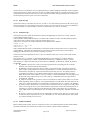
To drive the motor amplifiers and to read the encoders, a VME chassis replaces the old CAMAC interface
in the 30m New Control System.
Juan Penalver wrote already an extended document: 30M Antenna Control with VME Modules.
To summarize, there is a Single Board Computer in slot 1, a Motorola MVME2041 plus a number of
modules to interface the hardware:
• BC366, a VMEbus Time code processor, used for generating different interrupts and to feed a
NTP server.
• IK320, a VMEbus counter card, used to read the Heidenhain ROD800 main axes encoders.
• IK340, a VMEbus counter card, used to read the Heidenhain ROD456 motor encoders.
2
Software development
2.1
Servo controllers
The implementation of the servo controllers is based on the work of Rainer Bardenheuer and his
implementation made 18 years ago. Rainer’s controller software was executed on a CAMAC
microprocessor board and was written in assembler.
In the present implementation, the drives may be in different modes: PRESET, TRACK, INIT, STOP, etc.
PRESET and INIT assume that the axes are driven in velocity. That means that the servomechanisms
receive velocity requests.
TRACK and STOP mean that the positions of the axes are the controlled variables. The servomechanisms
may either receive velocity requests or torque requests. We call, servo controller, the part of this new
software implementation that implements the servo algorithm and establishes the velocity or the torque
requests.
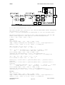
Two bits per axis in the “output register for elevation, azimuth and subreflector control” are used to switch
from one mode of request to the other. In the following, the 2 cases are named basic and cascade.
•
•
In basic, when the position is controlled in a closed feedback, the servo controller implemented in
software is a PI controller. It is the case when the axis is in TRACK mode (variable request =
TRACK) and the servomechanism is in basic (variable track = BASIC). Remark that the
servomechanism is also in basic when the axis is in PRESET or INIT mode. In PRESET, The
algorithm checks in a slow (loose) loop the position error, i.e. the difference between the target
and the actual positions in order to reach the target at maximum speed/acceleration but without
overshoot which would be generated inevitably with only a PI filter.
In cascade, the servo loop always controls the drive position. The servo controller is a cascade of 2
PI controllers (position and velocity), the actual motor positions are feedback and there is a
mechanism of friction compensation.
In the following, the 2 controllers, basic and cascade, in their CAMAC and new VME implementations, are
presented. The names of the variables are the names either used in the source codes or in the manual
Antenna-ServoMechanism from R.Bardenheuer of November 20, 1985.
2.1.1
Basic controller
In the manual “Antenna-servomechanism” page 4-2 the proportional gain is 3 in azimuth and 2.5 in
elevation. The integration time is 5s.
However, the same coefficients are used in the CAMAC implementation (K=3) for both axes.
In the VME implementation we do the same choice, so, the same coefficients are used.
Create Date:November 2001
NCSControl.doc
Author: A.Perrigouard
Page 3 of 19