1
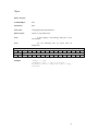
GSI Lumonics Scan Controller User Manual
P/N 7OM-015
Rev 1.21
Revision Date: Dec. 15, 1999
Copyright 1998, 1999 GSI Lumonics, Inc.
GSI Lumonics Scan Controller User Manual
Contents:
1.
2.
3.
4.
5.
6.
7.
8.
9.
10.
System Overview
System Interconnection
Software Overview
Tutorial: Writing Scan Controller programs
Special System Topics
Command Reference
Binary Command Format:
Scan Controller error codes
Binary Interface Definition
Program to generate CRC
System Overview
The Scan Controller is a small intelligent system intended to control one or two axes of the GSI Lumonics SAX family
of scanner servo amplifiers, and associated peripherals. It will work in either a stand-alone configuration or in
conjunction with a host computer. The basic components of a complete system consist of the following:
1.
2.
3.
4.
5.
6.
One or two axes of SAX/Galvo micropositioning
One SC2000 Scan Controller
Cabling
Power Supply
A host computer (for setup and optionally for operation), including software
Other system components interfaced to the Scan Controller
The Scan Controller is programmed through its communications interface (J1) using either the GSI Lumonics supplied
1
LabVIEW™ interface, or customer-designed host-side software. For stand-alone operation, this programming will
result in a sequence of user programs stored in the Scan Controller’
s local nonvolatile (FLASH) memory. These
programs will run automatically at system power-up. For operation in conjunction with a host computer, the system
designer can choose a mode of operation between the controller and the host anywhere on the continuum between totally
autonomous and tightly coupled.
The Scan Controller interfaces directly to the position command, position feedback, and binary communications of one
or two SAX single axis servos. This allows not only full position control of the system, enable and status interlock and
but also allows position feedback, galvo temperature status and calibration information to be read digitally by the host
computer.
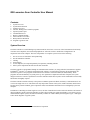
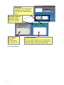
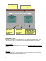
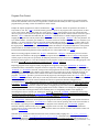
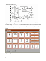
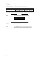
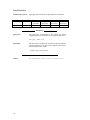
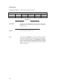
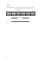
In addition to controlling two SAX single axis servos, the Scan Controller has hooks to aid in the interface and control of
other peripherals typically associated with these systems. These include sync inputs and outputs, a pixel clock system, a
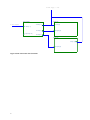
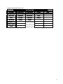
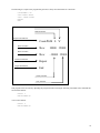
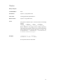
calibration/data capture system, and other functionality available to volume OEM system designers. Figure 1 and Figure
2 show block diagrams of typical systems.
1
2
LabVIEW is a trademark of National Instruments Corporation
SAX
Standard
Serial Port
Scan Controller
host
SAX
Figure 1 Scan Controller with host computer
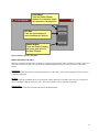
SAX
Scan Controller
SAX
Switches can control
program execution in
standalone operation
Figure 2 Typical standalone system
4
System Interconnection
J7
J2
J6
J3
2.00
.75
J8
J1
4.40
2.50
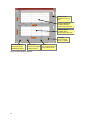
J4
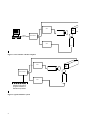
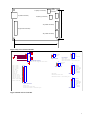
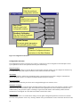
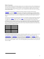
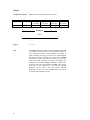
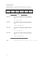
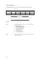
Figure 3: Bracket Assembly
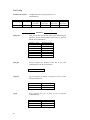
The bracket assembly is shown in Figure 3 (units are inches). The Scan Controller bracket consists of an aluminum Lbracket with two #8 clearance holes located on the riser. The circuit board standoff nearest J4 also serves as the heatsink
mounting point for the 5-volt regulator.
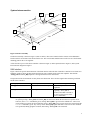
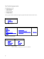
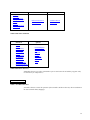
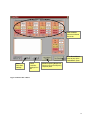
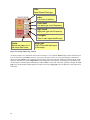
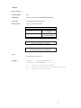
A sketch of the top view of the Scan Controller is shown in Figure 4, with its pinout shown in Figure 5, and a system
interconnection diagram in Figure 6.
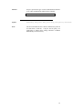
SAX Interface
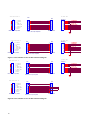
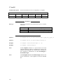
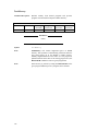
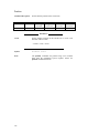
Figure 7 shows the specific interconnection of the SAX interface when the Scan Controller is attached to two SAX servo
amplifiers. Figure 8 shows the interconnection between Scan Controller and a single SAX amplifier. Note that the
~Temp_OK and ~Servo_Rdy inputs have been grounded out for the unused axis.
The operation of the SAX interlock circuitry bears some discussion. There are three signals interconnecting each SAX
and the Scan Controller:
~Servo_Rdy
~Temp_OK
SAX output
SAX thermal controller output
~Servo_Enb
SAX input
indicates functioning servo
indicates temperature in
regulation
required for servo operation
(typically, ~Servo_Enb is
asserted, and within a second or
so ~Servo_Rdy goes true if the
servo is functional)
The interlock system is as follows:
On system powerup, ~Servo_Enb and ~Servo_Rdy are unasserted. When the user desires to operate one or
both axes, the Enable command is given, causing ~Servo_Enb to go low for the enabled axes. After a wait
period of about 2 seconds, the Scan Controller expects ~Servo_Rdy to be asserted, and to stay asserted until the
Disable command is given. Any activity on the ~Servo_Rdy signal until then is cause for an error condition
to be generated, halting program execution, and causing ~Servo_Enb to be unasserted.
5
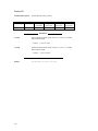
Use of this interlock system is optional –users can simply tie the ~Servo_Enb signal to the SAX low (disconnecting it
from the Scan Controller ~Servo_Enb signal), and similarity tie the ~Servo_Rdy input to the Scan Controller low. This
is shown with the unused axis in Figure 8, and with both axes in Figure 9.
The ~Temp_OK signal is not used in the software interlock, but can be used to qualify conditionals in programs, and can
be read by the host computer (program operation can be delayed at powerup until the system temperature is stable.
Power Supply
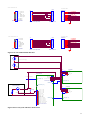
Figure 11 shows the interconnection between the SAX, Scan Controller, and a +/- 15v system power supply. If the
system requires rails higher than +/- 15v, the Scan Controller may need heat sinking in addition to its simple L bracket to
keep its regulator adequately cool. Finding the best system chassis grounding point is a major issue. A single ground
point usually gives best performance. It can be at the Scan Controller, the SAX, the galvo, or the host computer.
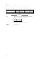
The +5V in/out pin provides additional flexibility. As shown in Figure 10, this can be utilized to drive small auxiliary
loads, like pull-ups on logic lines, or small laser diodes. The available current is a function of the end-user’
s packaging
and rail voltage (the major constraint is heating of the 5v regulator on the Scan Controller). Under some circumstances,
OEM design-ins may choose to utilize an external 5v supply, to minimize dissipation at the Scan Controller. This may be
advisable if very high rails are used for the SAX (+/- 24v).
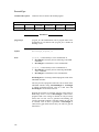
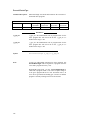
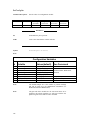
Sync / Cal
The Sync/Cal connector provides access to the synchronization/calibration I/O as well as the pixel clock output of the
Scan Controller. These signals are broken down as follows:
Sync[1..4]
Connector
pins 1-4
Sync[5..8]
Pins 6-9
Sync/Cal[9..12]
Pins 10-13
Sync[13]
NA
Sync[14]
NA
These are open-drain outputs.
They can sink up to 100mA
continuous, and withstand peaks
of 40v
These are CMOS inputs with 10K
Ohm pull-down resistors.
These are CMOS inputs with 10K
Ohm pull-down resistors.
Controls operation of the
position-based Pixel clock (opens
the PLL tracking loop)
Gates the output of the Pixel
clock
Written through the SetSync
and UnSetSync commands.
Read through the WaitSync and
If commands (this allows a
mechanism for inter-program
control)
Read through the WaitSync and
If commands
Read through the WaitSync and
If commands. Also load the
relevant Cal registers on a low to
high transition. These are visible
to the host upon issuing an
?OpticalCal command.
Written through the SetSync
and UnSetSync commands.
Written through the SetSync
and UnSetSync commands.
Figure 10 shows a system using one of the (open drain) sync outputs and the auxiliary 5v output to power and control a
diode laser module. The sync output is used to modulate the lasers light output, and coordinate it with beam motion.
6
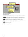
J7 (temp x connector)
J1 (serial connector)
J2
(power
connector)
J6 (temp y connector)
2"
J3 (X SAX connector)
J4 (Sync/Cal connector)
J8 (Y SAX connector)
4"
9
Figure 4 Top view of Scan Controller
J2
J1
J7
2
1
Temp Gnd
Temp X
Temp X connector
serial interface connector
Mates with GSI supplied serial cable
J6
2
1
sync 1 (out)
sync 2 (out)
sync 3 (out)
sync 4 (out)
Sync GND
sync 5 (in)
sync6 (in)
sync7 (in)
sync8(in)
sync/cal 9(in)
sync/cal 10(in)
sync/cal 11(in)
sync/cal 12(in)
Pixel Clock Output
Pixel Clock GND
1
2
3
4
5
6
7
8
9
10
11
12
13
14
15
4
3
2
1
8
7
~RTS RS485out
TXD RS485out
~CTS RS485in
RXD RS485in
1
2
3
4
5
6
J4
.
.
.
.
.
.
.
.
.
.
.
.
.
.
.
Sync / Cal connector
Mates with:
Molex #51021-1500 shell
Molex #50079-8100 or 50079-8000 pins
-Vin
GND
+Vin
+5V in/out
Pwr connector
Mates with:
Molex #51021-0400 shell
Molex #50079-8100 or 50079-8000 pins
Temp Gnd
Temp Y
Temp Y connector
J3
8
7
6
5
4
3
2
1
X
X
X
X
X
X
X
X
FBPOSPFBPOS+
~SERVO_RDY
~SERVO_ENB
~TEMP_OK
GND
-Command
+Command
Y
Y
Y
Y
Y
Y
Y
Y
FBPOSPFBPOS+
~SERVO_RDY
~SERVO_ENB
~TEMP_OK
GND
-Command
+Command
Mate with:
Sax X Axis
Molex #51021-1400 shell
Molex #50079-8100 or 50079-8000 pins
J8
8
7
6
5
4
3
2
1
Sax Y Axis
Figure 5 Pinout of Scan Controller
7
To Power Supply (+/- 15V)
Scan Controller
To Host Computer
SAX X Axis
J2 PWR[1..4]
J1 Pwr[1..4]
J3 SAX[1..8]
J2 Signal[1..8]
J1 Serial[1..6]
J4 Sync/Cal[1..15]
J8 SAX[1..8]
SAX Y Axis
J1 Pwr[1..4]
J2 Signal[1..8]
Figure 6 SAX connected to Scan Controller
8
Scan Controller J3
"X Axis" SAX
CN?
CN?
J3
1
2
3
4
5
6
7
8
X
X
X
X
X
X
X
X
1
2
3
4
5
6
7
8
+Command
-Command
GND
~TEMP_OK
~SERVO_ENB
~SERVO_RDY
PFBPOS+
FBPOS-
Molex 1.25mm 8p header
1
2
3
4
5
6
7
8
647047-8
J2
1
2
3
4
5
6
7
8
+COMMAND
-COMMAND
-TEMP_OK
-SERVO_ENB
-SERVO_RDY
FBPOS+
FBPOS-
AMP 770602-8
Molex 1,25 mm 8p receptacle
Scan Controller J8
J8
Y +Command
1
Y -Command
2
Y GND
3
Y ~TEMP_OK
4
Y
~SERVO_ENB
5
Y ~SERVO_RDY
6
Y PFBPOS+
7
Y FBPOS8
CN?
1
2
3
4
5
6
7
8
Molex 1.25mm 8p header
CN?
1
2
3
4
5
6
7
8
"Y Axis" SAX
647047-8
J2
1
2
3
4
5
6
7
8
+COMMAND
-COMMAND
-TEMP_OK
-SERVO_ENB
-SERVO_RDY
FBPOS+
FBPOS-
AMP 770602-8
Molex 1,25 mm 8p receptacle
Figure 7 Scan Controller to 2X SAX interconnection diagram
Scan Controller J3
X
X
X
X
X
X
X
X
1
2
3
4
5
6
7
8
"X Axis" SAX
CN?
CN?
1
2
3
4
5
6
7
8
+Command
-Command
GND
~TEMP_OK
~SERVO_ENB
~SERVO_RDY
FBPOS+
FBPOS-
Molex 1.25mm 8p header
1
2
3
4
5
6
7
8
J2
AMP 770602-8
Molex 1,25 mm 8p receptacle
Scan Controller J8
1
2
3
4
5
6
7
8
Y
Y
Y
Y
Y
Y
X
Y
+Command
-Command
GND
~TEMP_OK
~SERVO_ENB
~SERVO_RDY
FBPOS+
FBPOS-
CN?
CN?
1
2
3
4
5
6
7
8
Molex 1.25mm 8p header
Figure 8 Scan Controller to 1X SAX interconnection diagram
10
1
2
3
4
5
6
7
8
AMP 770602-8
Molex 1,25 mm 8p receptacle
647047-8
1
2
3
4
5
6
7
8
+COMMAND
-COMMAND
-TEMP_OK
-SERVO_ENB
-SERVO_RDY
FBPOS+
FBPOS-
Scan Controller J3
"X Axis" SAX
CN?
J?
1
2
3
4
5
6
7
8
X
X
X
X
X
X
X
X
+Command
-Command
GND
~TEMP_OK
~SERVO_ENB
~SERVO_RDY
FBPOS+
FBPOS-
1
2
3
4
5
6
7
8
1
2
3
4
5
6
7
8
647047-8
J2
+COMMAND
-COMMAND
1
2
3
4
5
6
7
8
-TEMP_OK
-SERVO_ENB
-SERVO_RDY
FBPOS+
FBPOS-
Molex 1.25mm 8p header
Molex 1.25mm 8p header
AMP 770602-8
Scan Controller J8
CN?
J?
1
2
3
4
5
6
7
8
Y
Y
Y
Y
Y
Y
Y
Y
+Command
-Command
GND
~TEMP_OK
~SERVO_ENB
~SERVO_RDY
FBPOS+
FBPOS-
1
2
3
4
5
6
7
8
1
2
3
4
5
6
7
8
"Y Axis" SAX
647047-8
J2
+COMMAND
-COMMAND
1
2
3
4
5
6
7
8
-TEMP_OK
-SERVO_ENB
-SERVO_RDY
FBPOS+
FBPOS-
Molex 1.25mm 8p header
Molex 1.25mm 8p header
AMP 770602-8
Figure 9 2X SAX without Enable interlock
+15v
System Power Supply
-15V
J1
Scan Controller
To Host Computer
J1 Serial[1..6]
X axis SAX
-Vin
GND
+Vin
~Temp_OK
4
3
2
1
-Vin
GND
+Vin
+5V in/out
J2
4
3
2
1
Pwr connector
J2 Signal[1..8]
Pwr connector
J3 SAX[1..8]
J4 Sync/Cal[1..15]
Laser Diode Module
J1
J4
R1
4.7k pullup
Intensity Control
1
.2
.3
.4
.5
.6
.7
.8
.9
.
10
.
11
.
12
.
13
.
14
.
15
.
sync 1 (out)
sync 2 (out)
sync 3 (out)
sync 4 (out)
Sync GND
sync 5 (in)
sync6 (in)
sync7 (in)
sync8(in)
J8 SAX[1..8]
sync/cal 9(in)
sync/cal 10(in)
sync/cal 11(in)
sync/cal 12(in)
Pixel Clock Output
Pixel Clock GND
Sync / Cal connector
Y axis SAX
4
3
2
1
-Vin
GND
+Vin
~Temp_OK
Pwr connector
J2 Signal[1..8]
Figure 10 Two-axis system with laser diode control
11
+15v
System Power Supply
-15V
Scan Controller
-Vin
GND
+Vin
+5V in/out
J2
4
3
2
1
Pwr connector
Mates with:
Molex #51021-0400 shell
Molex #50058-8100 pins
Figure 11 Typical Power Supply configuration
12
SAX
J1
4
3
2
1
-Vin
GND
+Vin
~Temp_OK
Pwr connector
Mates with:
Panduit CE100F22-8-D
Software Overview
The LabVIEW™ software furnished with the Scan Controller allows users to easily and quickly communicate with the
system. It is intended primarily as an environment for designing and programming stand-alone applications, and for
system evaluation. Pieces of the code can be utilized in host-based real-time systems, but that is not its primary intent.
Other LabVIEW™ code intended for real-time use, as well as Visual Basic support code may become available as the
need arises.
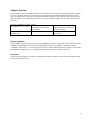
The code is available in a number of forms:
Requires that the user own a
As LabVIEW™ 4.1 or 5.0 VIs
LabVIEW™ programming
environment
Distributed with the system
As LabVIEW™ 4.1 compiled
standalone code
Cost structure yet undetermined –
distribution with or without block
diagrams, etc. TBD
For Win-95 or Win-NT 4.0
systems only
Software Installation
The LabVIEW™ application is presently furnished on CDROM. Alternately, 4 floppy disks can be generated from the
CDROM; read the ReadMe.txt file for the latest information and changes. The software is installed by running
‘
<CDROM>:\install\setup.exe’
. The setup program will create a default installation directory (typically C:\GSI), install
the application and support files, create a program group and add an item in the Windows start menu.
Preparation
Connect the Scan Controller serial cable to an available port on the host computer, connect the SAX modules and turn
the Scan Controller power ON.
13
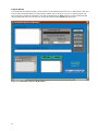
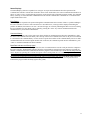
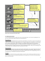
Program Startup
The Command Line Interface program is invoked either from the Windows Start menu or by a double-mouse-click on its
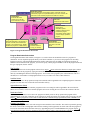
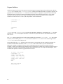
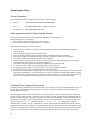
icon (located in the default folder.) The main program window will rise as shown in Figure 12 and the program will
begin executing by running the initialization step. During initialization, the Ready light will remain red indicating that
user operations cannot be serviced. Please do not press any buttons until the Ready light turns green.
Figure 12 CommandLine Interface Main Window
14
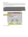
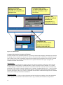
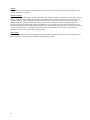
Window Descriptions
The initialization step will automatically raise the Serial Port selector sub-window asking you to set the serial port device
for Scan Controller communications (see Figure 13). The port names used in the program are similar to the Windows
designations, COM1, COM2, COM3 and COM4. Select a port designation either by a left-mouse-click in the body of the
control to view all ports available or by flipping through the list of available ports by left-mouse-clicking on the up/down
triangles. Press Done to enter your selection of serial port.
Expert The Command Line Interface program ‘
remembers’the Serial Port selection while loaded in RAM and the
next time the program is started, it will use the previous Serial Port selection without popping up the Serial Port selector
sub-window. This behavior can cause problems during initial trials on a new computer because an incorrect serial port
may be automatically selected, and the only way to clear the selection is to close the Command Line Interface program
and reopen from disk. A backdoor for this situation is provided by pressing Almost Done after selecting the serial port.
Almost Done will enter your Serial Port selection but will not enable the automatic selection mechanism. If the Comm
Port selection is incorrect, simply 1) stop the program with the Done button, located in the upper right corner of the Main
Window and 2) restart the Command Line; you will be prompted to select a Serial Port once again.
List of available serial ports.
Saves serial port
selection while
program is in RAM.
Configures serial port
for this run only.
Figure 13 Serial Port Declaration
15
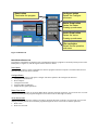
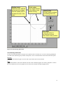
Ready light.
Green when the command line
is ready for a new command.
Red when the command line is
busy.
Baud Rate indicator.
Shows the current
Baud Rate setting of
the host computer.
Error Report.
Errors in
communication
are reported here.
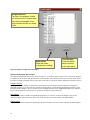
Figure 14 Status Displays
16
Command History
New commands entered in the command line
are saved here. Double click on a selection in
this box to paste it into the Command line.
Status Displays
The Status Displays (shown in expanded view in Figure 14) report back information about the operation of the
Command Line interface with the Scan Controller. Errors can be checked here, the current communications baud rate is
shown, as well as a ‘
busy’signal when the program is involved with a time consuming operation. Finally, the command
history (20 deep) of Scan Controller commands entered in from the command line is available for re-execution with a
simple double-mouse-click.
Error Report
Error messages are reported to the operator through the Communications Error window. If there is a problem talking to
the Scan Controller or if there is some internal error or assembler error, a message will be displayed describing the
problem. In addition, the indicator “
no error”will turn from gray to red clearly indicating that there was an error during
the last command. The error display can be cleared by pressing the <enter> key with no command entered in the
command line, key focus on the command line.
Command History
A list box in the bottom center of the main screen shows the last 20 commands entered from the command line, where
the most recent command enters the history list at the top. If the newest command is the same as the previous command
it is not added to the command history. Use the mouse to operate the scroll bar of the command history list box to find a
command that needs to be entered again. Double click on the line, the command is pasted into the command line, press
<enter> to send the command to the Scan Controller.
Baud Rate Indicator and Ready signal
The Baud Rate Indicator and Ready signal show the state of communication across the serial port from the computer to
the Scan Controller. The Baud Rate indicator shows the current baud rate setting for the host computer. The baud rate
defaults to 2400 baud when the Command Line Interface program is first started. Expert The default startup baud rate
can be adjusted by operating the CLI.EXE front panel control ‘
Startup baud rate’accessable through the CLI.EXE front
panel vertical scroll bar. Stop the CLI.EXE program by pressing the ‘
Done’button and adjust the baud rate. Then resart
the program by pressing the run arrow located in the upper left corner of the main screen. The Ready signal turns from
Green to Red when the Command Line interface program is busy performing an operation. Do not press buttons or
terminate the program while the Ready signal is busy (Red).
17
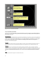
Response Window.
Messages from the Scan
Controller are interpreted and
displayed here.
Command Byte String
The binary command sent to
the Scan Controller, in ascii
hex format.
Readback xlat
The type of readback
translation for
interpretation of a
response to a query.
Command Line.
The Scan Controller can be
interactively controlled by
entering commands here.
Figure 15 Command Line
Command Line Interface Controls and Displays
The Scan Controller can be controlled interactively by entering SC2000 assembly language commands at the command
line prompt, shown in expanded view in Figure 15. There are also facilities that reveal the binary commands sent to the
Scan Controller as the result of Command Line input and certain button activated functions; this allows the Command
Line to be used as a source of binary commands that can be copied and included in other types of programs that
communicate with the Scan Controller.
Command Line
The Command Line is a single line text input box that provides a means of interactive control of the Scan Controller
through SC2000 assembly language commands. With the exception of program creation commands, every SC2000
assembly language command can be entered from the Command Line where the command is checked, assembled and
transmitted via the serial port to the Scan Controller. Query commands, commands that start with ‘
?’
, can be issued and
the Scan Controller response is reported in the Response Window in ASCII hex and decoded form. Each command is
entered by pressing the <enter> key. A history of commands entered from the command line displayed in the Command
History list box located just beneath the command line.
Response Window
The Response Window is where to look for information sent back from the Scan Controller or from the command line
interface program. This information can include the result of query commands, data translations and operational
18
messages. The Response Window is cleared when you enter a new command from the command line or when you
invoke a high level operation from the button pad.
Machine Code Display
A display of assembled binary command data (machine code) is provided as a convenience for developers wishing to
communicate with the Scan Controller in binary format. The Machine Code Display shows the translation of the SC2000
assembly language statement entered from the command line after assembly. The Command Byte string is the binary
data sent to the Scan Controller, the Machine Code. This is displayed in hexadecimal format with the bytes sent to the
Scan Controller in left-to-right order. If the statement entered on the Command Line was a query command, information
is provided on the number of bytes to read back and the type of translation to apply to the readback data.
19
Done button
Terminates the program.
Configure button
Raises the Configure
sub-menu.
Raster Draw button
Raises the Raster
Drawing op sub-menu.
Vector Draw button
Raises the Vector
Drawing op sub-menu.
File ops button
Raises the file operation
sub-menu.
Figure 16 Button Pad
Main Window Button Pad
The majority of the high level functions of the Command Line Interface program are invoked by button presses on the
Button pad (see Figure 16), with the logical structure shown in Table 1.
Done Button
Press the Done button to end the Command Line interface program on the host computer. The Done button does not
affect the operation of the Scan Controller.
Configure Button
Press the Configure button to call up the Configure sub-menu. Options in the Configure sub-menu are:
1. Configure Communications.
2. Host Computer.
3. Configure Pixel clock.
4. Position readback calibration.
5. Adjust and save global parameters.
Raster Draw button
Press the Raster Draw button to call up the Raster Draw operation sub-menu. From here you can invoke one of several
drawing tools that generate programs designed to run in raster mode or dual single axis mode.
Vector Draw button
Press the Vector Draw button to call the Vector Draw operation sub-menu. From here you can invoke one of several
drawing tools that generate Scan Controller programs designed to run in vector mode. Available options are:
1. Draw Circle
2. Draw Free-form line
20
Table 1 Function Button locator tree
*Main Window*
Configure
*Sub-menu*
Raster Draw
*Sub-menu*
Vector Draw
*Sub-menu*
File ops
*Sub-menu*
Serial Port
Load wave
Load circle
Done
Host
HF Sine
Load line
Cancel
Pixel Clock
Cancel
Cancel
Done
Readback Cal
Global Params
Cancel
21
Title text box.
Enter the title of the
program here. The title
is one character in length.
Destination switch.
Select the destination of the drawing object, upload will cause an
assembled program to be uploaded directly to the scan controller, file
will cause a scan controller program to be written to a text file.
File write.
Select the file write method.
AutoRun switch.
(active during
destination:upload
operations) Select autorun
to make the program
execute after upload. Select
normal to simply upload the
program.
Program Type switch.
Select the destination of the program in
the scan controller, flash will store the
program in non-volitile memory, SRAM
will store the program in volitile memory.
Done button.
Press this button to
accept your settings.
Cancel button.
Press this button abort
and return to the main
panel.
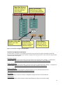
Figure 17 Program Destination sub-window
Program Destination Sub-window
The Program Destination Sub-window (see Figure 17) is used to direct the assembled version of a program to a
destination. You can unpload a program directly to the Scan Controller or you can save the program to an assembly
language source file. The Program Destination sub-window will appear after each high level drawing operation. In
addition to the destination of the program, you can also specify various program attributes such as the program name and
the type of program, flash or volatile.
Title Text Box
Enter a one character title for the program in the text box. Expert do not enclose the character in single quotes. When
you wish to execute the program by typing ExecutePGM from the command line, you must enter a character program
name by surrounding the character with single quotes. You can also call a program by the ASCII character value as a
decimal, hex or octal number. Valid program names are 0-9, a-Z and A-Z as well as other characters.
AutoRun Switch
When AutoRun is set to the up position, interpreted commands will be appended to the compiled program to commence
program execution after it is saved in the Scan Controller memory.
Append/Overwrite Switch
When set to Append, new Scan Controller programs saved to an existing file will be appended to the end of the file.
When set to Overwrite, new Scan Controller programs saved to an existing file will overwrite the contents of the file.
Destination Switch
Use the destination Switch to select where the program will finally reside. In the up position the program will be
uploaded directly to the Scan Controller via the serial port. In the down position, the program will be saved to a file disk.
Expert When a program is saved to disk it retains the Scan Controller storage specification (Flash or SRAM as set
with the Program Type Switch).
Program Type Switch
Use the program Type Switch to select the storage location inside the Scan Controller. The switch is operated by placing
the mouse cursor on the switch graphic and left-mouse clicking. In the up position, the switch will cause the program to
be saved to non-volatile Scan Controller memory by appending the prefix CreateFlashPGM to the program. Expert
Note that flash programs cannot be download to the Scan Controller while a motion program is running. In the down
22
position the switch will cause the program to be saved to volatile memory on the Scan Controller by appending the
CreatePGM prefix to the motion program.
Done Button
When all the options have been configured, press the Done Button to enter the settings and start the program save
operation. Done will return control to the Main window.
Cancel Button
You can press the Cancel button at any time. The program will be lost. Cancel will return control to the Main window.
23
Program text box.
The text of the program is listed
out in this text box. Program edits
from this box propagate to the
scan controller but are not saved
to file.
Done button.
Press this button
to accept your settings.
Cancel button.
Press this button
abort and return
to the main panel.
Figure 18 Upload Configuration sub-window
Upload Configuration Sub-window
The Upload Configuration Sub-window, shown in Figure 18, is raised just before a source-code or ASCII-hex program
is submitted to the assembler and uploaded to the Scan Controller. The window provides a type of stream editor where it
is possible to change commands, add or remove lines or the name of a program without changing the original source file.
Program Text Box
The program text box displays a listing of the program either as Scan Controller assembly language or ASCII-hex
depending upon the type of file read. The scroll-bar on the left allows vertical panning through long programs. Use the
keyboard to make changes to the text, use the mouse to highlight portions of text. Highlighted regions can be copied to
the paste buffer using ctrl-c. Selected text is cut with ctrl-x and text is pasted with ctrl-v.
Done Button
Press the Done button to assemble and upload the program text. If you have not made any changes to the text, the
uploaded program will be exactly the same as the source file. Done will return control to the Main Window.
Cancel Button
Press the Cancel button to quit before uploading to the Scan Controller. Cancel will return control to the Main Window.
24
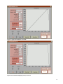
Baud Rate Selector
Select the serial port
baud rate with the
radio buttons.
Number of Stop Bits
Select one or two
stop bits.
Parity Type Selector
Select the type of parity
for serial communications.
Done Button
Press the done
button to make the
desired changes.
Cancel Button
Press the Cancel
button to quit out
of making changes.
Figure 19 Serial Port Configuration sub-window
Serial Port Configuration sub-window
Use this window (see Figure 19) to configure the baud rate, parity and stop bits settings of the RS-232 connection
between the host computer and the Scan Controller. Changes made from this interface will be reflected in both the Scan
Controller and the host computer.
Baud Rate Selector
Click the mouse on one of the radio buttons to select the baud rate for subsequent Scan Controller –Command Line
communications. Expert The power on default baud rate for the Scan Controller is always 2400 baud.
Parity Type Selector
Click the mouse on one of the radio buttons to select the type of parity for subsequent Scan Controller –Command Line
communications. Expert The power on default parity for the Scan Controller is always None.
Number of Stop Bits
Select either one stop bit or two stop bits by clicking the mouse over the embedded pull-down menu.
Expert The power-on default number of stop bits is always one.
Done Button
Press the done button to effect the serial port configuration changes and return to the Main Window.
Cancel button
Press the Cancel button to return to the Main window without making any changes to the serial port settings.
25
Source Type
Use the radio buttons
to select the format
of the source file.
Done Button
Press Done to start
the selected file
operation.
Operation List
Describes the type of
file operation selected.
Cancel Button
Press Cancel to quit
out of any file
operations
Destination Type
Use the radio buttons
to select the format
of the destination.
Figure 20 File Operation sub-window
File Operations sub-window
This window (see Figure 20) provides an interface between the Scan Controller and files on the host computer and also
operates as a translation utility for file formats and downloads of binary program listings from the Scan Controller.
Operation List
The text written here describes, in plain talk, the type of operation that will be performed.
Source Type Selector
Use the mouse to declare the format of the source file (the file to be read). Expert Scan Controller source not currently
supported.
Destination Type Selector
Use the mouse to declare the format of the destination file (the file to be written). Select ‘
Scan Controller’to download a
program file from the computer to the Scan Controller.
Done Button
Press the Done button to begin the desired operation. If the source and/or destination involve files on the host computer,
you will be prompted for file names from pop-up file dialog boxes.
Cancel Button
Press the Cancel Button to quit out of any file operations and return to the Main Window.
26
Load Wave
Calls the Raster-Master
window for interactive single
axis waveform development.
HF Sine
Calls the modulated sine
wave development window.
Cancel button
Close the Raster Drawing
sub-menu and return to
the Main Window
Figure 21 Raster operation sub-menu
Raster Operations sub-menu
Interactive tools from this sub-menu (see Figure 21) generate raster programs such as periodic sine, triangle, square, and
sawtooth waveforms for single axis control and also modulated high-frequency sine wave programs for pixel clock
control.
Load Wave
This button invokes the period waveform generator utility. Use this utility create a raster scanning waveform as a Scan
Controller program file.
HF Sine
This button calls the modulated sine wave development window which takes a periodic raster scan wave as input and
uses it to modulate a high frequency sine wave. The result is stored as a Scan Controller program file.
Cancel button
Press this button to close the sub-menu and return to the Main Window.
27
Serial Port
Calls the serial port
configuration window.
Host
Calls the host computer
configuration panel.
Pixel Clock
Calls the pixel clock
configuration window.
Readback Calibration
Run the Position Readback
calibration procedure.
Global Params
Set certain global parameters
and optionally save to Flash.
Cancel
Close the Configure sub-menu
and return to the Main Window.
Figure 22 Configuration sub-menu
Configuration sub-menu
The configuration sub-menu (see Figure 22) is used as a jump point to various configuration tools that adjust various
system parameters such as serial port baud rate and pixel clock settings.
Serial Port button
Press the Serial Port button to invoke the RS-232 setup window. From this window you can configure the baud rate (up
to 115.2K baud) , parity and stop bits of both the Scan Controller and the host computer.
Host button
Press the Host button to call the host configuration panel. Current support for one option, configure Command Line
Interface Program to operate on computers with limited RAM with a speed tradeoff.
Pixel Clock button
The on-board Scan Controller pixel clock can be configured through a user interface screen.
Readback Cal button
The CLI will interactively control the Scan Controller and the X and Y SAXes via the serial interface to produce a linear
calibration of the position readback signal. This calibration will be uploaded to the Scan Controller and saved to nonvolatile memory. The procedure requires a working X-Y galvo head with SAXes either manually enabled from the
command line or through the use of the hard wired enable SAX interface cables.
Global Params
This button will invoke a screen that allows editing of certain global configuration parameters for the Scan Controller.
The value of the parameter can be set by entering a number in the provided numeric control. Check the check box to alter
28
the parameter. Parameters are altered once the ‘
Done’button is pressed and only those parameters ‘
checked’will be
changed. The current value of all parameters can be save to non-volitile RAM by checking the ‘
Save to Flash’check
box.
Cancel button
Press the Cancel button to close the configuration sub-menu and return to the Main Widow.
29
Load circle
Call the interactive
circle drawing window
Load line
Call the interactive freeform line drawing window
cancel
Close the Vector
sub-menu and return
to the Main Window.
Figure 23 Vector Drawing Sub-menu
Vector Drawing sub-menu
The Vector Drawing sub-menu (see Figure 23) allows you to select one of a number of high level vector drawing tools
used to develop Scan Controller programs for X-Y systems.
Load Circle
Press the Load Circle button to call the circle drawing program where you can draw absolutely positioned circles or
relative circles. Circle programs are stored as Scan Controller assembly language files.
Load Line
Press the Load Line button to call the freeform line drawing program. Use the mouse to draw a freeform, two
dimensional line on the canvas. The line is represented as a continuous spline curve with adjustable knot point distance.
A line drawing program is stored as a Scan Controller assembly language file.
Cancel
Press Cancel to return to the Main Window.
30
Max normal error
Adjust the knob with the
mouse to vary the granularity
of the vectorization of the curve.
Radial auto mark
Adjust the knob with the
mouse to vary the smoothness
of the line drawing.
Vector Drawing Canvas
Draw the line here by
grabbing the cross hairs
with the mouse and leftbutton-down moving the
mouse along the motion path.
No repeat
TRUE (up) to generate a
program that does not repeat.
restart
Clear the drawing and start a
new one at the current cursor
location.
Cursor Cross Hairs
The cross hairs show the
current point in the drawing.
Segment visibility
Show: The next segment will be rendered.
Hide: The next segment will be hidden.
Done Button
Press Done to continue
processing the drawing.
Figure 24 Free-form line drawing sub-window
Line Drawing sub-window
Use the Line Drawing window (see Figure 24) to create freeform motion paths. A line is drawn by grabbing the crosshair cursor with the mouse and then tracing out the motion path desired.
Max normal error
This knob controls the maximum normal error between the approximation vector and an arc of the curve the endpoints of
which lie on the head and tail of the approximation vector. For a given setting of this ‘
max normal error’control, a head
to tail sequence of vectors will be generated along the curve such that the length of a line normal from a given vector to
the curve arc that it approximates will never exceed the control setting. This is the manner of converting curved
trajectories to Scan Controller programs. The vectorization sub-panel is not available for line drawings as it is in circle
drawing but the effect is the same. See the section “
Circle vectorization sub-window”and try the circle drawing tool for
a visual example of the vectorizing effect of the ‘
max normal error’control.
Radial Auto-Mark
This knob controls the spacing of knot points along the spline interpolated line. Larger settings of radial auto-mark result
in smoother lines, but also lines which do not always travel the exact path traced by the mouse. Settings of 0.01 to 0.4
have the greatest effect in drawing detail and overall smoothness. Radial auto-mark can be changed during the course of
a line drawing to get a combination of smooth lines and fine detail.
No repeat
The action of this switch when in the up position (TRUE) is to generate a Scan Controller program that does not have a
repeat statement. The effect is such that when the program is run, the path traced is one traverse of the drawn path and
then the end of the program.
31
Restart
Press this button to clear the current drawing and reset the start point to the current cursor location. This allows you to
start the drawing were you want.
Segment visibility
There are two types of lines drawn, ‘
shown’and ‘
hidden’
. The segment visibility is set before the line is drawn. ‘
Shown’
lines are displayed on the computer screen in black and ‘
hidden’lines are shown in red. Please note also that when the
‘
segment visibility’control is changed the spline for that segment is closed. This closure generates a corner at the
endpoint of the previous spline and the start of the next spline. The end and start points are coincident but the first
derivatives from the left and from the right may be different. Traversal of this corner may cause inertial mirror effects
not present during the traversal of the spline interpolated curve. The mechanism of turning the laser on and off is to insert
‘
setsync 1’and ‘
unsetsync 1’commands at the corners. If other sync channels are to be used for laser control, the
program can be saved as a file and edited with a text editor.
Done button
Press the Done button to convert the drawing into a Scan Controller program, after which you will be prompted to save
the line drawing as a file in the Scan Controller assembly language format.
32
Radius cursor
Grab the cursor with the
mouse and move away
from the center point to
increase the size of the
circle.
Circle center
The original location
of the radius cursor
before moving.
Done button
Press Done to continue
processing the circle.
Re-center
Press this button to
re-center a circle on
the current cursor position.
Figure 25 Circle drawing sub-window
Circle Drawing sub-window
Use the Circle Drawing window (see Figure 25) to generate circles of various sizes. A circle is drawn by grabbing the
cross-hair cursor and moving away from the center point; a circle is rendered with its center at the initial cursor point.
Recenter
Press the recenter button to begin a new circle with a center at the current cursor location.
Done
Press the done button to convert the rendered circle into a Scan Controller program. You will be prompted to vectorize
the circle and then save the circle program as a file in the Scan Controller assembly language format.
33
Max normal error
Adjust the knob with the
mouse to vary the granularity
of the vectorization of the curve
No repeat
TRUE (up) to generate a
program that does not repeat.
reference
absolute: circle is drawn in absolute coordinates.
Relative: circle is drawn relative to the current
position at run-time.
Done
Press the ‘
done’
button to accept
the vectorization of the circle.
Figure 26: Circle vectorization sub-window
Circle vectorization sub-window
Use the Circle vectorization sub-window to convert the smooth curve circle into a group of vectors that approximate the
path of the circle. This tool allows curve generation in the Scan Controller by providing a tradeoff between program size
and smoothness of the curve.
Max normal error
This knob controls the maximum normal error between the approximation vector and an arc of the curve the endpoints of
which lie on the head and tail of the approximation vector. For a given setting of this ‘
max normal error’control, a head
to tail sequence of vectors will be generated along the curve such that the length of a line normal from a given vector to
the curve arc that it approximates will never exceed the control setting. This is the manner of converting curved
trajectories to Scan Controller programs.
No repeat
The action of this switch when in the up position (TRUE) is to generate a Scan Controller program that does not have a
repeat statement. The effect is such that when the program is run, the path traced is one revolution about the circle.
Reference
Circle programs may be generated using either absolute positioning commands or relative positioning commands.
‘
Absolute’will cause a circle program to be generated which contains slewxy commands. Positioning in the field of view
is directly tied to the origin of the drawing screen. ‘
Relative’will cause a circle program to be generated which contains
deltaslewxy commands. Positioning in the field of view is relative to the current mirror position before the program is
run.
Done
Press the ‘
Done’button to accept the vectorization of the circle.
34
Operating the Scan Controller
Once the CLI program is initialized, the Ready light on the CLI main panel should turn green, indicating that the
Command Line Interface program is in the idle state. Single line SC2000 assembly language commands can be sent to
the Scan Controller by typing in the Command Line box. Press <enter> to assemble the command and send the binary to
the Scan Controller over the serial line. High-level interface tools are started by raising a sub-menu of operations with
one of the buttons located on the right side of the main window. The Command Line Interface assembler will perform
error checking on programs submitted from files and immediate commands entered from the Command Line and error
reports will be generated in the case of out of range arguments, illegal or improper commands, etc.. SC2000 assembly
language commands are documented in the Reference section at the end of this document.
An example of typical operation is as follows::
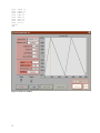
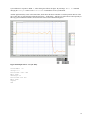
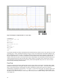
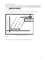
1. Raster Draw / Load Wave: This brings up the window shown in Figure 27. Signal Source provides the means to
select the basic wave-shape. Frequency and Amplitude (in peak volts, of the commanded wave-form) can be
entered in the appropriate places. Offset will adjust a DC offset term which is added to the wave-form, and the
phase variable sets the location the ‘
repeat’statement. Ticks per sample controls how finely the waveform is
broken up into straight-line segments. The Scan Controller codec operates at a constant update rate of 43.411 kHz (it
outputs command voltages to the galvo at this constant rate). One way of generating wave-forms is to store one
point for each point output to the galvo. For many applications this is unnecessary –the program can be made of
many fewer points, and the Scan Controller will generate straight lines between them using the slewxy or slew
commands. The Ticks per sample control controls this granularity. When it is set to 1 a command is generated for
each point to the galvo –if it is set to 10 then a command is generated for every ten points, and straight lines are
drawn between them. For 'Ticks per Sample' of one, this control re-names itself Periods and allows multiple periods
of a waveform to be generated. This is useful for generating higher frequency waveforms. The waveform plot shows
the effects of varying these controls, in real-time. Finally, the derivitator control allows the display and generation
of the time derivative of the wave-form. This can be useful where velocity, rather than position is the variable of
interest. When the desired wave-form is present in the plot, pressing the Done button brings up the Program
Destination Window, shown in Figure 17. This allows you to direct the program to the Scan Controller or store to a
file on the host. The title is any single character, which will be converted to a number by the program (the program
describing this sine wave is called ‘
a’
).
2. File Ops source code Scan Controller: This allows you to take an already created program stored on the host
and load it to the user interface. The sine wave program created above has the listing shown below, and can be
assembled and sent to the Scan Controller using the file ops window, shown in Figure 20.
CreatePGM 0 'a'
Slew 1897 13
Slew 3898 13
Slew 5759 13
Slew 7411 13
Slew 8795 13
Slew 9862 13
Slew 10572 13
Slew 10900 13
Slew 10834 13
Slew 10377 13
Slew 9544 13
Slew 8367 13
Slew 6887 13
Slew 5158 13
Slew 3243 13
Slew 1211 13
Slew -866 13
Slew -2911 13
Slew -4850 13
Slew -6615 13
Slew -8140 13
Slew -9371 13
Slew -10264 13
Slew -10785 13
Slew -10917 13
35
Slew -10654 13
Slew -10006 13
Slew -8996 13
Slew -7662 13
Slew -6050 13
Slew -4220 13
Slew -2237 13
Slew -173 13
repeat
end
Figure 27 Load wave window
36
Tutorial: Writing Scan Controller programs
Author: Fred Stewart
Date: 06-02-99
Introduction.
The GSI Lumonics Scan Controller accepts a motion program language that consists of a binary machine language. Scan
Controller assemblers and assembler components are provided by GSI Lumonics to allow the motion application
developer to use English language commands for controlling single axis, dual single axis and dual axis motions as well
as interactive control of the Scan Controller. The full range of motion control expression native to the binary machine
language is available through the use of the SC2000 assembly language. This document is a tutorial and application note
to help the motion application developer understand and use the SC2000 assembly language in conjunction with a Scan
Controller assembler.
37
Quick Start.
Scan Controller programs are typed into a text file with a text editor such as Wordpad (save with text only option).
Expert It is not possible to enter a Scan Controller program from the Command Line prompt, you must use a file.
There are two basic operating modes in the Scan Controller. Vector mode is used to simultaneously control X and Y axis
galvos to produce vector drawing. Raster mode is used to control a select single axis. Vector commands can be
distinguished from raster commands by the presence of an ‘
xy’suffix. For example, ‘
Slewxy’is a vector command and
‘
Slew’is a raster command.
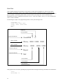
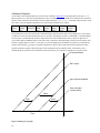
The following is a simple vector program that generates a slowly traced 45 degree line:
CreatePGM 1 ’a’
Slewxy 10000 10000 32000
Slewxy –10000 –10000 32000
Repeat
End
Program ID
Vector declaration
Program head statement
CreatePGM 1 ‘
a’
Motion command
Slewxy 10000 10000 32000
Motion command
Slewxy –10000 –10000 32000
Control flow statement
Repeat
Program tail statement
End
X axis parameter
Y axis parameter
Time parameter
This program can be executed by uploading the program and then entering the following command at the command line:
vector
ExecutePGM
38
’a’
The following is a simple raster program that generates a slowly traced horizontal or vertical line:
CreatePGM 0 ’b’
Slew 10000 32000
Slew –10000 32000
Repeat
End
Program ID
Raster declaration
Program head statement
Motion command
CreatePGM 0 ‘
b’
Slew
10000 32000
Slew
–10000 32000
Motion command
Control flow statement
Repeat
Program tail statement
End
position parameter
Time parameter
This program can be executed by uploading the program and then entering the following commands at the command line
for horizontal motion:
Raster 1
ExecutePGM ’b’
or for vertical motion:
Raster 2
ExecutePGM ’b’
39
Scan Controller language overview.
Keywords fall into six groups:
1. Semantic directives
2. Flow control statements
3. Motion statements
4. Side effect statements
5. Immediate directives
6. Assembler directives
Of the six groups, immediate commands cannot appear in programs and semantic statements cannot be nested.
Vector & Raster
CreatePGM
CreateFlashPGM
End
Table 2 Semantic directives
Vector & Raster
Repeat
NRepeat
ExecutePGM
Wait
Waitsync
If <sync> ExecutePGM
If TempOK <device> ExecutePGM
ExitPgm
AbortPgm
Vector
ExecuteRasterPGM
If <sync> ExecuteRasterPGM
If TempOK <device> ExecuteRasterPGM
WaitPositionXY
Table 3 Flow Control statements
Vector
Raster
PositionXY
SlewXY
DeltaPositionXY
DeltaSlewXY
Position
Slew
DeltaPosition
DeltaSlew
Table 4 Motion Command statements
(Motion commands are divided into raster and vector commands)
40
Raster
WaitPosition
Vector & Raster
Setsync
Unsetsync
DelayedSetSync
DelayedUnsetSync
Enable
Disable
ConfigPixelClock
ComConfig
Vector
Raster
DeltaTweakAxisXY
TweakAxisXY
DeltaTweakAxis
TweakAxis
Table 5 Side effect statements
Directives
Queries
Raster
Vector
PackMemory
ReleasePgm
SetConfigVar
SetGSS
SetXPROffset
SetXPRGain
SetYPROffset
SetYPRGain
SetSetSyncDelay
SetUnsetSyncDelay
SaveConfigInFlash
?FreeFlashSpace
?FreeRAMSpace
?ID
?Position
?Temp
?TempOK
?OpticalCal
?Status
?Sync
Table 6 Immediate directives
(Immediate directives are either commands or queries and cannot be included in programs. They
are listed here for completeness.)
Directives
#
Table 7 Assembler Directives
(Assembler directives control the operation of the assembler and do not have any direct translation to
the Scan Controller binary language.)
41
Program Definition.
Semantic statements are directives that cannot be nested in programs. Programs begin with a head statement, either the
‘CreatePGM’statement or the ‘CreateFlashPGM’ statement. The header statement of a program is required. All
programs have a tail statement, the ‘end’statement. The tail statement of a program is required. In between the head
and tail statements a program can contain synchronization and flow control statements and raster or vector motion
statements. Note that raster and vector motion commands cannot be mixed in one program. Thusly, a program is
declared to be either as raster or vector by the first parameter of the head statement.
CreatePGM 0 ’r’
statement
.
.
.
statement
end
‘CreatePGM’and ‘CreateFlashPGM’take the same parameters. Parameter-1 is the program type: ‘0’for raster
programs and ‘1’for vector programs. Parameter-2 is the name or program-ID written in any number format valued
from 1 to 255.
The ‘end’statement signifies the end of the program identified by program-ID. ‘CreatePGM - end’pairs cannot
be nested; if the assembler parses a ‘CreatePGM’directive before an ‘end’directive after encountering an initial
‘CreatePGM’directive it will flag an error.
The text that follows the ‘end’statement can be either directives or statements; the Scan Controller assembler will
assemble commands inside and outside of the‘CreatePGM’mode context and it is up to the communications
application to manage coordination of directive, query and program operation of the Scan Controller. Therefore,
assembler is capable of assembling single statements from a command line, multiple Scan Controller programs written in
a single file or a mixture of Scan Controller programs and immediate directives. For example, the following file, when
assembled and uploaded, will define a program and then execute it.
# render a box shape
CreatePGM 1 ’a’
Slewxy 1000 1000 500
Slewxy –1000 1000 500
Slewxy –1000 –1000 500
Slewxy 1000 –1000 500
Repeat
End
#run the program
ExecutePGM ’a’
42
Program Flow Control
Scan Controller programs run in the standard sequential statement execute style; the statements are executed in order
from the first statement to the second, etc. Program flow control statements modify the basic sequential execution of a
program thereby providing a richer environment for motion control.
Perhaps the simplest program flow control command is the ‘Wait’statement. It takes one parameter, the number of
23S counts to wait. The ‘Wait’statement basically generates a pause in the program at the current position, in either
vector or raster mode. When in dual single axis vector mode, a ‘Wait’in the program of one axis will not affect the
other axis program. Note that the time paused is unconditional, the program will not continue until the wait timer expires.
While the ‘Wait’command is unconditional, the ‘Waitsync’command allows a variable length program pause by
stopping the program at the current position until a signal is received on a sync pin. ‘Waitsync’takes one parameter, the
sync channel number. A read only sync channel (5 - 12) can be wired to an external sensor or button, or a read/write sync
channel (1 - 4) can be shared between two programs running dual single axis mode. ‘Waitsync’is valid in both vector
and raster modes. ‘WaitPosition’and ‘WaitPositionXY’are used to pause program execution until the galvo reaches
the target position. These commands operate in the same manner as Waitsync except that the RMS value of the position
readback buffer is used rather than the value of the sync channel. Tolerance of this command to position error can be
tuned with the WaitPosition parameter and by adjusting the size of the sample buffer (see SetGSS) .
When an executing program encounters the ‘Repeat’command or the ‘NRepeat’command, the point of execution
returns to the first statement of the program and execution proceeds from there. In the case of ‘NRepeat’the program
will only repeat as many times as specified by the NRepeat parameter (N times), then it will fall through to subsequent
instructions in the program or, if it is the last statement in the program, execution will return to the calling program or the
idle mode. Expert A given program may contain only one‘NRepeat’statement.
Repeating programs can be stopped (actually all programs are stopped) by issuing the ‘AbortPGM’or ‘
ExitPGM’
commands from the command line. Programs can also be stopped by creating a ‘
stopper program’that contains just the
‘ExitPGM’or ‘AbortPGM’statement. Arrange to have this program run as the result of a conditional test of a sync pin
or a temperature signal. When the condition asserts and the point of execution arrives at the conditional statement, all
running programs will stop and the Scan Controller will return to immediate command mode. In terms of stopping
programs, ‘ExitPGM’ provides a graceful exit from the program by cancelling the action of all ‘repeat’and ‘if <sync
channel 1,2,3 or 4>’statements. There may be some delay between the time that the ExitPGM command is issued and
when the program stops. Issue the ?status command and wait for a response that identifies Exitpgm success
(0x000000250000). Expert sync inputs (channels 5-12), WaitPositionand WaitPositionXY statements are not affected
by ExitPgm.‘AbortPGM’ terminates the program as soon as possible also disabling the servos. Expert AbortPgm
will disable both SAXes. The choice of these two modes of stopping along with other commands in the ‘
stopper
program’provide a flexible means of stopping programs under various conditions. For example the ‘
stopper program’
can also perform other cleanup operations such as disabling lasers or extinguishing machine vision lighting by
controlling these devices from the sync channel pins. Expert Issuing the ‘ExitPGM’command on non-repeating
programs has no effect except for ‘if <sync channel 1,2,3 or 4>’, so given a program that you wish to stop that contains
particularly long slews, the appropriate command for immediate halting is ‘AbortPGM’.
The ‘ExecutePGM’statement is used to spawn a new program from inside a parent program and could be classified as
an unconditional branch statement. ‘ExecutePGM’is sensitive to the current operating mode of the Scan Controller. If
the controller is operating in Vector mode, only vector programs can be started by the ‘ExecutePGM’program
statement. Similarly in Raster mode, only new raster programs can be executed, with the additional constraint that
execution always occurs on the same axis as that of the parent. Please note also that the Scan Controller has a finite call
depth for ‘ExecutePGM’.
Somewhat more formalized conditional statements in the SC2000 assembly language are ‘If <sync channel>
ExecutePGM’ and the ‘If TempOK <device> ExecutePGM’statements. These are simple ‘
if’clauses; ‘
else’
clauses are not supported. Expert The entire program statement must be written on one line. The two flavors of ‘
if’
statements support program spawning from an external signal (sync channels 5 - 12) or internal flag (sync channels 1 - 4)
43
and program spawning under the control of the axis servo temperature with the TempOK <device> form. Both are
available in vector and raster modes.
Forms of previously discussed flow control statements are available (when in vector mode) to begin yet another
execution mode called the dual single axis mode. Dual single axis mode will execute two raster programs concurrently,
one on the X-axis and one on the Y-axis. The standard program invocation ‘ExecuteRasterPGM’ will commence
the dual single axis mode from vector mode. The command takes two arguments, Arg-1 is the X-axis program and Arg-2
is the Y-axis program. Similarly, the conditional statements that start the dual single axis mode take X-axis and Y-axis
arguments. These commands are ‘If <sync channel> ExecuteRasterPGM’and ‘If TempOK <device>
ExecuteRasterPGM’.
44
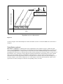
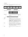
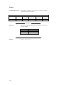
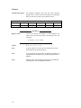
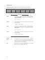
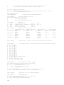
Motion Commands
Motion commands exhibit the most thorough symmetry between vector and raster modes of all the command groups. For
each vector motion command there is a corresponding raster motion command. The coordinate values of all the absolute
motion and positioning commands range from –32768 to +32767 and correspond to voltages on the SAX drive pins,
where –32768 3.1 Volts, 32767 -3.1 Volts and 0 0.0 Volts. Command values outside of this range will be flagged
as errors by the assembler.
In the SC2000 assembly language the fundamental positioning command is the absolute position statement
‘PositionXY’for vector and ‘Position’for raster. The vector form takes two parameters, the X-coordinate and the Ycoordinate while the raster form takes just one parameter, the coordinate. The position commands will cause the servo
control voltage to change very rapidly, in effect “
setting”the position of the galvo. This change in position command can
happen faster than the servo driver can keep up, so thought must be given towards total system response to large step
changes.
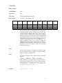
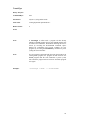
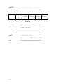
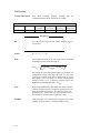
Large steps can be programmed in a smoother manner with the slew commands. The absolute positioning slew statement
for vector mode is ‘SlewXY’and for raster mode it is ‘Slew’. The vector slew command takes three parameters, the
X-coordinate, the Y-coordinate and the count. X and Y coordinates have the same range as above in the position
commands. The count parameter has a value for 1 to 32767 and represents the number of 23 S ticks that pass while the
line is drawn to the new coordinate. The path control voltage during a slew is a linear ramp from the current position to
the new absolute position over the course of <count> ticks. In raster mode this is just a simple smooth ramp. In vector
mode, two concurrent ramps are generated, possibly different in slope, start point and end point, the only common factor
being the time it takes to complete each ramp.
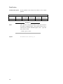
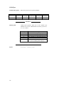
Tick counts
Time (seconds)
433
0.0100163725
4323
0.1000017975
21615
0.500017975
43230
1.000017975
65535
1.515988
2
155625203
3600.0000084
1
4294967296
99353.33097
Table 8: Tick count vs. time
The positioning commands described above operate in the absolute coordinate system of –32768 to +32767 for X and Y
axis. Another set of SC2000 commands operate using relative coordinates. In vector mode these statements are
‘DeltaPositionXY’and ‘DeltaSlewXY’and in raster mode they are ‘DeltaPosition’and ‘DeltaSlew’. Again, the
vector deltaposition command takes two parameters, the X-axis parameter and the Y-axis parameter but instead of
indicating the target coordinates absolutely, the parameters indicate an offset relative to the current position (here current
position is the last commanded position value, not the reading of the position detector.) Limits for the offset value are the
same as for the position commands, -32768 to +32767. The count parameter specifies the number of ticks to pass for the
motion to complete.
1,2
32 bit count for ‘
wait’statement
45
Side Effect Statements
Side effect statements are used to control devices or channels in ways that do not involve motion control of the galvo.
Certain commands operate with zero cycle overhead, making it possible after fully specifying a motion program with
slew and position statements, to insert side effect statements for the purpose of control and synchronization without
affecting the validity of the independently developed motion program.
The most fundamental side effect statements are ‘enable’and ‘disable’, which are used to enable and disable the
SAX servo boards. ‘enable’and ‘disable’each take a single parameter, the device specification. 1 is the X-axis,
2 is the Y axis and 3 specifies both axis for simultaneous enable or disable both SAXes at the same time. It is important
to note that SAX modules must be enabled before they can servo command voltages. Enable and disable can be issued
from inside a program making it possible to operate SAX boards according to conditions detected at the temperature or
sync pin inputs as well as at the beginning and end of a program.
‘SetSync’and ‘UnsetSync’operate on the first four sync channels. These four are different from the other eight
sync channels in that they can be both written to and read out. Each command takes one argument, the sync channel
specification, valued from 1 to 4. The hardware pins corresponding to the sync channel are located in J4. Channel 1
operates pin 1, channel 2 operates pin 2, etc. The ‘SetSync’command turns on an open drain MOSFET causing the
J4 pin to sink current through to J4 pin 5. ‘UnsetSync’turns the open drain MOSFET off leaving the pin in a high
impedance state with respect to pin 5. The read operation for these sync channels references the ‘
internal output port
mirror register’
, not the logic level present on the pin. ‘SetSync’and ‘UnsetSync’can also be used internally by
programs providing a simple flag mechanism that two programs can use for communication when running in dual single
axis mode. In this manner of operation, no external connection is required. Two related commands are
‘DelayedSetSync’and ‘DelayedUnsetSync’and their action is exactly the same as ‘SetSync’and
‘UnsetSync’except that the transistor action occurs some number of ticks after the command is executed in the
program. The delay is specified in a global configuration variable, typically set to compensate for Codec and servo
delays.
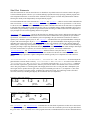
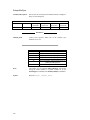
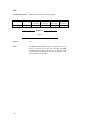
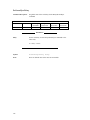
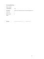
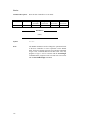
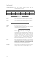
‘DeltaTweakAxisXY’, ‘DeltaTweakAxis’, ‘TweakAxisXY’ and ‘TweakAxis’are used to adjust the
gain and offset correction factors on the fly. ‘DeltaTweakAxis’and ‘TweakAxis’are used in raster mode and
‘DeltaTweakAxisXY’and ‘TweakAxisXY’ are used in vector mode. The ‘DeltaTweakAxis’commands
take two kinds of parameters, gain and offset, which are processed as deltas or incrementals of the current correction
values. The gain parameter is a floating-point value ranging between 0.5 and 1.5. This gain delta is multiplied by the
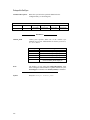
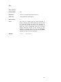
current gain value to produce the new gain value (the power-on default gain value is 1.0, see Equation 1.) The offset
incremental, a positive or negative integer, is added to the current offset value, the result being stored as the offset
correction, effectively relocating the origin by the incremental value (see Equation 2).
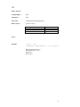
Equation 1: Delta Gain equation
1.32
New
gain value
= 1.2
x
Previous
gain value
1.1
Gain
Delta value
Equation 2: Delta Offset equation
27
= 25
New
offset value
+ 2
Previous
offset value
Offset
Delta value
The ‘TweakAxis’ and ‘TweakAxisXY’commands take the same kinds of parameters as those above but instead
of being deltas they are the actual gain or offset value and the action of the command is just to set the gain and offset to
the given values. These commands can be either program statements or immediate directives and care should be taken to
46
understand the operational context in which these commands are executed. Typically, ‘TweakAxis’and
‘DeltaTweakAxis’ can only be instructions in a raster program or can only be entered when a raster program is
running. Similarly, ‘TweakAxisXY’and ‘DeltaTweakAxisXY’can only run in the vector context. Of special
interest is the Dual Single Axis mode initiated by the ‘ExecuteRasterPGM’ command. From the outside, this mode
is the same as vector mode, and you should enter ‘TweakAxisXY’ or ‘DeltaTweakAxisXY’as a concurrent
immediate directive. From the inside (in the context of the running programs) the Scan Controller is in raster mode and
the statements ‘TweakAxis’ or ‘DeltaTweakAxis’should be used in programs.
The ‘?Position’command will readback the current position of the galvo as reported by the galvo’
s position sensor.
This reading has a two point calibration associated with it making it possible to calibrate the readback value of the galvo
to the commanded position. Calibration values are entered with the commands ‘SetXPROffset’, ‘SetXPRGain’,
‘SetYPROffset’, and ‘SetYPRGain’ and the values relate the readback value to the raw position sensor reading
with the following formula: PRead axis PRGainaxis PRawaxis PROffset axis . Calibration values as entered with
these commands are in volatile memory. Calibration values can be stored in non-volatile memory by using the command
‘SaveConfigInFlash’and when the Scan Controller is power-cycled, the saved configuration values will be
automatically loaded. Subsequent execution of the commands ‘SetXPROffset’, ‘SetXPRGain’,
‘SetYPROffset’and ‘SetYPRGain’will adjust the current calibration values, but unless the
‘SaveConfigInFlash’command is executed, the updated calibration values will be lost when the Scan Controller
is power cycled, and the values restored upon power-cycle will be the values stored in flash.
The command ‘SetGSS’adjusts size of the ‘WaitPosition’sample buffer for both the X and Y axis. This size
can be any value from 1 to 100. It is saved to flash at the same time as the above parameters by using the
‘SaveConfigInFlash’command and modification of the run-time value is the same as above. The Global Sample
Size determines the number of position values used in the RMS computation of error from target. In the time domain the
Global Sample Size determines the size of a sliding window that holds a finite position readback history.
Two additional configuration variables stored into Flash memory by the ‘SaveConfigInFlash’command are the
tick delay values stored by the ‘SetSetSyncDelay’and ‘SetUnsetSyncDelay’ commands. These delay
values are used by the commands ‘DelayedSetSync’and ‘DelayedUnsetSync’. There are separate global
delays for the Set and Unset versions; each ‘DelayedSetSync’command in a program has the same delay, but this
can be different from the ‘DelayedUnsetSync’delay. Expert If the delay time is longer than the total tick count
of a short, repeating program, a stack overflow error will result. Expert The delayed signal will continue to operate
after a program has completed.
47
Immediate Directives
Immediate directives are commands and queries that cannot be executed from within a program and will not be covered
as a group in this section. Certain commands are of special interest, however. ‘Raster’and ‘Vector’are the
statments used to set the operating mode. ‘Vector’is used to set the operating mode for vector programs and dual
single axis programs. ‘Raster’takes one parameter, the axis specifier, and causes all programs declared as raster and
all raster commands to be executed on the specified axis. Note that the operating mode of the Scan Controller is checked
by the firmware before executing a command or program. If the operating mode, raster or vector, does not match the
command type, an error will be raised and all further commands will be ignored. This error must be cleared by the
?status command. Finally, ‘ReleasePGM’is used to remove a program from memory and takes one parameter, the
program name. The Scan Controller needs to be power cycled before memory can be reclaimed from the non-volatile
memory. Programs that have been released but that reside in SRAM memory can be removed and space reclaimed by
using the ‘PackMemory’statement.
48
Assembler Directives
The only assembler directive is the comment character ‘#’. Lines can begin with a comment or a comment can appear
on the right side of a program statement. For example, both lines below contain comments.
# this is a comment line
slewxy 3000 3000 5000 # move across the diagonal
Comments are stripped out of the source code before assembly.
49
Glossary
Absolute Position:
A location definition offset from the origin (0,0).
Character Number:
ASCII characters are byte-sized numbers in the range of 30 –127. They are
written as a single printable character inside single quotes. For example, a
program named ‘
5’is equivalent to a program-ID of 53.
Comment:
The comment character, ‘
#’causes everything from the ‘
#’to the end of the
line to be ignored by the assembler. Comments can appear on their own line
or on the same line as a program statement.
Command:
The Scan Controller accepts a binary command language. Commands have
variable length and typically consist of a 1 byte command prefix and zero or
more 2 byte parameter values. The Scan Controller binary command
interface is fully documented in the section ‘
Command Reference’
.
Decimal Number:
Decimal numbers are written as normal numbers and can be positive or
negative. For example, 30000, -250 and +4500 are all decimal numbers.
Note that decimal numbers cannot contain commas or decimal points and if
there is a sign, there can be no space between the sign and the number.
Device:
The axis of voltage control are called devices. Numbers are used to identify
the axis where 1 is the X-axis, 2 is the Y-axis and 3 is both axis as a group.
Directive:
A statement that changes the operational mode of the Scan Controller.
Floating point number: Floating point numbers are written in decimal notation. They can have an
optional leading sign. If the number is less than +/- 1, the number must have
a leading zero. For example, the value ‘
.5’must be written ‘
0.5’
. Windows
users who have enabled European local may use the ‘
,’character as the ones
separator.
Hexadecimal number:
A number written in the ‘
c’syntax 0xFFFF. In the example 0x1234, ‘
4’is
the least significant digit (ones), ‘
3’is next least significant (16s), ‘
1’is the
most significant (65536s). Hexadecimal numbers are typically used for
program names and for representation of raw binary data.
Number Format:
Numbers are written as character, decimal, floating point, hexadecimal or
octal.
Octal Number:
Octal numbers are written using the ‘
\0’prefix. For example, \0177 is
equivalent to 127.
Parameter:
An argument for a function. Parameters appear after the keyword and are
separated by spaces.
Raster:
A mode of Scan Controller operation where a motion command operates on
a single axis.
Relative Position:
A location definition offset from the current location.
Statement:
Part of a program written in the SC2000 assembly language, a statement
consists of a keyword and any required parameters. There can be zero or
one statements per line in a program file.
50
Tick Count:
The heartbeat of the Scan Controller motion command system. There are
23.1325 S between each tick count or about 43,475 ticks per second.
Vector:
A mode of Scan Controller operation where a motion command operates on
both axis.
51
Special System Topics
Contact Information
The SC2000 Scan Controller, a product of GSI Lumonics Component Group
Address………………500 Arsenal St, Watertown, MA 02472-2806
Phone……………….(617) 924-1010 Ext.182 (Applications HotLine)
World Wide Web…...http://www.gsilumonics.com
Flash upgrade procedure for Scan Controller firmware.
The GSI Scan Controller firmware is field upgradable. Distributions of new firmware are
made with a file in one of two formats:
1. hex file format, denoted as a filename with a .hex extension.
2. binary file format, denoted as a filename with a .bin extension.
The firmware field upgrade procedure is as follows:
1.
Connect the Scan Controller to a computer which is running the CLI.EXE General Scanning command line
interface program.
2. Transfer the firmware upgrade file to the local hard drive.
3. Power up the Scan Controller and verify communications, optionally set baud rate to maximum.
4. Insure that no programs are running on the Scan Controller (especially the default power-on program).
5. Invoke Scan Controller file transfer by pressing the 'file ops' button.
6. Set file transfer destination to 'Scan Controller', set file transfer source to either 'ASCII Hex' or 'binary program'
depending upon the file extension of your firmware upgrade file.
7. Press 'Done', a file dialog appears. Navigate to the upgrade file, select it and press OK.
8. For ASCII Hex, press ‘
DONE’at the stream editor (please make no changes)
9. The upgrade process now proceeds, transfer progress is reported in the Response Window.
10. The upgrade is complete when the 'Ready' signal turns from Red to Green.
11. Power cycle the Scan Controller, if the baud rate was set to a value other than 2400 baud, please reset to 2400 baud,
and establish communications. Verify that firmware was correctly upgraded by issuing the ?id command. The ?id
should report back the expected firmware version if the upgrade was a success. If the firmware version is 0.0 then
the boot code is responding and the download will have to be attempted again, now only at 2400 Baud.
Command Timing / System Latency Issues
The Scan Controller is intended to provide low jitter delivery of an output waveform, with predictable timing. Delays of
the same order as the fixed delay through the galvo are encountered in the Scan Controller, and must be taken into
account during system design.
The most significant delays occur between the time when an instruction is evaluated, and when an actual voltage value
emerges from the output of the DAC. This delay is due to a number of factors, dominated by the anti-imaging filters in
the DAC. Compared with this, other delays, for instance between when an instruction is evaluated and when a Sync pin
changes state, are negligible. Figure 28 shows this delay as 315µs, in response to PGM ‘
a’
, whose listing follows the
figure. Note that the setsync 13 instruction and the PositionXY -320 -320 instruction are evaluated
simultaneously by the DSP –the sync command shows up at the output pin virtually instantaneously, but the position
command takes 315µs before it appears at the command input to the SAX. Note that there will be further delays, of this
same order of magnitude, between when the command is seen by the SAX and when the mirror has actually moved into
position –each system will need to be evaluated and the appropriate delays taken into account. Figure 29 shows the
52
system behavior in response to PGM ‘
c’
, whose listing also follows the figure. By inserting a 'Wait 12’command
delaying the ‘
Setsync’relative to the ‘
PositionXY’command the two are synchronized.
Another significant delay exists in the AtoD chain, which allows the Scan Controller to read the position detector of the
galvo. This delay is somewhat longer than the DAC delay –about 400µs –and has to be taken into account especially in
deriving system calibration numbers, discussed below in the section Calibration Registers.
Figure 28 Example of D to A vs Sync delay
CreatePGM 1 'a'
setsync 13
PositionXY -320 -320
Wait 2000
UnSetSync 13
PositionXY 320 320
Wait 2000
repeat
end
53
Figure 29 Example of compensated D to A vs Sync delay
CreatePGM 1 'c'
PositionXY -320 -320
Wait 12
setsync 13
Wait 2000
PositionXY 320 320
Wait 12
UnSetSync 13
Wait 2000
repeat
end
The SC2000 command set includes commands tailored to handle the latency inherent in the Codec and in the servo and
positioning galvos. These commands fall under the category of side effect commands are named DelayedSetSync and
DelayedUnsetSync. The action of these commands in similar to SetSync and UnsetSync in that they control the state of
the sync output channels 1-4, 13 and 14; except that the electrical output action of the command is postponed some
number of tick counts from time of execution in the motion control program. The commands provide the abstraction of
writing a program based soley upon the ideal control voltage timeline; sync signals for laser control can be inserted
where appropriate based upon program specified mirror position while adjustable delays take care of the real-world
latencies of the positioning system at run-time.
Pixel Clock
The pixel clock system in the Scan Controller allows users to easily generate a wide variety of periodic timing signals
synchronized with the galvo scan signal. The pixel clock can operate in one of two modes –‘
time based’and ‘
position
based’
. Time-based operation is much simpler, and will be explained first. Both of these modes use a National
Semiconductor programmable clock generator –the CGS410 –to generate the clock signal. The resulting signal is then
gated in the Scan Controller with the ‘
Setsync 14’and ‘
Unsetsync 14’commands, and output to J4 pin 14 for
external use. Note that all of the Sync vs DAC delay issues discussed in the Command Timing / System Latency Issues
section apply here.
54
The time-based pixel clock simply uses the Scan Controller’
s 33.33MHz main system clock as the reference input to the
CGS410. The CGS410 is then programmed to output the appropriate output frequency. Programming of the device is
done through the Scan Controller command ‘
ConfigPixelClock ‘
. This is discussed below. A block diagram of the
CGS410 is shown in Figure 30. In this way, any output frequency which is a rational multiple of the clock frequency can
be realized. Note that the system ‘
tick’frequency is equal to
33.34MHz
768
- these numbers become important when
trying to configure pixel clocks whose frequency is an exact multiple of the scan frequency (a necessary constraint if the
pixels are to remain fixed with respect to the scan waveform).
F
out
33.34 MHz
N
R*P*L
Equation 3
The local oscillator of the CGS410 should be run in the region between 65 and 135MHz. Its frequency is given by
Equation 4:
F
Lo
33.34 MHz
N
R
Equation 4
F
tick
100e6
384 2 3
Equation 5: Formula for 23 uS tick count frequency
M
384 2
R P L
N
Equation 6:Let pixel clock be a multiple M of the tick count
N 384 2
M
R P L
Equation 7: Rational relationship of pixel clock to tick frequency
55
Figure 30 CGS410 block diagram
Invoking the command ‘
ConfigPixelClock ‘at the command line interface brings up the window shown in Figure
31. For a detailed explanation of all these functions please review the CGS410 documentation, available from National
Semiconductor’
s website. This screen shows the proper switch settings for a typical time-based pixel clock application
(resulting in a 260.47 kHz pixel clock frequency). The settings are sent to the Scan Controller, and the clock is
programmed when the Done button is
pressed.
Figure 31 ConfigPixelClock configuration screen
56
The ‘
position based’pixel clock is considerably more versatile, and more complicated. Instead of using the fixed system
clock as the time reference to the CGS410, this allows the user to synthesize a clock by comparing the command voltage
from the ‘
Y’axis to the voltage coming into the ‘
X’axis position feedback port. These features are generally available
only to single axis systems –the second axis is use to encode information for the pixel clock operation. This allows the
pixel clock to perform a number of additional functions:
1. It allows the pixels to maintain a constant position in spite of small errors in scanner response
2. It can also, by encoding the proper information in the Y channel program, allow pixel clock operation with
sinusoidal velocity profiles (useful for resonant scanner operation).
ConfigPixelClock commands can be used in programs to change the pixel clock parameters on the fly or to initialize the
pixel clock from the default power-on program. Parameters for the ConfigPixelClock command consist of 6 numbers,
typically in hexadecimal format. It is possible to use the GSI Lumonics Command Line Interface to generate the six
parameters as hexadecimal numbers by invoking the Pixel Clock command window from the config menu. After the
appropriate settings are mad, press ‘
done’
. At this point, a binary command is sent to the Scan Controller that configures
the pixel clock to the required settings, and these settings can be immediately verified. Once the command binary has
been sent, a hexadecimal version of the command will appear in the ‘
Command Byte String’window (see Figure 15).
This hex string and be copied and pasted into the program file, after which it is modified by removing the first two hex
characters and then preceding the remaining hex character pairs with ‘
0x’
, in order to write the parameters as 6
hexadecimal bytes in a form acceptable to the assembler.
More details on the operation of the position based pixel clock will show up in this space soon…
57
Calibration Registers
As described in the Command Reference section for the command ‘
?OpticalCal’rising edges input to the Sync 9 –12
inputs (J4 pins 10-13) will cause the instantaneous values of a number of system variables to be latched to the calibration
registers. These can then be downloaded to the host upon issuing the ‘
?OpticalCal’command, and processed to yield
new values of system calibration parameters. The stored system variables are as follows:
X-Axis
Output
Pos
Y-Axis
Output
Pos
X-Axis
Read Pos
Y-Axis
Read
Pos
X-Axis
System
Gain
X-Axis
System
Offset
Y-Axis
System
Gain
Y-Axis
System
Offset
The system latency issues discussed in the Command Timing / System Latency Issues section apply here as well. Figure
32 shows the issues associated with this latency (for one axis). Assuming the system is commanded to a constant angular
velocity by the Command Stream, the DAC output will follow with its characteristic delay (315µs), the galvo/servo
system will exhibit an additional delay (of the same order, a function of load and tuning). Finally, the AtoD follows with
its delay (roughly 400µs). At time to, a cal pulse is received resulting in the instantaneous system state (command and
position, represented by
•in Figure 32, and the instantaneous values of the system gain and offset parameters) being
captured. This data, together with a knowledge of the commanded velocity and delay times will enable the user to
establish the precise position of the calibration sensor in the field of view, and derive appropriate correction factors.
Command Stream
DAC output
galvo position feedback
Scan Controller
position buffer
Galvo
delay
DAC
delay
AtoD
delay
Time
to
Figure 32 Timing of sync pulse
58
D to A and A to D Issues
The latency of the Codec and the total response of the galvo positioning system and tune come into play when using the
waitposition and waitpositionxy commands. Waitposition will typically take one parameter, deviation,
the allowable RMS deviation of the the position signal over an interval. The exact formula used to computer deviation is
devRMS
PosT arg et Posn
n
1
n
2
315 S
ack
ead
b
Po
siti
on
r
po
n se
Ga
lv o
re s
ou
tpu
t
Co
de
c
com
ma
nd
Deviation parameter of the
waitposition command
So
ftw
are
Command and position
where devRMS is a parameter of waitposition and waitpositionxy and ‘
n’is the global sample size.
250*S 400 S
time
*dependent on servo characteristics
Figure 33
As shown in Figure 33 the deviation defines an interval about the final position of the galvo.
59
315 S
ack
ead
b
Po
siti
on
r
po
n se
re s
lv o
Ga
Co
de
c
ou
tpu
t
com
ma
nd
So
ftw
are
Command and position
Global sample size as used
by waitposition command
250*S 400 S
time
*dependent on servo characteristics
Figure 34
As shown in Figure 34 the Global Sample Size defines the number of ticks over which the RMS value of the deviate is
computed.
RasterMaster explained
Raster Draw / Load Wave is explained in the section 'Operating the Scan Controller' on page 35. When the signal
source is set to rastermaster a set of utilities is invoked which is useful in designing structured ramp waveforms, often
used in scanning applications. A ramp waveform is used as the basis for this, and passed through a set of filters before
being displayed. These filters are controlled from the filter window which pops up, as shown in Figure 35. There are five
Bessel filters in series, with types low-pass, high-pass, band-pass and band-reject. Note that these are recursive digital
filters, and can be unstable with some combinations of input parameters. Also note that the cutoff frequencies are
constrained to be below the Nyquist limit, which is set not just by the 43.4 kHz tick rate, but by the real sample rate (i.e.
if ticks per sample is 2, the effective sample rate is 21.7 kHz). Figure 37 shows the function generator window with a
typical raster waveform, and Figure 38 shows the corresponding velocity waveform.
60
Filter controls.
Controls for Bessel
filter chain.
Show RasterMaster.
Press to pop-up the
RasterMaster panel.
Save.
Save filter
settings.
Load.
Load fiter
settings from
file.
Show Frequency Response.
Press to pop-up the frequency
response panel.
Figure 35 Raster filter window
61
Filter.
Select Bessel Filter type.
order.
The order of the filter.
Low Cutoff.
Low pass type cutoff frequency.
High Cutoff.
High pass type cutoff frequency.
Feed gain.
Gain of input signal feedthrough.
Out/in.
Switch the stage out of
the series filter chain.
Stage gain.
Gain of filter and feed signal
of this stage.
Figure 36 Closeup of filter stage controls
As shown in Figure 36, a filter block control section consists of seven controls. Out/in simply switches the filter block
in or out of the series path. Filter provides a way to select the type of filter: one of low-pass, high-pass, band-pass or
band-reject. Low cutoff is used to adjust the cutoff frequency of the low-pass filter and the low cutoff frequency of the
band-pass and band-reject filters. High cutoff is used to adjust the cutoff frequency of the high-pass filter and the high
cutoff frequency of the band-pass and band-reject filters. Order sets the order of the filter, typically 1 through 50. Feed
gain is used to add unfiltered input signal to the output of the stage. Stage gain is used to adjust the overall output level
of the stage.
62
Figure 37 Typical rastermaster wave-form
Figure 38 rastermaster displaying velocity waveform
63
Graph Controls.
Controls for zoom and
offset..
Frequency Response.
Composite frequency
response of the filter chain.
Phase Response.
Composite phase
response of the filter chain.
Load File.
Load a bode file
as trace 1 (black).
Show RasterMaster.
Press to pop up the
RasterMaster window.
Show Coeff.
Press tp pop-up filter
coefficint window.
Figure 39 Filter Response Window
64
Invert.
UP: Invert the bode plot
when loaded from file.
Command Reference
Copyright 1998, 1999 GSI Lumonics, Inc.
Scope
This command reference refers to:
SC2000 firmware Version 1.2
CLI.EXE Version 1.2
GSI Lumonics SC2000 LabVIEW Driver Library Version 1.2
Active X Motion Assembler Component Version 0.07.0011
Statements
Statements are composed of one command and a variable number of parameters. There are no optional
parameters for Scan Controller commands. Conditional statements actually have two commands per
statement and they are an exception.
Parameter Format
Parameters are either integers or floating point numbers. Parameters are typically transmitted to the Scan
Controller as 16 bit value although there are some exceptions. All parameters are literal values in a
statement and they are separated from each other and from the command text by whitespace.
Floating point numbers are always written in the standard fixed point format with the decimal point located
after the ones position, one or more leading digits and one or more trailing digits. For example, ‘1.3’
‘0.6’and ‘4.55’and ‘6,7’ are all acceptable floating point numbers. Examples of unacceptable
floating point number format are ‘4.9e1’ ‘.5’ ‘5.’. Certain computer systems may be configured
for European local, in which case the acceptable decimal point is the comma character.
Integers can be written as decimal, character, octal or hexadecimal numbers. Decimal numbers may have a
leading ‘
+’or ‘
-‘sign and 1 or more digits. For example, -45 +23 200 56000 are all acceptable decimal
integers. Examples of unacceptable decimal integers include 56,000 and 56.000. Character integers are
written as a single printable ASCII character surrounded by single quotes. Examples of acceptable
character integers are ‘
4’‘
A’and ‘
!’
. Examples of unacceptable character integers are ‘
’
’and ‘
\045’
. Octal
numbers are written with a leading ‘
\0’followed by the number in base 8. Examples of acceptable octal
numbers are \050 \0233 \0456. Hexadecimal numbers are written using the c language style. They have a
leading ‘
0x’followed by the hex digits. Examples of acceptable hex integers are 0x50 0xFFFF.
DIGIT
OCTAL_DIGIT
HEX_DIGIT
=>
=>
=>
[0-9]
[0-7]
[0-9a-fA_F]
DECIMAL_INTEGER
OCTAL_INTEGER
HEX_INTEGER
CHAR_INTEGER
=>
=>
=>
=>
[+-]*[0-9]+
[\][0][0-7]+
[0][xX][0-9afAF]+
[‘
][0-9a-zA-Z][’
]
FLOAT
=>
[0-9]+[\.\,][0-9]+
65
Explanation of Operational Modes
Overview:
There are various modes of operation that overlap or are mutually
exclusive depending upon those compared.
Raster Mode:
A fundamental operating mode for either programs or immediate
instructions in which all motion commands are directed to a specified
axis.
Vector Mode:
A fundamental operating mode for either programs or immediate
instructions where motion commands are simultaniously directed to
both the X and Y axises.
Program Instruction Mode:
When a program is running the operational context of the instructions
of the program will be Program Instruction Mode. In contrast, query
commands and the system configuration commands cannot be executed
from a program, i.e. they are not valid in Program Instruction Mode.
Immediate Instruction mode:
This is the idle mode of the Scan Controller, when a program is not
running. Typically, every command can be executed from this mode
except those that deal exclusively with the operation of programs, i.e.
Repeat, Nrepeat, and End.
Dual Single Axis:
This mode is only available when the ExecuteRasterPgm command is
executed. This mode is characterized by two raster programs running
concurrently, one on each axis.
Concurrent Instruction mode:
This mode comes about when a program is running and you try to enter
a command over the communications interface. Typically, commands
valid for this mode are the query commands.
66
Assembly
?FreeFlashSpace
?FreeRAMSpace
?ID
?OpticalCal
?Position
?Status
?Sync
?Temp
?TempOK
AbortPgm
ComConfig
ConfigPixelClock
CreateFlashPgm
CreatePgm
DelayedSetSync
DelayedUnSetSync
DeltaPosition
DeltaPositionXY
DeltaSlew
DeltaSlewXY
DeltaTweakAxis
DeltaTweakAxisXY
Disable
Enable
End
ExecutePgm
ExecuteRasterPgm
ExitPgm
Ifexecutepgm
Ifexecuterasterpgm
Iftempokexecutepgm
Iftempokexecuterasterpgm
Nrepeat
PackMemory
Position
PositionXY
Raster
ReleasePgm
Repeat
SaveConfigInFlash
SetConfigVar
SetGSS
SetSetSyncDelay
SetSync
SetUnsetSyncDelay
SetXPRGain
SetXPROffset
SetYPRGain
SetYPROffset
Slew
SlewXY
TweakAxis
TweakAxisXY
UnSetSync
Vector
Wait
WaitPosition
Binary
?FreeFlashSpace
?FreeRAMSpace
?ID
?OpticalCal
?Position
?Status
?Sync
?Temp
?TempOK
AbortPgm
ComConfig
ConfigPixelClock
CreateFlashPgm
CreatePgm
DelayedSetSync
DelayedUnSetSync
DeltaPosition
DeltaPositionXY
DeltaSlew
DeltaSlewXY
DeltaTweakAxis
DeltaTweakAxisXY
Disable
Enable
End
ExecutePgm
ExecuteRasterPgm
ExitPgm
Ifexecutepgm
Ifexecuterasterpgm
Iftempokexecutepgm
Iftempokexecuterasterpgm
Nrepeat
PackMemory
Position
PositionXY
Raster
ReleasePgm
Repeat
SaveConfigInFlash
SetConfigVar
SetGSS
SetSetSyncDelay
SetSync
SetUnsetSyncDelay
SetXPRGain
SetXPROffset
SetYPRGain
SetYPROffset
Slew
SlewXY
TweakAxis
TweakAxisXY
UnSetSync
Vector
Wait
WaitPosition
67
WaitPositionXY
WaitSync
68
WaitPositionXY
WaitSync
?FreeFlashSpace
Command Description: Returns byte count of available flash memory.
Raster Mode
Vector Mode
YES
YES
Valid Run-time Modes
Dual Single
Program
Axis Mode
Instruction
YES
NO
Immediate
Instruction
YES
Concurrent
Instruction
YES
Parameters
(none)
Syntax:
?FreeFlashSpace
Note:
The ?FreeFlashSpace command returns the amount of space
available (in bytes) in the non-volatile (flash) area of Scan
Controller memory.
70
?FreeFlashSpace
Binary Interface:
Command Byte:
0x26
Parameters:
None
Tick count:
<timing dependent upon Baud rate>
Return Count:
4 bytes as (1) big endian doubleword
Notes:
Example:
‘?FreeFlashSpace’ -> “26”
(Readback) “00060000” -> ‘393216’
393216 byte free
Given 0x 00 01 FF FE
1 | 2 | 3 | 4
get the bytes in the order 1 2 3 4
71
?FreeRAMSpace
Command Description:
Returns byte count of available SRAM.
Raster Mode
Vector Mode
YES
YES
Valid Run-time Modes
Dual Single
Program
Axis Mode
Instruction
YES
NO
Immediate
Instruction
YES
Concurrent
Instruction
YES
Parameters
(none)
Syntax:
?FreeRAMSpace
Note:
?FreeRAMSpace returns the amount of available space, in
bytes, for loading programs into SRAM (volatile) area of the
Scan Controller memory.
72
?FreeRAMSpace
Binary Interface:
Command Byte:
0x27
Parameters:
None
Tick count:
<timing dependent upon Baud rate>
Return Count:
4 bytes as (1) big endian doubleword
Notes:
Example:
‘?FreeRAMSpace’ -> “27”
(readback) “0001F000” -> ’126976’
126976 bytes free
Given 0x 00 01 FF FE
1 | 2 | 3 | 4
get the bytes in the order 1 2 3 4
73
?ID
Command Description: Return system revision information.
Raster Mode
Vector Mode
YES
YES
Valid Run-time Modes
Dual Single
Program
Axis Mode
Instruction
YES
NO
Immediate
Instruction
YES
Concurrent
Instruction
YES
Parameters
(none)
Syntax:
?Id
Note:
?Id returns the Boot Loader Firmware Version number, the
Main Firmware Version number, the Hardware number and
the Device ID number. If the firmware version number is 0.0
then the Boot Loader has responded to the ?Id command
instead of the main firmware. The Hardware number is
typically 2 and the Device ID number is typically 3.
74
?ID
Binary Interface:
Command Byte:
0x29
Parameters:
None
Tick count:
<timing dependent upon Baud rate>
Return Count:
6 bytes as 6 bytes
Boot Segment Revision
Firmware Revision (default 1.0)
Hardware (default 0)
Device ID (default 0)
<byte 1> . <byte 2>
<byte 3> . <byte 4>
<byte 5>
<byte 6>
Notes:
Example:
‘?Id’ -> “29”
(readback) “010001F10200” -> 1,0,1,241,2,0
Boot Segment Revision 1.0
Firmware Revision: 1.241
Hardware: 2
Device ID: 0
75
?OpticalCal
Command Description:
Return the contents of the path compensation registers.
Raster Mode
Vector Mode
YES
YES
Valid Run-time Modes
Dual Single
Program
Axis Mode
Instruction
YES
NO
Immediate
Instruction
YES
Concurrent
Instruction
YES
Parameters
(none)
Syntax:
?OpticalCal
Note:
Returns the most recently latched readings from the path
compensation registers.
76
?OpticalCal
Binary Interface:
Command Byte:
0x2D
Parameters:
None
Tick count:
<timing dependent upon Baud rate>
Return Count:
64 bytes as (32) big endian words
Channel
9
10
11
12
X-Axis
Output
Pos
Word 1
Word 9
Word 17
Word 25
Y-Axis
Output
Pos
Word 2
Word 10
Word 18
Word 26
X-Axis
Read Pos
Y-Axis
Read Pos
Word 3
Word 11
Word 19
Word 27
Word 4
Word 12
Word 20
Word 28
X-Axis
System
Gain
Word 5
Word 13
Word 21
Word 29
X-Axis
System
Offset
Word 6
Word 14
Word 22
Word 30
where Output Position is the most recent value of the position
command register at the time of trigger, Read Position is the
corrected position readback value at the time of trigger,
System Gain is the overall position command gain coefficient
at the time of trigger, and System Offset is the overall position
command offset constant at the time of trigger. The values are
latched into the Scan Controller optical calibration registers by
a positive edge trigger on any of sync channels 9 –12.
Optical calibration values can be read by issuing the
?OpticalCal command. Capture and readback can occur in the
idle mode or while a program is running, thereby providing a
mechanism to know the position, accuracy and correction
factor at any given time.
Notes:
The gain value read back is the integer representation of gain.
Use the following formula to convert the integer to floating
point gain: fgain igain 32768 .
Notes:
The position readback value is derived from the following
formula:
PRead axis PRGainaxis PRawaxis PROffsetaxis
Where PRead is the position sensor reading reported by
?OpticalCal and ?Position, PRaw is the uncorrected position
sensor reading and axis specifies either the X or Y axis. See
SetXPROffset,
SetXPRGain,
SetYPROffset,
SetYPRGain or SetConfigVar.
Example:
‘?OpticalCal’ -> “2D”
77
Y-Axis
System
Gain
Word 7
Word 15
Word 23
Word 31
Y-Axis
System
Offset
Word 8
Word 16
Word 24
Word 32
?Position
Command Description:
Return the current position on the given axis.
Raster Mode
Vector Mode
YES
YES
Valid Run-time Modes
Dual Single
Program
Axis Mode
Instruction
YES
NO
Immediate
Instruction
YES
Concurrent
Instruction
YES
Parameters
axis
axis specifies which axis’position will be returned.
axis
1
2
Meaning
X-axis position
Y-axis position
Syntax:
?Position axis
Note:
The ?position command is used to read back the current
position of the given axis. The value returned is the corrected
value of the measured signal of the Galvo position detector.
78
?Position
Binary Interface:
Command Byte:
0x2A
Parameters:
2 bytes as (1) big endian word
Tick count:
<timing dependent upon Baud rate>
Return Count:
2 bytes as 1 big endian word
Notes:
The position readback value is derived from the following
formula:
PRead axis PRGainaxis PRawaxis PROffsetaxis
Where PRead is the position sensor reading reported by
?OpticalCal and ?Position, PRaw is the uncorrected position
sensor reading and axis specifies either the X or Y axis. See
SetXPROffset,
SetXPRGain,
SetYPROffset,
SetYPRGain or SetConfigVar.
Example:
‘?Position 1’ -> “2A0001”
(Readback) “1388” -> ‘5000’
X-axis position detector reads 5000.
79
?Status
Command Description:
Returns error information and clears error state.
Raster Mode
Vector Mode
YES
YES
Valid Run-time Modes
Dual Single
Program
Axis Mode
Instruction
YES
NO
Immediate
Instruction
YES
Concurrent
Instruction
YES
Parameters
(none)
Syntax:
?Status
Note:
The ?Status command returns the error information described
in the Error Processing section of this document. When an
error is discovered while a stored program is executing or
while commands are being received over the communication
link, all subsequent commands are ignored until a ?Status
command is issued or the controller is power cycled. If the
error occurs while a program is running, the program will
continue to run until the ?status command is issued. If the
SC2000 is in the error state (LED ON) ?status will return the
error code of the command in error, halt any running
programs, set the LED to OFF and unlock command
processing. If there is no error, ?status returns the success
code of the last command executed.
80
?Status
Binary Interface:
Command Byte:
0xFF
Parameters:
8 bytes as the fixed value 0xFFFFFFFFFFFFFFFF
Tick count:
<timing dependent upon Baud rate>
Return Count:
6 bytes as (3) big endian words
First word, Error Source
value
Meaning
0
Error in interpreted
command
1-255
Error in program
command, PGM-ID
9999
System Error
Second word, Command in error
Same as Command Byte definition.
Third word, Error code
See Appendix for Error code definitions.
Note:
See Appendix for error codes.
Example:
‘?Status’ -> “FFFFFFFFFFFFFFFFFF”
(readback) “000000FF0000” –> 0, 255, 0
0
-> report from interpreted mode
255 -> ‘?status’ reporting (last command executed)
0
-> ?status returned success
81
?Sync
Command Description:
Returns the logic state of the sync and SAX pins as bits in a
word.
Raster Mode
Vector Mode
YES
YES
Valid Run-time Modes
Dual Single
Program
Axis Mode
Instruction
YES
NO
Parameters
(none)
Syntax:
82
?Sync
Immediate
Instruction
YES
Concurrent
Instruction
YES
?Sync
Binary Interface:
Command Byte:
0x39
Parameters:
None
Tick count:
<timing dependent upon Baud rate>
Return Count:
2 bytes as 1 big endian word
Note:
X Servo Ready, Y Servo Ready, and Syncs 1-4 are
inverted logic.
Note:
See the following table for return value bit
designations.
Bit position
15
14
13
12
Sax
Sync #
Xrd Yrd 14
13
Example:
11
10
9
8
7
6
5
4
3
2
1
0
12
11
10
9
8
7
6
5
4
3
2
1
‘?Sync’ -> “39”
(readback) “6F” –> sync 6 and sync 7
asserted, X servo ready and Y servo ready
asserted.
83
?Temp
Command Description:
Read servo temperature.
Raster Mode
Vector Mode
YES
YES
Valid Run-time Modes
Dual Single
Program
Axis Mode
Instruction
NO
NO
Parameters
(none)
Syntax:
84
?Temp
Immediate
Instruction
YES
Concurrent
Instruction
NO
?Temp
Binary Interface:
Command Byte:
0x2B
Parameters:
None
Tick count:
<timing dependent upon Baud rate>
Return Count:
8 bytes as (4) big endian words
word 1
word 2
word 3
word 4
X-axis servo temperature (J7)
X-axis alternate servo temperature
Y-axis servo temperature (J6)
Y-axis alternate servo temperature
Notes:
Readings are in counts of 4096, 0 –5V.
Example:
‘?Temp’ -> “2B”
85
?TempOK
Command Description:
Check temperature of the given device.
Raster Mode
Vector Mode
YES
YES
Valid Run-time Modes
Dual Single
Program
Axis Mode
Instruction
YES
NO
Immediate
Instruction
YES
Concurrent
Instruction
YES
Parameters
device_id
The device_id specifies from which SAX device to read the
temperature.
device_id
1
2
3
Syntax:
86
Meaning
X-axis temperature flag
Y-axis temperature flag
The logical AND of X and Y temperature flags
?TempOK device_id
?TempOK
Binary Interface:
Command Byte:
0x2C
Parameter :
2 bytes as (1) big endian word
Tick count:
<timing dependent upon Baud rate>
Return Count:
2 bytes as (1) big endian word
0 = FALSE (device temperature not OK)
1 = TRUE (device temperature OK)
Notes:
When device = 3, the result is the Boolean AND of device 1
and device 2.
Example:
‘?TempOK 1’ -> “2C0001”
87
AbortPgm
Command Description:
Halts the currently running program and
disables servos.
Raster Mode
Vector Mode
YES
YES
Valid Run-time Modes
Dual Single
Program
Axis Mode
Instruction
YES
YES
Immediate
Instruction
YES
Concurrent
Instruction
YES
Parameters
(none)
Syntax:
AbortPgm
Note:
AbortPgm will stop all running programs immediately and
disable both servos.
88
AbortPgm
Binary Interface:
Command Byte:
0x20
Parameters:
None
Tick count:
0
Return Count:
0
Notes:
Example:
‘AbortPgm’ -> “20”
89
ComConfig
Command Description:
Configure RS-232 serial port parameters for
communication.
Raster Mode
Vector Mode
YES
YES
Valid Run-time Modes
Dual Single
Program
Axis Mode
Instruction
YES
YES
Immediate
Instruction
YES
Concurrent
Instruction
YES
Parameters
baud_rate
baud_rate specifies the speed at which serial communications
takes place. See the following table for the baud_rate specifier
and the associated baud rate.
Parameter Value
1
2
3
4
5
6
7
data_bits
Baud Rate Setting
2400
4800
9600
19,200
38,400
57,600
115,200
data_bits specifies the number of data bits to use when
communicating over the serial interface.
This value is always 8.
stop_bits
stop_bits specifies the number of stop bits to use for an RS232 byte transmission.
Parameter Value
1
2
parity
parity specifies the type of parity to use for RS-232
communications.
Parameter Value
0
1
2
90
Stop Bit Setting
One stop bit
Two stop bits
Parity Setting
No parity
Odd parity
Even parity
interface
Interface specifies the type of serial communications interface
to use when communicating with the Scan Controller.
This value is always 232, use RS 232 interface
Syntax:
ComConfig baud_rate data_bits stop_bits parity interface
Note:
The Scan Controller RS-232 UART is initialized at power-on
for 2400 baud, 8 data bits, 1 stop bit, and no parity. Use
ComConfig to change those settings. Hardware CTS/RTS
handshaking is used exclusively.
91
ComConfig
Binary Interface:
Command Byte:
0x23
Parameters:
10 bytes as (5) big endian words
Tick count:
0
Return Count:
0
Notes:
Example:
92
‘ComConfig 4 8 1 0 232’ -> “23000400080001000000E8”
ConfigPixelClock
Command Description:
Configure the Scan Controller on-board time
based pixel clock.
Raster Mode
Vector Mode
YES
YES
Valid Run-time Modes
Dual Single
Program
Axis Mode
Instruction
YES
YES
Immediate
Instruction
YES
Parameters
Syntax:
ConfigPixelClock p1 p2 p3 p4 p5 p6
Note:
Sends 48 bits to command pixel clock.
– 1 for Position based pixel clock
– 0 for Time based pixel clock
Bit 1- 47 – pixel clock command.
Bit 0
94
Concurrent
Instruction
NO
ConfigPixelClock
Binary Interface:
Command Byte:
0x1D
Parameters:
6 bytes as a 48 bit binary command.
Tick count:
1
Return Count:
0
Notes:
See the National Semiconductor CGS410 User Manual for bit
definitions.
The CLI pixel clock tool provides a graphical user interface to
the pixel clock chip. The binary result sent to the Scan
Controller from the tool is displayed in the Interpreted
Assmbly Statement window see Figure 15 .
Example:
‘ConfigPixelClock 0x33 0x34 0x35 0x36 0x37 0x38’ -> “1D333435363738”
95
CreateFlashPgm
Command Description:
The action of Create Flash Program is to initiate the storage
mechanism in the Scan Controller so that a program may be
saved to non-volatile memory on-board the Scan Controller.
Raster Mode
Vector Mode
YES
YES
Valid Run-time Modes
Dual Single
Program
Axis Mode
Instruction
NO
NO
Immediate
Instruction
YES
Concurrent
Instruction
NO
Parameters
program_type
program_type identifies the type of program to be saved.
program_type
0
1
Meaning
This is a Raster program
This is a Vector program
program_id
program_id is the identification code or program name for the
new flash program. The program_id is a number in the range
1–255.
Syntax:
CreateFlashPgm program_type program_id
Example:
CreateFlashPgm 1 ’a’
Note:
Place CreateFlashPgm with a program type and a program id
that you choose as the first statement in a group of commands
that you wish to permanently store on the Scan Controller. All
commands sent down to the Scan Controller will be saved in
flash memory until the End command is encountered. The
point of execution will pass to these commands when called
with ExecutePGM or ExecuteRasterPgm.
Note:
Programs placed in flash memory will remain available even
after the Scan Controller is power cycled. Program Id 1 has a
special purpose; commands saved with program id 1 will
automatically execute when the Scan Controller is powered
up.
Note:
If Error Code not equal to zero, commands will not be saved.
Please reclaim Flash space by power cycling the Scan
Controller.
96
CreateFlashPgm
Binary Interface:
Command Byte:
0x1E
Parameters:
4 bytes as (2) big endian words
Tick count:
<timing dependent upon Baud rate>
Return Count:
0
Note:
Flash programs cannot be uploaded while a program is
running.
Note:
If CreateFlashPgm is executed with a program Id that already
identifies a Flash program, the previous program will be
marked for reclamation. Reclamation marking can also be
forced by executing the ReleasePGM command. Space
marked for reclamation will become available for new
programs when the Scan Controller is power cycled.
Example:
‘CreateFlashPgm 1 100’ -> “1E00010065”
97
CreatePgm
Command Description:
Store a Scan Controller program in volatile memory on-board
the Scan Controller.
Raster Mode
Vector Mode
YES
YES
Valid Run-time Modes
Dual Single
Program
Axis Mode
Instruction
YES
NO
Immediate
Instruction
YES
Concurrent
Instruction
YES
Parameters
program_type
program_type identifies the type of program to be saved.
program_type
0
1
Meaning
This is a Raster program
This is a Vector program
program_id
program_id is the identification code or program name for the
new SRAM program. The Program ID is a number in the
range 1–255.
Syntax:
CreatePgm program_type Program_id
Note:
CreatePgm is the first statement in a program that you wish to
store in the SRAM portion of the Scan Controller memory.
Programs stored in this area will be lost after a power cycle.
CreatePgm initiates a special ‘
transfer’ mode where
commands sent after the CreatPgm statement are stored in
SRAM rather the executing immediately. The special
‘
transfer’mode is terminated by the end statement.
Note:
Programs stored in the SRAM area of the Scan Controller can
be transferred from the host to the Scan Controller while
another program is executing motion commands. This
operation is undefined if you transfer a new program with the
same name as the one being transferred.
Note:
If Error Code is not equal to zero, commands will not be
saved.
98
CreatePgm
Binary Interface:
Command Byte:
0x21
Parameters:
4 bytes as (2) big endian words
Tick count:
<timing dependent upon Baud rate>
Return Count:
0
Notes:
Note:
If CreatePgm is called with a program Id that already
identifies a SRAM program, the previous SRAM program will
be marked for reclamation. Reclamation marking can also be
forced by executing the ReleasePGM command. Space
marked for reclamation will become available for new
programs by executing the PackMemory command or power
cycling the Scan Controller.
Note:
If a new program is uploaded with the same program ID as an
existing Flash program, the program ID will reference the
SRAM program until the Scan Controller is power cycled,
after which the program ID will reference the Flash program
once again.
Example:
‘CreatePgm 1 0xDE’ -> “21000100DE”
99
DelayedSetSync
Command Description:
Sets the sync bit for the specified channel after the configured
delay (see SetConfigVar).
Raster Mode
Vector Mode
YES
YES
Valid Run-time Modes
Dual Single
Program
Axis Mode
Instruction
YES
YES
Immediate
Instruction
YES
Concurrent
Instruction
NO
Parameters
channel_mask
channel_mask specifies which one of the writable sync
channels is to be set.
channel_mask
1
2
3
4
13
14
Meaning
Sync Channel 1 (J4, pin 1 pulls low)
Sync Channel 2 (J4, pin 2 pulls low)
Sync Channel 3 (J4, pin 3 pulls low)
Sync Channel 4 (J4, pin 4 pulls low)
turns INTCNTL on
drives PCLKOUT output with the clock on
CMOS_PCLK input pin
Note:
The number of tick counts that DelayedSetSync waits before
setting the named channel is a global variable set by the
SetConfigVar command or the SetSetSyncDelay comamand.
Syntax:
DelayedSetSync channel_mask
100
DelayedSetSync
Binary Interface:
Command Byte:
0x36
Parameters:
2 bytes as (1) big endian signed word.
Tick count:
0
Return Count:
0
Notes:
Example:
‘DelayedSetSync 4’ -> “360004”
101
DelayedUnSetSync
Command Description:
Resets the sync bit for the specified channel after the
configured delay (see SetConfigVar).
Raster Mode
Vector Mode
YES
YES
Valid Run-time Modes
Dual Single
Program
Axis Mode
Instruction
YES
YES
Immediate
Instruction
YES
Concurrent
Instruction
NO
Parameters
channel_mask
channel_mask specifies which one of the writable sync
channels is to be reset. Valid numbers for channel_mask are 1,
2, 3, 4, 13, and 14.
channel_mask
1
2
3
4
13
14
Meaning
Sync Channel 1 (J4, pin 1 high impedance)
Sync Channel 2 (J4, pin 2 high impedance)
Sync Channel 3 (J4, pin 3 high impedance)
Sync Channel 4 (J4, pin 4 high impedance)
turns INTCNTL of
Disconnects PCLKOUT output from the
clock on CMOS_PCLK input pin
Note:
The number of tick counts that DelayedUnsetSync waits
before setting the named channel is a global variable set by the
SetConfigVar command or the SetSetSyncDelay comamand.
Syntax:
DelayedUnsetSync channel_mask
102
DelayedUnsetSync
Binary Interface:
Command Byte:
0x37
Parameters:
2 bytes as (1) big endian signed word.
Tick count:
0
Return Count:
0
Notes:
Example:
‘DelayedUnsetSync 4’ -> “370004”
103
DeltaPosition
Command Description:
Set the position of the current axis relative to the current
position.
Raster Mode
Vector Mode
YES
NO
Valid Run-time Modes
Dual Single
Program
Axis Mode
Instruction
YES
YES
Immediate
Instruction
YES
Concurrent
Instruction
NO
Parameters
offset
offset specifies a new position relative to the current value of
the position command register. The current run-time axis is
referenced for position command register value. offset has
units of DAC counts.
32768 offset 32767
Syntax:
104
DeltaPosition device_id
DeltaPosition
Binary Interface:
Command Byte:
0x03
Parameter :
2 bytes as (1) big endian signed word
Tick count:
1
Return Count:
0
Notes:
Example:
‘DeltaPosition 550’ -> ‘030226”
105
DeltaPositionXY
Command Description:
Set the vector position relative to the current position.
Raster Mode
Vector Mode
NO
YES
Valid Run-time Modes
Dual Single
Program
Axis Mode
Instruction
NO
YES
Immediate
Instruction
YES
Concurrent
Instruction
NO
Parameters
x-offset
x-offset specifies a position relative to the current value of the
X-axis position command register. x-offset has units of DAC
counts.
32768 x-offset 32767
y-offset
y-offset specifies a position relative to the current value of the
Y-axis position command register. y-offset has units of DAC
counts.
32768 y-offset 32767
Syntax:
106
DeltaPositionXY x-offset y-offset
DeltaPositionXY
Binary Interface:
Command Byte:
0x04
Parameters:
4 bytes as (2) big endian signed words.
Tick count:
1
Return Count:
0
Notes:
Example:
‘DeltaPositionXY 500 –600’ -> “0401F4FDA8”
107
DeltaSlew
Command Description:
Move smoothly on the current axis relative to the current
position.
Raster Mode
Vector Mode
YES
NO
Valid Run-time Modes
Dual Single
Program
Axis Mode
Instruction
YES
YES
Immediate
Instruction
YES
Concurrent
Instruction
NO
Parameters
offset
offset specifies the distance along the current axis to smoothly
move from the current value of the position command register
of the specified axis over count ticks. offset has units of DAC
counts.
32768 offset 32767
count
count specifies the number of 23 S ticks in which to
smoothly move in a straight line.
1 count 32767
Syntax:
108
DeltaSlew offset count
DeltaSlew
Binary Interface:
Command Byte:
0x07
Parameters:
4 bytes as (1) big endian signed word and (1) big endian unsigned word.
Tick count:
Value of count
Return Count:
0
Notes:
Example:
‘DeltaSlew 4000 31000’ -> “070FA07918”
109
DeltaSlewXY
Command Description:
Move smoothly relative to the current vector
position.
Raster Mode
Vector Mode
NO
YES
Valid Run-time Modes
Dual Single
Program
Axis Mode
Instruction
NO
YES
Immediate
Instruction
YES
Concurrent
Instruction
NO
Parameters
x-offset
x-offset specifies the distance along the X-axis to smoothly
move from the current value of the X-axis position command
register over count ticks. x-offset has units of DAC counts.
32768 x-offset 32767
y-offset
y-offset specifies the distance along the Y-axis to smoothly
move from the current value of the Y-axis position command
register over the count ticks. y-offset has units of DAC counts.
32768 y-offset 32767
count
Count specifies the number of 23 S ticks in which to
smoothly move in a straight line.
1 count 32767
Syntax:
110
DeltaSlewXY x-offset y-offset count
DeltaSlewXY
Binary Interface:
Command Byte:
0x08
Parameters:
6 bytes as (2) big endian signed words and (1) big endian unsigned word.
Tick count:
Value of count
Return Count:
0
Notes:
Example:
‘DeltaSlewXY 230 –450 600’ -> “0800E6FE3E0258”
111
DeltaTweakAxis
Command Description:
Apply gain and offset deltas to subsequent raster operations.
Raster Mode
Vector Mode
YES
NO
Valid Run-time Modes
Dual Single
Program
Axis Mode
Instruction
YES
YES
Immediate
Instruction
YES
Concurrent
Instruction
YES
Parameters
gain_factor
The gain_factor is multiplied by the current axis current
composite gain factor to produce a new composite gain factor.
0.5 gain _ factor 1.5
offset-delta
The offset-delta is added to the current axis current composite
offset to produce the new current axis composite offset. offsetdelta has units of DAC counts.
32768 offset_delta 32767
Syntax:
112
DeltaTweakAxis gain_factor offset-delta
DeltaTweakAxis
Binary Interface:
Command Byte:
0x17
Parameters:
4 bytes as (1) big endian unsigned word and (1) big endian signed word.
Tick count:
1
Return Count:
0
Notes:
gain is converted from a float to an integer by the following
formula:
igain truncate (32768 fgain)
Example:
‘DeltaTweakAxis 1.0 10000’ -> “1780002710”
113
DeltaTweakAxisXY
Command Description:
Apply gain and offset deltas to subsequent vector operations.
Raster Mode
Vector Mode
NO
YES
Valid Run-time Modes
Dual Single
Program
Axis Mode
Instruction
NO
YES
Immediate
Instruction
YES
Concurrent
Instruction
YES
Parameters
x-gain_factor
The x-gain_factor is multiplied by the current composite Xaxis gain factor to produce a new composite X-axis gain
factor.
0.5 x _ gain _ factor 1.5
x-offset-delta
The x-offset_delta is added to the current X-axis offset to
produce the new X-axis offset. x-offset-delta has units of DAC
counts.
32768 x_offset_delta 32767
y-gain_factor
The y-gain_factor is multiplied by the current composite Yaxis gain factor to produce a new composite Y-axis gain
factor.
0.5 y _ gain _ factor 1.5
y-offset -delta
The y-offset _delta is added to the current Y-axis offset to
produce the new Y-axis offset. y-offset-delta has units of DAC
counts.
32768 y_offset_delta 32767
Syntax:
114
DeltaTweakAxisXY x-gain_f x-offset-d y-gain_f y-offset-d
DeltaTweakAxisXY
Binary Interface:
Command Byte:
0x18
Parameters:
8 bytes as (1) big endian unsigned word, (1) big endian signed
word, (1) big endian unsigned word, and (1) big endian signed
word.
Tick count:
1
Return Count:
0
Notes:
gain is converted from a float to an integer by the following
formula:
igain truncate (32768 fgain)
Example:
‘DeltaTweakAxisXY 0.8 –200 1.02 10’ -> “186666FF38828F000A”
115
Disable
Command Description:
The disable command will disable the specified SAXes
connected to the Scan Controller.
Raster Mode
Vector Mode
YES
YES
Valid Run-time Modes
Dual Single
Program
Axis Mode
Instruction
YES
YES
Immediate
Instruction
YES
Concurrent
Instruction
NO
Parameters
device_id
device_id specifies that either or both of the SAX servos are to
be disabled.
Device_id
1
2
3
Syntax:
116
Meaning
X-axis servo
Y-axis servo
Both servos
Disable device_id
Disable
Binary Interface:
Command Byte:
0x15
Parameter:
2 bytes as (1) big endian signed word.
Tick count:
1
Return Count:
0
Notes:
Example:
‘Disable 1’ -> “150001”
117
Enable
Command Description:
The Enable command will enable the specified SAXes
connected to the Scan Controller.
Raster Mode
Vector Mode
YES
YES
Valid Run-time Modes
Dual Single
Program
Axis Mode
Instruction
YES
YES
Immediate
Instruction
YES
Concurrent
Instruction
NO
Parameters
device_id
The device_id specifies that either or both of the SAX servos
are to be enabled.
device_id
1
2
3
Syntax:
118
Enable device_id
Meaning
X-axis servo
Y-axis servo
Both servos
Enable
Binary Interface:
Command Byte:
0x14
Parameter:
2 bytes as (1) big endian signed word
Tick count:
1
Return Count:
0
Notes:
Example:
‘Enable 1’ -> “140001”
119
End
Command Description:
Marks the end of a Scan Controller program.
Raster Mode
Vector Mode
YES
YES
Valid Run-time Modes
Dual Single
Program
Axis Mode
Instruction
YES
YES
Immediate
Instruction
NO
Concurrent
Instruction
YES
Parameters
(none)
Syntax:
End
Note:
The End command marks the end of a program that is to be
stored in a memory area of the Scan Controller. The End
command takes the Scan Controller out of ‘
transfer’mode
such that motion commands are executed immediately if the
Scan Controller is in idle mode.
120
End
Binary Interface:
Command Byte:
0x16
Parameters:
4 bytes as (1) unsigned little endian long word
Tick count:
<timing dependent upon Baud rate>
Return Count:
0
Notes:
CRC values are computed using the CRC32 algorithm. A
sample C language program that computes the CRC checksum
of a ASCII hex program is shown in the appendix (see
Program to generate CRC at the end of the document). A
default CRC value of 0xFFFFFFFF can be used to upload a
program without the benefit of CRC checking. If CRC
checking is required, please note that the ‘
createpgm‘
statement and the ‘
end’statement (first and last lines) are not
included in the CRC checksum computation.
Example:
‘End’ -> “16FFFFFFFF”
121
ExecutePgm
Command Description:
Commence the execution of the named program.
Raster Mode
Vector Mode
YES*
YES*
Valid Run-time Modes
Dual Single
Program
Axis Mode
Instruction
YES*
YES*
Immediate
Instruction
YES*
Concurrent
Instruction
NO
Parameters
program_id
program_id is the identification code or program name of the
program that is to be deleted. The program_id is a number in
the range 1–255.
Syntax:
ExecutePgm program_id
Note:
program_id must identify a vector command file if:
ExecutePgm is issued by the user following a VECTOR
command.
ExecutePgm is called from a vector command file.
program_id must identify a raster command file if:
ExecutePgm is issued by the user following a RASTER
<axis> command.
ExecutePgm is called from a raster command file.
ExecutePgm starts executing a function/program stored on the
embedded controller.
The user provides a program id when the code is stored on the
embedded controller using CreateFlashPgm or CreatePgm
to identify Functions/programs. This id is then used with
ExecutePgm to invoke the stored code.
Program Ids assigned to programs stored in either flash or
RAM range from 1 to 255. If ExecutePgm is called with a
program id that is out of range or that has no code previously
stored, then an error will be generated and nothing gets
executed. If another program is currently running an error will
be returned. Also an error is generated if ExecutePgm is
called with a pgm id that doesn’
t obey the rules for pgm id
stated above.
122
ExecutePgm
Binary Interface:
Command Byte:
0x0E
Parameters:
2 bytes as (1) big endian signed word.
Tick count:
less than 3
Return Count:
0
Notes:
Example:
‘ExecutePgm 0x45’ -> “0E0045”
123
ExecuteRasterPgm
Command Description:
Enter Dual Single Axis mode and commence the execution of
the named raster programs.
Raster Mode
Vector Mode
NO
YES
Valid Run-time Modes
Dual Single
Program
Axis Mode
Instruction
NO
YES
Immediate
Instruction
YES
Concurrent
Instruction
NO
Parameters
x_pgm_id
x_pgm_id is the identification code or program name for the
raster program that will run on the X-axis. x_pgm_id is a
number in the range 1–255.
y_pgm_id
y_pgm_id is the identification code or program name for the
raster program that will run on the Y-axis. y_pgm_id is a
number in the range 1–255.
Syntax:
ExecuteRasterPgm x_pgm_id y_pgm_id
Note:
To start two independent operations for raster operation, call
ExecuteRasterPgm with two arguments, a program id for the
x-axis and a program id for the y-axis.
Program IDs range from 1 to 255. If ExecuteRasterPgm is
called with a program id that is out of the acceptable range or
if the given program ID has no code associated with it, an
error will be generated and nothing gets executed. If another
program is currently running an error will be returned.
124
ExecuteRasterPgm
Binary Interface:
Command Byte:
0x0F
Parameters:
4 bytes as (2) big endian signed words.
Tick count:
less than 3
Return Count:
0
Notes:
Example:
‘ExecuteRasterPgm 234 235’ -> “0F00EA00EB”
125
ExitPgm
Command Description:
Use ExitPgm to terminate programs by having them fall
through repeat and waitsync [1-4] statements.
Raster Mode
Vector Mode
YES
YES
Valid Run-time Modes
Dual Single
Program
Axis Mode
Instruction
YES
YES
Immediate
Instruction
YES
Concurrent
Instruction
YES
Parameters
(none)
Syntax:
ExitPgm
Note:
When ExitPgm is used to terminate a program there may be a
delay before the program finally stops. Termination of the
program can be determined over the communications link by
issuing the ?Status command. ?Status will report back
ExitPgm Success (000000250000) when the program finally
terminates.
Note:
When ExitPgm is issued while a program is not running and
then ?Status is entered next, the command field in the status
report will not be set to ExitPgm but rather the last command
executed befoe the ExitPgm command.
Note:
ExitPGM works by suppressing the iteration property of the
Repeat statement and the pause for synchronization property
of the WaitSync[1-4] statement. Note that only sync channels
1-4 are suppressed; if ExitPGM is applied to a program that is
waiting on a sync channel in the range 5-12, the external
stimulus will have to be applied to the channel or the
AbortPGM command will have to be used.
126
ExitPgm
Binary Interface:
Command Byte:
0x25
Parameters:
None
Tick count:
dependent upon the program call depth and program structure
Return Count:
0
Notes:
Example:
‘ExitPgm’ -> “25”
127
If
Command Description:
Execute an instruction if a sync Channel is set.
Raster Mode
Vector Mode
YES*
YES
Valid Run-time Modes
Dual Single
Program
Axis Mode
Instruction
YES*
YES
Immediate
Instruction
YES
Concurrent
Instruction
NO
Parameters
sync_channel
sync_channel specifies which one of the readable sync
channels shall be used in the If command. Valid numbers for
sync_channel are 1 –12.
Syntax 1:
If sync_channel ExecuteRasterPgm x_pgm_id y_pgm_id
Syntax 2:
If sync_channel ExecutePgm program_id
Example:
If 5 ExecutePgm ’a’
Example:
If 12 ExecuteRasterPgm 5 45
Note:
The If statement is a special idiom of the Scan Controller
language in that two commands are written in one statement.
The command to be executed as the consequent of the if
statement is constrained to be either ExecutePgm or
ExecuteRasterPgm.
Note:
The If <channel> ExecuteRasterPgm statement can only be
issued from a vector program or from the command line.
128
If
Binary Interface:
Command Byte:
Parameters:
0x0A for If <chan> ExecutePGM, 0x0B for If <chan> ExecuteRasterPgm
2 bytes as 1 big endian signed word for ExecutePgm.
4 bytes as 2 big endian signed words for
ExecuteRasterPgm.
Tick count:
less than 3
Return Count:
0
Notes:
Example:
‘If 7 ExecutePgm 0x45’ -> “0A00070045”
Example:
‘If 7 ExecuteRasterPgm 7 7’ -> “0B000700070007”
129
If TempOK
Command Description:
Execute an instruction if a device temperature is acceptable.
Raster Mode
Vector Mode
YES*
YES
Valid Run-time Modes
Dual Single
Program
Axis Mode
Instruction
YES*
YES
Immediate
Instruction
YES
Concurrent
Instruction
NO
Parameters
device_id
The device_id specifies from which SAX device to read the
temperature.
device_id
1
2
3
Meaning
X-axis temperature flag
Y-axis temperature flag
The logical AND of X and Y temperature flags
Syntax 1:
If TempOK device_id ExecuteRasterPgm x_pgm_id y_pgm_id
Syntax 2:
If TempOK device_id ExecutePgm program_id
Example:
If TempOK 3 ExecuteRasterPgm ’a’ ’d’
Example:
If TempOK 1 ExecutePgm 45
Note:
The If TempOK statement is a special idiom of the Scan
Controller language in that two commands are written in one
statement. The command to be executed as the consequent of
the if statement is constrained to be either ExecutePgm or
ExecuteRasterPgm.
Note:
The If TempOK <device> ExecuteRasterPgm statement can
only be issued from a vector program or from the command
line.
130
If TempOK
Binary Interface:
Command Byte:
Parameters:
0x0C for If TempOK <device> ExecutePGM, 0x0D for If TempOK <device> ExecuteRasterPgm
2 bytes as (1) big endian signed word for ExecutePGM.
4 bytes as (2) big endian signed words for
ExecuteRasterPgm.
Tick count:
less than 3
Return Count:
0
Notes:
Example:
‘If TempOK 2 ExecutePgm 5’ -> “0C00020005”
Example:
‘If TempOK 2 ExecuteRasterPgm 56 57’ -> “0D000200380039”
131
NRepeat
Command Description:
The NRepeat command will cause the Scan Controller
program flow to return to the first instruction in the program
where execution is repeated a given number of times.
Raster Mode
Vector Mode
YES
YES
Valid Run-time Modes
Dual Single
Program
Axis Mode
Instruction
YES
YES
Immediate
Instruction
NO
Concurrent
Instruction
NO
Parameters
Repeat_count
repeat_count specifies the number of times NRepeat will
return to the first instruction before fall through to the next
instruction.
0 REpeat _ count 32768
Syntax:
Nrepeat repeat_count
Note:
A repeat_count of zero will cause the command to act in the
same manner as the repeat instruction.
Note:
A given program can contain only one NRepeat command but
a program that uses NRepeat may call other programs that use
NRepeat.
Note:
NRepeat differs from the Repeat instruction in that additional
commands may follow the NRepeat statement.
132
NRepeat
Binary Interface:
Command Byte:
0x38
Parameters:
2 bytes as (1) big endian signed word.
Tick count:
0
Return Count:
0
Notes:
Example:
‘Nrepeat 12’ -> “38000C”
133
PackMemory
Command Description:
Reclaim memory from deleted programs and previous
program versions and then compact available memory.
Raster Mode
Vector Mode
YES
YES
Valid Run-time Modes
Dual Single
Program
Axis Mode
Instruction
NO
NO
Immediate
Instruction
YES
Concurrent
Instruction
NO
Parameters
(none)
Syntax:
PackMemory
Note:
PackMemory will reclaim fragmented space in SRAM
memory. This operation is automatically performed each time
the system powers up as the SRAM is volatile memory.
Memory fragmentation will occur when 1) a new program is
uploaded with the same name as an existing program or 2) the
ReleasePGM command is run on a given program ID.
Note:
Flash memory is packed by issuing the ReleasePGM on the
given program and then power-cycling the Scan Controller.
134
PackMemory
Binary Interface:
Command Byte:
0x1F
Parameters:
None
Tick count:
<dependent upon memory fragmentation>
Return Count:
0
Notes:
Example:
‘PackMemory’ -> “1F”
135
Position
Command Description:
Set the absolute position of the current axis.
Raster Mode
Vector Mode
YES
NO
Valid Run-time Modes
Dual Single
Program
Axis Mode
Instruction
YES
YES
Immediate
Instruction
YES
Concurrent
Instruction
NO
Parameters
coord
Set the absolute position on the current axis to coord. coord
has units of DAC counts.
32768 coord 32767
Syntax:
Position coord
Note:
The position command can generate large servo motions
faster than the mechanical system response. Please use
position commands with care.
136
Position
Binary Interface:
Command Byte:
0x01
Parameters:
2 bytes as (1) big endian signed word.
Tick count:
1
Return Count:
0
Notes:
Example:
‘Position 300’ -> “01012C”
137
PositionXY
Command Description:
Set the absolute vector position.
Raster Mode
Vector Mode
NO
YES
Valid Run-time Modes
Dual Single
Program
Axis Mode
Instruction
NO
YES
Immediate
Instruction
YES
Concurrent
Instruction
NO
Parameters
x-coord
Set the absolute position of the X-axis to x-coord. x-coord has
units of DAC counts.
32768 x_coord 32767
y-coord
Set the absolute position of the Y-axis to y-coord. y-coord has
units of DAC counts.
32768 y_coord 32767
Syntax:
138
PositionXY x-coord y-coord
PositionXY
Binary Interface:
Command Byte:
0x02
Parameters:
4 bytes as (2) big endian signed words.
Tick count:
1
Return Count:
0
Notes:
Example:
‘PositionXY 5000 4000’ -> “0213880FA0”
139
Raster
Command Description:
Declare the target axis for subsequent single axis (raster)
commands and place the Scan Controller in raster mode.
Raster Mode
Vector Mode
YES
YES
Valid Run-time Modes
Dual Single
Program
Axis Mode
Instruction
NO
NO
Immediate
Instruction
YES
Concurrent
Instruction
NO
Parameters
axis
Specifies the axis on which subsequent motion command will
operate. axis is a number defined as follows:
axis
1
2
Syntax:
140
Meaning
X-axis
Y-axis
Raster axis
Raster
Binary Interface:
Command Byte:
0x19
Parameters:
2 bytes as (1) big endian signed word
Tick count:
1
Return Count:
0
Notes:
Example:
‘Raster 1’ -> “190001”
141
ReleasePgm
Command Description:
Mark the named program as deleted.
Raster Mode
Vector Mode
YES
YES
Valid Run-time Modes
Dual Single
Program
Axis Mode
Instruction
YES
NO
Immediate
Instruction
YES
Concurrent
Instruction
YES
Parameters
program_id
program_id is the identification code or program name of the
program that is to be deleted. The program_id is a number in
the range 1–255.
Syntax:
ReleasePgm program_id
Note:
The action of ReleasePgm is to mark a program as available
for reclamation inorder to recover memory for other programs.
In the case of SRAM memory the PackMemory command
may be issued for memory compaction. In the case of Flash
Memory, the Scan Controller must be power cycled for Flash
Memory compaction.
142
ReleasePgm
Binary Interface:
Command Byte:
0x22
Parameters:
2 bytes as (1) big endian signed word.
Tick count:
1
Return Count:
0
Notes:
Example:
‘ReleasePgm ’a’’ -> “220061”
143
Repeat
Command Description:
The Repeat command will cause the Scan Controller program
flow to return to the first instruction in the program where
execution is repeated.
Raster Mode
Vector Mode
YES
YES
Valid Run-time Modes
Dual Single
Program
Axis Mode
Instruction
YES
YES
Parameters
(none)
Syntax:
144
Repeat
Immediate
Instruction
NO
Concurrent
Instruction
NO
Repeat
Binary Interface:
Command Byte:
0x09
Parameters:
None
Tick count:
0
Return Count:
0
Notes:
Example:
‘Repeat’ -> “09”
145
SaveConfigInFlash
Command Description:
Save the values of configuration variables into non-volatile
memory.
Raster Mode
Vector Mode
YES
YES
Valid Run-time Modes
Dual Single
Program
Axis Mode
Instruction
NO
NO
Immediate
Instruction
YES
Concurrent
Instruction
NO
Parameters
(none)
Syntax:
SaveConfigInFlash
Note:
The following variables will be save to flash when this
command is invoked:
X-Position-Readback-Offset
Y-Position-Readback-Offset
X-Position-Readback-Gain
Y-Position-Readback-Gain
Global-Sample-Size
DelayedSetSync delay
DelayedUnsetSync delay
Note:
This command show only be invoked when the Scan
Controller is in idle mode.
146
SaveConfigInFlash
Binary Interface:
Command Byte:
0x35
Parameters:
None
Tick count:
1
Return Count:
0
Notes:
Example:
‘SaveConfigInFlash’ -> “35”
147
SetConfigVar
Command Description:
Sets the value of a configuration variable.
Raster Mode
Vector Mode
YES
YES
Valid Run-time Modes
Dual Single
Program
Axis Mode
Instruction
NO
NO
Immediate
Instruction
YES
Concurrent
Instruction
NO
Parameters
Id
Id identifies the job to perform.
Value
Value is the value that the variable will take.
Syntax:
SetConfigVar Id Value
Note:
Configuration Variables
Id
Variable
Values(default)
See Command
1
2
3
4
5
6
7
Global Sample Size
X readback gain correction
X readback offset correction
Y readback gain correction
Y readback offset correction
SetSync delay
UnSetSync delay
1 to 100 (10)
0.5 to 1.5
-32,768 to 32,767
0.5 to 1.5
-32,768 to 32,767
0 to 32,767
0 to 32,767
WaitPositionXY, WaitPosition
WaitPositonXY, WaitPositon,
?Position
DelayedSetSync
DelayedUnSetSync
Note:
The Global Sample size is the number of position readings
that will be used in by the WaitPosition calculations (see
WaitPositionXY and WaitPosition).
Note:
The gain and offset variables are the correction factors to be
applied to the position readings so it will agree with the axis
position register values that are sent to the SAX.
148
SetConfigVar
Binary Interface:
Command Byte:
0x30
Parameters:
4 bytes as (2) big endian unsigned words
Tick count:
1
Return Count:
0
Notes:
Parameter value checking is not performed on this
command.
Gain values must be translated manually.
gain is converted from a float to an integer by the
following formula:
igain truncate (32768 fgain)
Example:
‘SetConfigVar 1 25’ -> “3000010019”
149
SetGSS
Command Description:
Set the sample size of the position readback buffer.
Raster Mode
Vector Mode
YES
YES
Valid Run-time Modes
Dual Single
Program
Axis Mode
Instruction
NO
NO
Immediate
Instruction
YES
Concurrent
Instruction
NO
Parameters
Buffer_Size
Set the size of the position readback buffer to Buffer_Size.
1 Buffer _ Size 100
Syntax:
SetGSS Buffer_Size
Note:
The mnemonic used is SetGlobalSampleSize
Note:
Power on default value is the value saved in Flash.
150
SetGSS
Binary Interface:
Command Byte:
0x30
Parameters:
4 bytes as the constant 0x0001 and (1) unsigned word.
Tick count:
1
Return Count:
0
Notes:
Example:
‘SetGSS 50’ -> “3000010032”
151
SetSetSyncDelay
Command Description:
Set the global value of the tick delay for the DelayedSetSync
command.
Raster Mode
Vector Mode
YES
YES
Valid Run-time Modes
Dual Single
Program
Axis Mode
Instruction
NO
NO
Immediate
Instruction
YES
Concurrent
Instruction
NO
Parameters
delay
Set the tick delay for the DelayedSetSync command to the
value delay.
0 delay 32767
Syntax:
SetSetSyncDelay delay
Note:
Power on default value is the value saved in Flash.
152
SetSetSyncDelay
Binary Interface:
Command Byte:
0x30
Parameters:
4 bytes as the constant 0x0006 and (1) big endian unsigned word.
Tick count:
1
Return Count:
0
Notes:
Example:
‘SetSetSyncDelay 31’ -> “300006001F”
153
SetUnsetSyncDelay
Command Description:
Set global value of the tick delay for the DelayedUnsetSync
command.
Raster Mode
Vector Mode
YES
YES
Valid Run-time Modes
Dual Single
Program
Axis Mode
Instruction
NO
NO
Immediate
Instruction
YES
Concurrent
Instruction
NO
Parameters
delay
Set the tick delay for the DelayedUnsetSync command to the
value delay.
0 delay 32767
Syntax:
SetUnsetSyncDelay delay
Note:
Power on default value is the value saved in Flash.
154
SetUnsetSyncDelay
Binary Interface:
Command Byte:
0x30
Parameters:
4 bytes as the constant 0x0007 and (1) big endian unsigned word.
Tick count:
1
Return Count:
0
Notes:
Example:
‘SetUnsetSyncDelay 31’ -> “300007001F”
155
SetXPRGain
Command Description:
Set the value of the X-axis position readback correction
coefficient.
Raster Mode
Vector Mode
YES
YES
Valid Run-time Modes
Dual Single
Program
Axis Mode
Instruction
NO
NO
Immediate
Instruction
YES
Concurrent
Instruction
NO
Parameters
gain
Set the X-axis position readback gain coefficient to the value
gain.
0.5 gain 1.5
Syntax:
SetXPRGain gain
Note:
The mnemonic used is SetXPositionReadbackGain
Note:
Power on default value is the value saved n Flash.
156
SetXPRGain
Binary Interface:
Command Byte:
0x30
Parameters:
4 bytes as the constant 0x0002 and (1) big endian unsigned word.
Tick count:
1
Return Count:
0
Notes:
gain is converted from a float to an integer by the following
formula:
igain truncate (32768 fgain)
Example:
‘SetXPRGain 1.1’ -> “3000020000”
157
SetXPROffset
Command Description:
Set the value of the X-axis position readback correction
constant.
Raster Mode
Vector Mode
YES
YES
Valid Run-time Modes
Dual Single
Program
Axis Mode
Instruction
NO
NO
Immediate
Instruction
YES
Concurrent
Instruction
NO
Parameters
offset
Set the value of the X-axis position readback offset correction
to offset.
32768 offset 32767
Syntax:
SetXPROffset offset
Note:
The mnemonic used is SetXPositionReadbackOffset
Note:
Power on default value is the value saved in Flash.
158
SetXPROffset
Binary Interface:
Command Byte:
0x30
Parameters:
4 bytes as the constant 0x0003 and (1) big endian signed
word.
Tick count:
1
Return Count:
0
Notes:
Example:
‘SetXPROffset 102’ -> “0900030066”
159
SetYPRGain
Command Description:
Set the value of the Y-axis position readback correction
coefficient.
Raster Mode
Vector Mode
YES
YES
Valid Run-time Modes
Dual Single
Program
Axis Mode
Instruction
NO
NO
Immediate
Instruction
YES
Concurrent
Instruction
NO
Parameters
gain
Set the value of the Y-axis position readback correction
coefficient to the value gain.
0.5 gain 1.5
Syntax:
SetYPRGain gain
Note:
The mnemonic used is SetYPositionReadbackGain
Note:
Power on default value is the value saved in Flash.
160
SetYPRGain
Binary Interface:
Command Byte:
0x30
Parameters:
4 bytes as the constant 0x0004 and (1) big endian unsigned word.
Tick count:
1
Return Count:
0
Notes:
gain is converted from a float to an integer by the following
formula:
igain truncate (32768 fgain)
Example:
‘SetYPRGain 0.9’ -> “300004”
161
SetYPROffset
Command Description:
Set the value of the Y-axis position readback offset correction.
Raster Mode
Vector Mode
YES
YES
Valid Run-time Modes
Dual Single
Program
Axis Mode
Instruction
NO
NO
Immediate
Instruction
YES
Concurrent
Instruction
NO
Parameters
offset
Set the value of the Y-axis position readback offset correction
constant to offset.
32768 offset 32767
Syntax:
SetYPROffset offset
Note:
The mnemonic used is SetYPositionReadbackOffset
Note:
Power on default value is the value saved in Flash.
162
SetYPROffset
Binary Interface:
Command Byte:
0x30
Parameters:
4 bytes as the constant 0x0005 and (1) big endian signed
word.
Tick count:
1
Return Count:
0
Notes:
Example:
‘SetYPROffset -1740’ -> “300005F92F”
163
SetSync
Command Description:
Sets the sync bit for the specified channel.
Raster Mode
Vector Mode
YES
YES
Valid Run-time Modes
Dual Single
Program
Axis Mode
Instruction
YES
YES
Immediate
Instruction
YES
Concurrent
Instruction
NO
Parameters
channel_mask
channel_mask specifies which one of the writable sync
channels is to be set.
Syntax:
SetSync channel_mask
channel_mask
1
2
3
4
13
14
164
Meaning
Sync Channel 1 (J4, pin 1 pulls low)
Sync Channel 2 (J4, pin 2 pulls low)
Sync Channel 3 (J4, pin 3 pulls low)
Sync Channel 4 (J4, pin 4 pulls low)
turns INTCNTL on
drives PCLKOUT output with the clock on
CMOS_PCLK input pin
SetSync
Binary Interface:
Command Byte:
0x12
Parameters:
2 bytes as (1) big endian signed word.
Tick count:
0
Return Count:
0
Notes:
Example:
‘SetSync 4’ -> “120004”
165
Slew
Command Description:
Move smoothly to the given absolute position on the current
axis in the specified number of tick counts.
Raster Mode
Vector Mode
YES
NO
Valid Run-time Modes
Dual Single
Program
Axis Mode
Instruction
YES
YES
Immediate
Instruction
YES
Concurrent
Instruction
NO
Parameters
coord
The absolute position on the current axis to slew to coord.
32768 coord 32767
count
The number of 23 S ticks that it will take to complete the
slew motion.
1 count 32767
Syntax:
Slew coord count
Note:
Gradually moves to the given x and y positions over count
number of 23 S ticks.
166
Slew
Binary Interface:
Command Byte:
0x05
Parameters:
4 bytes as (1) big endian signed word and (1) big endian unsigned word.
Tick count:
value of count
Return Count:
0
Notes:
Example:
‘Slew 5000 350’ -> “051388015E”
167
SlewXY
Command Description:
Move smoothly to the given absolute vector position in the
specified number of tick counts.
Raster Mode
Vector Mode
NO
YES
Valid Run-time Modes
Dual Single
Program
Axis Mode
Instruction
NO
YES
Immediate
Instruction
YES
Concurrent
Instruction
NO
Parameters
x-coord
The absolute position of the X-axis destination.
32768 x_coord 32767
y-coord
The absolute position of the Y-axis destination.
32768 y_coord 32767
count
count specifies the number of 23 S ticks in which to
smoothly move in a straight line.
1 count 32767
Syntax:
SlewXY x-coord y-coord count
Note:
Gradually moves to the given x and y positions over count
number of 23 S ticks.
168
SlewXY
Binary Interface:
Command Byte:
0x06
Parameters:
6 bytes as (2) big endian signed words and (1) big endian unsigned word.
Tick count:
Value of count
Return Count:
0
Notes:
Example:
‘SlewXY 5000 5000 450’ -> “061388138801C2”
169
TweakAxis
Command Description:
Apply gain and offset to subsequent axis operations.
Raster Mode
Vector Mode
YES
NO
Valid Run-time Modes
Dual Single
Program
Axis Mode
Instruction
YES1
YES
Immediate
Instruction
YES
Concurrent
Instruction
YES
Parameters
gain
The gain factor is applied to the motion command coordinates
of the current axis where a gain of 1.0 corresponds to the
identity transformation.
0.5 gain 1.5
offset
offset describes the offset of the origin of the current axis for
motion commands.
32768 offset 32767
Syntax:
TweakAxis gain offset
Note:
TweakAxis a raster mode command used to set the absolute
gain and offset values of the current axis.
Note 1:
TweakAxis may not be issued concurrent with Dual Single
Axis mode but it may be a program instruction in either or
both of the Dual Single axis programs.
170
TweakAxis
Binary Interface:
Command Byte:
0x1B
Parameters:
4 bytes as (1) big endian unsigned word and (1) big endian signed word.
Tick count:
1
Return Count:
0
Notes:
gain is converted from a float to an integer by the following
formula:
igain truncate (32768 fgain)
Example:
‘TweakAxis 1.0 0’ -> “1B80000000”
171
TweakAxisXY
Command Description:
Apply gain and offset to subsequent vector operations.
Raster Mode
Vector Mode
NO
YES
Valid Run-time Modes
Dual Single
Program
Axis Mode
Instruction
YES1
YES
Immediate
Instruction
YES
Concurrent
Instruction
YES
Parameters
x-gain
The gain factor is applied to the motion command coordinates
of the X-axis where an x-gain of 1.0 corresponds to the
identity transformation.
0.5 x _ gain 1.5
x-offset
x-offset describes the offset of the origin of the X-axis for
motion commands.
32768 x_offset 32767
y-gain
The gain factor is applied to the motion command coordinates
of the Y-axis where a y-gain of 1.0 corresponds to the identity
transformation.
0.5 y _ gain 1.5
y-offset
y-offset describes the offset of the origin of the Y-axis for
motion commands.
32768 y_offset 32767
Syntax:
TweakAxisXY x-gain x-offset y-gain y-offset
Note 1:
TweakAxisXY may be issued concurrent with Dual Single Axis
mode but may not be a program instruction contained in one
of the Dual Single Axis mode programs.
Note:
TweakAxisXY is a vector mode command used to set the gain
and offset values for both the X and Y axis.
172
TweakAxisXY
Binary Interface:
Command Byte:
0x1C
Parameters:
8 bytes as (1) big endian unsigned word, (1) big endian signed
word, (1) big endian unsigned word and (1) big endian signed
word.
Tick count:
1
Return Count:
0
Notes:
gain is converted from a float to an integer by the following
formula:
igain truncate (32768 fgain)
Example:
‘TweakAxisXY 1.0 0 1.0 0’ -> “1C8000000080000000”
173
UnSetSync
Command Description:
Resets the Sync bit for the specified channel.
Raster Mode
Vector Mode
YES
YES
Valid Run-time Modes
Dual Single
Program
Axis Mode
Instruction
YES
YES
Immediate
Instruction
YES
Concurrent
Instruction
NO
Parameters
channel_mask
channel_mask specifies which one of the writable sync
channels is to be reset. Valid numbers for channel_mask are 1,
2, 3, 4, 13, and 14.
channel_mask
1
2
3
4
13
14
Syntax:
174
Meaning
Sync Channel 1 (J4, pin 1 high impedance)
Sync Channel 2 (J4, pin 2 high impedance)
Sync Channel 3 (J4, pin 3 high impedance)
Sync Channel 4 (J4, pin 4 high impedance)
turns INTCNTL of
Disconnects PCLKOUT output from the
clock on CMOS_PCLK input pin
UnsetSync channel_mask
UnsetSync
Binary Interface:
Command Byte:
0x13
Parameters:
2 bytes as (1) big endian signed word.
Tick count:
1
Return Count:
0
Notes:
Example:
‘UnsetSync 4’ -> “130004”
175
Vector
Command Description:
Place the Scan Controller in vector mode.
Raster Mode
Vector Mode
YES
YES
Valid Run-time Modes
Dual Single
Program
Axis Mode
Instruction
NO
NO
Immediate
Instruction
YES
Concurrent
Instruction
NO
Parameters
(none)
Syntax:
Vector
Note:
The Vector command is used to change the operational mode
of the Scan Controller to Vector operations. In the Vector
mode, the Scan Controller will only accept motion commands
of type vector, commands that have the XY suffix. Also, only
programs of type 1 can be executed with the ExecutePgm
command. Raster programs can be executed from vector mode
with the ExecuteRaterPgm command.
176
Vector
Binary Interface:
Command Byte:
0x1A
Parameters:
None
Tick count:
1
Return Count:
0
Notes:
Example:
‘Vector’ -> “1A”
177
Wait
Command Description:
Pause execution for the given number of tick counts.
Raster Mode
Vector Mode
YES
YES
Valid Run-time Modes
Dual Single
Program
Axis Mode
Instruction
YES
YES
Immediate
Instruction
YES
Concurrent
Instruction
NO
Parameters
wait_count
Pause execution of commands, either immediate or in a
program, for count number of 23 S tick. Count is a number
between 0 and 4294967296.
Syntax:
Wait wait_count
178
Wait
Binary Interface:
Command Byte:
0x10
Parameters:
4 bytes as (1) middle endian double word.
Tick count:
Value of count
Return Count:
0
Notes:
Example:
‘Wait 56000’ -> “10DAC00000”
Given 0x 00 00 DA C0
1 | 2 | 3 | 4
send the bytes in the order 3 4 1 2
179
WaitPosition
Command Description:
Pause Scan Controller program execution until
commanded position for the current axis is reached.
Raster Mode
Vector Mode
YES
NO
Valid Run-time Modes
Dual Single
Program
Axis Mode
Instruction
YES
YES
Immediate
Instruction
YES
the
Concurrent
Instruction
NO
Parameters
dev
dev is the deviation limit, in DAC counts, about the target Xaxis position.
Syntax:
WaitPosition dev
Note:
The computed deviation is the size of the window around the
commanded position it takes the form of
devRMS
PosT arg et Posn
n
1
n
2
with n being the value of the global sample size parameter (see
configuration settings). The larger the value of n the better
rejection of overshoot of the galvo’
s position but the slower
the response. If the user wants to act on the current position
reading n can be set to 1. Program execution stops at the
WaitPosition command until dev devRMS .
Note:
When using WaitPosition in dual single axis mode, remember
each axis program will move on when the position for it’
s axis
meets the specified requirement. This will not keep the axis
program in sync. In fact it may very well cause them to lose
sync if there has been an effort to synchronize them.
Example:
If the user wants a 10 count window averaged over five 23S
readings, set the deviation to 10 and the sample size to 5.
180
WaitPosition
Binary Interface:
Command Byte:
0x32
Parameters:
2 bytes as (1) big endian word.
Tick count:
dependent on servo
Return Count:
0
Notes:
Example:
‘WaitPosition 1500’ -> “3205DC”
181
WaitPositionXY
Command Description:
Pause Scan Controller program
commanded position is reached.
Raster Mode
Vector Mode
NO
YES
Valid Run-time Modes
Dual Single
Program
Axis Mode
Instruction
NO
YES
execution
Immediate
Instruction
YES
until
the
Concurrent
Instruction
NO
Parameters
X-dev
X-dev is the deviation value about the target X-axis position.
Y-dev
Y-dev is the deviation value about the target Y-axis position.
Syntax:
WaitPositionXY X-dev Y-dev
Note:
The computed deviation is the size of the window around the
commanded position it takes the form of
devRMS
PosT arg et Posn
n
1
n
2
with n being the value of the global sample size parameter (see
configuration settings). The larger the value of n the better
rejection of overshoot of the galvo’
s position but the slower
the response. If the user wants to act on the current position
reading n can be set to 1. Program execution stops at the
WaitPosition command until dev devRMS for both axis’
.
Note:
When using WaitPosition in dual single axis mode, remember
each axis program will move on when the position for its axis
meets the specified requirement. This will not keep the axis
program in sync. In fact it may very well cause them to lose
sync if there has been an effort to synchronize them.
Example:
If the user wants a 10 count window averaged over 5 23Sec
readings, set the deviation to 10 and the sample size to 5.
182
WaitPositionXY
Binary Interface:
Command Byte:
0x31
Parameters:
4 bytes as (2) big endian words.
Tick count:
dependent on servo
Return Count:
0
Notes:
Example:
‘WaitPositionXY 2000 -4000’ -> “3107D0F060”
183
WaitSync
Command Description:
Pause Scan Controller program execution until the specified
sync channel is set.
Raster Mode
Vector Mode
YES
YES
Valid Run-time Modes
Dual Single
Program
Axis Mode
Instruction
YES
YES
Immediate
Instruction
YES
Concurrent
Instruction
NO
Parameters
sync_channel
sync_channel specifies which one of the readable sync
channels shall be used to operate the WaitSync command.
sync_channel
1
2
3
4
5
6
7
8
9
10
11
12
Syntax:
184
Meaning
Pause execution until a setsync 1 command is executed.
Pause execution until a setsync 2 command is executed.
Pause execution until a setsync 3 command is executed.
Pause execution until a setsync 4 command is executed.
Pause execution until J4, pin 6 goes high
Pause execution until J4, pin 7 goes high
Pause execution until J4, pin 8 goes high
Pause execution until J4, pin 9 goes high
Pause execution until J4, pin 10 goes high
Pause execution until J4, pin 11 goes high
Pause execution until J4, pin 12 goes high
Pause execution until J4, pin 13 goes high
WaitSync sync_channel
WaitSync
Binary Interface:
Command Byte:
0x11
Parameters:
2 bytes as (1) big endian signed word.
Tick count:
if sync channel is true tick count = 0, if sync channel is false
count = real time.
Return Count:
0
Notes:
Example:
‘WaitSync 5’ -> “110005”
185
Binary Command Format:
Operating Command Syntax
8 Bit 16 Bit
ID 3 Value
D
e
c
Position <pos>
PositionXY <x pos> <y pos>
DeltaPosition <rel pos>
DeltaPositionXY <x rel pos> <y rel pos>
Slew <position> <count>
SlewXY <x pos> <y pos> <count>
DeltaSlew <rel pos> <count>
DeltaSlewXY <x rel pos> <y rel pos> <count>
Repeat
If <channel> ExecutePgm <pgm-id>
If <channel> ExecuteRasterPgm <pgm-id> <pgm-id>
If TempOK<device> ExecutePgm <pgm-id>
If TempOK<device> ExecuteRasterPgm <X-id><Y-id>
ExecutePgm <pgm-id>
ExecuteRasterPgm <x-axis pgm-id> <y-axis pgm-id>
Wait <count>
WaitSync <channel>
SetSync <channel>
UnSetSync <channel>
Enable <device number>
Disable <device number>
DeltaTweakAxis
DeltaTweakAxisXY
TweakAxis <gain> <offset>
TweakAxisXY <xgain> <xoffset> <ygain><yoffset>
ConfigPixelClock
AbortPgm
ComConfig <1><2><3><4><5><6>
ExitPgm
WaitPositionXY <X-deviation> <Y-deviation>
WaitPosition <deviation>
DelayedSetSync <channel>
DelayedUnsetSync <channel>
Nrepeat <r-count>
3
16 Bit
Value
16 Bit
Value
h
e
x
11
22
33
44
55
66
77
88
99
10 A
11 B
12 C
13 D
14 E
15 F
16 10
17 11
18 12
19 13
20 14
21 15
23 17
24 18
27 1B
28 1C
29 1D
32 20
35 23
37 25
49 31
50 32
54 36
55 37
56 38
position
X position
rel position
X rel pos
position
X position
rel position
X rel pos
Y position
Y rel pos
Count
Y position
count
Y rel pos
channel
channel
device
device
pgm id
X pgm-id
lo-count
channel
channel
channel
device
device
Inc gain
Inc x-gain
<gain>
<xgain>
<bytes 1,2>
pgm id
X pgm-id
pgm id
X pgm-id
<baud>
<data bits>
<x-devia>
<deviatio>
channel
channel
r-count
<y-devia>
count
count
Y pgm id
Y pgm id
Y pgm id
hi-count
Inc offset
Inc x-offset
<offset>
<xoffset>
<bytes 3,4>
Command ID is 8 bits when received over the communication link. When fetched from
byte memory it is 16 bits.
186
16 Bit
Value
Inc y-gain
Inc y-offset
<ygain>
<bytes 5,6>
<yoffset>
<stop bits>
<parity><*>
User Command Syntax
8 Bit
ID 2
dec
End
Raster <axis>
Vector
CreateFlashPgm <type><pgm id>
PackMemory
CreatePgm <type><pgm id>
ReleasePgm
?FreeFlashSpace
?FreeRAMSpace
?ID
?Position <axis>
?Temp
?TempOK <device number>
?OpticalCal
SetConfigVar <Id> <value>
SetGSS <length>
SetXPROffset <offset>
SetXPRGain <gain>
SetYPROffset <offset>
SetYPRGain <gain>
SetSetSyncDelay
SetUnsetSyncDelay
SaveConfigInFlash
?Sync
?Status
16 Bit
Value
16 Bit
Value
CRC lo
1- x 2 - y
CRC hi
<pgm type>
<pgm id>
<pgm type>
<pgm id>
<pgm id>
16 Bit
Value
0xFFFF
0xFFFF
He
x
22 16
25 19
26 1A
30 1E
31 1F
33 21
34 22
38 26
39 27
41 29
42 2A
43 2B
44 2C
45 2D
48 30
48 30
48 30
48 30
48 30
48 30
48 30
48 30
53 35
57 39
255 FF
1- x 2 - y
<device>
<Id>
1
2
3
4
5
6
7
<value>
<length>
<offset>
<gain>
<offset>
<gain>
<t-delay>
<t-delay>
0xFFFF
0xFFFF
When a program is running, only the highlighted commands may be issued by the user.
Any other command will cause an error.
<*> - more bytes to follow
2
16 Bit
Value
See footnote prev page
187
Scan Controller error codes
0
"Success."
1
"Type argument not 0 or 1."
2
"Not in raster mode."
3
"X-Axis Program is not of type Raster"
4
"Y-Axis Program is not of type Raster."
5
"Program is not of type Raster"
6
"Not in vector mode."
7
"Program is not of type Vector"
8
"Invalid channel number"
9
"Invalid channel number"
10
"Axis argument not 1 or 2."
12
"Invalid device number."
13
"X-Axis Program ID not in the range 1 - 255."
14
"Y-Axis Program ID not in the range 1 - 255."
15
"Program ID not in the range 1 - 255."
16
"Y-Axis Program ID is marked as inactive."
17
"Program ID is marked as inactive."
18
"Program ID is unassigned."
19
"X-Axis Program ID is marked as inactive."
20
"Another program is already running."
21
" Illegal command while a program is running.”
22
"Illegal data bits."
23
"Unsupported baud rate."
24
"Illegal media type."
26
"Illegal stop bits."
27
"Illegal parity."
28
"Unknown command number encountered."
29
"PIR UART Line Status Error."
188
30
"BDMA Read Queue Overflow."
31
"Stack Overflow - caused when program nesting too deep."
32
"Stack Underflow."
33
"Repeat command not issued from a command file."
34
"Dispatch Queue Overflow."
35
"Out Of Flash Memory."
36
"Out Of SRAM Memory."
37
"Out of Flash Memory Allocation Table Space."
38
"Out of SRAM Memory Allocation Table Space."
39
"Computed CRC did not match received CRC."
40
"Startup encountered an unknown command."
41
"Cannot write to memory, memory locked."
42
"Invalid Id."
43
"Parameter out of range."
44
" X Axis SAX not ready"
45
" Y Axis SAX not ready"
46
" Sync Queue Overflow"
47
" Command is not legal in a program"
48
" Command is not an immediate command"
49
" RS-485 not yet supported"
189
Binary Interface Definition
Copyright 1998, 1999 GSI Lumonics, Inc.
This section defines the relationship between the Scan Controller Assembly language and the binary machine language
transmitted to the SC2000 Scan Controller.
#%%DI assembler syntax file%%
#Author: Fred Stewart
#Date 9-16-99
####
#
#
#
#
#
#
#
#
Format of command description record ###
field
field
field
field
field
field
field
field
1:
2:
3:
4:
5:
6:
7:
8:
command text
number of input parameters
binary ID
input parameter and implicit parameter format strings
command execution context
number of bytes to read back
readback interpretation
binary format string
#######################################
######### Field descriptions ############
# Field 1: command text
# Abstract: The text of the command as a collection index. Note that
#
multi-word statements are mangled down to one word my removing
#
all intervening parameters and whitespace. The 'command text'
#
is downcased when the syntax file is read into the assembler.
#
Note, all commands are sent as BYTE
# Field 2: number of input parameters
# Abstract: The number of parameters that the command takes. Note that
#
all parameters are required. The end statement has an implicit
#
parameter (CRC value) that does not appear in the source line.
# Field 3: binary ID
# Abstract: The byte representation of the machine code. This is a decimal number.
# Field 4: parameter format string
# Abstract: This is a quoted string with tokens separated by whitespace. The number
#
of token is equal to the number of parameters that the command accepts.
#
The token format for each parameter consists of enumerated type tokens
#
separated by a '%' token separator. Each parameter token is composed of
#
three enumerated type tokens that specify the following attributes in the
#
following order: 'Type of parameter' , 'binary format' , 'addressing mode'.
#### Type of parameter
# Abstract: Describes what the parameter is, used for bounds check of input variables.
# type explainations
#-> UNDEFINED This will generate an assembler error.
#-> STRING
This is byte data, not accepted by the scan controller at this time
#-> LENGTH
This is an asciiz string preamble, not accepted by the scan controller at this time
#-> CRC
This is a CRC checksum of a Scan Controller program. It can have two values:
#->
1. A value of 0xFFFFFF is the default checksum and is ignored.
#->
2. A computed CRC checksum. The computation of the CRC checksum is illustrated
#->
in the source code crctable.c and the corresponding program crc-gen.exe .
#-> COUNT
This is a 1 byte tick count value for slew commands. 0 - 32767
#-> SN
This is a serial number, not accepted by the scan controller at this time
#-> COMTYPE
Communications interface. This value is always 232.
#-> PARITY
Number of parity bits. 0 - none, 1 - odd, 2 - even
#-> STOPBITS
Number of stop bits 1 or 2
#-> DATABITS
Number of data bits. This value is always 8.
#-> SYNCDELAY
Latency, in ticks, for operation of delayedsetsync and delayedunsetsync. 0 - 32767
#-> BAUD
baud rate
# baud rate specifier
190
#
#
#
#
#
#
#
#
val
1 2 3 4 5 6 7 -
#->
#->
#->
#->
#->
#->
#->
#->
baud
2400
4800
9600
19200
38400
57600
115200
AXIS
PGMTYPE
DEVICEID
RASTERVAL
PGMID
RELPOS
ABSPOS
RELOFFSET
Axis specifier 1 - X axis, 2 - Y axis
Program type, 0 - raster program , 1 - vector program.
Device ID. 1 - X axis, 2 - Y axis, 3 - both axis.
Raster mode target axis, 1 - x axis, 2 - y axis
Program name, 1-255
Relative position -32768 - 32767
Absolute position -32768 - 32767
Relative offset -32768 - 32767
#-> GAIN
Gain value 0.5 - 1.5 in an assembly language statement.
# To convert the floating point gain value to an integer, multiply the gain by 32768
# and retain the integer part of the result. Use the integer in the binary comand to the
# scan controller.
#-> GSS
global sample size
#->
#->
#->
#->
#->
#->
Channel mask 1 - 4, 13, 14
Channel id 1 - 12, 13, 14
double word data, 4 bytes
word data, 2 bytes
byte data
constant value, not used
CHANMASK
CHANID
DBLWORD
WORD
BYTE
CONST
1 - 100
#### binary format
# Abstract: Describes how to format a multi-byte number for serial transmission. Note,
#
this section has some notation problems, the descriptions match the formatting
#
for the machine but the description labels do not make sense outside of my
#
context, for example LEWORD is formatted as a big endian word, but the label
#
really means little endian.
#type explainations
#-> BYTE
not used
#-> LEWORD
big endian, two byte value, send MSB first, LSB last.
#-> BEWORD
not used
#-> LEDBLWORD middle endian, 4 byte value
#
Given 0x 00 01 FF FE
#
1 | 2 | 3 | 4
#
Send the bytes in the order 3 4 1 2
#-> BEDBLWORD
not used
##### addressing mode
# Abstract: the only addressing mode for parameters is immediate.
#type explainations
#-> IMM: immeadiate addressing mode. The actual value of the parameter is sent.
# Field 5: command execution context
# Abstract: The context a assembler operation for this command. Some commands
#
cannot be executed from within a program. For these commands, the
#
assembler will generate an error. The token is a list of enumerated
#
tokens separated by '|' the or connector. The or connector signifies
#
that the command may be assembled in multiple contexts.
#type explainations
#-> ASMR: program context, commands in a raster program.
#-> ASMV: program context, commands in a vector program.
#-> INT: interpreter context, allows all commands for the Scan Controller.
#-> TST: a command designed to test the assembler, not sent to the Scan Controller.
#-> DIS: disallowed command, command is never translated, assembler generates an error.
# Field 6: number of bytes to read back
# Abstract: The number of bytes to read back from the Scan Controller. This is used
191
#
#
to in conjunction with query commands that collect and interpret
data from the Scan Controller. This is a decimal number.
# Field 7: readback interpretation
# Abstract: Method of interpreting the data read back from the Scan Controller. Consists
#
of a single enumerated type token.
# type explainations
###-> MEMINSPECT
Program listing, currently undefined.
###-> MEMSPACE
Available memory space value.
# Big endian double word, 4 byte value
#
Given 0x 00 01 FF FE
#
1 | 2 | 3 | 4
#
get the bytes in the order 1 2 3 4
###-> IDVAL
# 2 bytes
# 2 bytes
# 1 byte
# 1 byte
ID value.
Boot Segment Revision
<byte 1> . <byte 2>
Firmware Revision (default 1.0) <byte 3> . <byte 4>
Hardware (default 0)
<byte 5>
Device ID (default 0)
<byte 6>
###-> OCALVAL
Optical Calibration value.
#
X-Axis Output Pos
Y-Axis Output Pos
X-Axis System Gain
X-Axis System Offset Y-Axis
#Channel 9
Word 1
Word 2
Word 6
Word 7
#Channel 10
Word 9
Word 10
Word 14
Word 15
#Channel 11
Word 17
Word 18
Word 22
Word 23
#Channel 12
Word 25
Word 26
Word 30
Word 31
###-> POSVAL
X-Axis Read Pos
Y-Axis Read Pos
System Gain
Y-Axis System Offset
Word 3
Word 4
Word 5
Word 8
Word 11
Word 12
Word 13
Word 16
Word 19
Word 20
Word 21
Word 24
Word 27
Word 28
Word 29
Word 32
Position value. 1 word, each word is two bytes, MSB first, LSB last
###-> SYNCVAL
Sync readback value. 1 word, each word is two bytes, MSB first, LSB last
#
bit 0: sync 1
#
bit 1: sync 2
#
bit 2: sync 3
#
bit 3: sync 4
#
bit 4: sync 5
#
bit 5: sync 6
#
bit 6: sync 7
#
bit 7: sync 8
#
bit 8: sync 9
#
bit 9: sync 10
#
bit 10: sync 11
#
bit 11: sync 12
#
bit 12: sync 13 (inverted sense)
#
bit 13: sync 14
#
bit 14: Y axis servo ready
#
bit 15: X axis servo ready
###-> ERRORVAL
Error report from ?status command.
## 3 words, each word is two bytes, MSB first, LSB last
# word 1: Function/Program ID
#
0
error in PIR (communications)
#
1 - 255 error from program (pgm ID)
#
9999
system error
# word 2: Command Number (the command value as a word instead of a byte)
# word 3: Error Number (See Const.h for error code definitions.)
###-> SYSDATA
System data, this is currently undefined.
###-> TEMPVAL
Temperature value
# 4 words, each word is two bytes, MSB first, LSB last.
# word 1: x-axis servo temperature
# word 2: x-axis alternate servo temperature
192
#
#
word 3: y-axis servo temperature
word 4: y-axis alternate servo temp
###-> BOOLEAN
###-> NONE
###-> UNDEFINED
Boolean value, 2 bytes, MSB first, LSB last, value 0 or 1
No readback context, bytes are thrown away.
Generates an assembler error.
# Field 8: binary format string
# Abstract: This is included as a pathetic hack for the end statement. The data is
#
a quoted CSV string.
#operational commands
Position:1:1:"ABSPOS%LEWORD%IMM":INT|ASMR:0:NONE:"1"
PositionXY:2:2:"ABSPOS%LEWORD%IMM ABSPOS%LEWORD%IMM":INT|ASMV:0:NONE:"2"
DeltaPosition:1:3:"RELOFFSET%LEWORD%IMM":INT|ASMR:0:NONE:"3"
DeltaPositionXY:2:4:"RELOFFSET%LEWORD%IMM RELOFFSET%LEWORD%IMM":INT|ASMV:0:NONE:"4"
Slew:2:5:"ABSPOS%LEWORD%IMM COUNT%LEWORD%IMM":INT|ASMR:0:NONE:"5"
SlewXY:3:6:"ABSPOS%LEWORD%IMM ABSPOS%LEWORD%IMM COUNT%LEWORD%IMM":INT|ASMV:0:NONE:"6"
DeltaSlew:2:7:"RELOFFSET%LEWORD%IMM COUNT%LEWORD%IMM":INT|ASMR:0:NONE:"7"
DeltaSlewXY:3:8:"RELOFFSET%LEWORD%IMM RELOFFSET%LEWORD%IMM COUNT%LEWORD%IMM":INT|ASMV:0:NONE:"8"
Repeat:0:9:"":ASMR|ASMV:0:NONE:"9"
Ifexecutepgm:2:10:"CHANID%LEWORD%IMM PGMID%LEWORD%IMM":INT|ASMR|ASMV:0:NONE:"10"
Ifexecuterasterpgm:3:11:"CHANID%LEWORD%IMM PGMID%LEWORD%IMM PGMID%LEWORD%IMM":INT|ASMV:0:NONE:"11"
Iftempokexecutepgm:2:12:"DEVICEID%LEWORD%IMM PGMID%LEWORD%IMM":INT|ASMR|ASMV:0:NONE:"12"
Iftempokexecuterasterpgm:3:13:"DEVICEID%LEWORD%IMM PGMID%LEWORD%IMM
PGMID%LEWORD%IMM":INT|ASMV:0:NONE:"13"
ExecutePgm:1:14:"PGMID%LEWORD%IMM":INT|ASMR|ASMV:0:NONE:"14"
ExecuteRasterPgm:2:15:"PGMID%LEWORD%IMM PGMID%LEWORD%IMM":INT|ASMV:0:NONE:"15"
Wait:1:16:"DBLWORD%LEDBLWORD%IMM":INT|ASMR|ASMV:0:NONE:"16"
WaitSync:1:17:"CHANID%LEWORD%IMM":INT|ASMR|ASMV:0:NONE:"17"
SetSync:1:18:"CHANMASK%LEWORD%IMM":INT|ASMR|ASMV:0:NONE:"18"
UnSetSync:1:19:"CHANMASK%LEWORD%IMM":INT|ASMR|ASMV:0:NONE:"19"
Enable:1:20:"DEVICEID%LEWORD%IMM":INT|ASMR|ASMV:0:NONE:"20"
Disable:1:21:"DEVICEID%LEWORD%IMM":INT|ASMR|ASMV:0:NONE:"21"
End:0:22:"CRC%BEDBLWORD%IMM":ASMR|ASMV:0:NONE:"22"
DeltaTweakAxis:2:23:"GAIN%LEWORD%IMM RELOFFSET%LEWORD%IMM":INT|ASMR:0:NONE:"23"
DeltaTweakAxisXY:4:24:"GAIN%LEWORD%IMM RELOFFSET%LEWORD%IMM GAIN%LEWORD%IMM
RELOFFSET%LEWORD%IMM":INT|ASMV:0:NONE:"24"
Raster:1:25:"RASTERVAL%LEWORD%IMM":INT:0:NONE:"25"
Vector:0:26:"":INT:0:NONE:"26"
TweakAxis:2:27:"GAIN%LEWORD%IMM RELOFFSET%LEWORD%IMM":INT|ASMR:0:NONE:"27"
TweakAxisXY:4:28:"GAIN%LEWORD%IMM RELOFFSET%LEWORD%IMM GAIN%LEWORD%IMM
RELOFFSET%LEWORD%IMM":INT|ASMV:0:NONE:"28"
ConfigPixelClock:6:29:"BYTE%BYTE%IMM BYTE%BYTE%IMM BYTE%BYTE%IMM BYTE%BYTE%IMM BYTE%BYTE%IMM
BYTE%BYTE%IMM":INT|ASMV|ASMR:0:NONE:"29"
CreateFlashPgm:2:30:"PGMTYPE%LEWORD%IMM PGMID%LEWORD%IMM":INT:0:NONE:"30"
PackMemory:0:31:"":INT:0:NONE:"31"
AbortPgm:0:32:"":INT|ASMV|ASMR:0:NONE:"32"
CreatePgm:2:33:"PGMTYPE%LEWORD%IMM PGMID%LEWORD%IMM":INT:0:NONE:"33"
ReleasePgm:1:34:"PGMID%LEWORD%IMM":INT:0:NONE:"34"
ComConfig:5:35:"BAUD%LEWORD%IMM DATABITS%LEWORD%IMM STOPBITS%LEWORD%IMM PARITY%LEWORD%IMM
COMTYPE%LEWORD%IMM":INT|ASMV|ASMR:0:NONE:"35"
ExitPgm:0:37:"":INT|ASMV|ASMR:0:NONE:"37"
?FreeFlashSpace:0:38:"":INT:4:MEMSPACE:"38"
?FreeRAMSpace:0:39:"":INT:4:MEMSPACE:"39"
?ID:0:41:"":INT:6:IDVAL:"41"
?Position:1:42:"AXIS%LEWORD%IMM":INT:2:POSVAL:"42"
?Temp:0:43:"":INT:8:TEMPVAL:"43"
?TempOK:1:44:"DEVICEID%LEWORD%IMM":INT:2:BOOLEAN:"44"
?OpticalCal:0:45:"":INT:64:OCALVAL:"45"
SetConfigVar:2:48:"WORD%LEWORD%IMM WORD%LEWORD%IMM":INT:0:NONE:"48"
SetGSS:1:48:"GSS%LEWORD%IMM":INT:0:NONE:"48,0,1"
SetXPRGain:1:48:"GAIN%LEWORD%IMM":INT:0:NONE:"48,0,2"
SetXPROffset:1:48:"RELOFFSET%LEWORD%IMM":INT:0:NONE:"48,0,3"
SetYPRGain:1:48:"GAIN%LEWORD%IMM":INT:0:NONE:"48,0,4"
SetYPROffset:1:48:"RELOFFSET%LEWORD%IMM":INT:0:NONE:"48,0,5"
SetSetSyncDelay:1:48:"SYNCDELAY%LEWORD%IMM":INT:0:NONE:"48,0,6"
SetUnsetSyncDelay:1:48:"SYNCDELAY%LEWORD%IMM":INT:0:NONE:"48,0,7"
WaitPositionXY:2:49:"WORD%LEWORD%IMM WORD%LEWORD%IMM":INT|ASMV:0:NONE:"49"
WaitPosition:1:50:"WORD%LEWORD%IMM":INT|ASMR:0:NONE:"50"
SaveConfigInFlash:0:53:"":INT:0:NONE:"53"
?Status:0:255:"":INT:6:ERRORVAL:"255,255,255,255,255,255,255,255,255"
193
DelayedSetSync:1:54:"CHANMASK%LEWORD%IMM":INT|ASMR|ASMV:0:NONE:"54"
DelayedUnsetSync:1:55:"CHANMASK%LEWORD%IMM":INT|ASMR|ASMV:0:NONE:"55"
NRepeat:1:56:"WORD%LEWORD%IMM":ASMR|ASMV:0:NONE:"56"
?Sync:0:57:"":INT:2:SYNCVAL:"57"
194
Program to generate CRC
/* CreatePGM statement and End statement are not included in the CRC checksum.*/
#include <ctype.h>
#include <stdio.h>
#include <stdlib.h>
unsigned int CRCtable[] = {
0x00000000, 0x77073096,
0xE963A535, 0x9E6495A3,
0x09B64C2B, 0x7EB17CBD,
0xF3B97148, 0x84BE41DE,
0x136C9856, 0x646BA8C0,
0xFA0F3D63, 0x8D080DF5,
0x3C03E4D1, 0x4B04D447,
0xDBBBC9D6, 0xACBCF940,
0x26D930AC, 0x51DE003A,
0xCFBA9599, 0xB8BDA50F,
0x2F6F7C87, 0x58684C11,
0x98D220BC, 0xEFD5102A,
0x7807C9A2, 0x0F00F934,
0x91646C97, 0xE6635C01,
0x6C0695ED, 0x1B01A57B,
0x8BBEB8EA, 0xFCB9887C,
0x4DB26158, 0x3AB551CE,
0xA4D1C46D, 0xD3D6F4FB,
0x44042D73, 0x33031DE5,
0xBE0B1010, 0xC90C2086,
0x5EDEF90E, 0x29D9C998,
0xB7BD5C3B, 0xC0BA6CAD,
0xEAD54739, 0x9DD277AF,
0x0D6D6A3E, 0x7A6A5AA8,
0xF00F9344, 0x8708A3D2,
0x196C3671, 0x6E6B06E7,
0xF9B9DF6F, 0x8EBEEFF9,
0x38D8C2C4, 0x4FDFF252,
0xD80D2BDA, 0xAF0A1B4C,
0x316E8EEF, 0x4669BE79,
0xCC0C7795, 0xBB0B4703,
0x2BB45A92, 0x5CB36A04,
0x9B64C2B0, 0xEC63F226,
0x72076785, 0x05005713,
0x92D28E9B, 0xE5D5BE0D,
0x68DDB3F8, 0x1FDA836E,
0x88085AE6, 0xFF0F6A70,
0x616BFFD3, 0x166CCF45,
0xA7672661, 0xD06016F7,
0x40DF0B66, 0x37D83BF0,
0xBDBDF21C, 0xCABAC28A,
0x54DE5729, 0x23D967BF,
0xB40BBE37, 0xC30C8EA1,
0xEE0E612C,
0x0EDB8832,
0xE7B82D07,
0x1ADAD47D,
0xFD62F97A,
0x3B6E20C8,
0xD20D85FD,
0x32D86CE3,
0xC8D75180,
0x2802B89E,
0xC1611DAB,
0x71B18589,
0x9609A88E,
0x6B6B51F4,
0x8208F4C1,
0x62DD1DDF,
0xA3BC0074,
0x4369E96A,
0xAA0A4C5F,
0x5768B525,
0xB0D09822,
0xEDB88320,
0x04DB2615,
0xE40ECF0B,
0x1E01F268,
0xFED41B76,
0x17B7BE43,
0xD1BB67F1,
0x36034AF6,
0xCB61B38C,
0x220216B9,
0xC2D7FFA7,
0x756AA39C,
0x95BF4A82,
0x7CDCEFB7,
0x81BE16CD,
0x66063BCA,
0xA00AE278,
0x4969474D,
0xA9BCAE53,
0x53B39330,
0xB3667A2E,
0x5A05DF1B,
0x990951BA, 0x076DC419,
0x79DCB8A4, 0xE0D5E91E,
0x90BF1D91, 0x1DB71064,
0x6DDDE4EB, 0xF4D4B551,
0x8A65C9EC, 0x14015C4F,
0x4C69105E, 0xD56041E4,
0xA50AB56B, 0x35B5A8FA,
0x45DF5C75, 0xDCD60DCF,
0xBFD06116, 0x21B4F4B5,
0x5F058808, 0xC60CD9B2,
0xB6662D3D, 0x76DC4190,
0x06B6B51F, 0x9FBFE4A5,
0xE10E9818, 0x7F6A0DBB,
0x1C6C6162, 0x856530D8,
0xF50FC457, 0x65B0D9C6,
0x15DA2D49, 0x8CD37CF3,
0xD4BB30E2, 0x4ADFA541,
0x346ED9FC, 0xAD678846,
0xDD0D7CC9, 0x5005713C,
0x206F85B3, 0xB966D409,
0xC7D7A8B4, 0x59B33D17,
0x9ABFB3B6, 0x03B6E20C,
0x73DC1683, 0xE3630B12,
0x9309FF9D, 0x0A00AE27,
0x6906C2FE, 0xF762575D,
0x89D32BE0, 0x10DA7A5A,
0x60B08ED5, 0xD6D6A3E8,
0xA6BC5767, 0x3FB506DD,
0x41047A60, 0xDF60EFC3,
0xBC66831A, 0x256FD2A0,
0x5505262F, 0xC5BA3BBE,
0xB5D0CF31, 0x2CD99E8B,
0x026D930A, 0x9C0906A9,
0xE2B87A14, 0x7BB12BAE,
0x0BDBDF21, 0x86D3D2D4,
0xF6B9265B, 0x6FB077E1,
0x11010B5C, 0x8F659EFF,
0xD70DD2EE, 0x4E048354,
0x3E6E77DB, 0xAED16A4A,
0xDEBB9EC5, 0x47B2CF7F,
0x24B4A3A6, 0xBAD03605,
0xC4614AB8, 0x5D681B02,
0x2D02EF8D };
0x706AF48F,
0x97D2D988,
0x6AB020F2,
0x83D385C7,
0x63066CD9,
0xA2677172,
0x42B2986C,
0xABD13D59,
0x56B3C423,
0xB10BE924,
0x01DB7106,
0xE8B8D433,
0x086D3D2D,
0xF262004E,
0x12B7E950,
0xFBD44C65,
0x3DD895D7,
0xDA60B8D0,
0x270241AA,
0xCE61E49F,
0x2EB40D81,
0x74B1D29A,
0x94643B84,
0x7D079EB1,
0x806567CB,
0x67DD4ACC,
0xA1D1937E,
0x48B2364B,
0xA867DF55,
0x5268E236,
0xB2BD0B28,
0x5BDEAE1D,
0xEB0E363F,
0x0CB61B38,
0xF1D4E242,
0x18B74777,
0xF862AE69,
0x3903B3C2,
0xD9D65ADC,
0x30B5FFE9,
0xCDD70693,
0x2A6F2B94,
int main(int argc,char *argv[]) {
FILE *infile = NULL;
195
unsigned int nCrc = 0xFFFFFFFF;
unsigned int Count = 0;
unsigned char OneByte;
if(argc != 3) {
printf("Usage: crc-gen [-h|-b] <input file>\n\
-h signifies ascii hex file.\n\
-b signifies binary file.\n");
exit (0);
}
if(!strcmp(argv[1], "-b")) {
if((infile = fopen (argv[2], "rb")) == NULL) {
printf ("Unable to open %s as the input file\n", argv[2]);
exit(1);
}
while (!feof(infile)) {
if(fread(&OneByte, 1 , 1, infile)){
Count++;
nCrc = ( nCrc >> 8 ) ^ \
CRCtable[(unsigned char)\
((unsigned char) nCrc ^ OneByte ) ];
}
}
fclose(infile);
}
else if (!strcmp(argv[1],"-h")) {
char StringHold[4];
StringHold[2] = '\0';
if((infile = fopen (argv[2], "rt")) == NULL) {
printf ("Unable to open %s as the input file\n", argv[2]);
exit(1);
}
while (!feof(infile)) {
if(isxdigit(StringHold[0] = fgetc(infile))) {
if(isxdigit(StringHold[1] = fgetc(infile))) {
sscanf(StringHold,"%X",&OneByte);
Count++;
nCrc = ( nCrc >> 8 )\
^ CRCtable[(unsigned char)\
((unsigned char) nCrc ^ OneByte ) ];
} else {printf ("Odd hex string\n");exit (1);}
}
}
fclose(infile);
}
196
}
else {printf("Unknown file type switch\n"); exit (1);}
printf("Num Bytes = %d\nCRC = %08X\n", Count, nCrc ^ 0xFFFFFFFF );
return 0;