1
Installation Instructions
SynchLink Bypass Switch Block
Catalog Number 1751-SLBP
This document describes how to install and use the 1751-SLBP SynchLink bypass
switch block.
Topic
Page
Important User Information
2
SynchLink Overview
4
Installing the Bypass Switch Block
5
Wiring the Bypass Switch Block
8
Indicators
9
Mounting Dimensions
10
Hazardous Location
11
Rockwell Automation Support
12
Specifications
13
Related Publications
Publication Title
Publication Number
SynchLink Base Block Installation Instructions
1751-IN001A-EN-P
SynchLink 4-port Splitter Block Installation Instructions
1751-IN002A-EN-P
SynchLink Bypass Switch Block Installation Instructions
1751-IN003A-EN-P
ControlLogix SynchLink Module Installation Instructions
1756-IN575A-EN-P
SynchLink System Overview
1756-SO008A-EN-P
ControlLogix SynchLink Module User Manual
1756-UM521A-EN-P
Publication 1751-IN003B-EN-P - September 2001
2
SynchLink Bypass Switch Block
Important User Information
Because of the variety of uses for the products described in this publication, those
responsible for the application and use of these products must satisfy themselves
that all necessary steps have been taken to assure that each application and use
meets all performance and safety requirements, including any applicable laws,
regulations, codes and standards. In no event will Allen-Bradley be responsible or
liable for indirect or consequential damage resulting from the use or application of
these products.
Any illustrations, charts, sample programs, and layout examples shown in this
publication are intended solely for purposes of example. Since there are many
variables and requirements associated with any particular installation, Allen-Bradley
does not assume responsibility or liability (to include intellectual property liability)
for actual use based upon the examples shown in this publication.
Allen-Bradley publication SGI-1.1, Safety Guidelines for the Application, Installation
and Maintenance of Solid-State Control (available from your local Allen-Bradley
office), describes some important differences between solid-state equipment and
electromechanical devices that should be taken into consideration when applying
products such as those described in this publication.
Reproduction of the contents of this copyrighted publication, in whole or part,
without written permission of Rockwell Automation, is prohibited.
Throughout this publication, notes may be used to make you aware of safety
considerations. The following annotations and their accompanying statements help
you to identify a potential hazard, avoid a potential hazard, and recognize the
consequences of a potential hazard:
WARNING
!
ATTENTION
Identifies information about practices or circumstances that
can cause an explosion in a hazardous environment, which
may lead to personal injury or death, property damage, or
economic loss.
Identifies information about practices or circumstances that
can lead to personal injury or death, property damage, or
economic loss.
!
IMPORTANT
Identifies information that is critical for successful application
and understanding of the product.
Publication 1751-IN003B-EN-P - September 2001
SynchLink Bypass Switch Block
ATTENTION
!
3
Environment and Enclosure
This equipment is intended for use in a Pollution Degree 2
industrial environment, in overvoltage Category II applications
(as defined in IEC publication 60664-1), at altitudes up to 2000
meters without derating.
This equipment is considered Group 1, Class A industrial
equipment according to IEC/CISPR Publication 11. Without
appropriate precautions, there may be potential difficulties
ensuring electromagnetic compatibility in other environments
due to conducted as well as radiated disturbance.
This equipment is supplied as "open type" equipment. It must
be mounted within an enclosure that is suitably designed for
those specific environmental conditions that will be present
and appropriately designed to prevent personal injury resulting
from accessibility to live parts. The interior of the enclosure
must be accessible only by the use of a tool. Subsequent
sections of this publication may contain additional information
regarding specific enclosure type ratings that are required to
comply with certain product safety certifications.
See NEMA Standards publication 250 and IEC publication
60529, as applicable, for explanations of the degrees of
protection provided by different types of enclosure. Also, see
the appropriate sections in this publication, as well as the
Allen-Bradley publication 1770-4.1 ("Industrial Automation
Wiring and Grounding Guidelines"), for additional installation
requirements pertaining to this equipment.
Publication 1751-IN003B-EN-P - September 2001
4
SynchLink Bypass Switch Block
SynchLink Overview
We designed the SynchLink system to provide the synchronization and coordination
of drive and motion control applications that are based on ControlLogix and
PowerFlex 700s stations.
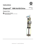
About the SynchLink Bypass Switch Block
Use the SynchLink bypass switch block in SynchLink daisy-chain configuration
where a station, or group of stations, needs to be temporarily disconnected from
the SynchLink system without physical re-configuration of the cable system. The
bypass switch block is DIN rail-mounted and is housed in a two-piece plastic
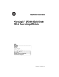
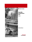
enclosure. Figure 1 identifies the components of the bypass switch block.
Figure 1 - Components of the bypass switch block
RxIN2
TxOUT2
Indicators
+24V dc
(pin 4)
+24V dc
Common (pin 3)
+24V dc Digital
Input (pin 2)
+24V dc
Common Digital
Input (pin 1)
TxOUT1
RxIN1
Din Rail Lock Tab
31223-M
The bypass switch block has two modes of operation, pass-through and bypass.
The operational mode is determined by the state of the 24V dc digital input that is
driven by the local SynchLink station.
The pass-through mode is entered when the digital input is ON. In this mode,
optical signals from the upstream station are received at the receiver port RxIN1
and retransmitted to the local station via the transmitter port TxOUT2. Optical
signals generated by the local station are received at the receiver port RxIN2 and
retransmitted to the downstream station via the transmitter port TxOUT1. There is
no re-timing or signal regeneration in this mode.
The bypass mode is entered when the digital input is OFF. In this mode, signals
received from the upstream station at the port RxIN1 are converted to electrical
signals, re-timed, and retransmitted to the downstream station via the port TxOUT1.
The bypass switch block has no capabilities to detect or correct communication
error conditions that may exist during the course of pass-through or bypass
operation. The bypass switch block has no ability to report any abnormal
conditions to the local station.
Publication 1751-IN003B-EN-P - September 2001
SynchLink Bypass Switch Block
5
Prevent Electrostatic Discharge
ATTENTION
!
This equipment is sensitive to electrostatic discharge, which
can cause internal damage and affect normal operation.
Follow these guidelines when you handle this equipment:
•
•
•
•
•
•
Touch a grounded object to discharge potential static.
Wear an approved grounding wriststrap.
Do not touch connectors or pins on component boards.
Do not touch circuit components inside the equipment.
If available, use a static-safe workstation.
When not in use, store the equipment in appropriate
static-safe packaging.
Installing the Bypass Switch Block
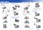
To install the switch block on the DIN rail:
1. Position the switch block on the 35×7.5mm DIN rail (Allen-Bradley catalog
number 199-DRI) at a 30° angle.
31203a-M
Publication 1751-IN003B-EN-P - September 2001
6
SynchLink Bypass Switch Block
2. Hook the lip of on the rear of the switch block onto the top of the DIN rail
and rotate the switch block onto the rail.
31203b-M
3. Press the bypass switch block down to the DIN rail until flush.
The locking tab should snap into position and lock the switch block to the
DIN rail. If the tab does not snap into position, follow step 4. If the tab does
snap into position, proceed to step 5.
31203c-M
Publication 1751-IN003B-EN-P - September 2001
SynchLink Bypass Switch Block
4. Use a
block
block
block
7
screwdriver to move the locking tab down while you press the switch
flush onto the DIN rail. Release the locking tab to lock the switch
into place. If necessary, push up on the locking tab to lock the switch
into place.
5. Use DIN rail end anchors to secure the switch block. (Allen-Bradley catalog
number 1492-EAH35)
ATTENTION
Be certain that you secure the bypass switch block with
DIN rail anchors. Failure to do so may result in loss of
communication and/or damage to switch block.
!
IMPORTANT
If you exceed the switch block’s power limit, you may
cause damage to the bypass switch block.
6. Connect the switch wiring as shown in Wiring the Bypass Switch Block
Block.
Publication 1751-IN003B-EN-P - September 2001
8
SynchLink Bypass Switch Block
Wiring the Bypass Switch Block
ATTENTION
Do not look directly into the fiber ports or fiber cable. Light
levels may cause damage to eyesight. The bypass switch block
is a Class 1 LED product.
!
To wire the bypass switch block and connect power:
1. Connect pre-terminated fiber optic cables as shown.
Connect
To
RxIN1
Upstream station transmitter
TxOUT1
Downstrean station receiver
RxIN2
Local station transmitter
TxOUT2
Local station receiver
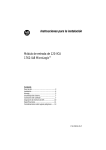
2. Pre-wire the removable connector plug as shown on the switch block label
or below.
Connect
To pin
+24V dc Power
4
24V dc Common
3
+24V dc Digital Input
2
24V dc Common Digital Input
1
IMPORTANT
Pin 1 Pin 2 Pin 3 Pin 4
Power Supply and Digital
Input Connect (front view)
31248-M
Do not connect 24V dc Common to Chassis Ground.
3. Insert the removable connector plug into the mating connector receptacle on
the switch block.
Pin 1 Pin 2
Pin 3
Pin 4
31249b-M
Connector receptacle on switch (front view)
Publication 1751-IN003B-EN-P - September 2001
SynchLink Bypass Switch Block
9
4. Screw the removable connector to the switch block with the left and right
mounting screws.
IMPORTANT
Make sure the switch block is attached and secured
prior to applying power to the switch block. Failure to
do so may cause damage to the switch block.
Indicators
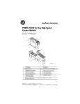
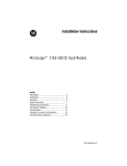
Figure 2 identifies the status indicators on the switch block.
Figure 2 - Status indicators
POWER ON
TxOUT
RxIN2
31224-M
BYPASS ON
TxOUT2
RxIN1
Publication 1751-IN003B-EN-P - September 2001
10
SynchLink Bypass Switch Block
Status Indicators
Indicator
When LED is ON
Power ON
24V dc power is applied to the switch block
Bypass ON
block is in the Bypass mode
RxIN1
optical signals are received from the upstream station
TxOUT1
optical signals are transmitted to the downstream station
RxIN2
optical signals are received from the local station
TxOUT2
optical signals are transmitted to the local station
Mounting Dimensions
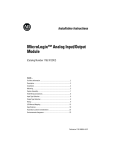
Figure 3 provides mounting dimensions for the switch block.
Figure 3 - Mounting dimensions
3.94 in.
(100 mm)
2.76 in.
(70.1 mm)
3.6 in.
(91.4 mm)
4.12 in.
(105 mm)
31234-M
Publication 1751-IN003B-EN-P - September 2001
SynchLink Bypass Switch Block
11
Hazardous Location
The following information applies when
operating this equipment in hazardous
locations:
Informations sur l’utilisation de cet équipement
en environnements dangereux :
Products marked “CL I, DIV 2, GP A, B, C, D” are
suitable for use in Class I Division 2 Groups A, B, C,
D, Hazardous Locations and nonhazardous locations
only. Each product is supplied with markings on the
rating nameplate indicating the hazardous location
temperature code. When combining products within
a system, the most adverse temperature code (lowest
“T” number) may be used to help determine the
overall temperature code of the system.
Combinations of equipment in your system are
subject to investigation by the local Authority Having
Jurisdiction at the time of installation.
Les produits marqués "CL I, DIV 2, GP A, B, C, D" ne
conviennent qu’à une utilisation en environnements
de Classe I Division 2 Groupes A, B, C, D dangereux
et non dangereux. Chaque produit est livré avec des
marquages sur sa plaque d’identification qui
indiquent le code de température pour les
environnements dangereux. Lorsque plusieurs
produits sont combinés dans un système, le code de
température le plus défavorable (code de
température le plus faible) peut être utilisé pour
déterminer le code de température global du
système. Les combinaisons d’équipements dans le
système sont sujettes à inspection par les autorités
locales qualifiées au moment de l’installation.
WARNING
!
EXPLOSION HAZARD
• Do not disconnect
equipment unless
power has been
removed or the area is
known to be
nonhazardous.
• Do not disconnect
connections to this
equipment unless
power has been
removed or the area is
known to be
nonhazardous. Secure
any external
connections that mate
to this equipment by
using screws, sliding
latches, threaded
connectors, or other
means provided with
this product.
• Substitution of
components may impair
suitability for Class I,
Division 2.
• If this product contains
batteries, they must
only be changed in an
area known to be
nonhazardous.
AVERTISSEMENT
!
RISQUE D’EXPLOSION
• Couper le courant ou
s’assurer que
l’environnement est
classé non dangereux
avant de débrancher
l'équipement.
• Couper le courant ou
s'assurer que
l’environnement est
classé non dangereux
avant de débrancher les
connecteurs. Fixer tous
les connecteurs
externes reliés à cet
équipement à l'aide de
vis, loquets coulissants,
connecteurs filetés ou
autres moyens fournis
avec ce produit.
• La substitution de
composants peut rendre
cet équipement
inadapté à une
utilisation en
environnement de
Classe I, Division 2.
• S’assurer que
l’environnement est
classé non dangereux
avant de changer les
piles.
Publication 1751-IN003B-EN-P - September 2001
12
SynchLink Bypass Switch Block
Rockwell Automation Support
Rockwell Automation offers support services worldwide, with over 75 sales/support
offices, over 500 authorized distributors, and 260 authorized systems integrators
located throughout the United States alone, plus Rockwell Automation
representatives in every major country around the world. Contact your local
Rockwell Automation representative for:
•
•
•
•
sales and order support
product technical training
warranty support
support service agreements
Obtain Pre-Sales Product Support
If you need to contact Rockwell Automation for pre-sales product support, try one
of the following methods:
• Call your local Rockwell Automation representative
• Network Pre-sales support line, 1.440.646.3638 (3NET)
• Pre-Sales e-mail, [email protected]
Obtain Technical Product Support
If you need to contact Rockwell Automation for technical assistance, try one of the
following methods:
• Call your local Rockwell Automation representative
• Post-Sales Technical Support:
– United States/Canada: 1.440.646.5800
– Outside the United States/Canada use: http://www.ab.com, click on
Product Support (http://support.automation.rockwell.com), under
Support Centers, click on Contact Information to find phone number for
your country
• Fax Back system, 1.440.646.5436 (requires a touch-tone telephone)
• Web Links http://www.ab.com — as a registered member, open to
http://www.ab.com/mem/technotes/techmain.html
Publication 1751-IN003B-EN-P - September 2001
SynchLink Bypass Switch Block
13
Specifications
Power Supply
To comply with CE Low Voltage directives, you must use a
Safety Extra Low Voltage (SELV) or a Protected Extra Low
Voltage (PELV) power supply to power this bypass switch block.
Use a NEC/CEC Class 2 power supply in order to comply with
UL and CSA requirements.
Power Supply Rating
0.1A @ 24V dc nominal
Power Supply Range
20V dc to 30V dc
A regulated power supply is recommended.
Communication Rate
5M bit/s
Terminal Block Torque Requirements
5-7 inch-pounds maximum
Environmental Conditions
Operating Temperature
0 to 60°C (32 to 140°F)(1)
Storage Temperature
–40 to 85°C (–40 to 185°F)(2)
Relative Humidity
5 to 95% non-condensing(3)
Vibration
5g @ 10-500Hz(4)
Shock
Operating 30g(5)
Non-operating 50g
Emissions
Group 1, Class A(6)
ESD Immunity
6kV contact discharges(7)
8kV air discharges
Radiated RF Immunity
10V/m with 1kHz sine-wave 80%AM from 30MHz to 1000MHz(8)
10V/m with 200Hz 50% Pulse 100%AM at 900Mhz
EFT/B Immunity
±2kV at 5kHz on power ports(9)
±2kV at 5kHz on signal ports
Surge Transient Immunity
+2kV line-earth (CM) on shielded ports(10)
Conducted RF Immunity
10Vrms with 1kHz sine-wave 80%AM from 150kHz to 80MHz(11)
Enclosure Type Ratings
8.0 pt
Fiber Optic Cable
Fiber Type
200/230 micron HCS (Hard Clad Silica)
Fiber Termination Type
Versalink V-System
Assemblies
Cable assemblies can be ordered from Allen-Bradley, catalog
number 1403-CFxxx (xxx = length in meters); or from Lucent
Technologies, Specialty Fiber Technologies division.
Maximum Length
300 meters
Minimum Length
1 meter
Publication 1751-IN003B-EN-P - September 2001
14
SynchLink Bypass Switch Block
Power Conductors
Wire Size
12 gauge maximum, 24 gauge minimum (#12 AWG to 24
AWG), stranded
Category
2(12)
Maximum Length
3 meters
Digital Input
isolated, sinking
ON-State Voltage
12V dc minimum
24V dc nominal
30V dc maximum
ON-State Current
12.0mA nominal at 24V dc
OFF-State Voltage
8.0V dc maximum
Isolation Voltage
Tested to withstand 850 Vdc for 60 seconds
Conductors
use shielded two-conductor cable
Wire Size
12 gauge maximum
24 gauge minimum
(#12 AWG to #24 AWG)(13)
Category
2(12)
Maximum Length
10 meters
Certifications
(when product is marked)
UL
CSA
CE(14)
C-Tick
(1)
(2)
(3)
(4)
(5)
(6)
(7)
(8)
(9)
(10)
(11)
(12)
UL Listed Industrial Control Equipment
CSA Certified Process Control Equipment for Class
I, Division 2 Group A,B,C,D Hazardous Locations
European Union 89/336/EEC EMC Directive,
compliant with:
EN 50081-2; Industrial Emissions
EN 50082-2; Industrial Immunity
EN 61326; Meas./Control/Lab., Industrial
Requirements
EN 61000-6-2; Industrial Immunity
Australian Radiocommunications Act, compliant
with:
AS/NZS 2064; Industrial Emissions
IEC 60068-2-1 (Test Ad, Operating Cold), IEC 60068-2-2 (Test Bd, Operating Dry Heat), IEC 60068-2-14 (Test Nb, Operating
Thermal Shock)
IEC 60068-2-1 (Test Ab, Un-packaged Non-operating Cold), IEC 60068-2-2 (Test Bc, Un-packaged Non-operating Dry Heat),
IEC 60068-2-14 (Test Na, Un-packaged Non-operating Thermal Shock)
IEC 60068-2-30 (Test Db, Un-packaged Non-operating Damp Heat)
IEC60068-2-6 (Test Fc, Operating)
IEC60068-2-27:1987, Test Ea (Unpackaged shock, ES#002)
CISPR 11
IEC 61000-4-2
IEC 61000-4-3
IEC 61000-4-4
IEC 61000-4-5
IEC 61000-4-6
You use this category information for planning conductor routing as described in publication 1770-4.1, “Industrial
Automation Wiring and Grounding Guidelines.”
Publication 1751-IN003B-EN-P - September 2001
SynchLink Bypass Switch Block
(13)
(14)
15
Shielded cable required.
See Product Certification link at www.ab.com for Declarations of Conformity, Certificates, and other certification details.
Allen-Bradley, ControlLogix, PowerFlex 700s, and SynchLink are trademarks of Rockwell Automation.
ControlNet is a trademark of ControlNet International.
Publication 1751-IN003B-EN-P - September 2001
Publication 1751-IN003B-EN-P - September 2001
Supersedes Publication 1751-IN003A-EN-P - March 2001
PN 957626-14
Copyright © 2001 Rockwell Automation. All rights reserved. Printed in the U.S.A.