1
3.Attach the back box of type 1 camera /base plate
of type2 camera to the ceiling and secure them
with supplied self-tapping screws.
4.Route the cables through the cable hole.
5.Align the camera with the back box/base plate,
and tighten the set screws to secure the camera
with the back box/base plate.
Type I I :
Type I:
Type I I :
Type I:
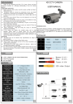
Figure 2-6 Fix the Camera to the Mount
6. Repeat steps 6-8 of the Ceiling Mounting section
to complete the installation.
2.3 In-ceiling Mounting with
Gang Box
Figure 2-3 Fix the Camera to the Ceiling
6. Connect the corresponding cables.
7. Adjust the camera according to the figure below
to get an optimum angle.
8. Fit the black liner on the camera and tighten the
screws on the bubble of type 1 camera or rotate the
bubble of type 2 camera to complete.
Only the type 1 camera supports in-ceiling
mounting with gang box.
1.Repeat steps 2-4 of the In-ceiling Mounting
section to secure the in-ceiling mount (supplied)
to the gang box.
3.1 VIDEO.OUT
PAL or NTSC is selectable .
3.2 LANGUAGE
English, Japanese, CHN1, CHN2, Korean, German,
French, Italian, Spanish, Polish, etc., are selectable.
3.3SETUP
3.3.1 SCENE
You can select indoor, outdoor, indoor 1 and low
-light as the working environments.
3.3.2 LENS
The camera is equipped with a fixed lens.
3.3.3 EXPOSURE
SHUTTER: AUTO,1/25, 1/50, FLK, 1/200, 1/400,
1/1k, 1/2k, 1/5k, 1/10k, 1/50k, x2, x4, x6, x8, x10,
and x15 are selectable.
AGC : You can set the AGC value from 0 to 15.
SENS-UP : You can set the SENS-UP to OFF or AUTO.
BRIGHTNESS : You can set the brightness value
from 1 to 100.
DEFOG : You can set the defog function as ON to
enable the function. Position, size, and the defog
gradation are configurable.
EXPOSURE
Figure 2-7 Install the Mount
2.Route and connect the corresponding cables.
3.Align the camera with the gang box, and tighten
the screws to secure the camera with the gang box..
Type I I :
Type I:
0°~90°
T Direction
0°~90°
1. SHUTTER
2. AGC
3. SENS-UP
4. BRIGHTNESS
5. DEFOG
6. BACKLIGHT
7. RETURN
AUTO
OFF
-----|------ 40
OFF
OFF
RET
T Direction
R Direction
0°~355°
P Direction
0°~355°
0°~340°
0°~ R
355
°
Direction
Figure 3-2 Exposure
P Direction
Figure 2-4 Zoom and Focus Adjustment
2.2 In-ceiling Mounting
You need to purchase an in-ceiling mount separately
if you adopt in-celling mounting.
Steps:
Figure 2-8 Fix the Camera to the Gang Box
4. Repeat steps 6-8 of the Ceiling Mounting section
to complete the installation.
1.Drill the screw holes and the cable hole in the
ceiling according to the supplied drill template.
2.Screw the bolts through the mount by aligning
with the 2 bolt holes. Fit the toggles onto the bolts.
3.Push the two toggle bolts through the two screw
holes on the ceiling. Rotate the bolt till the toggle
holds the ceiling tightly.
3 Menu Operation
Menu
VIDEO.
OUT
SETUP
LAUGUAGE
SCENE
LENS
EXPOSURE
BACKLIGHT
WB
DAY&NIGHT
NR
SPECIAL
ADJUST
RESET
INDOOR
MANUAL
SHUTTER
BLC
ATW
COLOR
2D NR
CAM
TITLE
SHARPNESS
EXIT
OUTDOOR
AGC
HSBLC
AWC-SET
B/W
3D NR
D-EFFECT
MONITOR
INDOOR1
SENS-UP
INDOOR
EXT
MOTION
LSC
LOWLIGHT
BRIGHTNESS
OUTDOOR
D-WDR
MANUAL
DEFOG
PRIVACY
DEFECT
VERSION
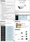
Figure 3-1 Main Menu
Figure 2-5 Install the Mount
4.Route and connect the corresponding cables.
5.Fix the camera to the in-ceiling mount with the
supplied screws.
You can call the menu and adjust the camera
parameters with a coaxial camera controller
(purchase separately). You can also call the menu
with supported TVI DVR.
HSBLC
1. SELECT
AREA 1
2. DISPLAY
ON 8
3. LEVEL
---|------ 40
4. MODE
ALL DAY
5. BLACK MASK
ON
6. DEFAULT
8
7. RETURN
RET
Figure 3-3 HSBLC
3.3.4 Backlight
Backlight Compensation (BLC):
-GAIN: Set the gain of BLC as High, Middle, or Low.
-AREA: Press the up/down/left/right button to
define the BLC position and size. Select RET or
AGAIN to go back the BLC menu or re-define the
BLC area.
-Default: Restore the BLC settings to the default.
HSBLC: Select an HSBLC area. Set the DISPLAY
status as ON. Press the up/down/left/right button
to define the area position and size. Set the HSBLC
LEVEL from 0 to 100. Select ALL DAY or Night for the
HSBLC mode. Set the BLACK MASK status as ON or
OFF.
3.3.5 White Balance (WB)
INDOOR, OUTDOOR, MANUAL, ATW (Auto-tracking
White Balance), AWC→SET are selectable.
3.3.6 Day & Night
Color, B/W, and EXT are selectable for DAY and
NIGHT switches.
3.3.7 NR
2D NR : You can set 2D NR status as ON or OFF.
3D NR : Set the Smart NR status as ON and adjust
the 3D smart NR sensitivity ranges from 0 to 100.
Set the 3D NR LEVEL ranges from 0 to 100. Set the
START. AGC level as the threshold to enable AGC,
and set the END. AGC level as the threshold to
disable AGC.
3D NR
ON8
------|--8 0
-|--------10
-|--------10
RET
1. 2DNR
OFF
2. 3DNR
ON 8
3. RETURN RET
1. SMART NR
2. LEVEL
3. START. AGC
4. END. AGC
5. RETURN
Figure 3-4 NR
Figure 3-5 3D NR
2D&3D NR
3.3.8 SPECIAL
Camera Title: Edit the camera title on this section.
D-effect:
-FREEZE: Set the freeze function as ON or OFF.
-MIRROR: OFF, MIRROR, V-FLIP, and ROTATE are
selectable for mirror.
-D-ZOOM: Define the zoom area by configuring
the position from PAN & TILT.
-SMART D-ZOOM: The D-Zoom area, sensitivity
and time are configurable.
-NEG.IMAGE: Set the NEG IMAGE as ON or OFF.
SPECIAL
1. CAM TITLE
2. D-DFFECT
3. MOTION
4. PRIVACY
5. LANGUAGE
6. DEFECT
7. VERSION
8. RETURN
MOTION
ON 8
8
OFF
OFF
ENG 8
8
130722
RET
1. SELECT
AREA 1
2. DISPLAY
ON8
3. SENSITIVITY ----|---- 30
4. MOTION VIEW ON
5. DEFAULT
8
6. RETURN
RET
Figure 3-6 Special Figure 3-7 Motion Detection
Motion: Select a MOTION area. Set the DISPLAY
status as ON or OFF. Press the up/down/left/right
button to define the position and size of the area.
Set the SENSITIVITY from 0 to 60. Set the MOTION
VIEW status as ON or OFF.
Privacy: Select a PRIVACY area. Set the DISPLAY
status as INV, MOSAIC, COLOR or OFF. Press the
up/down/left/right button to define the position
and size of the area.
Defect: LIVE DPC, STATIC DPC and Black DPC are
adjustable in this section.
Version : You can check the software version of the
device.
PRIVACY
ADJUST
1. SELECT
2. DISPLAY
3. COLOR
4. TRANS.
5. DEFAULT
6. RETURN
AREA 1
MOSAIC 8
10
1
8
RET
Figure 3-8 Privacy Mask
1. SHARPNESS
2. MONITOR
3. LSC
4. VIDEO. OUT
5. RETURN
--------|15
LCD8
OFF
PAL
RET
Figure 3-9 Adjust
3.3.9 ADJUST
Sharpness : Adjust the sharpness from 0 to 15.
Monitor : Monitor CRT, and Monitor LCD are
selectable.
LSC : Set the LSC status as ON or OFF.
3.3.10 RESET
Reset all the settings to the default.
3.3.11 EXIT
Press OK to exit the menu.