1
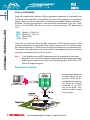
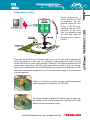
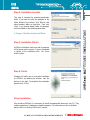
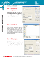
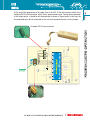
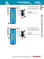
CONTENTS
AVRprog Programmer
AVRflashSoftware Installation
AVRflash Software
Keyboard Shortcuts and Command Line Parameters
Programmer’s Operation
AVRprog Programmer Connection Schematics
4
6
8
9
10
13
4
AVRprog PROGRAMMER
AVRflash PROGRAMMER
Along with complementary software, AVRprog programmer represents an irreplaceable tool
for all those working with AVR microcontrollers. By means of this programmer, it is possible to
program almost any AVR microcontroller, including those embedded (soldered) in printed circuit board. The AVRprog programmer is connected to the microcontroller via six lines. Two of
them are +5V and GND, while others are used for signal transmission (SPI protocol) and
reset:
MISO
MOSI
SCK
mRST
(Master In - Slave Out)
(Master Out - Slave In)
(Serial Clock)
(Reset)
These lines are contained within a flat cable ending with an IDC10 female connector. When
creating a target device, the appropriate 10-pin male connector with 2.54 mm space between
pins should be placed on it. Connector pins should be connected to the microcontroller pins.
Their position varies depending on the microcontroller’s type and package. Exact connection
schematics are provided at the end of this manual.
Note:
If your target device uses MCU programming pins for the operation of some other
peripherals, then it should be enabled to these peripherals to be disconnected during
programming. Jumpers are commonly used for disconnecting the MISO, MOSI, SCK
and mRST programming pins.
Programmer is inactive
During normal operation of
the target device, the programmer should be disconnected, while peripherals should be normally
connected to the MCU
pins as per project. Connection is made by means
of four jumpers.
Programmer is active
During programming a
device with built-in AVR
microcontroller, the programmer should be connected to the MCU programming pins via IDC10
connector. At the same
time, any peripheral using
the same pins should be
disconnected by means of
jumpers.
If the target board has its own 5V power supply, then it can be also used for powering the
AVRprog programmer. In that case, it is necessary to open programmer plastic case and
remove the jumper for power supply selection. Otherwise, if the target board does not have
its own power supply source, then the jumper should not be removed. In that case, the programmer, the microcontroller and the whole electronics are powered via programmer’s USB
cable which connects the programmer to a PC. Any other power supply on the target board
must be suspended.
This picture illustrates the position of jumper when the target board
and the programmer are powered via USB cable.
This picture illustrates the programmer with no jumper for power supply selection. In this case the programmer is powered by the target
board which has its own power supply.
AVRflash PROGRAMMER
5
6
AVRflash PROGRAMMER SOFTWARE INSTALLATION
In order to enable programming microcontrollers using AVRprog programmer, it is necessary
to install the AVRflash programmer program (“AVRflash”) on your PC. The same program is
used for programming AVR microcontrollers using EasyAVR development board.
AVRflash SOFTWARE INSTALLATION
Step 1: Start installation
Insert the product CD into a PC drive. A list with all
MikroElektronika’s products appears. Click the setup
icon to start software installation:
AVRflash software for Windows
AVRflash_setup.exe may be also downloaded
free of charge from our web site. Then you have
to start the installation from your hard drive. A
welcome window appears. Click ‘Next’.
Step 2: Licence Agreement
Prior to start the installation, please review the
License terms. If you accept them, select the
option ‘I accept the terms in the License Agreement’ and click ‘Next’ afterwards.
Step 3: Choose Components
To make it as simple as possible, this step does
not requires you to choose components to install.
Click ‘Next’ to continue.
Note:
Make sure that AVRprog programmer
is not connected to the PC during soft
ware installation.
This step is intended for choosing destination
folder. If you want to install the program to the
folder different from default, click ‘Browse’ and
select another folder on hard disc. Then click
‘Next’. If you choose default folder, the program
will be installed on the following destination:
C:\Program Files\Mikroelektronika\AVRflash
Step 5: Installation Details
AVRflash installation starts here and its progress
will be shown on the screen. If you are interested
in details of the installation click the ‘Show
details’ button.
Step 6: Finish
Windows will notify you of successful installation
of AVRflash, by showing the window from the
picture on the right. To complete the installation
process click ‘Finish’.
Driver installation
After installing AVRflash, it is necessary to install the appropriate drivers on your PC. They
enable programmer’s hardware to operate properly. For information on their installation,
please refer to ‘Installing USB drivers’ manual.
7
AVRflash SOFTWARE INSTALLATION
Step 4: Installation Location
8
AVRflash SOFTWARE
AVRflash SOFTWARE
Step 1: Run AVRflash
programmer
Run AVRflash from your PC. Click the
Device option and select the appropriate
microcontroller to program. AVRflash will
automatically set parameters to work
with the specified microcontroller.
Step 2: Load HEX file
Click the ‘Load’ option which opens the
window shown on picture on the right.
Select the appropriate executable file (having extension .HEX in its name) and click
the Open option. AVRflash will do all necessary settings on the basis of control bits
stored in the HEX file.
Step 3: Write program
Click the Write option in the up-right corner of
the working window to start programming the
microcontroller. The progress of programming will be shown in the right bottom corner
of the working window.
Keyboard Shortcuts
Command Line
Erase
Write
Verify
Read
Change MCU
Save
Open (Load)
Reload
Alternatively, you can activate the AVRflash from the command line. It also
enables you to use AVRflash from some other software, compiler etc. Here
is the list with the command line parameters:
-w
-v
-e
-r
-p
-f
Example 1
Alt-E
Alt-W
Alt-V
Alt-R
Alt-D
Ctrl-S
Ctrl-O
Ctrl-R
Write to AVR
Verify
Erase AVR
Read from AVR
AVR name (for example ATMEGA16, ATMEGA8535s...)
File name (must be enclosed with " “)
avrprog.exe -w -pATMEGA16 -v -f"C:\somefile.hex"
This command programs the AVR using C:\somefile.hex and verifies
written data.
Example 2
avrprog.exe -r -pATMEGA16
This command reads the AVR contents.
Example 3
avrprog.exe -e -pATMEGA16
This command erases the AVR.
9
KEYBOARD SHORTCUTS
KEYBOARD SHORTCUTS AND COMMAND LINE PARAMETERS
10
PROGRAMMER’S OPERATION
PROGRAMMER’S OPERATION
Programming an AVR microcontroller is performed by using signals mRST, MISO, MOSI and
SCK from the AVRprog programmer. They are brought to the appropriate reset and SPI communication pins. In order to enable programming to run without errors, make sure that these
pins are not connected to other electronic components. Otherwise, during normal operation,
these pins must be connected to other components as per project.
Since the microcontroller is soldered on the printed circuit board (with no use of socket), it is
necessary to enable these pins to be connected to/disconnected from the rest of electronics
by using jumpers. Because of that, do not forget to embed 4 jumpers when designing a
device.
At the end of the programmer’s flat cable, there is an IDC 10 female connector which fits to
on-board IDC10 male connector with 2.54mm space between pins. During normal operation
of the target device, it should be left disconnected as shown in figure below. In that way, the
microcontroller pins will be connected to the rest of on-board electronics via four jumpers.
11
PROGRAMMER’S OPERATION
On-board IDC10 male connector
PROGRAMMER’S OPERATION
12
During programming, the IDC 10 male connector is used to bring signal from the programmer.
To enable it, it is necessary to remove jumpers and plug the programmer’s connector into the
on-board connector.
Connection between on-board
male IDC 10 connector and 8-pin
AVR microcontrollers such as:
ATtiny15
Connection between on-board
male IDC 10 connector and 8-pin
AVR microcontrollers such as:
AT90S2323, 2343...
ATtiny12, 13, 25, 45, 85...
Connection between on-board
male IDC 10 connector and 14pin AVR microcontrollers such as:
ATtiny24, 44, 84...
13
CONNECTION SCHEMATICS
AVRprogrammer CONNECTION SCHEMATICS
14
Connection between on-board
male IDC 10 connector and 20-pin
AVR microcontrollers such as:
CONNECTION SCHEMATICS
90S1200, 2313...
ATtiny2312...
Connection between on-board
male IDC 10 connector and 20-pin
AVR microcontrollers such as:
ATtiny26...
Connection between on-board
male IDC 10 connector and 28-pin
AVR microcontrollers such as:
AT90S4433...
ATmega8, 48, 88, 168...
Connection between on-board
male IDC 10 connector and 40-pin
AVR microcontrollers such as:
15
Connection between on-board
male IDC 10 connector and 40-pin
AVR microcontrollers such as:
AT90S8535...
ATmega16, 32, 163, 323, 8535
CONNECTION SCHEMATICS
AT90S8515...
ATmega161, 162, 8515...
16
CONNECTION SCHEMATICS
Connection between on-board
male IDC 10 connector and
64-pin AVR microcontrollers
such as:
ATmega103, 128, 1280, 128,
165, 169, 2560, 2561, 325,
3250, 329, 3290, 64, 640,
644, 645, 6450, 649, 6490...
After programming, the programmer’s IDC10 female
connector
must
be
unplugged and jumpers
must be put on. It enables
the MCLR, MISO, MOSI and
SCK pins to be connected to
the rest of on board electronics, which further enables
device to operate normally
without being affected by the
AVRprog programmer. If
needed, the jumpers can be
removed and AVRprog can
be reconnected in order to
reprogram the chip.
Note: Target board must not have electrolytic capacitors between the microcontroller pins and
embedded IDC10 male connector since the power supply voltage is controlled by the
AVRprog programmer.