1
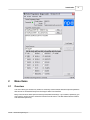
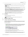
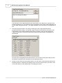
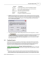
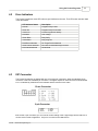
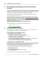
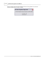
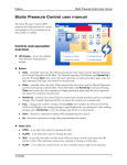
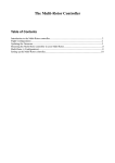
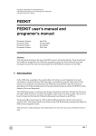
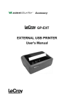
NPE Pocket Programmer User Manual
for the Standard and USB models
Copyright 2006 - 2010 North Pole Engineering, Inc.
NPE Pocket Programmer User Manual
Copyright 2006 - 2010 NPE, Inc.
All rights reserved. No parts of this work may be reproduced in any form or by any means - graphic, electronic, or
mechanical, including photocopying, recording, taping, or information storage and retrieval systems - without the
written permission of the publisher.
Products that are referred to in this document may be either trademarks and/or registered trademarks of the
respective owners. The publisher and the author make no claim to these trademarks.
While every precaution has been taken in the preparation of this document, the publisher and the author assume no
responsibility for errors or omissions, or for damages resulting from the use of information contained in this document
or from the use of programs and source code that may accompany it. In no event shall the publisher and the author be
liable for any loss of profit or any other commercial damage caused or alleged to have been caused directly or
indirectly by this document.
Printed: Nov. 30, 2006 in Minneapolis, MN.
Revised: May 10, 2010
Publisher
North Pole Engineering, Inc.
Technical Editors
Joe Tretter, Steve Hidem
Contact Information
North Pole Engineering, Inc.
221 1st St. N.
Suite 310
Mpls. Mn. 55401
Website: www.npe-inc.com
Email: [email protected]
Introduction
1
Introduction
1.1
Welcome
3
Thank You for purchasing the NPE Pocket Progarmmer
Please check the NPE Website Product Support
section for program updates and information on this
and other NPE products.
When you buy an NPE product registering your
purchase will give you full access to the support pages
for NPE products.
About this Help File
This help file covers both the NPE101-A and the NPE201-A Pocket Programmers. The NPE101-A is
used with the NPE Desktop Programmer to load target images into the Pocket Programmers. The NPE
201-A is the USB version of the Pocket Programmer and does not require a Desktop Programmer to
load target images; it connects directly to the USB port on your PC.
Extra information on a topic is highlighted with the FYI (For Your Information) heading. Read this
information to get a more in depth understanding of the current topic.
The Good Practices headline shows the correct way to accomplish a task. Following these steps
assures best operation of the Pocket Programmer.
Help File Version 4.2
© 2010 ... North Pole Engineering, Inc.
4
1.1.1
NPE Pocket Programmer User Manual
Update History
Version
4.2
4.1
1.2
Description
Modified Advanced Menu Help.
The section incorrectly stated that the advanced menu is only available for NPE201.
Some items are available to the NPE101 pocket programmer as well.
Added New Advanced Menu Item.
The advanced menu now has an item to allow the user to add a new chip support DLL.
Updated section Using the Pocket Programmer | Programming a Target.
This section was rewritten because it had information from the NPE101 rev 1 device
that is no longer correct.
Modified Firmware Section of Help File.
Created a separate file that contains the section information on updating the Pocket
Programmer Firmware. This is only a structural change and did not affect content.
Getting Started
The NPE Pocket Programmer comes in two models; the NPE101-A, which requires the NPE Desktop
Programmer to load target image files and settings. And the NPE201-A, which is the USB version of
the Pocket Programmer and connects directly to the USB port on your PC.
Both Pocket Programmers use the Image Loader application to load the target image and settings into
the Pocket Programmer. The Image Loader application is smart enough to detect the Pocket
Programmer being used and connect to it automatically.
FYI - Do not connect both types of Pocket Programmers to a single PC at the same time. This will
cause erratic behavior!
Image Loader Application
Click on the different regions of the Image Loader User Interface shown below to get a quick
overview of the different functional areas of the application.
© 2010 ... North Pole Engineering, Inc.
Introduction
2
Menu Items
2.1
Overview
5
The menu items give access to a number of commonly used functions and some special operations
that can not be accessed directly from the Image Loader User Interface.
Many of the functions have speed access keys associated with them. If you know the speed key you
don't need to use the mouse to select the function from the menu. The table below lists the function
and associated speed key.
© 2010 ... North Pole Engineering, Inc.
6
NPE Pocket Programmer User Manual
Menu Function
Speed Key
File | Select Target FLASH
<ctrl>T
File | Select Target EEPROM
<ctrl>E
File | Load Target Image
None
File | Exit
<ctrl>X
Project | Load Project
<ctrl>O
Project | Save Project
<ctrl>S
Advanced | Add Chip
None
Advanced | Save Image to Hex File
None
Advanced | Set SPI Clock
None
Advanced | Update Firmware
None
Help | Help Manual
F1
Help | About
<ctrl>A
FYI - <ctrl>T means hold down the Control Key on the keyboard while simultaneously pressing the 'T'
key. NOTE: the case of the letter does not matter.
2.2
File Menu
The File Menu contains four functions that are explained below.
Select Target FLASH - This selection opens a file dialog box and allows you to select the FLASH
file to be loaded into the Pocket Programmer. This selection has the same effect as using the
FLASH Files... button on the user interface.
Select Target EEPROM - This selection opens a file dialog box and allows you to select the
EEPROM file to be loaded into the Pocket Programmer. This selection has the same effect as using
the EEPROM Files... button on the user interface.
Load Target Image - This selection is grayed out if a minimum of Target information has not been
entered. Once the minimum required selections have been made this selection, along with the Load
Image button on the user interface, become active. When selected the Target information that has
been entered is transferred to the Pocket Programmer. After successfully completing this step, you
are ready to disconnect the Pocket Programmer and program some target boards!
Exit - Closes the application.
2.3
Projects Menu
Projects are a powerful way to save and load a particular set of Target selections, for more information
see Creating Projects. This menu has two selections, described below.
Load Project - Loads a previously saved project.
Save Project - Saves the current selections in a project file. The project file can be loaded at a later
date and will duplicate the project selections and settings as they were saved.
2.4
Advanced Menu
The Advanced Menu allows you to add support for new Atmel AVR devices as NPE releases the
support files. You can also set the SPI clock programming speed, save the stored image to a hex file,
© 2010 ... North Pole Engineering, Inc.
Menu Items
7
or update the Pocket Programmer firmware. Some options are only available when the NPE201-A USB
Pocket Programmer is attached.
Add Chip - Allows you to add support for new Atmel AVR processors. Chip support from NPE is
provided as a DLL file.
Save Image to HEX File - This option allows you to save the contents of the flash and/or EEPROM
image stored in the Pocket Programmer to Intel hex format files on your PC.
Set SPI Clock - (NPE201 Only) This option allows you to set the SPI clock frequency that the target
MCU is programmed at. WARNING! Setting the incorrect SPI clock rate will cause target
programming to fail. The SPI clock rate should be 1/4 the target MCU clock rate or less. The default
clock rate is 115.2 kHz, which will program any target MCU that has the clock option set to the
internal RC oscillator. Higher speeds are possible with other clock options since the Pocket
Programmer sets the fuse bits first before programming the flash and/or EEPROM.
Update Firmware - (NPE201 Only) This option allows you to update the Pocket Programmer
firmware. NPE provides updates to the Pocket Programmer firmware as .ENC files.
2.5
Help Menu
The Help menu has two selections, described below.
Help Manual - Open this file.
About - Opens the about dialog box, which the software vesions running on your PC.
3
Using the Image Loader
3.1
Loading a Target Image and Settings
The Image Loader application allows you to create an image of a Target system and load that image
into the Pocket Programmer. The Pocket Programmer then transfers that information to the Target
system when it is programming.
To create a Target image:
1.
Connect the Pocket Programmer to the Desktop Programmer or USB port of your computer. The
Image loader application will change the Connected LED in the Pocket Programmer Status pane
to GREEN and display the Serial Number, Version and Last Operation information when the
Pocket Programmer is found. The status pane should look something like this -
when the Pocket Programmer is ready to accept the Target Image.
2.
Select a FLASH and/or EEPROM file to be loaded into the Target processor. You only are
required to select one file type, as your application requires.
3.
Enter a description of the Target data being loaded in the Target Description box that follows the
EEPROM file box. The Target Files and Description pane should look something like this -
© 2010 ... North Pole Engineering, Inc.
8
NPE Pocket Programmer User Manual
The information in the Target Description will not be written to the Target but it is written into the
Pocket Programmer. So if you attach the Pocket Programmer to the Image Loader application you
can see what is programmed into it. The Target Description area can hold up to 128 characters of
text.
4.
Select the Target Processor! This is the processor type on the Target board that will be
programmed with this image. The selected Target Processor must match the processor on the
Target board or the Pocket Programmer will refuse to program it. Once you have selected a
Target Processor the Lock and Fuse bits that are defined for that processor are displayed, as
shown below.
Here the Atmel ATmega64 processor was selected. The Lock and Fuse bits will initially be set to
the defaults as specified in the data sheet for the selected processor.
5.
Set the Lock and Fuse bits to the desired values. You may need to consult the data sheet for the
selected processor to determine the settings for the Lock and Fuse bits. When you check a Lock
or Fuse bit it writes it to the selected state. The settings here show:
© 2010 ... North Pole Engineering, Inc.
Using the Image Loader
Checked
9
Description
LB1, LB2
Further programming of FLASH and EEPROM is disabled.
CKSEL[3:1]
Internal 1 MHz nominal frequency clock selected (default).
SUT0
6 clk + 65 ms - Slowing rising power.
BOOTSZ[1:0]
4096 words reserved for boot sector.
EESAVE
Don't erase EEPROM data.
M103C
ATmega103 compatibility mode selected.
6. Optional: Set the target SPI clock programming frequency. Make sure the fuse bits are correctly
set for the desired target processor clock speed. The SPI clock rate should be 1/4 the target MCU
clock rate or less. The default clock rate is 115.2 kHz, which will program any target MCU that has
the clock option set to the internal RC oscillator. Go to the Advanced Menu and select Set SPI
clock. The following dialog appears.
7.
At this point we are ready to load the settings and files into the Pocket Programmer. To do that
click
You will see the progress bar indicating the progress of the load process and
the Status area will display a success message. At this point you can remove the Pocket
Programmer from the Desktop Programmer or the USB. FYI - If you want to save these settings
into a project file do not remove the Pocket Programmer until you have selected the Project |
Save Project menu item.
3.2
Creating Projects
Projects are a great way for an engineer to create a specific Target Image and allow less technical
users to load a Pocket Programmer with the correct settings. Project files can be emailed or sent to
other sites where Pocket Programmers are used and will work correctly because each project file
contains all of the files and settings that make up the Target Image to be programmed.
Creating a Project is simple. First, configure the Target files and settings (see
Loading a Target Image and Settings for details). Then select Project | Save Project (or <ctrl>S) from
the menu. And finally choose a location and name for the project and click the Save button. That's all
there is to it!
FYI:
A project file is a type of zip file that contains the target FLASH and/or EEPROM image file and a
control file that describes the other settings of the user interface. Since this bundle of files contains
all the information about a Target Image programming operation, you can copy these files to other
© 2010 ... North Pole Engineering, Inc.
10
NPE Pocket Programmer User Manual
PCs that have the Image Loader application on them.
3.3
Loading Projects
Connect a Pocket Programmer to the PC running the Image Loader application. Notice the Connected
LED goes GREEN.
To load a previously saved project, go to the menu Project | Load Project or use <ctrl>O to open a
Project load dialog box. Navigate to the directory that contains the project to load and select the project
file (.ppj extension), then click the Open button.
The project file will be opened and read into the Image Loader Application. Then click the Load Image
button to load the Target Image into the Pocket Programmer.
3.4
Load Last Project
The Load Last Project button is useful for loading a number of Pocket Programmers during the same
session. The Load Last Project button becomes active when a project has been loaded from the
project menu and a new Pocket Programmer has been connected. Clicking this button starts loading
the files and settings into the Pocket Programmer as specified in the project.
4
Using the Pocket Programer
4.1
Programming a Target
The NPE Pocket Programmer is extremely easy to use. This section will step you through using the
NPE Pocket Programmer to program a target board. These steps assume you have a target image is
loaded into the Pocket Programmer.
1.
Connect the NPE Pocket Programmer to the unit to be programmed.
2.
Power up the board to be programmed. The programming LED on the Pocket Programmer
should be solid yellow, indicating that the Pocket Programmer is ready to program.
3.
Momentarily press the program button to begin programming the target unit.
The status indicator LED will blink yellow while the programming operation is active.
After programming the verify operation will take place, during verify the status indicator will
blink green.
c. Finally, after the verify operation the status indicator will show a steady green if the operation
was successful or a steady red if an error was detected.
a.
b.
© 2010 ... North Pole Engineering, Inc.
Using the Pocket Programer
4.2
11
Error Indicators
The Pocket Programmer uses LED codes to give feedback to the user. The LED codes used are listed
in the table below.
4.3
LED Indicator Status
Description
Red On
Program/Verify Failed
Green On
Program/Verify Succeeded
Yellow On
Pocket Programmer Ready
Red Blink
Low Voltage
Green Blink
Busy Verify
Yellow Blink
Busy Program
Red/Green Alternate
No Target Device Attached
Green/Yellow Alternate
No Flash or EEPROM Image Present
Red/Yellow Alternate
Not Defined
ISP Connector
The Pocket Programmer is shipped with one of two types of connectors, either the standard 10-pin
connector or the new STK500 6-pin connector. The signal outputs for each connector is shown below.
Pin 1 is indicated by a diamond on the haeader and the red wire on the cable.
10-pin Connector
6-pin Connector
1 - MISO
3 - SCK
5 - Reset
2 - VCC
4 - MOSI
6 - GND
FYI: On the 10-pin connector, pin 3 is used to control loading of the Target Image into the NPE101-A
version of the Pocket Programmer. This pin is not used on the USB version.
© 2010 ... North Pole Engineering, Inc.
12
5
NPE Pocket Programmer User Manual
Reloading/Repairing/Updating the Pocket Programmer
Firmware
The firmware (i.e. software that runs in the Pocket Programmer) in a Pocket Programmer may become
damaged by using the Desktop Programmer to load a target application. Instead of loading the target
application the Desktop Programmer overwrites the firmware of the Pocket Programmer. That is why it
is important to use the Image Loader application when loading a target application.
If you may have done this, you can still recover use of your Pocket Programmer by reloading the
firmware. This section tells you how to do this.
Depending on which Pocket Programmer you are using, there are two different ways to update the
firmware. The NPE101-A requires the Desktop Programmer and the Desktop Programmer application.
The NPE201-A only requires the Image Loader application. It is important that you use the correct
firmware file and procedure for your version of the Pocket Programmer. See the "About Pocket
Programmer Firmware.txt" file for information on which firmware file to use. If you used the standard
install the file is located in the directory at:
C:\Program Files\North Pole Engineering\Pocket Programmer\Firmware
Select the appropriate link below for the procedure to update your firmware.
Updating the NPE101-A Firmware
Updating the NPE201-A USB Firmware
5.1
Updating the NPE101-A Firmware
There are two versions of the NPE101-A Pocket Programmer. Before loading microcode into the
Pocket Programmer you must determine which version you have.
Determining the Pocket Programmer Version
1.
2.
3.
4.
Start the Desktop Programmer application.
Attach the Pocket Programmer to the Desktop Programmer.
Click 'Connect' on the Desktop Programmer application.
After the Desktop Programmer connects, check the 'Device Type' field:
a. AT90S4433 is a version 1 Pocket Programmer.
b. ATmega8 is a version 2 Pocket Programmer.
5. See the "About Pocket Programmer Firmware.txt" file for information on which firmware file to
use. If you used the standard install the file is located in the directory at:
C:\Program Files\North Pole Engineering\Pocket Programmer\Firmware
Loading the Pocket Programmer Firmware
After determining the Pocket Programmer version, leave the Desktop Programmer connected and click
the FLASH File button. Navigate to the installation directory for the Pocket Programmer and then into
the Firmware subdirectory. If you used the standard install the directory is located at:
C:\Program Files\North Pole Engineering\Pocket Programmer\Firmware.
1.
2.
3.
4.
5.
Select the appropriate firmware file for your version of the Pocket Programmer.
Clear all Fuse Bits if any exist.
Clear all Lock Bits if any exist.
Select the 'Verify after Programming' command modifier.
Click the 'Program' button.
After a successful verify your Pocket Programmer firmware load is complete.
© 2010 ... North Pole Engineering, Inc.
Reloading/Repairing/Updating the Pocket Programmer Firmware
13
Verify that the Reload was Successful
You can verify that the microcode load restored operation of your Pocket Programmer by closing the
Desktop Programmer Application and opening the Image Loader Application. If the code was
successfully loaded the Image Loader should automatically discover the attached Pocket Programmer.
5.2
Updating the NPE201-A USB Firmware
You can only update the NPE201-A firmware with the Image Loader application. NPE distributes the
NPE201-A firmware as a .ENC file. See the "About Pocket Programmer Firmware.txt" file for
information on which file to use. If you used the standard install the file is located in the directory at:
C:\Program Files\North Pole Engineering\Pocket Programmer\Firmware.
To update the firmware, click on the Advanced menu and select Update Firmware. A dialog box will
appear prompting you to select a Pocket Programmer firmware file to download.
You will then be asked if you want to update the Pocket Programmer firmware. Click OK to update or
cancel to end the update.
© 2010 ... North Pole Engineering, Inc.
14
NPE Pocket Programmer User Manual
After you click OK, there will be short wait while the firmware is being updated. You will see the
following message When the update is complete.
© 2010 ... North Pole Engineering, Inc.