1
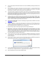
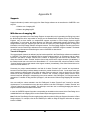
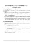
TM PD2CAEPIPE User’s Manual MANUALS/PD2CAEPIPE/man1/doc1 Issue July, 2015 Plant Design-to-CAEPIPE User’s Manual Server Version 9.xx PD2CAEPIPE User’s Manual Disclaimer Please read the following carefully: This software and this document have been developed and checked for correctness and accuracy by InfoPlant Technologies Pvt. Ltd., and SST Systems, Inc. However, no warranty, expressed or implied, is made by InfoPlant Technologies Pvt. Ltd., and SST Systems, Inc., as to the accuracy and correctness of this document or the functioning of the software and the accuracy and correctness. Users must carry out all necessary tests to assure the proper functioning of the software and the applicability of its results. PD2CAEPIPE is a trademark of SST Systems, Inc and InfoPlant Technologies Pvt. Ltd. For Technical queries, contact SST Systems, Inc. 1798 Technology Drive, Suite 236 San Jose, California 95110 USA. Tel: (408) 452-8111 Fax: (408) 452-8388 Email: [email protected] www.sstusa.com InfoPlant Technologies Pvt. Ltd. 7, Cresant Road Bangalore – 560 001 India. Tel: +91-80-40336999 Fax: +91-80-41494967 Email: [email protected] www.infoplantindia.com Table of Contents 1. Introduction ................................................................................................................... 1 1.1 How the Translator works? ....................................................................................................................... 1 2. Installing the Program .................................................................................................. 2 2.1 Operating System Requirement ............................................................................................................... 2 2.2 Installing SST License Manager ............................................................................................................... 2 2.3 Manually registering the windows service for SST License Manager ...................................................... 3 2.4 Installing the client program ...................................................................................................................... 3 2.5 Product Key Generation ........................................................................................................................... 6 2.6 Installing the Activation Key ...................................................................................................................... 7 2.7 Renewing/Re-Installing the License ......................................................................................................... 8 3.0 Limitations ................................................................................................................... 9 4. Working Procedure ..................................................................................................... 10 5.0 Reference................................................................................................................... 12 5.1 Loads ...................................................................................................................................................... 12 5.2 Pipe ......................................................................................................................................................... 12 5.3 Bend / Elbow ........................................................................................................................................... 12 5.4 Valve ....................................................................................................................................................... 12 5.5 Reducer .................................................................................................................................................. 12 5.6 Instrument ............................................................................................................................................... 12 5.7 Flange ..................................................................................................................................................... 13 5.8 Olet ......................................................................................................................................................... 13 5.9 Tee .......................................................................................................................................................... 13 5.10 Three Way Valve .................................................................................................................................. 13 5.11 Cross .................................................................................................................................................... 13 i 5.12 Four way Valve ..................................................................................................................................... 13 5.13 Material ................................................................................................................................................. 14 5.14 Support ................................................................................................................................................. 14 5.15 Thermal Anchor Movement (TAM) ....................................................................................................... 14 5.16 User defined Equipment Nozzle Allowable Loads ................................................................................ 14 5.17 Units ...................................................................................................................................................... 14 Appendix A ...................................................................................................................... 16 3D Plant Design–to–CAEPIPE Component Mapping .................................................................................. 16 Appendix B ...................................................................................................................... 17 Material ......................................................................................................................................................... 17 Material DB Modification / Creation .............................................................................................................. 17 Sample “Code” DB ........................................................................................................................................ 18 Sample “Material DB” (B315.mdb) ............................................................................................................... 18 Modification of “Config.ini” File ..................................................................................................................... 21 Appendix C ...................................................................................................................... 22 Schedule Table ............................................................................................................................................. 22 Schedule Table Creation / Modification ........................................................................................................ 22 Appendix D ...................................................................................................................... 23 Supports ....................................................................................................................................................... 23 With the use of mapping DB ......................................................................................................................... 23 Without using Mapping DB ........................................................................................................................... 24 Appendix E ...................................................................................................................... 29 Possible Restraints Types and Hangers ...................................................................................................... 29 Appendix F ...................................................................................................................... 32 Errors and Descriptions ................................................................................................................................ 32 ii 1. Introduction PLANT DESIGN-to-CAEPIPE: Plant Design-to-CAEPIPE translator program is a stand-alone program, which shall be used for transferring pipe geometry, section properties and other engineering properties from Plant Design Software to SST System Inc. Pipe Stress Analysis software CAEPIPE. The sequence of this translator operation is shown diagrammatically in Figure 1-1. Plant Design Software Plant Design Neutral File (.n) Plant Design-toCAEPIPE Translator Mapping DB (Material and Support) CAEPIPE Model Batch File (.mbf) CAEPIPE Figure 1-1 This manual describes the development done on PLANT DESIGN-to-CAEPIPE translator by InfoPlant Technologies Pvt. Ltd. It is assumed that the user is already familiar with the principles of Plant Design software piping application and the practices followed in Plant Design piping catalogue and specifications, and the user has used Plant Design software to generate the piping by using available facilities in Plant Design software. It is also assumed that the user is familiar with CAEPIPE. At this stage it is essential to know that Plant Design Software and CAEPIPE use different world coordinate systems; so, it is recommended that the user checks the CAEPIPE model once the PLANT DESIGN-to-CAEPIPE translator has generated it. 1.1 How the Translator works? The Pipe(s) or Branches modeled in Plant Design Software are initially converted to an intermediate neutral file using the Neutral file creation program. Refer .HLP file available with the product for more details. The Windows compatible executable file PD2CAEPIPE.exe reads this Plant Design Neutral File and maps it against the Material and Support mapping DB to identify the valid CAEPIPE material and support that correspond to the specified Plant Design material and support specification. This executable finally generates the Model Batch File (*.mbf), which can be imported into CAEPIPE to create model file (*.mod) that can be opened and viewed in CAEPIPE. Refer Appendix B for more details on Material Property. 1 2. Installing the Program Before installing the SST License Manager and the Client product on any of your computer, please make sure the computer meets the following requirement listed below. Note: If you are using the old version of SST License Manager (i.e., earlier than version 5.0), then follow the procedure listed in Appendix A of Security System User’s Manual on uninstalling the same before installing the new version of SST License Manager. 2.1 Operating System Requirement a. Internet Explorer 5.01 or later and Windows Installer 2.0 or later. b. Windows NT 4.0 (Workstation or Server) with Service Pack 6a c. Windows 2000 (Professional, Server, or Advanced Server) d. Windows XP (Personal and Professional) e. Windows Vista / Windows 7 2.2 Installing SST License Manager Locate/Decide the computer that you want to use as a server for the InfoPlant Product. Any machine available in the network can be used as a server machine and it is not necessary to be a real server. Insert the compact disc supplied by InfoPlant to the CD-ROM drive of the computer, that you decided to use as a server for InfoPlant product. Wait for few seconds to enable the “Auto play” of the CD. Please note, if the CDROM does not start automatically, simply browse the CD, and double-click on the “setup” application icon. You will see a typical window; similar to that shown in the figure left below. The name shown on top left corner of the window changes depending upon the InfoPlant product and its module you buy. For e.g., If you buy the product PD2CAEPIPE and its module PDMS-to-CAEPIPE, you will see the name “Plant Design-to-CAEPIPE Translator [for Aveva’s PDMS]” on the top left corner of the window. Click on “Install SST License Manager” option. You will be shown window similar to that shown in the figure right below. 2 Follow the instructions as they appear on the screen. 2.3 Manually registering the windows service for SST License Manager The SST License Manager setup program will register and start the service automatically, when you perform step 2.2. If the setup program fails to register the service automatically for any reason, then register the service manually as stated below. After the successful installation of the SST License Manager, launch the program “ManageLicense.exe” by selecting Start Menu->Programs->SST License Manger->Manage License from the computer where the SST License Manager is installed. The details are shown graphically below. Select the option “Register SST License Manager” through “Tools->Register SST License Manager” to register the window service as shown in figure left below. After successful registration of the service you will see a message shown in figure right below. 2.4 Installing the client program Locate/Decide the computer(s) that you want to use as client(s) for InfoPlant product(s). The client program can be installed in as many systems as you want. To install the product on the client computers, insert the compact disc supplied by InfoPlant to the CD-ROM drive and wait for few seconds to enable the Auto play feature. Please note, if the CD-ROM does not start automatically, simply browse the CD, and double-click on the “setup” application icon. You will see a window as shown in figure left of section 1, “Installing the SST License Manager”. Click the option “Install Plant Design-to-CAEPIPE” and follow the instructions as they appear on the screen. For sharing the license information, client computer need to communicate with the server (computer where the SST License Manger is installed). The communication between the client computer and the server computer can be established by setting the Environmental Variable “SSTLM” on the client computers. Please note, the 3 automated procedure for locating the server computer by the client computer for sharing license information is purposefully not given for the following reasons. 1. SST License Manager is used as a security system for all InfoPlant products and hence user can have different servers in the same network environment for different InfoPlant products. 2. Can have one server for various InfoPlant products installed in different client machines. 3. Can install both server/client in one computer. 4. Can have two different servers for one InfoPlant product by splitting the number of users (not applicable for single user) and 5. Locating the server automatically under a huge network environment is a time consuming process. On the other hand, the Environmental Variable is set automatically for the machine where SSTLM is installed. In other words, if you install the client program in the same machine where the SST License Manager is installed, then there is no need to set the environmental variable “SSTLM”. If the client program is installed other than the machine where SST License Manager is installed, then follow the procedure listed below for setting the environmental variable under different operating systems. 2.4.1 Windows 2000/ XP/ Vista Open the “Control Panel” window through Start Menu->Settings->Control Panel. Double-click on “SYSTEM” icon as shown in figure left below. Select the tab “Advanced” and press the button “Environmental Variables” as shown in figure right above. Click the button “New” under the “User Variables” as shown in figure below. Type “SSTLM” as Variable Name, and Name or IP Address of Computer where SST License Manager is installed (for e.g., info024 or 192.0.0.4) as a Variable Value then press the “ok” button. 4 Press the button “OK” to complete the setting. 2.4.2 Windows NT 4.0 (Server/Workstation) Open the “Control Panel” window through Start Menu->Settings->Control Panel as shown in figure left below. Double-click on “SYSTEM” icon as shown in figure right above. From the window, select the tab “Environment”, you will see a window as shown in figure below. 5 Type “SSTLM” under the variable name prompt and key in the Name or IP Address of the computer where SST License Manager is installed (for e.g., info025 or 192.0.0.4) under the value prompt. Press the button “set” and then “Ok” to complete the setting. 2.5 Product Key Generation Before generating the Product Key, user has to make sure that the following requirements are met. 1. Ethernet card installed with proper driver files. 2. Static TCP/IP assigned to the server machine. If your machine (where SSTLM is installed) is configured to obtain the IP Address automatically from an DHCP server, then user can disable the feature of checking the IP Address by SSTLM by defining an environmental variable with name “SKIPIP” and setting its value as “YES”. This feature can also be used when a product is installed in a Laptop that is being used in a different network environment with different TCP/IP address. 3. Network cable plugged and connected to the network. Please note, if you generate a Product Key without connecting to a network (network cable unplugged), then the license issued for that Product Key could not be used when the network cable is plugged-in. On the other hand, the license issued for the Product Key generated with network cable plugged-in can be used in unplug mode too. Hence, it is always recommended to keep the network cable plugged-in before generating the Product Key on both Desktops as well as Laptops (configured to use both in standalone and network mode). 4. For XP operating system with service pack later than 1.0, open the TCP/IP port 12000 from the Windows Firewall. The procedure for creating the product key is explained in this section by assuming the name of the module you own as PDMS-to-CAEPIPE. After the successful installation of Server/Client Programs, you will see an icon with the name “PDMS2CAEPIPE” in the windows desktop of client computer(s). Double-click on icon and select “PD2CAEPIPE (for Aveva’s PDMS)” through Translator Menu->PD2CAEPIPE (for Aveva’s PDMS)”. The client program communicates with the server computer and sends request to check for the availability of the license to use the product. The server (SST License Manger) checks for the availability of the license in the windows registry. If not available, program automatically generates a new Product Key and send the same back to the client machine. Client machine then pops up the same in a dialog box as shown in figure below. 6 Enter the details as shown in the figure above and press the button “Get Activation Key”. This will get you the Activation Key for Evaluation the product / Full license for paid users. If you wish to send and email, press the button “More >>” and then “Send email”. Press the “More >> and then “Show Details” if you wish to store the license details in a text file. Press the button “Close” to close the dialog. Note: For receiving the Activation Key, please make sure that you have access to internet from your machine and the TCP/IP port 12000 is not blocked by your hard / soft firewall. 2.6 Installing the Activation Key The Activation Key can be installed in two ways. 1. Using client module and 2. Using the Manage License Tool. 2.6.1 Using Client module Launching the client product (InfoPlant product module), checks for the availability of the Activation Key corresponding to the module and pops up “Security System” dialog box (in the client machine the InfoPlant product being loaded) with provision to enter the “Activation Key” upon unavailability of the key. Enter the Activation Key in the “Activation Key” text box and click the “Activate” button. Upon successful installation, user gets a message “Activation Key successfully installed”. 2.6.2 Using Manage License Tool a. Run the program “ManageLicense.exe” available in the installation directory of “SSTLM”. b. Select “Analyse Tool” from the menu “Tools” for server version or select “Analyse Tool” available in the main menu of the InfoPlant product for standalone version. c. From the dialog box as shown in figure below, select the product from the “Select Product” combo box. d. Select the check box “Install or Repair Activation Key”. This enables the text box below the check box. e. Paste the “Activation Key” in it and press the button “Install Key”. On successful installation, user gets a message “Activation Key successfully installed”. 7 2.7 Renewing/Re-Installing the License Follow the steps a. through e. listed in 2.6.2 above to renew/re-install the license (Activation Key). Refer SST License Manager User’s manual for more details or Select the Option “Help->Renew/Reinstall Activation Key”. 8 3.0 Limitations Limitations defined in this Chapter are generic in nature and is not specific to any Plant Design application software. Limitations specific to each Plant Design application is listed in the corresponding Readme file (*.hlp) supplied along with the translator software for that Plant design application. The present version of the Plant Design-to-CAEPIPE translator has the following limitations. 3.1 In Case of unavailability of CAEPIPE material detail corresponding to Plant Design material description (available in the neutral file), then program takes the CAEPIPE Material information specified in the first row of the material Mapping DB selected during transfer to CAEPIPE. Refer Appendix B for more details. 3.2 If OD (outer diameter) or Thickness (Wall thickness) for an element is not available in the neutral file, then OD and Thickness shall be extracted from the Mapping DB corresponding to the specified Nominal Size for that element. Note: Thickness corresponding to Standard Schedule (ANSI) is entered in the Mapping DB and supplied with the standard product. User can change these values to suit their project requirement, if necessary. Refer Appendix C for more details. 3.3 The following items are currently not transferred from Plant Design to CAEPIPE at this time. a. Insulation Density and Insulation Thickness of the section. b. Corrosion allowance and Mill tolerance of the piping section and c. Lining Density and Lining Thickness of the piping section. 3.4 By default, the translator program for PDS, AutoPlant and CATIA automatically generates all disconnected ends of the piping system as “Anchors”. For other products, refer the section titled “Reference” in the Plant Design Readme file (.hlp) supplied along with the product for details on boundary conditions. 9 4. Working Procedure 4.1 From the Main menu, select Translator -> PD2CAEPIPE to launch the dialog box as shown in figure above. 4.2 Specify the name of the 3D Plant Design Neutral file or PCF file(s). This can be done in two ways viz. by a. Entering the name of the 3D Plant Design neutral file or PCF file(s) along with the valid path in the text box provided. b. Clicking the button available near the text box, which opens a file dialog and lets the user to navigate and select the Plant Design neutral file or PCF file. Note: For AutoPlant-to-CAEPIPE, CATIA-to-CAEPIPE and PCF-to-CAEPIPE translators, the user can generate one stress model by combining number of PCF files. In such circumstances, user can select multiple PCF files by pressing, “Shift” or “Control” keys while using the option b above. 4.3 Similarly, enter the CAEPIPE neutral file name as explained in Step 4.2 above. 4.4 User can modify the Piping Code to be used in CAEPIPE by clicking the Modify button and then selecting the Piping Code from the list box as shown in figure above. 4.5 Specify the default hanger to be used in CAEPIPE. Translator shall use this information only when the hanger type in CAEPIPE corresponding to Plant Design Hanger is not specified/available in the Mapping DB. 10 4.6 User can also specify the Vertical Axis direction to be used in CAEPIPE by selecting the direction from the list box. 4.7 Enter the Starting node number for the program to process the network. i.e., program will start forming the network from the specified node number if the same is available in the neutral file. If the starting node number is not known to the user, then the same can be specified as 0. 4.8 The elements will be processed and converted to stress system only when the NS of the element is greater than the value specified in this field. For example, if you wish to eliminate all elements with NS less than 50mm then specify the value as 50/2 in this field. In other words, specifying 50/2 process only those elements whose NS is greater than 50 mm or 2 inch. 4.9 Loading condition for the CAEPIPE model can be selected from the “Select Analysis Condition” option as shown in figure above. User can select either design condition or operating condition. The Translator uses the Temperature and Pressure from the Neutral file corresponding to the option specified. This feature is valid and available only with PDS models at this time. 4.10 Specify whether Mapping DB to be used for transferring the support details to CAEPIPE or Not. Refer Appendix D for more details. 4.11 Flanges in CAEPIPE is a nodal element with length as 0 and whereas in 3D Plant Design they are modeled as pipe fittings with length greater than 0. Hence, in order to account the length and to have a proper mathematical model in CAEPIPE, they can be transferred as a. Pipe plus Flange at pipe end with length of pipe equivalent to length of the flange or b. Rigid Element. Please note, in 3D Plant design, weight entered at Flange catalogues is an empty weight and do not include fluid, insulation and lining weights. On the other hand, weight of Rigid Element in CAEPIPE shall include fluid, insulation and lining weight along with empty weight. Hence, to represent the weight of Rigid Element properly in CAEPIPE, user has to add these weights manually to the resulting Rigid Element weight at Flange locations. 4.12 Three (3) way and four (4) way valves can be transferred to CAEPIPE as Rigid Elements or Pipes with Concentrated Mass. User can select either ‘Rigid elements’ or ‘Pipes with Concentrated mass’ from the above dialog box. 4.13 Click the button “Transfer” to transfer model from Plant Design software to CAEPIPE model batch file format. Upon successful transfer, user gets the message box as shown below. 4.14 Launch CAEPIPE software and from the “File” menu, select “Import…” option, which opens a file dialog and lets the user to navigate and select the .mbf file transferred by the translator. 4.15 Upon successful import, user can see the CAEPIPE model. 11 5.0 Reference This section describes in detail, the methodology followed for transferring the piping componenets from Plant Design software to CAEPIPE. 5.1 Loads Temperature (Deg F or Deg C) and Pressure (psi or kg/cm2) entered in 3D Plant Design software is transferred to CAEPIPE for all the elements. If the specific gravity of the fluid (with respect to water) is specified during the neutral file extraction, the same will be transferred to CAEPIPE. If left blank then translator will transfer the same as 0.0. 5.2 Pipe Pipe from 3D Plant Design software is transferred as Pipe to CAEPIPE. OD and Thickness (in or mm) is read from the Plant Design Database for that element and is written to the neutral file. If OD and/or Thickness are not available/entered in the 3D Plant Design software, then translator will read the OD and/or Thickness from the Mapping DB corresponding to the Nominal Size specified in the 3D Plant Design for that element. Material name for each pipe element is read from the 3D Plant Design Database and is written to the neutral file. The program then gets the CAEPIPE material information corresponding to the 3D Plant Design material through the Mapping DB and writes the same to CAEPIPE for that element. 5.3 Bend / Elbow Bend/Elbow from 3D Plant Design software is transferred as “Bend” to CAEPIPE. The radius (in or mm) of the bend is extracted from the database, if available otherwise; it is calculated as the distance between the Near/Far end of the bend and Tangent Intersection Point divided by Tan ( /2), Where is the included angle of the bend. The value thus obtained above shall be written to bend radius field in CAEPIPE. 5.4 Valve Valve from 3D Plant Design software is transferred as “Valve” to CAEPIPE. Dry weight of valve (without Fluid weight [lb or kg]) is read from 3D Plant Design Database and transferred to “Weight” field of CAEPIPE valve element. If the operator weight (lb or kg) is specified in the model (valid for PDS) then the same will be transferred as “Additional Weight” to CAEPIPE. 5.5 Reducer Reducer (Concentric and Eccentric) from 3D Plant Design software is transferred as Reducer to CAEPIPE. The OD (in or mm) and Thickness (in or mm) obtained from the Arrive position shall be written to “OD1” and “THK1” fields of CAEPIPE. On the other hand, the OD and Thickness obtained from the Leave position shall be transferred to “OD2” and “THK2” fields in CAEPIPE. 5.6 Instrument Instruments from 3D Plant Design software are transferred as “Rigid” element to CAEPIPE. Dry weight (lb or kg) of Instrument is read from 3D Plant Design database and the same is transferred to “Weight” field of the rigid element in CAEPIPE. 12 5.7 Flange Flange from 3D Plant Design software can be transferred as “Pipe with Flange” or “Rigid element” to CAEPIPE. If the user selects “Pipe with Flange” option from PD2CAEPIPE form then the translator creates a pipe with the length of the pipe equivalent to length of flange and creates a Flange at the pipe end in CAEPIPE with flange type as “Weld Neck”. The OD and Thickness (in or mm) from corresponding to Flange Nominal Size is transferred to pipe in CAEPIPE. If the user selects “Rigid element” option then, the translator will transfer the same as “Rigid Element” to CAEPIPE. Dry weight of flange is read from 3D Plant Design database and the same is transferred to “Weight” field of the Rigid Element in CAEPIPE. 5.8 Olet Olet from 3D Plant Design software is transferred as Pipe to CAEPIPE with a Branch SIF defined at the intersection (i.e., where the branch pipe intersect the main run of the pipe). 5.9 Tee Tee from 3D Plant Design software is transferred as three pipes connecting the near end & center, far end & center and branch point & center with a Branch SIF (Welding Tee) specified at the center point of the Tee. OD and Thickness read from the 3D Pant Design database for this component is transferred to each CAEPIPE pipe fields thus created as mentioned above. 5.10 Three Way Valve Three Way Valve from 3D Plant Design is transferred as “Three Rigid Elements” or “Three Pipes with one Concentrated Mass at its Centre” to CAEPIPE by connecting the near end & center, far end & center and branch end & center. From the section property, weight of fluid (kg/lb) is calculated and is added to the dry weight (kg/lb) of Three Way valve read from 3D Plant Design database. The total weight thus obtained is transferred to each rigid element in proportion to its length. In the later option, the dry weight of Three Way valve is transferred as weight of the Concentrated Mass at the intersection of the three pipes. 5.11 Cross Cross from 3D Plant Design software is transferred as four pipes connecting near end & center, far end & center and two branch points & center with Branch SIF (Welding Tee) at the pipes intersection in CAEPIPE. OD and Thickness read from the 3D Pant Design database for this component are transferred to each pipe fields thus created as mentioned above. 5.12 Four way Valve Four Way Valve from 3D Plant Design is transferred as “Four Rigid Elements” or “Four Pipes with one Concentrated Mass at its Centre” to CAEPIPE by connecting the near end & center, far end & center and two branch end & center. From the section property, weight of fluid (kg/lb) is calculated and is added to the dry weight (kg/lb) of Four Way valve read from 3D Plant Design database. The total weight thus obtained is transferred to each rigid element in proportion to its length. In the later option, the dry weight of Four Way valve is transferred as weight of the Concentrated Mass at the intersection of the three pipes. 13 5.13 Material Material name from Plant Design software is mapped to get the corresponding CAEPIPE material and then transferred to CAEPIPE. Refer Appendix B for details. 5.14 Support Support information (Location and its type) from Plant Design software can be transferred to CAEPIPE in two ways viz. a. With the use of mapping DB and b. Without using Mapping DB Refer Appendix D for details. 5.15 Thermal Anchor Movement (TAM) Thermal Anchor Movement (TAM) values entered in global X, Y and Z directions at Equipment Nozzle where the piping layout (selected for transfer) is connecting to. These values thus entered can be transferred to CAEPIPE. TAM values should be defined in “mm” for SI units and in “Inch” for English units. 5.16 User defined Equipment Nozzle Allowable Loads Equipment Nozzle Allowable Loads (forces and moments) provided by the equipment manufacturer or calculated using Applicable codes / Finite Element Methods can be entered in global X, Y and Z directions at Equipment Nozzle where the piping layout is connecting to. These values thus entered at the Equipment Nozzle of the 3D Plant Design software can be transferred to CAEPIPE. Please note, the force values should be entered in “lb” for English units and in “N” for SI units. Similarly, the moment values should be entered in “ft-lb” for English units and in “Nm” for SI units. 5.17 Units This section describes the units of measurement used to transfer the information from 3D Plant Design software to CAEPIPE. Length (Inches or mm) Length related dimensions such as OD, Wall thickness, Insulation thickness, Bend radius and Nominal Size from 3D Plant Design software are transferred as Inches or mm for English and SI units respectively. Temperature (Deg F or Deg C) Temperature from Plant Design software is transferred as Deg F or Deg C for English / SI units respectively. Pressure (entered as psi or kg/cm2 in Plant Design) Pressure from Plant Design software is transferred as psi or bar for English / SI units respectively. Mass or Weight (lb or Kg) Dry weight and Wet weight of components from Plant Design software are transferred as lb or Kg for English and SI Units respectively. 14 Density (lb/in3 or kg/m3) Material Density, Insulation Density and Fluid Density from Plant Design software are transferred as lb/in3 or Kg/m3 for English and SI units respectively. Translational Stiffness (lb/in or N/mm) Translational stiffness from Plant Design software is transferred as lb/in or N/mm for English and SI Units respectively to CAEPIPE. Rotational Stiffness (in-lb/deg or N-m/deg) Rotational Stiffness from Plant Design software is transferred as lb-in/deg or N-m/deg for English and SI Units respectively to CAEPIPE. Force (lb or N) Force values from Plant Design software is transferred as lb or N for English and SI Units respectively to CAEPIPE. Moment (ft-lb or Nm) Moment values from Plant Design software is transferred as ft-lb or Nm for English and SI Units respectively to CAEPIPE. 15 Appendix A 3D Plant Design–to–CAEPIPE Component Mapping All components available in Plant Design software are mapped with CAEPIPE component and how Plant Design software to CAEPIPE translator transfers the component to CAEPIPE as tabulated below. Type of Component in Plant Design software Type of Component in CAEPIPE Keywords used in Neutral File Pipe Pipe PI Valve Valve VA Flange Rigid Element / Pipe with Flange FL Instrument Rigid Element RB Reducer Concentric Reducer Concentric RD Reducer Eccentric Reducer Eccentric ER Cross Four Pipes with Branch SIF (Welding Tee) CR Elbow / Bend Bend EL Three way Valve Three Rigid Elements / Three Pipes with Concentrated Mass 3W Four way Valve Four Rigid Elements / Four Pipes with Concentrated Mass 4W Tee Three Pipes with Branch SIF (Welding Tee) TW Olet Pipe with Branch SIF (Weldolet) TO Support Restraint Data Type(s) HA Hanger Hanger Data Type HA Note: Refer Plant Design software specific Readme file (.hlp) supplied with the product for detailed component mapping. 16 Appendix B Material Material name for each element is read from the 3D Plant Design database and is written to the neutral file. The translator then gets the CAEPIPE material information corresponding to 3D Plant Design material information as follows. a. Reads the Piping Code for Analysis from neutral file. b. Get the CAEPIPE Analysis Code and the Material Mapping DB file name from the table “code” available in Codedb.mdb corresponding to the Analysis Code specified in neutral file. c. If CAEPIPE Analysis Code is not available corresponding to the Code specified in neutral file, then program prompts the user to select the same from the PD2CAEPIPE dialog box. Once selected, the program will then read the Material Mapping DB file name from the table “code” of Codedb.mdb corresponding to the selected Analysis Code. d. Gets the CAEPIPE Material properties from the Material Mapping DB (thus obtained above) corresponding to 3D Plant Design material description. In case of unavailability of CAEPIPE material property corresponding to 3D Plant Design material description available in the neutral file, then program reads the CAEPIPE Material property specified in the first row of the Material Mapping DB (obtained above) and transfers the same to CAEPIPE. Material DB Modification / Creation User is allowed to create their own material table and can use the same by modifying/adding the name of Material Mapping DB file name in table “code” of “Codedb.mdb” supplied along with this software. This table contains four fields viz. PdCode, KpCode, KpMat and KpSect. The first field “PdCode” contains the name of Piping Codes that can be specified in 3D Plant Design Software. The second field “KpCode” contains the name of Piping Codes that are available in CAEPIPE corresponding to Analysis Code defined in 3D Plant Design Software. Third field “KpMat” defines the name of the Material DB file to be used (to get the CAEPIPE Material property) during transfer. Fourth field “KpSect” defines the name of the Schedule Table to be used (to extract OD and Thickness if not available in the Neutral file for an element) during transfer. Please note, the Material DB must exist before it is used in the Codedb.mdb. The procedure for creating a Material DB and modifying the Codedb.mdb is listed below. a. Copy the existing file (B311.mdb) and rename the file with a desired name by pasting it to the directory where the source file was stored. b. The newly created DB contains four tables viz. MaterialE, MaterialS, MdetailE and MdetailS. The MaterialE and MdetailE table in the DB are used to define material properties in English units whereas MaterialS and MdetailS tables are used to define the material properties in Metric units. c. Enter the Plant Design Material description (available in 3D Plant Design Database) into the field “MatName” of “MaterialE/MaterialS” table and enter the engineering property of the material such as Density, Nu, Joint factor, etc., depending upon the availability of the information in the code selected and leave the rest of the fields as “None”. For example, the fields Tensile, CircFactor and Yield is not valid for B31.1 and hence it should left as “None”. 17 d. Enter the Temperature related property such as Young’s Modulus, Alpha, Allowable, etc., into “MDetailE/MdetaiS” table by expanding it using the button “+”. Fill the fields that are relevant to the Material Code selected and leave the rest as “None”. e. Modify the contents of each table with new values and save the DB. Fill the table fields with the appropriate values available depending upon the type of piping code. Other fields can be left as “None”. f. After successful creation of material Mapping DB as explained above in steps a to e, open the DB codedb.mdb and enter the name of the Material DB file thus created above in the field “KpMat”. For example, if you have created your own material Mapping DB file corresponding to B31.5 as B315.mdb, then enter the name of the file (B315.mdb) in the field “KpMat” as “B315” where the value of the field “PdCode” is equal to B31.5 and then enter the corresponding CAEPIPE Section details table name in the field “KpSect”. g. A sample “Code” mapping DB with Material DB is given below for reference. Sample “Code” DB Fields in Code DB Table: PdCode - Name of the Piping Code than can be specified in Plant Design Software. KpCode - CAEPIPE Analysis code corresponding to Plant Design Code. KpMat - Material DB name from where the material details are specified. KpSect - Section DB name from where the Schedule details are specified. Sample “Material DB” (B315.mdb) Sample Table “MaterialE” for English Units 18 Sample Table “MdetailE” for English Units Fields in each table and their descriptions are given below in detail. Fields in MaterialE Table: Index - Unique Material Id MatName - Material Name Density - Density of the Material in English units Nu - Poisson Ratio JointFactor - Joint Factor of the Material MaterialType - Type of Material Tensile - Tensile Strength CircFactor - Circular Factor Yield - Yield Strength 19 Sample Table “MaterialE” for English Units Fields in MDetailE Table: MatName - Material name Temperature - Material Temperature E - Young’s Modulus Alpha - Alpha value for material Allowable - Allowable Loads Yield - Yield Strength Rupture - Rupture Stress Design - Design Factor Proof - Proof Stress fh - Allowable Stress at Maximum Temperature fCR - Allowable Creep Stress Material properties for six piping codes viz B31.1, B31.3, B31.4, B31.5, B31.8 and EN13480 are available in the DB (i.e. B311.mdb and B313.mdb). User has to select the default piping code available in the PD2CAEPIPE dialog box piping code list, if the piping code for CAEPIPE corresponds to the Plant Design Piping Code is not available. The piping code list only shows the DB (Piping Code), which is having material properties (i.e. Material properties for all the four tables should be filled). User has to feed the details in both “MaterialE” and “MdetailE” for English units and “MaterialS” and “MdetailS” for Metric unit for using the same with PD2CAEPIPE Translator. If the “Piping Code for Analysis” is not specified or specified as “Default” in the neutral file, then the software transfer the “Piping Code” into CAEPIPE as the value specified in the field “KpCode” corresponding to the value “Default” in the field “PdCode” of the table named “code” in “Codedb.mdb”. 20 For e.g., If you wish to define the “Piping Code” in CAEPIPE as “B31.3” by default, then change the value corresponding to “Default” in the field “PdCode” as “B31.3” in the filed “KpCode”. You can also modify the name of the material table and the standard schedule table to be used during the transfer by modifying the values in the field “KpMat” and “KpSect”. Modification of “Config.ini” File Material Mapping DB’s and Support Mapping DB’s are stored in the Application directory of the Product. The customized Material Mapping DB’s and Support Mapping DB’s can be shared among the users of the product by copying these files in a shared location and modifying the “config.ini” file to point to the new path. For clarity, “config.ini” file contains the path of the Material Mapping DB’s and Support Mapping DB’s. By default, this will point to the application directory. Copying these files to a shared location and modifying the path in the “config.ini” to reflect the new location will help users to share the customized DB’s. The content of the file is listed below for reference. [Config] Product Name=Plant Design-to-CAEPIPE Translator Product Type=Server Version Materials_DB= Code_DB= Support_DB= leaving the above fields empty will use the default path Assuming the Material Mapping DB’s, Code DB and Support DB are stored in the shared location DBS of machine “InfoP025”, modify the Materials_DB, Code_DB and Support_DB as follows. [Config] Product Name=Plant Design-to-CAEPIPE Translator Product Type=Server Version Materials_DB=\\InfoP025\DBS Code_DB=\\InfoP025\DBS Support_DB=\\InfoP025\DBS MinAnchorNode=10 leaving the above fields empty will use the default path and default value Warning: Care should be taken while entering the fields of the CodeDb.mdb and the Material Mapping DB as the wrong entry or leaving the field empty may lead to malfunction of the software. 21 Appendix C Schedule Table The table “code” in Codedb.mdb contains a field named “KpSect” to specify the schedule to be used during transfer. Incase of unavailability of OD and/or thickness values in neutral file, translator reads the OD and/or thickness from the standard schedule table and transfers the same to CAEPIPE. In case the value of the field “KpSect” is not defined or left empty in the table, then the program will use the “Standard Schedule (STD)” for ANSI standard by default. Schedule Table Creation / Modification The procedure for creating the user defined Standard Schedule Table is listed below 1. Copy the table “STDsch” and then paste it as new table in the same “Codedb.mdb” by specifying a new name for the table. 2. Modify the contents of the table with the new values. 3. Open the table “Code” and then enter the “KpSect” field with the name of the table created above corresponding to the “PdCode”. For e.g. assuming the name of the new Standard Schedule table created as “Sch40” corresponding to “B31.1” PdCode, change the value of field “STDsch” as “Sch40”. Sample Schedule Table Fields in standard schedule table and their descriptions are given below in detail. NPD_E - Nominal Piping Diameter in Inches NPD_M - Nominal Piping Diameter in Millimeters OD - Outside Diameter in mm THK - Wall thickness in mm Warning: Care should be taken while filling the fields of the Schedule DB as the wrong entry may lead to malfunction of the software. 22 Appendix D Supports Support information (Location and its type) from Plant Design software can be transferred to CAEPIPE in two ways viz. 1. With the use of mapping DB 2. Without using Mapping DB With the use of mapping DB In many large organizations, the Plant Design Engineer is responsible only for generating the Piping Layout and the Stress Engineer will be responsible for carrying out the detailed Stress Analysis. Hence, the Plant Design Engineer may not have details on mathematical supports equivalent to Plant Design physical support configurations. In such cases, the Stress Engineer can define the mathematical supports equivalent to Plant Design software using the “SupportType.mdb” file and can instruct the Plant Design Engineer on filling such information in the Plant Design software at Support locations. The Plant Design Engineer can then produce the Neutral file from the Plant Design software and convert the same to CAEPIPE using the translator. The details on entering the information and transferring the same to CAEPIPE are listed below. Transfer of Supports The support details (entered via attributes) and its location specified in the Plant Design software are transferred to CAEPIPE. The values of the attributes filled at support locations shall be in accordance with the values specified in the field #1 of tables “Zvertical” and “Yvertical” of “SupportType.mdb” built into this software. The values from field #1 of table “Zvertical” shall be referred and entered at the support locations (via attributes), if the Global Vertical Axis to be used in the Stress Model is “Z”. On the other hand, values from field #1 of table “Yvertical” shall be referred and entered at the support locations (via attributes), if the Global Vertical Axis to be used in the Stress Model is “Y”. Fortunately, the values entered/available in the field #1 of tables “Zvertical” and “Yvertical” are kept identical, because most Plant Design software always consider the vertical direction as Z-axis. On the other hand, pipe stress engineers in different parts of the world use either Z-axis as vertical or Y-axis as Vertical. So, the values entered in the field “KpSupport” are different for “Zvertical” and “Yvertical”. Program always uses the value entered in the field “KpSupport” corresponding to the value entered in field “PdSupport”, for its stress model file generations. For details on filling the field “KpSupport”, refer the section “Without using Mapping DB” described below. User can modify the values available in the field “PdSupport” of tables “Zvertical” and “Yvertical” to suit their requirements. It is recommended to keep the values entered in the filed “PDSupport” of tables “Zvertical” and “Yvertical” identical as much as possible. This will help to avoid the user in reentering/changing the values at support locations for different Global Vertical Axis. In case, the CAEPIPE support information corresponding to the attribute value entered in the Plant Design is not available/defined in the mapping DB, then the translator skips that support at the location. Note: Refer the Plant Design Readme supplied along with the product for filling the Support Information in Plant Design software. For example, refer the file PDMS.hlp for details on filling the Support Information at support location in PDMS. 23 Without using Mapping DB In smaller organizations, the Plant Design Engineer would be responsible for carrying out the Stress Analysis and hence, he would be familiar with the usage of CAEPIPE software and the customs followed in generating the Stress Models. He also would be familiar in arriving at the mathematical model equivalent to the geometric model from Plant Design Software. i.e., can define the support conditions (boundary conditions) in CAEPIPE equivalent to the Physical Support configurations from Plant Design software. In such cases, the Plant Design Engineer can transfer the support details (locations and types) by entering them at the support locations directly and transfer the same to CAEPIPE without using the mapping DB. Refer the sections listed below for details. Transfer of Supports The support details (entered via attributes) and their locations specified in the Plant Design software are transferred to CAEPIPE. Refer .hlp file for details on attributes to be filled. The values of the attributes that can be filled at support locations shall be in the format as listed below. Hangers Hangers can be transferred from 3D Plant Design software to CAEPIPE by specifying the following at support locations. Syntax: Hanger(Type of Hanger:Number of Hangers:Allowable Travel Limit[in or mm]:Load Variation[%]:Short Range) Example: Hanger(Grinell:2: :20:1) Note: Allowable Travel Limit option is not enabled at this time. Please skip that field while entering the values. Rod Hanger Rod Hangers can also be transferred from 3D Plant Design software to CAEPIPE by specifying the following at support locations. Syntax: Hanger(ROD:Number of Hangers) Example: Hanger(ROD:1) Constant Support Constant Support can be transferred from 3D Plant Design software to CAEPIPE by specifying the following at support locations. Syntax: Hanger(CONSTSUPPORT:Number of Hangers) Example: Hanger(CONSTSUPPORT:3) User Hanger User specified Hangers could also be transferred from 3D Plant Design software to CAEPIPE by specifying the following at support locations. 24 Syntax: USERHANGER(Number of Hangers:Spring Rate[ib/in or N/m]:Cold Load:Hot Load) Example: For example one number of user hanger with spring rate of 1E8N/m, and hot load 1000 can be specified as follows, USERHANGER (1:1E8: :1000) Guide Guide Restraint can be transferred from 3D Plant Design software to CAEPIPE by specifying the following at support locations. Syntax: GUI(Stiffness[ib/in or N/m]:Gap[in or mm]:Friction Coefficient) Example: Guide with Rigid stiffness, 50mm gap between guide and pipe and 0.3-friction coefficient can be specified as follows, GUI(R:50:0.3) Skewed Restraints Skewed restraint(s) with different directional vectors can be transferred from 3D Plant Design software to CAEPIPE by specifying vector details with the following at support locations. Syntax: SKEW(VecX:VecY:VecZ:Stiffness[ib/in or N/m]:Gap[in or mm]:Friction Coefficient:Type) Example: SKEW(0.707:0.707:0.707:1E10: : :R) Note: Gap and Friction Coefficient options are not enabled at this time. Please skip those fields while entering the values. Double acting Translational Restraints Double acting Translational restraint(s) can be transferred from 3D Plant Design software to CAEPIPE by specifying the following at support locations. If Double acting Translational restraint(s) with both Stiffness and Gap are specified at a location, then the program will transfer the same as “Anchor” in that direction with Gap as equal to Anchor Displacement in that direction. Refer examples for details. If Double acting Translational restraints are specified with Stiffness and without Gap, then the program will transfer the same as “Anchor” in that direction with stiffness value as defined in the attribute. Lastly, if Double acting Translational restraints are specified without Stiffness and without Gap then the program will transfer the same as Restraint in that direction. Syntax: Translational Restraint Type(Stiffness[ib/in or N/m]:Gap[in or mm) Example: X(1E6,10) will be Transferred as Anchor with X stiffness as “1E6” and Displacement in X as 10 mm. 25 X(1E6);Y(1E6) will be transferred as Anchor with X and Y Translational stiffnesses as “1E6”. X;Y will be transferred as Restraint in X and Y (i.e., X and Y Restraints) Double acting Rotational Restraints Double acting Rotational restraint(s) can be transferred from 3D Plant Design software to CAEPIPE by specifying the following at support locations. If Double acting Rotational restraint(s) with both Stiffness and Gap specified at a location, then the program will transfer the same as “Anchor” with flexible stiffness in that direction with Gap as equal to Anchor Rotational Displacement in that direction. Refer examples for details. If Double acting Rotational restraint(s) are specified with Stiffness and without Gap, then the program will transfer the same as “Anchor” with flexible stiffness in that rotational direction. Lastly, if Double acting rotational restraint(s) are specified without Stiffness and without Gap, then the program will transfer the same as Skewed Restraint with stiffness as “Rigid” in that direction. Syntax: Rotational Restraint Type(Stiffness[lb/in or N/m]:Gap[in or mm]) Example: RX(1E6,10) will be Transferred as Anchor with RX stiffness as “1E6” and Displacement in XX as 10 mm. RX(1E6);RY(1E6) will be transferred as two Skewed Rotational Restraints one in X direction and other in Y direction with stiffness as “1E6”. RX;RY will be transferred as Skewed Rotational Restraints with Stiffness as “Rigid” in X and Y (i.e., X and Y Rotational Restraints) Limit Stop Limit stop can be transferred from 3D Plant Design software to CAEPIPE by specifying the following at support locations. Directional components are must while specifying limit stop. Syntax: LIM(Stiffness[lb/in or N/m]:Gap[in or mm]:Friction Coefficient:Xcomp:Ycomp:Zcomp) Example: Limit stop in Y direction with Rigid stiffness and gap of 50 mm with coefficient of friction 0.2 can be transferred by specifying the support attribute as LIM(RIGID:50:0.2:0:1:0). Please note, Rigid stiffness means 1E+12 lb/in will be taken in CAEPIPE. The Gap value specified will be assigned to “Lower Limit” and Upper Limit will be assigned as ‘None’ in CAEPIPE. Single acting Translational Restraints Single acting Translational Restraints are transferred as Limit Stop to CAEPIPE. If the user specifies single acting restraints with “+” and “-“ in the same axis (direction), then the program will transfer it as “Limit Stop” with direction of restraint as equal to axis positive direction and Gap specified in positive direction as “Lower Limit” and Gap entered in negative axis direction as “Upper Limit:. If positive directional restraint is specified with Gap, then the program will transfer the same as Limit Stop with Gap value as “Lower Limit”. Similarly, if negative directional restraint is specified with Gap, then the program will transfer the same as Limit Stop with Gap value as “Upper Limit”. Refer the examples for details. 26 Syntax: Single Acting Restraint Type(Stiffness[lb/in or N/m]:Gap[in or mm]:Friction Coefficient) Example: +X(1e10:-15:0.25);-X(1e10:10:0.25) will be transferred as “Limit Stop” with Stiffness = 1E10, Lower Limit=-15 mm, Upper limit=10 mm and Direction = 1,0,0. +Z(1E10:10) will be transferred as “Limit Stop” with Stiffness=1E10; UpperLimit=None, Lower Limit=10 and Direction=0,0,1. -Y(1E10:10) will be transferred as “Limit Stop” with stiffness=1E10; UpperLimit=10;Lower Limit=None and Direction=0,-1,0. Snubber Snubbers can be transferred from 3D Plant Design software to CAEPIPE by specifying the following at support locations. Syntax: Types of Snubber(Stiffness[lb/in or N/m]) Example: YSNB(1E10) or ZSNB(1E6) Skewed Snubber Skewed Snubbers can be transferred from 3D Plant Design software to CAEPIPE by specifying the following at support locations. Syntax: SNB(VecX:VecY:VecZ:Stiffness[lb/in or N/m]) Example: Skewed Snubber with stiffness 1E+9 can be specified with directional vectors as follows, SNB(0.707:0:0.707:1E9) Force / Moment Force and Moments can be transferred from Plant Design to CAEPIPE by specifying the following at support locations. Syntax: FORCE(Fx:Fy:Fz[lb or N]) MOMENT(Mx:My:Mz[lb-in or Nm]) Example: 27 1000N Force acting in Y direction can be specified as follows FORCE(0:1000:0) 500Nm Moment acting in Z direction can be specified as follows MOMENT(0:0:500) Skewed Restraint Skewed Restraints can be transferred from Plant Design software to CAEPIPE by specifying the following at support locations. Syntax: SKEW(VecX:VecY:VecZ:Stiffness[lb/in or N/m]:Gap[in or mm]:Friction co effiecient:Type) Note: Gap and Friction co efficient is not enabled this time. Please skip those fields while entering the values. Example: SKEW(1:0:0.707:1E11: : :R) or SKEW(0:1:0:RIGID: : : T) Threaded Joint Threaded Joint can be assigned to nodes by specifying the following at support locations. Syntax: TJOINT User SIF User SIF can be assigned for a node by specifying the following at support locations in Plant design software. Syntax: UserSIF(Value) Example: UserSIF(100) 28 Appendix E Possible Restraints Types and Hangers Particulars Syntax Example ANC(Stiffness:Gap) ANC or ANC(1E12:0.0) or ANC(1E12) X X(Stiffness:Gap) X or X(1E12) or X(1E12:25) Y Y(Stiffness:Gap) Y or X(1E10) or Y(R:50) Z Z(Stiffness:Gap) Z or Z(RIGID) or X(RIGID:35) RX RX(Stiffness:Gap) RX or RX(1E12) or RX(1E12:0.0) RY RY(Stiffness:Gap) RY or RY(R) or RY(1E12:25) RZ RZ(Stiffness:Gap) RZ or RZ(RIGID) or RZ(R:50) XSNB XSNB(Stiffness) XSNB or XSNB(1E12) YSNB YSNB(Stiffness) YSNB or YSNB(R) ZSNB ZSNB(Stiffness) ZSNB or ZSNB(RIGID) Skewed Snubbers SKEW(VecX:VecY:VecZ:Stiffness) SKEW(0.707:0.0:0.707:1e12) or SKEW(0:0:0.707:RIGID) Restraint Type(Stiffness:Gap:Friction Coefficient) +X(1E10:35:0.35) or -X(RIGID:25) Restraint Type(Stiffness:Gap:Friction Coefficient) Restraint Type(Stiffness:Gap:Friction Coefficient) +Y(R:50:0.2) or -Y(:15:0.28) +Z(:45) or –Z(RIGID::0.26) or +Z(:25) LIM(Stiffness:Gap:Friction Coefficient:Xcomp:Ycomp:Zcomp) LIM(1E12:30::0:1:0) or LIM(RIGID:50:0.4:0.707:0.707:0) Skew(VecX:VecY:VecZ:Stiffness:Gap: Friction coefficient:Type of Restraint) Skew(0.707:0.707:0.0:1E12: : :R) Anchor Anchor Double Acting Translational Restraints Double Acting Rotational Restraints Double Acting Snubbers Single Acting Translational Restraints +X and -X +Y and -Y +Z and Z Double Acting Limit Stops LIM Skewed Restraints Skewed Restraints Guide 29 GUI(Stiffness:Gap:Friction Co-efficient) GUI or GUI(1E12) or GUI(R:50) or GUI(RIGID:25:0.25) Hanger Hanger(Type:No.of Hangers:All.Travel Limit:Load Variation:Short Range) Hanger or Hanger(Grinnell :1) or Hanger(Grinnell :1: :25) or Hanger(Grinnell :1: :25:1) Constant Support Hanger Hanger(CONSTSUPPORT:No.of Hangers) Hanger(CONSTSUPPORT) or Hanger(CONSTSUPPORT:2) Rod Hanger Hanger(ROD:No. of Hangers) Hanger(ROD) or Hanger(ROD:1) UserHanger(Spring Rate:No.of Hangers: Cold Load:Hot Load) UserHanger(200:1:1131) or UserHanger(200:1:0.0:1088) Force Force(Fx:Fy:Fz) Force(1200:800:0.0) Moment Moment(Mx:My:Mz) Moment(0:500:250) TJOINT TJOINT UserSIF(Value) UserSIF(100) GUI Spring Hangers User Hangers User Hangers Force / Moment Threaded Joint Threaded Joint User SIF User SIF Note: 1. Stiffness, Gap and Friction Coefficient are optional values. If not defined, then it will be transferred as 1E12 lb/in i.e. RIGID, 0.0 in, and 0.0 respectively to CAEPIPE. 2. For SI units, the Stiffness and Gap should be specified in N/mm and mm respectively. 3. The Hanger Type, Number of hanger, Allowable Travel Limit (not applicable at this time), Load variation and Short range are optional value. If the above information are not defined, then the program will assume the following a. Hanger Type = Hanger Type is selected/Specified in the Plant Design to CAEPIPE dialog box during transfer. Refer the Chapter 4.0 on “Working procedure”. b. Number of Hanger = 1 c. Allowable Travel Limit = 0.00 (not applicable at this time) d. Load Variation = 25 % e. Short range = 1 (Use short range) 4. For SI units, the Spring Rate, Cold Load and Hot Load should be specified in N/mm, Kg and Kg respectively. 5. For defining more than one support at each support location use “;” in between support definitions. Example, +X(1e12:0.25);-X(1e12:0.25). 30 Hanger Types ABB-PBS Basic Engineers Berger-Paterson Bergen-Paterson (L) BHEL Hyderabad BHEL Trichy Borrello Carpenter & Paterson Comet Corner & Lada Dynax Elcen Fee & Mason Flexider (30-60-120) Flexider (50-100-200) Fronek Grinell Hydra Lisega Mitsubishi (30-60-120) Mitsubishi (80-160) Myricks NHK (30-60-120) NHK (80-160) 31 Nordon NPS Industries Piping Services Piping Tech & Products Power Piping Sanwa Tekki(30-60-120) Sanwa Tekki(85-170) Sarathi Spring Supports SSG Appendix F Errors and Descriptions This Appendix presents the list of errors, their descriptions and the necessary actions to be taken. 1. "Select Plant Design Neutral File and Proceed..." No Plant Design Neutral file is selected for transfer. User needs to select any Plant Design neutral file. 2. "Enter CAEPIPE Model Batch File and Proceed... " No CAEPIPE Model Batch File is specified or selected for transfer. User needs to specify or select any CAEPIPE .mbf file. 3. "Plant Design Neutral File does not exist" Selected Plant Design Neutral file does not exist in the path specified in text box. User needs to check the path and specify the correct location of Neutral file. 4. "CAEPIPE Model Batch File Path does not exist" The path Specified to create CAEPIPE mbf file does not exist. User needs to check the path and specify the exact location to create the mbf file. 5. "Invalid Entry. Starting Node number should be a Numeric value." Starting Node number specified is not a numeric value. Please enter only numeric value. 6. "Invalid Entry. Node Increment should be a Numeric value." Node Increment specified is not a numeric value. Please enter only numeric value. 7. "Invalid Entry. Staring Node number should be < 10000." Node number cannot be more than or equal to 10000. Please reenter the starting Number below 10000. 8. "Invalid Entry. Node Increment should be < 10000." Node Increment value is too high. Node number cannot be more than or equal to 10000. Please reduce the Node Increment value. 9. "Cannot determine product. Contact Program vendor for details" Some of the files required for the translator either moved or deleted. Please reinstall the product or contact program vendor for details. 32 10. "Not a valid PDMS2CAEPIPE (for example) Neutral file" The License available only for PDMS2CAEPIPE (for example) but user trying to translate other than PDMS neutral file. Please contact program vendor for details. 11. "Cannot initialize application. Contact Program vendor for details." Contact program vendor immediately. 12. " Selected Plant Design Neutral File is Empty. Check the Neutral File.” The selected Plant Design Neutral file does not have any content to transfer. User needs to check the neutral file. 13. "Invalid Data Type. Expected = 'Real' Available = 'String'" When reading the Plant Design neutral file, one of the field values in a line is expected to be Real number format. But the field is filled with string format. Hence, translator cannot convert the String to Real. For example, Outer Diameter of a pipe is expected in Real Number format like “4”, But in neutral file it may be like “4inch”. In this case translator will give the above error message. User needs to remove “inch” from that field and save that neutral file then need to transfer. 14. "Improper Bore or Weight Units. Check the Neutral File." Bore and Weight units entered in neutral file are invalid. Translator will expect Bore Unit as either “IN” or “MM” and Weight unit as either “KG” or “LB”. If any value other than the above is specified, the translator will show error message containing the line number, Entire line and the above message. User needs to check unit used then needs to transfer. 15. "Wrong Neutral File. No Piping Elements available to Read..." Translator expects at least any one piping component present in the Neutral file. If not, it will show the above error message. User needs to check the Plant Design Neutral file. 16. "Number of Fields available in the above Line < The Required Fields.” Translator expects some of the fields in a line from the Plant Design Neutral file. If not available, it will show the above said message with Line number and that particular line. User needs to check and correct that line and then need to transfer or contact program vendor for more details. 17. "Error in Mapping Data Base. Check the Data Bases." If user did any change in mapping DB, which is not proper, then translator will show the above error message. User needs to check the change made in the database. Refer PD2CAEPIPE user’s manual for details on modification of database. 18. "Wrong Plant Design Neutral File. No Load available to Read..." Load details are not specified in the Plant Design Neutral file. User needs to check the Neutral file and then need to transfer. 33 19. "Wrong Plant Design Neutral File. No Node coordinates available to Read..." Node Coordinates are not specified in the Plant Design Neutral file. User needs to check the Neutral file and then need to transfer. 20. "Node number 50 (for example) is defined twice in the Neutral file. Check the neutral file and proceed." The node number specified above is defined two times i.e., for the same node number X, Y and Z coordinate values specified in two places in the Plant Design Neutral file. User needs to check the neutral file. 21. "Piping Code B31.0 (for example) is not available. Select Piping Code and Proceed." The Piping code specified in the Plant Design Neutral file is not available in the “Codedb.mdb”. User needs to select piping code from the Plant design to CAEPIPE dialog box and then needs to transfer the file. 22. "Select Piping Code and Proceed." Piping code is not selected from the Plant design to CAEPIPE dialog box. Please select the piping code and continue the transfer. 23. "The Node number exceeded 10000. Check the 'Start Node' and 'Node Increment'." During rearrange of node number, the new node is crossing 10000, which is not correct. Please reduce the “Start Node number” and “Node number Increment” values and try again. 24. "Problem during processing the Neutral file. Check the Neutral file and proceed." Some problem occurs during conversion. Please try again or contact program vendor for details. 25. "Problem during writing the CAEPIPE Model Batch File." Some problem occurs during creation of mbf file. Please try again or contact program vendor for details. 34