1
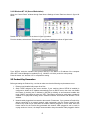
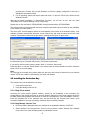
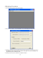
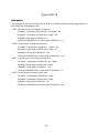
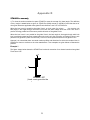
STPRO2PDMSTM User’s Manual MANUALS/STPRO2PDMS™/man1/doc1 Issue October, 2010 STPRO2PDMS STAAD.Pro-to-PDMS User’s Manual Server Version 2.xx 1 STPRO2PDMS User’s Manual Please read the following carefully InfoPlant has a policy of continuing product development; therefore the information contained in this document may be subject to change without notice. This software and this manual have been developed and checked for correctness and accuracy by InfoPlant Technologies Pvt. Ltd. However, no warranty, expressed or implied, is made by InfoPlant Technologies Pvt. Ltd. as to the accuracy or functioning of the software. STAAD.Pro-to-PDMS User’s Manual Server Version 2.60 © October 2010, InfoPlant Technologies Pvt. Ltd. & SST India Pvt. Ltd. All rights reserved. No part of this document may be reproduced, stored in retrieval system or transmitted, in any form or by any means, electronic, mechanical, photocopying, recording or otherwise, without prior written permission of InfoPlant Technologies Pvt. Ltd. & SST India Pvt. Ltd. The software programs described in this document are confidential information and proprietary products of InfoPlant Technologies Pvt. Ltd. or its licensors. STAAD.Pro-to-PDMS and STPRO2PDMS are trademarks of InfoPlant Technologies Pvt. Ltd. & SST India Pvt. Ltd. STAAD.Pro is a trademark of Research Engineers, Corp, USA. Please direct inquiries to 7, Cresant Road Bangalore – 560 001, India. Tel: +91-80-40336999 Fax: +91-80-41494967 Email: [email protected] Email: [email protected] www.infoplantindia.com www.sstindia.net 2 Table of Contents 1. Introduction.......................................................................................................................................... 4 How the Interface works? ................................................................................................................................... 4 2. Installing the Program ....................................................................................................... 5 2.1. Operating System Requirement............................................................................................................... 5 2.2 Installing SST License Manager ............................................................................................................... 5 2.3 Manually Registering Service .................................................................................................................... 5 2.4 Installing the client program STAAD.Pro-to-PDMS Interface .......................................................... 6 2.5 Product Key Generation .............................................................................................................................. 8 2.6 Installing the Activation Key........................................................................................................................ 9 2.7 Renewing/Re-Installing/Repair the License ........................................................................................ 10 3.Loading Catalogues and specification.................................................................................... 11 4. Limitations.......................................................................................................................................... 12 5.Working Procedure .......................................................................................................................... 13 6.Reference ............................................................................................................................................. 15 6.1 COMMENTS.................................................................................................................................................. 15 6.2 GLOBAL DIRECTION ................................................................................................................................ 15 6.3 UNIT ................................................................................................................................................................. 16 6.4 JOINT COORDINATES ............................................................................................................................. 16 6.5 MEMBER INCIDENCES............................................................................................................................ 16 6.6 ELEMENT INCIDENCES SHELL ........................................................................................................... 16 6.7 ELEMENT PROPERTY SPECIFICATION .......................................................................................... 16 6.8 MEMBER PROPERTY............................................................................................................................... 16 6.9 MEMBER TRUSS........................................................................................................................................ 25 6.10 MEMBER RELEASE ................................................................................................................................ 25 6.11 CONSTANTS.............................................................................................................................................. 26 6.12 SUPPORTS................................................................................................................................................. 26 Appendix A.............................................................................................................................................. 27 STAAD.Pro-to-PDMS Section Mapping....................................................................................................... 27 Appendix B.............................................................................................................................................. 29 Orientation ............................................................................................................................................................. 29 Appendix C.............................................................................................................................................. 30 Error messages.................................................................................................................................................... 30 Appendix D.............................................................................................................................................. 31 STAAD.Pro anomaly .......................................................................................................................................... 31 Appendix E.............................................................................................................................................. 35 Technical reference ............................................................................................................................................ 35 3 1. Introduction STAAD.Pro-to-PDMS: STAAD.Pro-to-PDMS Interface (STPRO2PDMS) program is a stand-alone program, which shall be used for transferring section geometry, their properties, support condition etc from STAAD.Pro to PDMS Software The sequence of this interface operation is shown diagrammatically in Figure 1-1. STAAD.Pro STAAD.Pro Input File STPRO2PDMS Mapping DB Macro File PDMS Software Figure 1-1 This manual describes the development done on STAAD.Pro-to-PDMS Interface by InfoPlant Technologies Pvt. Ltd. It is assumed that the user is already familiar with the principles of PDMS Software Structural Application and the practices followed in PDMS Structural catalogue and specifications. It is also assumed that the user has used PDMS Software to generate structures by using available facilities in PDMS Software and the user is familiar with STAAD.Pro. At this stage it is essential to know that PDMS Software and STAAD.Pro use different world coordinate systems; so, it is recommended that the user check the PDMS model once the STAAD.Pro-to-PDMS Interface has generated it. How the Interface works? 1.1 The sections modeled in STAAD.Pro leads to the generation of the STAAD.Pro input command file or the data can be entered manually through the STAAD EDITOR. 1.2 The windows executable STPRO2PDMS.exe reads this STAAD.Pro input file and maps it against Section mapping DB to identify the valid PDMS Software section name that corresponds to the STAAD.Pro section Specification. This executable finally generates macro file (*.mac), by running this file in PDMS Software, the corresponding model can be viewed. 4 2. Installing the Program Before installing the SST License Manager and the Client product on any of your computer, please make sure the computer meets the following requirement listed below. Note: If you are using the old version of SST License Manager (i.e., earlier than version 5.0), then follow the procedure listed in Appendix A of “Security.pdf” to uninstall the same before installing the new version of SST License Manager. 2.1. Operating System Requirement a. Internet Explorer 5.01 or later and Windows Installer 2.0 or later. b. Windows NT 4.0 (Workstation or Server) with Service Pack 6a c. Windows 2000 (Professional, Server, or Advanced Server) d. Windows XP (Personal and Professional) e. Windows Vista (Personal and Professional) 2.2 Installing SST License Manager Locate/Decide the computer that you want to use as a server for the STAAD.Pro-to-PDMS Interface. Any machine available in the network can be used as a server machine and it is not necessary to be a real server. Insert the compact disc supplied by InfoPlant to the CD-ROM drive of the computer, that you decided to use as a server for STAAD.Pro-to-PDMS interface. Wait for few seconds to enable the “Auto play” of the CD. Please note, if the CD-ROM does not start automatically, simply browse the CD, and double-click on the “setup” application icon. You will see a typical window; similar to that shown in the figure left below. Click on “Install SST License Manager” option. You will be shown window similar to that shown in the figure right below. Follow the instructions as they appear on the screen. 2.3 Manually Registering Service The SST License Manager setup program will register and start the service automatically, when you perform step 2.2. If the setup program fails to register the service automatically, then register the service manually as stated below. 5 After the successful installation of the SST License Manager, launch the program “Register.exe” by selecting Start Menu->Programs->SST License Manger->Register SST License Manager from the computer where the SST License Manager is installed. The details are shown graphically below. Select the option “Register SST License Manager” through “Tools->Register SST License Manager” to register the window service as shown in figure left below. After successful registration of the service you will see a message shown in figure right below. 2.4 Installing the client program STAAD.Pro-to-PDMS Interface Locate/Decide the computers that you want to use as clients. The client program STAAD.Pro-to-PDMS Interface can be installed in as many systems as you want. To install STAAD.Pro-to-PDMS Interface on the client computers, insert the compact disc supplied by InfoPlant to the CD-ROM drive and wait for few seconds to enable the Auto play feature. Please note, if the CD-ROM does not start automatically, simply browse the CD, and double-click on the “setup” application icon. You will see a window as shown in figure left of section 1, “Installing the SST License Manager”. Click on “Install STAAD.Pro-to-PDMS” option and follow the instructions as they appear on the screen. For sharing the license information, client computer need to communicate with the server (computer where the SST License Manger is installed). The communication between the client computer and the server computer can be established by setting the Environmental Variable “SSTLM” on the client computers. Please note, the automated procedure for locating the server computer by the client computer for sharing license information is purposefully not given to avoid unnecessary clashes. However, the Environmental variable is set automatically for the machine where SSTLM is installed. In other words, if you install the client program in the same machine where the SST License Manager is installed, then there is no need to set the environmental variable “SSTLM”. If the client program is installed other than the machine where SST License Manager is installed, then follow the procedure listed below for setting the environmental variable under different operating systems. 1. SST License Manager is used as a security system for all InfoPlant products and hence user can have different servers in the same network environment for different InfoPlant products. 2. Can have one server for various InfoPlant products installed in different client machines. 3. Can install both server/client in one computer. 6 4. Can have two different servers for one InfoPlant product by splitting the number of users (not applicable for single user) and 5. Locating the server automatically under a huge network environment is a time consuming process. The procedure for setting the Environmental Variable “SSTLM” in the client machine under different operating systems is listed below. 2.4.1 Windows 2000 (Server/Professional Edition) /Windows XP (Personal and Professional) Open the “Control Panel” window through Start Menu->Settings->Control Panel. Double-click on “SYSTEM” icon as shown in figure left below. Select the tab “Advanced” and press the button “Environmental Variables” as shown in figure right above. Click the button “New” under the “User Variables” as shown in figure below. Type “SSTLM” under the variable name prompt and key in the name or IP Address of the computer where SST License Manager is installed (for e.g., info025 or 192.0.0.4) under the value prompt. Press the button “ok” to complete the setting. 7 2.4.2 Windows NT 4.0 (Server/Workstation) Open the “Control Panel” window through Start Menu->Settings->Control Panel as shown in figure left below. Double-click on “SYSTEM” icon as shown in figure right above. From the window, select the tab “Environment”, you will see a window as shown in figure below. Type “SSTLM” under the variable name prompt and key in the Name or IP Address of the computer where SST License Manager is installed (for e.g., info025 or 192.0.0.4) under the value prompt. Press the button “set” and then “Ok” to complete the setting. 2.5 Product Key Generation Before generating the Product Key, user has to make sure that the following requirements are met. 1. Ethernet card installed with proper driver files. 2. Static TCP/IP assigned to the server machine. If your machine (where SSTLM is installed) is configured to obtain the IP Address automatically from an DHCP server, then user can disable the feature of checking the IP Address by SSTLM by defining an environmental variable with name “SKIPIP” and setting its value as “YES”. This feature can also be used when a product is installed in a Laptop that is being used in a different network environment with different TCP/IP address. 3. Network cable plugged and connected to the network. Please note, if you generate a Product Key without connecting to a network (network cable unplugged), then the license issued for that Product Key could not be used when the network cable is plugged-in. On the other hand, the license issued for the Product Key generated with network cable plugged-in can be used in unplug mode too. Hence, it is always recommended to keep the network cable plugged-in before 8 generating the Product Key on both Desktops as well as Laptops (configured to use both in standalone and network mode). 4. For XP operating system with service pack later than 1.0, open the TCP/IP port 12000 from the Windows Firewall. After the successful installation of Server/Client Programs, you will see an icon with the name “ST2PDMS” in the windows desktop of client computer(s). Double-click on icon and select “STPRO2PDMS” through Interface Menu->STPRO2PDMS. The client program communicates with the server computer and sends request to check for the availability of the license to use the product. The server (SST License Manger) checks for the availability of the license in the windows registry. If not available, program automatically generates a new Product Key and send the same back to the client machine. Client machine then pops up the same in a dialog box as shown in figure below. Enter the details as shown in the figure above and press the button “Get Activation Key”. This will get you the Activation Key for Evaluation the product / Full license for paid users. If you wish to send an email, press the button “More >>” and then “Send email”. Press the “More >> and then “Show Details” if you wish to store the license details in a text file. Press the button “Close” to close the dialog. Note: For receiving the Activation Key, please make sure that you have access to internet from your machine and the TCP/IP port 12000 is not blocked by your hard / soft firewall. 2.6 Installing the Activation Key The Activation Key can be installed in two ways. 1. Using client module and 2. Using the Manage License Tool. 2.6.1 Using Client module Launching the client product (product module), checks for the availability of the Activation Key corresponding to the module and pops up “Security System” dialog box (in the client machine where the InfoPlant product being loaded) with provision to enter the “Activation Key” upon unavailability of the key. Enter the Activation Key in the “Activation Key” text box and click the “Activate Now” button. Upon successful installation, user gets a message “Activation Key successfully installed”. 2.6.2 Using Manage License Tool a. Run the program “ManageLicense.exe” available in the installation directory of “SSTLM”. b. Select “Analyse Tool” from the menu “Tools” for server version or select “Analyse Tool” available in the main menu of the InfoPlant product for standalone version. 9 c. From the dialog box as shown in figure below, select the product from the “Select Product” combo box. d. Select the check box “Install or Repair Activation Key”. This enables the text box below the check box. e. Paste the “Activation Key” in it and press the button “Install Key”. On successful installation, user gets a message “Activation Key successfully installed”. 2.7 Renewing/Re-Installing/Repair the License Follow the steps a. through e. listed in 2.6.2 above to renew/re-install the license (Activation Key). Refer SST License Manager User’s manual for more details. Or Launch the client module and select the option Help->Renew / Repair Activation Key. Paste the Activation Key and press “Activate Now”. 10 3.Loading Catalogues and specification In PDMS, the instances of the section (profiles) geometry in design are generated through catalogue reference. In other words, the section profiles are created/defined as a catalogue component in PDMS Paragon module before the same being used in PDMS Design Module. Hence it is necessary for the user to make sure that the Catalogues for various Standards that are available in STAAD.Pro software is also available in PDMS. If the catalogues corresponding to STAAD.Pro are available in PDMS, then the names of that catalogue component should be mapped with STAAD.Pro catalogue through a Mapping DB supplied along with the Interface. On the other hand, if the catalogues corresponding to STAAD.Pro are not available in PDMS, then the user has to create the same in PDMS Paragon and Map using the Mapping DB supplied along with the interface. The catalogues and the Specification in PDMS format corresponding to those that are available in STAAD.Pro standard tables are supplied with the current version of the interface. The Mapping DB corresponding to the above said is also supplied along with the interface. User can load these catalogues and specifications into PDMS paragon following the procedure given below, if they are not available in PDMS. 1. Launch PDMS and login to paragon module with username and password, which has read/write access. 2. Load the file “AmericanCata.dat” and “AmericanSpwl.dat available in “STPRO2PDMS_Installed_dir\Catalogues\AISC” through the command line of PDMS Paragon Module. Similarly, load all the files available under the folder BRITISH, EUROPEAN and USER. Assuming the STPRO2PDMS application path as “E:\stpro2pdms”, type $m /E:\ st2pdms\catalogues\ AmericanCata.dat Similarly run all the files, as mentioned above. 3. Save the work by typing “Savework” in command line. 4. For testing the interface, few sample models are supplied along with the product. These models are available in “STPRO2PDMS_Installed_dir\samples”. Note: Refer Appendix A on creating and mapping the Catalogues and Specifications in PDMS for the User Defined STAAD.Pro Sections. 11 4. Limitations The present version of the Interface has the following limitations. 1) The General sections are not transferred from STAAD.Pro to PDMS. The general sections are one; they don’t have the geometrical shape. But they are defined with the properties like AX, AY, AZ, Ix, Iy, Iz, YD, ZD, YB, and ZB. These properties are explained below, AX = Cross sectional area of the member. AY = Effective shear area in local y-axis. AZ = Effective shear area in local z-axis. IX = Torsional constant. IY = Moment of inertia about local y-axis. IZ = Moment of inertia about local z-axis (usually major). If any of the above 6 parameters are omitted, it will be calculated from the YD, ZD, YB, and/or ZB dimensions. YD = Depth of the member in local y direction. (Diameter of section for circular members) ZD = Depth of the member in local z direction. If ZD is not provided and YD is provided, the section will be assumed to be circular. YB = Depth of stem for T-section. ZB = Width of stem for T-section or bottom width for TRAPEZOIDAL section. Except the Geometry, all other information’s are transferred to the sections. 2) The composite sections are not transferred from the STAAD.Pro to PDMS. The 'CM' (composite) parameter can be assigned to I-shaped sections only. A 'CM' (composite) section is one obtained by considering a portion of a concrete slab to act in unison with the I- shaped steel section. For more information about Composite Section, refer the STAAD.Pro Technical Reference Manual, 5.20.1 Type Specs and Additional Specs for assigning properties from Steel Table. 12 5.Working Procedure 5.1 On launching the program the below form will appear. 5.2 From the menu “Interface”, click “STPRO2PDMS”. A form will be displayed as shown below. 5.3 Selection of STAAD.Pro Input Command File can be done in two ways viz. by entering the name of the STAAD.Pro Input Command File along with the valid path in the text box provided or by navigating through the corresponding button. 5.4 Similarly, enter the name of the Macro file as explained in Step 5.3 13 5.5 User can transfer the Model under the hierarchy of framework or sub framework. By Default, the name of the framework or sub framework will be displayed in the form or the user can enter the name of the Framework or sub framework manually. 5.6 Click the button “Transfer” to transfer model to Macro file format. Upon successful transfer, user gets the message box as shown below. 5.7 The progress bar shows the progress or completion status of the transformation. After the successful transformation, run the macro file with proper path name in PDMS Design module. So that the corresponding model will appear in the PDMS Design module. For e.g. $m D:\staadpro\sample_model11\structure1.mac Note: When transferring the models from STAAD.Pro to PDMS, check the hierarchy. If the model is transferred under the hierarchy of FRAMEWORK, then create the hierarchy as mentioned below WORLD -> SITE -> ZONE -> STRU If the model is transferred under the hierarchy of sub framework, then create the hierarchy as mentioned below WORLD -> SITE -> ZONE -> STRU -> FRMW 14 6.Reference This section describes in details, the methodology used for transferring the information’s of sections from STAAD.Pro to PDMS. 6.1 COMMENTS STAAD SPACE START JOB INFORMATION ENGINEER DATE 20-Nov-06 END JOB INFORMATION INPUT WIDTH 79 The STAAD SPACE command initiates the STAAD run, allows the user to specify the type of the structure and an optional title. Any STAAD input command file has to start with the word STAAD. START JOB INFORMATION ENGINEER DATE 20-Nov-06 END JOB INFORMATION The above lines indicate the date at which the input command file (job) is created. The INPUT WIDTH commands may be used to specify the width(s) of the lines of input/output file(s). The user may specify the required input/output width, as required, using this command. For INPUT width, 79 are always used. Since above information’s doesn’t contain any valid data, this information’s are not transferred from STAAD.Pro to PDMS 6.2 GLOBAL DIRECTION In STAAD.Pro, two Global directions are there, SET Z UP SET Y UP By default, the Y-axis is the vertical axis. However, the SET Z UP commands may be used to model situations where Z-axis represents the vertical axis (direction of gravity load) of the structure. This situation may arise if the input geometry is created through some CAD software. But in PDMS always SET Z UP. This interface identifies, whether the Global direction is set, SET Z UP or SET Y UP. If SET Z UP then the following condition is used. X=X Y=Y Z=Z And the models are transferred without interchanging the Joint co-ordinate of the each section. If SET Y UP then the following condition is used. X =X Y = -Z 15 Z =Y And the Joint co-ordinate of the each section is interchanged. And the model is transferred accordingly to the PDMS. 6.3 UNIT This command allows the user to specify or change length and force units for input and output. The UNIT command can be specified any number of times in the STAAD.Pro input command file. In STAAD.PRO the units used are "MMS", "CM", "DME", "METER", "KM", "INCH", and "FEET”. This interface converts the "CM", "DME", "METER", "KM", "INCH", or "FEET” into the “MMS” (Millimeter). Since in PDMS millimeter is recommended. 6.4 JOINT COORDINATES These commands allow the user to specify and generate the coordinates of the Joints of the structure. The JOINT COORDINATES command initiates the specification of the coordinates. The joint coordinates command specifies the Cartesian co-ordinate system. Joints are defined using the global X, Y and Z co-ordinates. The JOINT COORDINATES of the STAAD.Pro are transferred as ‘primary nodes’ (PNOD) in PDMS. 6.5 MEMBER INCIDENCES MEMBER INCIDENCES is used to specify Members by defining connectivity between JOINTS (primary nodes) .The position start of the section in PDMS is equal to the node number (1st) of STAAD.Pro member incidence. The position end of the section in PDMS is equal to the node number (2nd) of STAAD.Pro member incidence. 6.6 ELEMENT INCIDENCES SHELL ELEMENT INCIDENCES SHELL is used to specify Shell Elements by defining the connectivity between Joints (primary nodes). Each Shell element incidence must be defined such that the model developed represents one shell structure only, and not two or more separate shells. Element incidence shell must be provided immediately after MEMBER INCIDENCES (if any) are specified. If MEMBER INCIDENCE is provided, Elements number must not coincide with any MEMBER number. The Clockwise or counterclockwise joint numbers represents element connectivity. The Shell or Plate elements are transferred as Panel (PANE) elements in PDMS. The Joints of the element shall be transferred as Panel Vertex Element (PAVE). For more Details about Panels and plates refer the Technical reference manual Structural Design Using PDMS. 6.7 ELEMENT PROPERTY SPECIFICATION ELEMENT PROPERTY SPECIFICATION is used to specify the properties of plate finite elements. Elements of uniform or linearly varying thickness may be modeled using this command. The plate thickness is assigned to the Height attribute of the Panel Loop Element (PLOO) in PDMS. 6.8 MEMBER PROPERTY DEFINE MATERIAL START ISOTROPIC STEEL 16 E 2.05e+008 POIS0SON 0.3 DENSITY 76.8195 ALPHA 1.2e-005 DAMP 0.03 END DEFINE MATERIAL The above lines indicate the material properties of the section and these lines are omitted, when transferring the information’s from STAAD.Pro to PDMS, because the Material Properties can be obtained from the specification reference of the sections. This command initiates the specification of member property. Following are the various options available: 1. Specification from built in steel tables 2. Specification from USER PROVIDED TABLES 3. Specification by assigning profiles 4. Specification of PRISMATIC properties 5. Specification of TAPERED members 1. Specification from built in steel tables The following commands are used for specifying section properties from built-in steel table(s). a. b. c. d. e. f. g. ST specifies single section from the standard built-in tables. RA specifies single angle with reverse Y-Z axes D specifies double channel. LD specifies long leg, back to back, double angle. SD specifies short leg, back to back, double angle. T specifies tee section cut from I shaped beams. TC specifies beams with top cover plate. h. BC specifies beams with bottom cover plate. i. TB specifies beams with top and bottom cover plates. a. ST (single section from the standard built-in tables) ST stands for single section from the standard built-in table. The following are the different types of Single Section. a) Angle b) Channel c) I-Section Consider the example listed below for better understanding. MEMBER PROPERTY AMERICAN 1 TABLE ST W6X25 In the above example, the word “AMERICAN” represents the AMERICAN standard, 1 represents the “Member Index”, ST represent “Single Section” and W6X25 represent the “Staad.Pro Section Name” The interface check whether the member belongs to AMERICAN, BRITISH, or EUROPE etc standard, in the above example the member belongs to the AMERIACN standard, then it goes to AMERIACN standard table and Search for the PDMS section name. Since, we know the STAAD.Pro section name (W6X25), the corresponding PDMS section name and also Section Type can be obtained from the mapping database (AMERICAN STANDARD TABLE). Since PDMS section name is known, the 17 corresponding geometry is obtained by assigning the PDMS section name to the SPREF (specification reference) attribute of the member, whose section start and end is known by the Joint Coordinates. By the section type, user can get the section belongs to Angle, Channel or I-section and the corresponding beta angle is calculated. For more information about calculating the beta angle refer the APPPENDIX B. b. RA (specifies single angle with reverse Y-Z axes) RA stands for the ‘single angle with reverse Y-Z axes’. For more details about the RA, refer the STAAD.Pro Technical Reference 5.20.1, Type Specs and Additional Specs for assigning the properties from the Steel Table. A typical example for RA section is shown below. MEMBER PROPERTY AMERICAN 1 TABLE RA L804012 In the above example, AMERICAN -> AMERICAN standard 1 -> Member index RA -> single angle with reverse Y-Z axes L804012 -> STAAD.Pro Section name For RA, the procedure is same as explained above for ST (‘single section from the standard built-in table). c. D (specifies double channel) The procedure used for creating the double channel is explained below. 1) Create section that specification reference equal to the standard section from the mapping database and create another section of same specification reference and place it at a distance specified in the input command file as SP (SPACE BETWEEN CHANNEL) exactly opposite to each other. 2) The P-Lines are used to calculate the distance between the channels and placing the channels opposite to each other. The P-lines are used for calculating the Distance between the Channels is NA IOC FOC The Channel with their P-lines is shown below. 18 A typical example for the Double channel is shown below. MEMBER PROPERTY AMERICAN 1 TABLE D C3X4 SP 0.25 D stands for Double channel C3X4 is the STAAD.Pro Section name. SP is the Space between the Channels. d. LD (specifies long leg, back to back, double angle) The procedure used for creating the long leg back-to-back double angle is, 1) Create section that specification reference equal to standard section from the mapping database and create another section of same specification reference and place it at a distance specified in the input command file as SP (SPACE BETWEEN ANGLE). 2) The P-Lines are used to place the angle opposite to each other and to calculate the distance between the angles. The P-lines are used in placing the angles opposite of each other is, 1) NA 2) NAL 3) NAR The angle with their P-lines is shown below. 19 A typical example for the long leg back-to-back double angle is shown below. MEMBER PROPERTY AMERICAN 1 TABLE LD L20202 SP 0.25 D stands for long leg back-to-back double angle L20202 is the STAAD.Pro Section name. SP is Space between the angles. 20 e. SD (specifies short leg, back to back, double angle) The procedure used for creating the short leg back-to-back double angle is, 1) Create section that specification reference equal to standard section from the mapping database and create another section of same specification reference and place it at a distance specified in the input command file as SP (SPACE BETWEEN ANGLE). 2) The P-Lines are used to calculate the distance between the angle and also placing the angle opposite to each other. The P-lines are used for placing the short leg back-to-back double angle opposite to each other is, 1) NA 2) NAB 3) NAT The angle with their P-lines is shown below. MEMBER PROPERTY AMERICAN 1 TABLE SD L20202 SP 0.25 D stands for short leg back-to-back double angle L20202 is the STAAD.Pro Section name. SP is Space between the angles. 21 f. T (specifies tee section cut from I shaped beams) The 'T' parameter stands for a T-shaped section obtained by cutting an I-shaped section at exactly its mid height level along the web. Hence, the area of a T shape is exactly half the area of the corresponding I shape. The depth of a T shape is half the depth of the I shape it was cut from. If this interface identifies the member as ‘T’ section, since the interface knows the STAAD.Pro section name, it gets the corresponding PDMS section name from mapping database and assign it to the SPREF (specification reference) attribute of the section to get the corresponding geometry. A typical example for the T section is, MEMBER PROPERTY AMERICAN 1 TABLE T M6X20 T specifies tee section cut from I shaped beams M6X20 is the STAAD.Pro Section name. g. TC (specifies beams with top cover plate) The procedure used for creating the top cover plate is, 1) Create section whose specification reference is equal to the standard section from the mapping database and create box from the plate information provided in the input command file and place it above the I-section. 2) For placing the box above the I-section, the following p-lines are used. a) NA b) TOS c) RTOS By using these p-lines, calculating the direction of the boxes and placing it exactly above the I-section. A typical example for the beams with top cover plate is, MEMBER PROPERTY AMERICAN 1 TABLE TC M6X20 WP 250 TH 50 TC specifies beams with top cover plate M6X20 is the STAAD.Pro Section name. WP is the width of the plate. TH is the thickness of the plate. The I-section with P-lines is shown in the figure 6.6. h. BC (specifies beams with bottom cover plate) The procedure used for creating the bottom cover plate is, 1) Create section whose specification reference is equal to the standard section from the mapping database and create box from plate information provided in the input command file and place it below the I-section. 2) For placing the box below the I-section, the following p-lines are used. a) NA b) BOS c) RBOS 22 By using these p-lines, calculating the direction of the boxes and placing it exactly below the I-section. A typical example for the beams with bottom cover plate is, MEMBER PROPERTY AMERICAN 1 TABLE BC M6X20 WP 250 TH 50 BC specifies beams with bottom cover plate M6X20 is the STAAD.Pro Section name. WP is the width of the plate. TH is the thickness of the plate. The I-section with P-lines is shown in the figure 6.6. I. TB (specifies beams with top and bottom cover plates) The procedure used for creating the top and bottom cover plate is, 1) Create section whose specification reference is equal to the standard section from the mapping database and create box from plate information provided in the input command file and place it above and below the I-section. 2) For placing the box above and below the I-section, the following p-lines are used. 1) NA 2) TOS 3) BOS 4) RBOS 5) RTOS By using these p-lines, calculating the direction of the boxes and placing it exactly above and below the Isection. A typical example for the beams with top and bottom cover plate is MEMBER PROPERTY AMERICAN 1 TABLE TB M6X20 WP 250 TH 50 TB specifies beams with top and bottom cover plates M6X20 is the STAAD.Pro Section name. WP is the width of the plate. TH is the thickness of the plate. The I-section with their P-lines is shown below. 23 FIGURE 6.6 I-SCTN WITH P-LINES 2. Specification from USER PROVIDED TABLES If the interface identifies the UPTABLE in the MEMBER PROPERTY in input command file, it collects the section specification and maps it against the mapping database and get the corresponding PDMS section name. Since the PDMS section name is known, the corresponding geometry is obtained by assigning the PDMS section name to the SPREF (specification reference) of the section, that section start and end is known by the Joint Coordinates. For more details about the USER PROVIDED TABLE refer the Technical Reference 5.20.4 Property Specification from User Provided Table 3 Specification by assigning profiles The ASSIGN command may be used to instruct the program to assign a suitable steel section to a frame member based on the profile-specification shown below. BEAM COLUMN CHANNEL ANGLE DOUBLE-ANGLE This section doesn’t exist in PDMS. Hence, these sections are created in paragon and mapped it against the mapping database. If the interface identifies the ASSIGN in the MEMBER PROPERTY in the input command file, it collects the profile-specification and maps it against the mapping database and get the corresponding PDMS section name. Since PDMS section name is known, the corresponding geometry is obtained by assigning the PDMS section name to the SPREF (specification reference) of the section, that section start and end is known by the Joint Coordinates. For more details about creating the sections refer the PDMS STRUCTURAL DEIGN USING PDMS VERSION 11.2. 24 4 Specification of PRISMATIC properties The prismatic properties are the non-standard sections. In prismatic properties there are different types a) Circle b) Rectangle c) Tee d) Trapezoidal e) Tapered Tube d) General In Tapered tube there are different types Round HexDecagonal DoDecagonal Octagonal Hexagonal Square The circle, rectangle, trapezoidal, Tapered Tube etc section doesn’t exist in PDMS. Hence these sections are created in paragon and mapped against the mapping database. If the interface identifies the section as circle, rectangle, Tee, Tapered Tube or Trapezoidal, it gets the corresponding PDMS section name from the mapping database and assigned it to the section and the corresponding values are passed as a Design Parameter to the section. Corresponding to the Design Parameter values, geometry will be assigned. As mentioned in limitations, General sections are not transferred. The corresponding message you can get it in LOG file. For more details about the Tapered Tube sections, refer the STAAD.Pro Technical reference manual, 5.20.2.1 Prismatic Tapered Tube Property Specification. 5 Specification of TAPERED members The TAPERED member is a non-standard I- section. If the interface identifies the TAPERED in the MEMBER PROPERTY in the input command file, it collects the section specification and maps it against the mapping database and gets the corresponding PDMS section name from the mapping database and assigned it to the section and the corresponding values are passed as a Design Parameter to the section. Corresponding to the Design Parameter values, geometry will be assigned. 6.9 MEMBER TRUSS When transferring the information from STAAD.Pro to PDMS, if truss member exist, that values are assigned to the ‘FUNCTION’ attributes of the section element (SCTN). 6.10 MEMBER RELEASE When transferring the data from STAAD.Pro to PDMS, if member release exists, that values are assigned to the ‘SRELEASE’ or ‘ERELEASE’ attributes of the section Element (SCTN). 25 6.11 CONSTANTS The constant keyword is used for assigning the beta angle to the section. The orientation is taken care through the BETA angle. For more details about orientation refer APPENDIX B 6.12 SUPPORTS When transferring the data from STAAD.Pro to PDMS, if member support exists, that values are assigned to the ‘FIXITY attribute of PNOD’. Syntax for filling FIXITY attribute of PNOD is a. FIXED b. PINNED c. FIXED BUT <Release-Spec> [Spring-SPEC] Release-Spec FX, FY, FZ, MX, MY & MZ Spring-Spec KFX <f1>, KFY <f2>, KFZ <f3>, KMX <f4>, KMY <f5> & KMZ <f6> Examples FIXED BUT FX MZ FIXED BUT MZ KFX 50.0 KFY 75. For more details about Fixity and primary node refer the APPENDIX E 26 Appendix A STAAD.Pro-to-PDMS Section Mapping The ST2PDMS interface reads the member properties from the STAAD.Pro input file. The properties read from the STAAD.Pro input file may be Standard or Non standard section. This interface maps it against the mapping database and gets the corresponding PDMS section name. If a member belongs to the Standard sections, the interface gets the specification reference from the standard section-mapping database. If a member belongs to the non-standard section, the interface gets the specification reference from the User defined section-mapping database. The details on mapping sections are described below. For mapping sections from STAAD.Pro to PDMS software two mapping DBs are provided namely StandardSection.mdb and UserdefinedSection.mdb as specified above. StandardSection.mdb contains tables which are named after specific standards e.g. The table named “American” represents the AISC standard, the table named “British” represents British standard so on and so forth. Each table contains five fields viz. “CATREF”, “SPREF”,” STAADNAME”,”SECTIONTYPE” and “TANALPHA”. As the names suggest CATREF contains the name of the section in the Catalogue of PDMS, SPREF contains the specification reference name in PDMS software; STAADNAME is the corresponding name of the section in STAAD.pro.The SECTIONTYPE is used to identify the member type e.g. The member belongs to the type of channel, angle or I-section. While mapping a section from STAAD.Pro to PDMS, the Specification reference is used. TANALPHA is the arctan of the angle (tan ) between the principal Axis system for second moment of area and local y-z axis system of the section. Sample Table in StandardSection.mdb CATREF STAADNAME SECTIONTYPE SPREF TANALPHA S10x25.4 S10X25 I AISC-SPEC/S10x25.4 0 S10x35 S10X35 I AISC-SPEC/S10x35 0 S12x31.8 S12X31 I AISC-SPEC/S12x31.8 0 S12x35 S12X35 I AISC-SPEC/S12x35 0 S12x40.8 S12X40 I AISC-SPEC/S12x40.8 0 User defined mapping database: In user-defined section mapping database each table contains three fields viz. CATREF”, “SPREF” and ”SECTIONTYPE”. As the names suggest CATREF contains the name of the section in the Catalogue of PDMS, SPREF contains the specification reference name PDMS software. As the name suggests SECTIONTYPE is used to identify the member type e.g. the member may belongs to the type of rectangle, circle, Tee etc. Sample Table in Userdefinedsection.mdb SPREF SECTIONTYPE CATREF DESPAR-SEC/Rectagle_with_design_parameters RECTAGLE Rectagle_with_design_parameters DESPAR-SPEC/Circle_with_design_parameters CIRCLE Circle_with_design_parameters DESPAR-SPEC/Tee_with_design_parameters TEE Tee_with_design_parameters 27 SPREF SECTIONTYPE CATREF DESPAR-SPEC/Tube_with_design_parameters TUBE DESPAR-SPEC/Trapez_with_design_parameters TRAPEZOIDAL Trapez_with_design_parameters 28 Tube_with_design_parameters Appendix B Orientation The orientation is taken care through the beta angle of the PDMS, because the beta angle definition in both STAAD.Pro and PDMS are equal. 1. SET Z UP and section is not along the vertical axis ST ANGLE = (beta angle of STAAD.Pro) - 90 + alpha – 180 RA ANGLE = (beta angle of STAAD.Pro) + alpha – 180 CHANNEL = beta angle of STAAD.Pro + 0 I-SCTN and TAPERED SCTN = (beta angle of STAAD.Pro) + 0 2. SET Z UP and section is along the vertical axis ST ANGLE = (beta angle of STAAD.Pro) + alpha – 180 RA ANGLE = (beta angle of STAAD.Pro) + alpha – 90 CHANNEL = beta angle of STAAD.Pro + 90 I-SCTN and TAPERED SCTN = (beta angle of STAAD.Pro) + 90 3. SET Y UP and section is not along the vertical axis ST ANGLE = (beta angle of STAAD.Pro) - 90 + alpha RA ANGLE = (beta angle of STAAD.Pro) + alpha CHANNEL = beta angle of STAAD.Pro + 180 I-SCTN and TAPERED SCTN = (beta angle of STAAD.Pro) + 0 4. SET Y UP and section is along the vertical axis ST ANGLE = (beta angle of STAAD.Pro) + alpha RA ANGLE = (beta angle of STAAD.Pro) + alpha CHANNEL = beta angle of STAAD.Pro – 90 I-SCTN and TAPERED SCTN = (beta angle of STAAD.Pro) + 90 29 Appendix C Error messages "Enter all the necessary data and proceed." Description: Either the textbox for neutral file (*.mac) or STAAD.Pro input file (*.std) or both is not filled. "STAAD.Pro file does not exist." Description: The STAAD.Pro file name filled in the textbox for STAAD.Pro file does not exist. "Mac file path does not exist." Description: The path filled in the textbox for Macro input file is not valid. "Server not found. SSTLM Service is not running in Server or COMPUTER_NAME in SSTLM Environmental variable is wrong." Description: Server for the STAAD.Pro not specified. Refer, security.pdf and Install.hlp files for more details on specifying environmental variable “SSTLM”. LOG FILE: In log file, the following messages may be appear. 1) “The Geometry of the General sections <Sections ID> is not transferred”. This type of messages appears in the log file only when the general sections exist in the MEMBER PROPERTY. 2) “SPREF is not available for section <Section ID>”. This type of messages appear in the log file, when the specification reference of the section is not available in the mapping database due to mismatch of the sections in the mapping database or that section doesn’t exist in the mapping data base. 30 Appendix D STAAD.Pro anomaly 1) To orient the section members in space STAAD.Pro uses the concept of (beta) angle. The definition of the angle is stated below as given in STAAD.Pro (2004) manual. It should be noted that the set of rules given below are applicable when global Z-axis direction is set “UP” in STAAD.Pro. When the local x-axis is parallel to the global Y-axis, as in the case of a column in a structure, the beta angle is the angle through which the local z-axis has been rotated about the local x-axis from a position of being parallel and in the same positive direction of the global Z-axis. When the local x-axis is not parallel to the global Y-axis, the beta angle is the angle through which the local coordinate system has been rotated about the local x-axis from a position of having the local z-axis parallel to the global X-Z plane and the local y-axis in the same positive direction as the global Y-axis. However it is noticed that there are certain section profiles and directions for which the rendered view in STAAD.Pro does not conform to the rules stated above. Two examples are given below to illustrate the problem. Example 1 The figure shown below shows the STAAD.Pros local axis convention for a channel section when global Z-axis is set “UP”. z y Channel – ST (Local x-axis goes into the ) 31 The figure below shows the positioning of the channel section in STAAD.Pro when the local x-axis of the channel section is parallel to the global Z-axis. Z x y X Y z As the local x-axis of the section is not parallel to the global Y-axis the 2nd part of the definition stated in the previous page will hold good. So for = 0 according to the definition the local y-axis should be in the same direction as the global Y-axis direction, but as the figure above suggests the local y-axis is pointing towards the opposite direction of global Y-axis. The STAAD.Pro commands for the input file for the above problem are given below. STAAD.Pro Commands for the input file *************************************************************************************************STAAD SPACE START JOB INFORMATION ENGINEER DATE 07-Jun-06 END JOB INFORMATION INPUT WIDTH 79 SET Z UP 32 UNIT METER KN JOINT COORDINATES 1 0 0.5 0; 2 0 0.5 4; MEMBER INCIDENCES 1 1 2; DEFINE MATERIAL START ISOTROPIC STEEL E 2.05e+008 POISSON 0.3 DENSITY 76.8195 ALPHA 1.2e-005 DAMP 0.03 END DEFINE MATERIAL MEMBER PROPERTY AMERICAN 1 TABLE ST C8X11 CONSTANTS MATERIAL STEEL MEMB 1 FINISH ************************************************************************************************* The example given above is not a singular case where STAAD.Pro graphical view errs. It is found that the error is noticeable for unsymmetrical sections like channel, and angle section. Given below is another example for the user’s interest. Example 2 STAAD.Pro Commands for the input file ************************************************************************************************* STAAD SPACE START JOB INFORMATION ENGINEER DATE 07-Jun-06 END JOB INFORMATION INPUT WIDTH 79 SET Z UP UNIT METER KN JOINT COORDINATES 1 0 0 0.5; 2 4 0 0.5; 33 MEMBER INCIDENCES 1 1 2; DEFINE MATERIAL START ISOTROPIC STEEL E 2.05e+008 POISSON 0.3 DENSITY 76.8195 ALPHA 1.2e-005 DAMP 0.03 END DEFINE MATERIAL MEMBER PROPERTY AMERICAN 1 TABLE ST C8X11 CONSTANTS MATERIAL STEEL MEMB 1 FINISH ******************************************************************************************** 34 Appendix E Technical reference 1) Structural profile section The paragraphs below give an account of the attributes of the section (SCTN) element, which are used in assigning the values, when transferring the data from STAAD.Pro to PDMS. 1.1 Design Parameter (Desparam) This attributes holds the physical dimensions of the section (SCTN) element, which are set in the design module. 1.2 Function To identify members, which can carry only axial load e.g. bracing members, truss members etc. The function attribute can be set as “Bracing member” or “Truss member”. 1.3 Start Release and End Release (SRelease and Erelease) This provides the member release condition at the end node and start node of the section (SCTN) element. 2) Primary node These node define the start node, end node, and intermediate nodes of sections 2.1 Fixity This attribute provides information about external support. 3) Plate/Shell finite element The Plate/Shell finite element is based on the hybrid element formulation. The element can be 3-noded (triangular) or 4-noded (quadrilateral). If all the four nodes of a quadrilateral element do not lie on one plane, it is advisable to model them as triangular elements. The thickness of the element may be different from one node to another. "Surface structures" such as walls, slabs, plates and shells may be modeled using finite elements. 35